US6629216B1 - Fibre channel by-pass - Google Patents
Fibre channel by-passDownload PDFInfo
- Publication number
- US6629216B1 US6629216B1US09/343,344US34334499AUS6629216B1US 6629216 B1US6629216 B1US 6629216B1US 34334499 AUS34334499 AUS 34334499AUS 6629216 B1US6629216 B1US 6629216B1
- Authority
- US
- United States
- Prior art keywords
- port
- selector
- coupled
- output
- disk drives
- Prior art date
- Legal status (The legal status is an assumption and is not a legal conclusion. Google has not performed a legal analysis and makes no representation as to the accuracy of the status listed.)
- Expired - Lifetime
Links
Images


Classifications
- G—PHYSICS
- G06—COMPUTING OR CALCULATING; COUNTING
- G06F—ELECTRIC DIGITAL DATA PROCESSING
- G06F11/00—Error detection; Error correction; Monitoring
- G06F11/07—Responding to the occurrence of a fault, e.g. fault tolerance
- G06F11/16—Error detection or correction of the data by redundancy in hardware
- G06F11/20—Error detection or correction of the data by redundancy in hardware using active fault-masking, e.g. by switching out faulty elements or by switching in spare elements
- G06F11/2053—Error detection or correction of the data by redundancy in hardware using active fault-masking, e.g. by switching out faulty elements or by switching in spare elements where persistent mass storage functionality or persistent mass storage control functionality is redundant
- G06F11/2094—Redundant storage or storage space
- G—PHYSICS
- G06—COMPUTING OR CALCULATING; COUNTING
- G06F—ELECTRIC DIGITAL DATA PROCESSING
- G06F11/00—Error detection; Error correction; Monitoring
- G06F11/07—Responding to the occurrence of a fault, e.g. fault tolerance
- G06F11/16—Error detection or correction of the data by redundancy in hardware
- G06F11/20—Error detection or correction of the data by redundancy in hardware using active fault-masking, e.g. by switching out faulty elements or by switching in spare elements
- G06F11/2002—Error detection or correction of the data by redundancy in hardware using active fault-masking, e.g. by switching out faulty elements or by switching in spare elements where interconnections or communication control functionality are redundant
- G06F11/2005—Error detection or correction of the data by redundancy in hardware using active fault-masking, e.g. by switching out faulty elements or by switching in spare elements where interconnections or communication control functionality are redundant using redundant communication controllers
- G—PHYSICS
- G06—COMPUTING OR CALCULATING; COUNTING
- G06F—ELECTRIC DIGITAL DATA PROCESSING
- G06F11/00—Error detection; Error correction; Monitoring
- G06F11/07—Responding to the occurrence of a fault, e.g. fault tolerance
- G06F11/16—Error detection or correction of the data by redundancy in hardware
- G06F11/20—Error detection or correction of the data by redundancy in hardware using active fault-masking, e.g. by switching out faulty elements or by switching in spare elements
- G06F11/2002—Error detection or correction of the data by redundancy in hardware using active fault-masking, e.g. by switching out faulty elements or by switching in spare elements where interconnections or communication control functionality are redundant
- G06F11/2007—Error detection or correction of the data by redundancy in hardware using active fault-masking, e.g. by switching out faulty elements or by switching in spare elements where interconnections or communication control functionality are redundant using redundant communication media
- G06F11/201—Error detection or correction of the data by redundancy in hardware using active fault-masking, e.g. by switching out faulty elements or by switching in spare elements where interconnections or communication control functionality are redundant using redundant communication media between storage system components
- H—ELECTRICITY
- H04—ELECTRIC COMMUNICATION TECHNIQUE
- H04L—TRANSMISSION OF DIGITAL INFORMATION, e.g. TELEGRAPHIC COMMUNICATION
- H04L12/00—Data switching networks
- H04L12/28—Data switching networks characterised by path configuration, e.g. LAN [Local Area Networks] or WAN [Wide Area Networks]
- H04L12/42—Loop networks
- H04L12/437—Ring fault isolation or reconfiguration
Definitions
- This inventionrelates generally to data storage systems and more particularly to data storage systems having a plurality of magnetic storage disk drives in a redundancy arrangement whereby the disk drives are controllable by first disk controllers and second disk controllers. Still more particularly, the invention also relates to systems of such type wherein the disk drives are coupled to the disk controllers through a series, unidirectional, “ring” or, fibre channel protocol, communication system.
- each setis controlled by a first disk controller and a second disk controller. More particularly, in order to enable the set of disk drives to operate in the event that there is a failure of the first disk controller, each set is also coupled to a second, or redundant disk controller. Therefore, if either the first or second disk controller fails, the set can be accessed by the other one of the disk controllers.
- FCfibre channel
- ringa separate, independent, “ring”, or fibre channel communication protocol.
- two fibre channelsare provided for each set of disk drives and their disk interfaces; a first fibre channel and a second fibre channel.
- the first fibre channelwhen using the fibre channel communication protocol, if any element in the channel becomes inoperative, the entire channel becomes inoperative. That is, if the first disk controller becomes inoperative, or if any one of the disk drives in the set coupled to the first channel becomes inoperative (i.e., as where the disk interface fails, the disk interface is inoperative, or removed with its coupled disk drive, or where the disk drive coupled thereto fails, or is removed), the first fibre channel, is “broken”, or open, and becomes inoperative. The data stored in the entire portion of the set of disk drives coupled to the first disk channel is therefore unavailable until the inoperative first disk controller or inoperative disk drive is replaced. This is true with either the first channel or the second channel.
- a switchsometimes referred to as an LRC (i.e., a loop resiliency circuit) switch. Such LRC switch is used to remove an inoperative disk drive from its channel.
- a printed circuit boardis provided for each disk drive.
- the printed circuit boardhas a pair of LRCs, one for the first channel and one for the second channel.
- the open channelmay be “closed” in the event of an inoperative disk drive by placing the LRC thereof in a by-pass condition. While such suggested technique solves the inoperative disk drive, or open channel problem, if one of the pair of LRCs fails, the entire printed circuit board having the pair of LRCs must be replaced thereby disrupting both the first and second channels; and, hence, disrupting the operation of the entire data storage system.
- n LRC switches(where n is the number of disk drives in the set) in the first channel, i.e., one LRC for each one the n disk drives in the set and another n LRC switches in the second channel for each one of the n disk drives in the second channel.
- the first channel set of n LRCsis mounted on one printed circuit board and the second channel set of n LRCs is mounted on a different printed circuit board.
- a backplaneis used to interconnect the two LRC printed circuit boards, the associated multiplexers, and the disk drives.
- an elaborate, complex, fan-out wiring arrangementhas been suggested for the backplane.
- the slots provided for the two LRC boardseliminates two disk drives, and the disk interfaces which would otherwise be plugged into these two slots of the backplane.
- a data storage systemhaving a plurality of disk drives. Each one has a pair of ports.
- a pair of directorsis included for controlling the flow of information (i.e, data) to and from the disk drives.
- a first fibre channel port by-pass selector sectionis provided.
- the first fibre channel selector sectionincludes: an input/output port coupled to a first one of the directors; and, a plurality of output/input ports connected between a first one of the ports of the plurality of disk drives through a first plurality of fibre channel links.
- the first fibre channel port by-pass selector sectionis adapted to couple the first one of the directors serially to one, or ones, of the first ports of the plurality of disk drives through a first fibre channel selectively in accordance with a control signal fed to the first fibre channel by-pass selector.
- the first fibre channelincludes one, or more, of the first plurality of fibre channel links.
- a second fibre channel port by-pass selector sectionis provided having an input/output port coupled to a second one of the directors and a plurality of output/ports serially connected between a second one of the pair of ports of the plurality of disk drives through a second plurality of fibre channel links.
- the second fibre channel port by-pass selector sectionis adapted to couple the second one of the directors serially to one, or ones, of the second ports of the plurality of disk drives through a second fibre channel selectively in accordance with the control signal.
- the second fibre channelincludes one, or more, of the second plurality of fibre channel links.
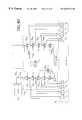
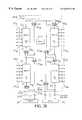
- FIG. 1is a block diagram of a data storage system according to the invention.
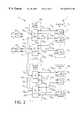
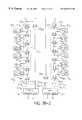
- FIG. 2is a block diagram of a redundant fibre channel network used in the system of FIG. 1 according to the invention
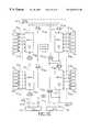
- FIG. 3is a block diagram of a port by-pass section used in the redundant fibre channel network of FIG. 3 coupled to a bank of disk drives used in the system of FIG. 1 according to the invention;
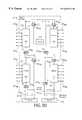
- FIGS. 4, 4 A, 4 B, 4 C and 4 Dare block diagrams of the system of FIG. 1 arranged in an expanded configuration according to the invention
- FIGS. 5, 5 A and 5 Bare block diagrams of a redundant fibre channel network adapted for use in the system of FIG. 1 according to the invention
- FIGS. 5C-5Gare diagrams of the network of FIGS. 5, 5 A and 5 B configured in a number of contracted configurations according to the invention.
- a data storage system 10is shown wherein a host computer 12 is coupled to a bank 14 of disk drives through a system interface 16 .
- the system interface 16includes a cache memory 18 , having high memory address sections 18 H and low address memory sections 18 L.
- a plurality of directors 20 0 - 20 15 .is provided for controlling data transfer between the host computer 12 and the bank 14 of disk drives as such data passes through the cache memory 18 .
- a pair of high address busses TH, BHis electrically connected to the high address memory sections 18 H.
- a pair of low address busses TL, BLelectrically connected to the low address memory sections 18 L.
- the cache memory 18has a plurality of storage location addresses.
- each one of the directors 20 0 - 20 15is electrically connected to one of the pair of high address busses TH, PH and one of the pair of low address busses TL, BL.
- each one of the directors 20 0 - 20 15is able to address all locations in the entire cache memory 18 (i.e., to both the high address memory sections 18 H and the low address memory sections 18 L) and is therefore able to store data in and retrieve data from any storage location in the entire cache memory 18 .
- a rear-end portion of the directorshere directors 20 0 - 20 3 and 20 12 - 20 15 , is electrically connected to the bank 14 of disk drives through fibre channel (FC) port by-pass sections 23 1 - 23 8 (described in more detail in connection with FIG. 3 ), respectively.
- a front-end portion of the directorshere directors 20 4 - 20 11 , is electrically connected to the host computer 12 through I/O adapter cards 22 1 - 22 8 , respectively, as indicated.
- FCfibre channel
- I/O adapter cards 22 1 - 22 8I/O adapter cards 22 1 - 22 8
- the host computer 12issues a write request to one of the front-end directors 20 4 - 20 11 to perform a write command.
- One of the front-end directors 20 4 - 20 11replies to the request and asks the host computer 12 for the data.
- the directordetermines the size of the data and reserves space in the cache memory 18 to store the request.
- the front-end directorthen produces control signals on either a high address memory bus (TH or BH) or a low memory address bus (TL, BL) connected to such front-end director depending on the location in the cache memory 18 allocated to store the data and enable the transfer to the cache memory 18 .
- TH or BHhigh address memory bus
- TL, BLlow memory address bus
- the host computer 12then transfers the data to the front-end director.
- the front-end directorthen advises the host computer 12 that the transfer is complete.
- the front-end directorlooks up in a Table, not shown, stored in the cache memory 18 to determine which one of the rear-end directors 20 0 - 20 3 and 20 12 - 20 15 is to handle this request.
- the Tablemaps the host computer 12 address into an address in the bank 14 of disk drives.
- the front-end directorthen puts a notification in a “mail box” (not shown and stored in the cache memory 18 ) for the rear-end director which is to handle the request, the amount of the data and the disk address for the data.
- Other rear-end directorspoll the cache memory 18 when they are idle to check their “mail boxes”.
- the rear-end directorprocesses the request, addresses the disk drive in the bank, reads the data from the cache memory and writes it into the addresses of a disk drive in the bank 14 .
- the systemoperates in a reciprocal manner.
- Each one of the rear-end portion of the directors 20 0 - 20 3is identical in construction and are described in detail in the above-referenced co-pending patent application Ser. No. 09/224,194 to include a pair of central processing sections, CPU X and CPU Y, a dual port random access memory (RAM), and shared resources (Flash memories, etc,) coupled to the bank 14 of disk drives (FIG. 1) through the fibre channel (FC) port by-pass sections (FIG. 3 ), as indicated and to a high memory address bus, here TH, and low memory address bus, here BL.
- the director 20 0 - 20 3 and 20 12 - 20 15has a first output port, A, and a second output port, B.
- each one of the redundant fibre channel (FC) networks 25 1 - 25 4also includes pairs of the fibre channel (FC) port by-pass sections 23 1 , 23 2 ; 23 3 , 23 4 ; 23 5 (not shown), 23 6 (not shown); and, 23 7 , 23 8 , respectively, as indicated and disk drive sets 14 1 , 14 2 ; 14 3 , 14 4 ; 14 5 (not shown), 14 6 (not shown); and, 14 7 , 14 8 , respectively, as indicated.
- Each one of the pairs of the redundant fibre channel (FC) networks 25 1 - 25 4is identical in construction, an exemplary one thereof, here redundant fibre channel (FC) networks 25 1 is shown in detail in FIG. 2 .
- the first port A and second port B of director 20 0is connected to both FC port by-pass section 23 1 and to FC port by-pass section 23 2 .
- the first port A and second port B of director 20 1is connected to both FC port by-pass section 23 1 and to FC port by-pass section 23 2 .
- both directors 20 0 and 20 1 of the redundant FC network 25 1are connected to the pair of FC port by-pass sections 23 1 , 23 2 .
- Each one of the FC port by-pass sections 23 1 , 23 2includes a pair of FC port by-passes 34 A and 34 B .
- Each one of the FC port by-passes 34 A and 34 Bis connected to a corresponding one of a plurality of sets 14 1 , 14 2 of the disk drives in the bank of disk drives 14 (FIG. 1 ).
- director 20 0is connected to busses TH and BL and that director 20 1 is connected to busses TL and BH.
- the redundant FC network 25 1(FIG. 1) is connected to all four busses TH, BH, TL, and BL.
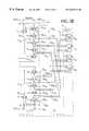
- each one of the disk drive sets 14 1 , 14 2includes a plurality of, here for example eight, disk drives 19 1 - 19 8 , it being understood that the number of disk drives 19 in a set can be selected in accordance with the requisite storage requirements. It is also noted that each one of the disk drives 19 1 - 19 8 includes a pair of input/output ports A, B. As noted above, each one of the FC port by-pass sections 23 1 - 23 8 is identical in construction. An exemplary one thereof, here FC port by-pass section 23 1 is shown in FIG.
- the fibre channel port by-pass selector section 23 1is adapted to couple port A of director 20 , serially to a selected one, or ones, of port A of the plurality of disk drives 19 1 - 19 8 in set 14 1 through a first fibre channel comprising one, or more, of the plurality of fibre channel links 29 A1 - 29 A8 during a normal mode of operation.
- the fibre channel port by-pass selector section 23 1also has an input/output port 30 B coupled to the A port of director 20 , and a plurality of output/ports 32 B1 - 32 B8 serially connected between the B ports of the plurality of disk drives 19 1 - 19 8 through fibre channel links 29 B1 - 29 B8 , as indicated.
- the fibre channel port by-pass selector section 23 1is adapted to couple the A port of director 20 1 serially to a selected one, or ones, of the B ports of the plurality of disk drives 19 1 - 19 8 in set 14 1 through a second fibre channel comprising one, or more, of the second plurality of fibre channel links 29 B1 - 29 B8 in the normal operating mode.
- fibre channel port by-pass selector section 23 2 in FIG. 2is shown to includes: an input/output port 30 A coupled here, however, coupled to the B port of director 20 0 and a plurality of, here in this example, eight, output/input ports 32 A1 - 32 A8 serially connected between port A of the plurality of disk drives 19 1 - 19 8 in set 14 2 through a plurality of fibre channel links 29 A1 - 29 A8 .
- the fibre channel port by-pass selector section 23 2is adapted to couple port B of director 20 0 serially to a selected one, or ones, of port A of the plurality of disk drives 19 1 - 19 8 in set 14 2 through a first fibre channel comprising one, or more, of the plurality of fibre channel links 29 A1 - 29 A8 in section 23 2 during a normal node of operation.
- the fibre channel port by-pass selector section 23 2also has an input/output port 30 B coupled to the B port of director 20 1 and a plurality of output/ports 32 B1 - 32 B8 serially connected between the B ports of the plurality of disk drives 19 1 - 19 8 in set 14 2 through fibre channel links 29 B1 - 29 B8 , as indicated.
- the fibre channel port by-pass selector section 23 2is adapted to couple the B port of director 20 1 serially to a selected one, or ones, of the B ports of the plurality of disk drives 19 1 - 19 8 in set 14 2 through a second fibre channel comprising one, or more, of the second plurality of fibre channel links 29 B1 - 29 B8 in section 23 2 in the normal operating mode.
- director 20 0is able to access the disk drives 19 1 - 19 8 in set 14 2 through its port B in the event of a failure in director 20 1 and, likewise, director 20 1 is able to access disk drives 19 1 - 19 8 in set 14 1 through its A port in the event of a failure in director 20 0 .
- both sets of disk drives 14 1 and 14 2are still accessible from one of the directors 20 0 and 20 1 .
- the set 14 1 of disk drivesis accessible from director 20 1 , via the path between port A of director 20 1 , the port B by-pass 34 B of fibre channel by-pass section 23 1 , and the port B of the disk drives in set 14 1 .
- the set 14 1 of disk drivesis accessible from director 20 1 , via the path between port A of director 20 0 , the port A by-pass 34 A of fibre channel by-pass section 23 1 , and the port A of the disk drives in set 14 1 .
- the set 14 2 of disk drivesis accessible from director 20 0 , via the path between port B of director 20 1 , the port B by-pass 34 B of fibre channel by-pass section 23 1 , and the port B of the disk drives in set 14 2 .
- the set 14 2 of disk drivesis accessible from director 20 0 , via the path between port B of director 20 0 , the port A by-pass 34 A of fibre channel by-pass section 23 2 , and the port A of the disk drives in set 14 2 .
- FC port by-pass section 23 1includes a pair of FC port by-passes 34 A , 34 B .
- the FC port by-pass 34 Ais coupled between input/output port 30 A and the A ports of the disk drives 19 1 - 19 8 in set 14 1 through fibre channel links 29 A1 - 29 A8 and the FC port by-pass 34 B is coupled between input/output port 30 B and the B ports of the disk drives 19 1 - 19 8 in set 14 1 through fibre channel links 29 B1 - 29 B8 .
- the FC port by-pass 34 Aincludes selectors 36 A1 - 36 A12 and a control section 40 A .
- selectors 36 A1 - 36 A12Each one of the selectors 36 A1 - 36 A12 has a pair of input ports (i.e., an A input and a B input) and an output port, one of the input ports A or B being coupled to the output port selectively in accordance with a control signal C A1 -C A12 , respectively, fed thereto, as indicated, by the control section 40 A
- input/output port 30 Ahas an input port 30 AI , and an output port 30 AO .
- the selectors 36 A1 - 36 A5 ; and, 36 A8 - 36 A11are arranged in two selector sections 37 A1 and 37 A2 .
- Section 37 A1is coupled to disk drives 19 1 - 19 4 and section 37 A2 is coupled to disk drives 19 5 - 19 8 .
- Each section 37 A1 , 37 A2is used to control whether one, or more, of the disk drives coupled thereto should be by-passed.
- the selectors 36 B1 - 36 B5 ; and, 36 B8 - 36 B11are arranged in two selector sections 37 B1 and 37 B2
- Section 37 B1is coupled to disk drives 19 1 - 19 4 and section 37 B2 is coupled to disk drives 19 5 - 19 8 .
- Each section 37 B1 , 37 B2is used to control whether one, or more, of the disk drives 19 1 - 19 4 , 19 5 - 19 8 coupled thereto, respectively, should be by-passed.
- Selector 36 A1has its A input connected to input port 30 AI and its B input port connected to output port 30 AO .
- the outputs of selectors 36 A1 - 36 A11are connected to the B inputs of selectors 36 A2 - 36 A12 respectively.
- the outputs of selectors 36 A1 - 36 A4 and 36 A7 - 36 A10are also coupled to the A ports of disk drives 19 1 - 19 8 , respectively as shown.
- the output of selector 36 A12is connected to the A input of selector 36 A6 .
- the output of selector 36 A6is connected to both the B input of selector 36 A1 and the input port 30 AI of director 20 0 , as indicated.
- the output of selector 36 A12is also connected to the A input of selector 36 A7 .
- the A inputs of selectors 36 A2 - 36 A5 and 36 A8 - 36 A11are fed thereto from the A ports of disk drives 19 1 - 19 8 , respectively, as indicated. It is noted that the output of selector 36 A11 , in addition to being fed to the B input of selector 36 A12 is connected to an expansion port 30 EXAO and that the A input of selector 36 A12 is connected to an expansion port 30 EXAI , for reasons to be discussed in more detail below in connection with FIGS. 4, 4 A and 4 B.
- the FC port by-pass 34 Bincludes selectors 36 B1 - 36 B12 and a control section 40 B .
- Each one of the selectors 36 B1 - 36 B12has a pair of input ports (i.e., an A input and a B input) and an output port, one of the input ports A or B being coupled to the output port selectively in accordance with a control signal C B1 -C B12 , respectively, fed thereto, as indicated, by the control section 40 B .
- input/output port 30 Bhas an input port 30 BI and an output port 30 BO .
- the selectors 36 B1 - 36 B5 ; and, 36 B8 - 36 B11are arranged in two selector sections 37 B1 and 37 B2 .
- Section 37 B1is coupled to disk drives 19 1 - 19 4 and section 37 B2 is coupled to disk drives 19 5 - 19 8 .
- Each section 37 B1 , 37 B2is used to control whether one, or more, of the disk drives coupled thereto should be by-passed.
- the selectors 36 A1 - 36 B5 ; and, 36 A8 - 36 A11are arranged in two selector sections 37 A1 and 37 A2 .
- Each section 37 B1 , 37 B2is used to control whether one, or more, of the disk drives 19 1 - 19 4 , 19 5 - 19 8 coupled thereto, respectively, should be by-passed.
- Selector 36 B1has its A input connected to input port 30 B1 and its B input port connected to output port 30 BO .
- the outputs of selectors 36 B1 - 36 B11are connected to the B inputs of selectors 36 B2 - 36 B12 , respectively.
- the outputs of selectors 36 B1 - 36 B4 and 36 B7 - 36 B10are also coupled to the B ports of disk drives 19 1 - 19 8 , respectively as shown.
- the output of selector 36 B12is connected to the A input of selector 36 B6 .
- selector 36 B6is connected to both the B input of selector 36 B1 and the input port 30 BI of director 20 1 , as indicated.
- the output of selector 36 B12is also connected to the A input of selector 36 B7 .
- the A inputs of selectors 36 B2 - 36 B5 and 36 B8 - 36 B11are fed thereto from the B ports of disk drives 19 1 - 19 8 , respectively, as indicated. It is noted that the output of selector 36 B12 , in addition to being fed to the B input of selector 36 B12 is connected to an expansion port 30 EXBO and that the A input of selector 36 B12 is connected to an expansion port 30 EXBI , for reasons to be discussed in more detail below in connection with FIGS. 4, 4 A and 4 B.
- port 30 A of director 20 0is coupled serially through disk drives 19 1 - 19 4 of set 14 1 via ports A of such disk drives 19 1 - 19 4 and port 30 B of director 20 1 is coupled serially through disk drives 19 5 - 19 8 of set 14 1 via ports B of such disk drives 19 5 - 19 8 .
- Suchis accomplished by the control signals C A1 -C A12 and C B1 -C B12 which couple one of the A and B ports of the selectors coupled to the outputs of such selectors in the following
- control section 40 A and 40 Bare advised of such failure by the directors 20 0 and 20 1 via control lines 45 0 , 45 1 , respectively.
- control section 40 Achanges the logic state on control line C A4 to thereby de-couple input port A of selector 36 A4 from its output and couples input port B of selector 36 A4 to its output; thereby by-passing disk drive 19 3 from the first fibre channel (i.e., the fibre channel through the input and output ports 30 AI and 30 AO of director 20 0 ).
- control section 40 Bchanges the logic state on control line CB A10 to thereby de-couple input port A of selector 36 B10 from its output and couples input port B of selector 36 B10 to its output; thereby by-passing disk drive 19 7 from the second fibre channel (i.e., the fibre channel through the input and output ports 30 BI and 30 BO of director 20 1 ).
- director 20 0is coupled to the A ports of disk drives 19 1 - 19 4 and director 20 1 is coupled to the B ports of disk drives 19 5 - 19 8 .
- director 20 0is de-coupled from disk drives 19 1 - 19 4 and director 20 1 is coupled to the B ports of disk drives 19 1 - 19 4 in addition to remaining coupled to the B ports of disk drives 19 5 - 19 8 .
- director 20 1is de-coupled from disk drives 19 5 - 19 8 and director 20 0 is coupled to the A ports of disk drives 19 5 - 19 8 in addition to remaining coupled to the A ports of disk drives 19 1 - 19 4 .
- control signals C A1 -C A12 and C B1 -C B12which couple one of the A and B ports of the selectors coupled to the outputs of such selectors in the following TABLE:
- each redundant FC network 25 1 - 25 4the A port of one of the rear-end directors thereof is coupled in the normal mode to one disk drive set and the A port of the other one of the rear-end directors thereof is coupled such set of disk drives.
- the A port of rear-end director 20 0 and the A port of rear-end director 20 1are coupled to disk drive set 14 1 through port by-passes 34 A and 34 B , respectively, of port by-pass section 23 1 .
- Each one of the rear-end directors 20 0 - 20 15may, however, may be coupled to more than one disk drive set through the use of additional port by-passes.
- an additional disk drive set 14 ′ 1is shown coupled to the A ports of rear-end directors 20 0 and 20 1 through FC port by-passes 34 ′ A and 34 ′ B , respectively, as shown. It is first noted that the additional FC port by-passes 34 ′ A and 34 ′ B are identical in construction to FC port by-passes 34 A and 34 B shown in FIG. 3 . Thus, referring also to FIGS.
- FC port by-pass 34 ′ Athe same numerical designation is used for the elements in FC port by-pass 34 ′ A as was used in FC port by-pass 34 A except that the elements in FC port by-pass 34 ′ A have a prime (′) numerical designation. It is next noted in FIG.
- port A of director 20 1is coupled to port 30 AI of FC port by-pass 34 A and the input of port A of director 20 0 is coupled to port 30 AO .
- the output of selector 36 A6is coupled to the B input of selector 36 A1 of port A by-pass 34 A , and to port 30 AO .
- Port 30 AIis coupled to the A input of selector 36 A1 of the port A by-pass 34 A . The details of the port A by-pass have been described above in connection with FIG. 3 .
- selector 36 A11is connected, through expansion port 30 EXAO to A input of selector 36 ′ A1 of port A by-pass 34 ′ A and the output of selector 36 ′ A6 of selector 34 ′ A is connected to the B input of selector 36 ′ A1 and through port 30 ′ AO , to the A input of selector 36 A12 of port A by-pass 34 A .
- port A by-pass 34 Ais adapted to service disk drive set 14 and, if expansion is desired, the additional port A by-pass 34 ′ A is adapted to service the additional disk drive set 14 ′ 1 .
- the FC port by-pass 34 Aincludes selectors 36 A1 - 36 A12 and a control section 40 A .
- Each one of the selectors 36 A1 - 36 A12has a pair of input ports (i.e., an A input and a B input) and an output port, one of the input ports A or B being coupled to the output port selectively in accordance with a control signal C A1-C A12 , respectively, fed thereto, as indicated, by the control section 40 A .
- input port 30 AIis coupled to port A of director 20 0 and the output of selector 36 A6 of by-pass 34 A is coupled to port 30 AO , as in FIG. 4 A.
- port 30 A of director 20 0is coupled serially through disk drives 19 1 - 19 4 of set 14 1 via ports A of such disk drives 19 1 - 19 4 and through disk drives 19 ′ 1 - 19 ′ 4 and then back to port 30 ′ AO .
- Suchis accomplished by the control signals C A1 -C A12 and C′ A1 -C′ A12 which couple one of the A and B ports of the selectors coupled to the outputs of such selectors in the following
- director 20 0is coupled to the A ports of disk drives 19 ′ 1 - 19 ′ 8 and 19 1 - 19 8 .
- Suchis accomplished by the control signals C A1 -C A12 and C′ A1 -C′ A12 which couple one of the A and B ports of the selectors coupled to the outputs of such selectors in the following TABLE:
- FC port by-passes 34 B , 34 ′ B(FIGS. 4. 4A and 4 B) to de-couple failed director 20 1 from the B ports of disk drives 19 4 - 19 8 and 19 ′ 4 - 19 ′ 8 .
- a redundant FC network 25 ′′ 1includes, in addition to the rear-end directors 20 0 and 20 1 described above in connection with redundant FC network 25 1 (FIG. 1 ), a pair of additional rear-end directors 20 ′′ 0 and 20 ′′ 1 .
- Director 20 ′′ 1is coupled to busses TL and BH (FIG. 1) and director 20 ′′ 1 , is coupled to busses TH and BL (FIG. 1 ).
- the A port of director 20 ′′ 0is coupled to the A ports of the disk drives 19 ′′ 1 - 19 ′′ 24 in disk drive set 14 ′′ 1 through port A by-pass 34 ′′ A of port by-pass section 23 ′′ 1 and the B port of director 20 ′′ 0 is coupled to the A ports of the disk drives 19 ′′ 1 - 19 ′′ 24 in disk drive set 14 ′′ 2 through port A by-pass 34 ′ A of port by-pass section 23 ′′ 2 .
- the A port of director 20 ′′ 1is coupled to the B ports of the disk drives 19 ′′ 1 - 19 ′′ 24 in disk drive set 14 ′′ 1 through port B by-pass 34 ′′ A of port by-pass section 23 ′′ 1 and the B port of director 20 ′′ 1 is coupled to the B ports of the disk drives 19 ′′ 1 - 19 ′′ 24 in disk drive set 14 ′′ 2 through port B by-pass 34 ′′ B of port by-pass section 23 ′′ 2 .
- the redundant FC network 25 1described above in connection with FIGS.
- the A port of director 20 0is coupled to the A ports of the disk drives 19 ′′ 1 - 19 ′′ 24 in disk drive set 14 ′′ 1 through port A by-pass 34 - A of port by-pass section 23 ′′ 1
- the B port of director 20 0is coupled to the A ports of the disk drives 19 ′′ 1 - 19 ′′ 24 in disk drive set 14 ′′ 2 through port A by-pass 34 ′′ A of port by-pass section 23 ′′ 2 .
- the A port of director 20 1is coupled to the B ports of the disk drives 19 ′′ 1 - 19 ′′ 24 in disk drive set 14 ′′ 1 through port A by-pass 34 ′′ A of port by-pass section 23 ′′ 1 and the B port of director 20 1 is coupled to the B ports of the disk drives 19 ′′ 1 - 19 ′′ 24 in disk drive set 14 ′′ 2 through port B by-pass 34 ′′ B of port by-pass section 23 ′′ 2 .
- each set of disk drives 14 ′′ 1 and 14 ′′ 2may be coupled to four rear-end directors 20 0 , 20 1 , 20 ′′ 0 , 20 ′′ 1 .
- the connections of rear-end directors 20 0 and 20 1is at the input/output ports 30 ′′ A , 30 ′′ B of the port A by-passes 34 ′′ A , 34 ′′ B of port by-pass sections 23 ′′ 1 and 23 ′′ 2 , respectively, in a manner similar to that described above in connection with FIG. 2 .
- connection of rear-end directors 20 ′′ 0 and 20 ′′ 1is at the expansion input/output ports 30 ′′ EXA , 30 ′′ EXB of the port A by-passes 34 ′′ A , 34 ′′ B of port by-pass sections 23 ′′ 1 and 23 ′′ 2 , respectively, as shown more clearly in FIGS. 5A and 5B.
- each of the port A and port B by-passes 34 ′′A and 34 ′′ Bis identical in construction.
- An exemplary one thereof, here port B by-pass 34 ′′ Bis shown in detail in FIGS. 5B and 5C.
- the disk drives 19 ′′ 1 - 19 ′′ 24are arranged in four sets, each set being coupled to a corresponding one of four selector sections 37 ′′ 1 - 37 ′′ 4 , as indicated.
- disk drives 19 ′′ 7 - 19 ′′ 12are coupled to selector section 37 ′′ 1
- disk drives 19 ′′ 1 - 19 ′′ 6are coupled to selector section 37 ′′ 2
- disk drives 19 ′′ 19 - 19 ′′ 24are coupled to selector section 37 ′′ 3
- disk drives 19 ′′ 13 - 19 ′′ 18are coupled to selector section 37 ′′ 4 , as indicated.
- the selectors: 36 ′′ B2 - 36 ′′ B7 ; 36 ′′ B9 - 36 ′′ B14 ; 36 ′′ B17 - 36 ′′ B22 ; and, 36 ′′ 25 - 36 ′′ B30 , in the sections 37 ′′ 1 ; 37 ′′ 2 ; 37 ′′ 3 ; and 37 ′′ 4 , respectively,are controlled by control signals fed to the selectors therein by control 40 ′′ B in a manner similar to that described above in FIG. 3 in connection with controls 40 A and 40 B .
- the port B by-pass 34 ′′is shown to include, in addition to the selectors in the four selectors sections 37 ′′ 1 - 37 ′′ 4 , described above in connection with FIG.
- selectors 36 ′′ B1 , 36 ′′ B8 , 36 ′′ B15 , 36 ′′ 16 , 36 ′′ 23 , 36 ′′ B24 , 36 ′′ B31 , and 36 ′′ B32arranged as shown.
- port A of rear-end director 20 1is connected to ports 30 BI and 30 ′′ BO of input/output port 30 ′′ B and that port A of rear-end director 20 ′′ 1 is connected to ports 30 EXI and 30 ′′ EXO of expansion port 30 ′′ EXB .
- This arrangementis useful where one has a system with 24 disk dives in each set and then wants to reduce the number of disk drives to either 18, or 12, or 6 disk drives.
- rear-end director 20 1 a configurationsis shown where director 20 1 is coupled to the B ports of all 24 disk drives 19 ′′ 1 - 19 ′′ 24 in set 14 ′′ 1 and director 20 ′′ 1 is not coupled to any of the 24 disk drives 19 ′′ 1 - 19 ′′ 24 in set 14 ′′ 1 .
- the output of selector 36 ′′ B1is coupled to its input port A (as indicated by the arrows 50 ), the output of selector 36 ′′ B8 is coupled to its A input port, the output of selector 36 ′′ B15 is coupled to its A port, the output of selector 36 ′′ 16 is coupled to its B port, the output of selector 36 ′′ 23 is coupled to its A port, the output of selector 36 ′′ B24 is coupled to its B port, the output of selector 36 ′′ B31 is coupled to its B port, and the output of selector 36 ′′ B32 is coupled to its A port.
- the A port of director 20 1 connected to the port 30 ′′ BIpasses through selector 36 ′′ B1 to the input of selector section 37 ′′ 1 .
- the output of selector section 37 ′′ 1then passes successively through: the selector 36 ′′ B8 ; selector section 37 ′′ 2 ; selector 36 ′′ B16 ; selector section 37 ′′ 3 ; selector 36 ′′ B24 ; selector section 37 ′′ 4 ; selector 36 ′′ B31 ; selector 36 ′′ B23 ; selector 36 ′′ B15 ; selector 36 ′′ B32 then to port 30 ′′ BO and back to the A port of director 20 1 .
- director 20 ′′ 1is by-passed and not connected to the selector sections 37 ′′ 1 - 37 ′′ 2 and hence not connectable to the disk drives connected to such selector sections 37 ′′ 1 - 37 ′′ 2
- FIG. 5 Ethe output of selector 36 ′′ B1 remains coupled to its input port A (as indicated by the arrows 50 ), the output of selector 36 ′′ B8 remains coupled to its A input port, the output of selector 36 ′′ B15 remains coupled to its A port, the output of selector 36 ′′ 16 remains coupled to its B port, the output of selector 36 ′′ 23 switches to its B port, the output of selector 36 ′′ B24 switches to its A port, the output of selector 36 ′′ B31 switches to its A port, and the output of selector 36 ′′ B32 remains coupled to its A port.
- the A port of director 20 1 coupled to port 30 ′′ BIis then coupled through selector 36 ′′ B1 to the input of selector section 37 ′′ 1 .
- the output of selector section 37 ′′ 1then passes successively through: the selector 36 ′′ B8 ; selector section 37 ′′ 2 ; selector 36 ′′ B16 ; selector section 37 ′′ 3 ; selector 36 ′′ B23 ; selector 36 ′′ B15 ; selector 36 ′′ B32 and then to port 30 ′′ BO and back to the A port of director 20 1 .
- the A port of director 20 ′′ 1is connected through selector 36 ′′ B31 and through selector 36 ′′ B24 to selector section 37 ′′ 4 and the back to the A port of selector 20 ′′ 1 .
- FIG. 5 Fthe output of selector 36 ′′ B1 remains coupled to its input port A (as indicated by the arrows 50 ), the output of selector 36 ′′ B8 remains coupled to its A port, the output of selector 36 ′′ B15 switches to its B port, the output of selector 36 ′′ 16 switches to its A port, the output of selector 36 ′′ 23 switches to its A port, the output of selector 36 ′′ B24 switches to its B port, the output of selector 36 ′′ B31 remains at its A port, and the output of selector 36 ′′ B32 remains at its B port.
- the A port of director 20 1 coupled to port 30 ′′ BIis coupled through selector 36 ′′ B1 to the input of selector section 37 ′′ 1 .
- the output of selector section 37 ′′ 1then passes successively through: the selector 36 ′′ B8 ; selector section 37 ′′ 2 ; selector 36 ′′ B15 ; selector 36 ′′ B32 and then to port 30 ′′ BO and back to the A port of director 20 1 .
- the A port of director 20 ′′ 1 , connected through selector 36 ′′ B31is coupled through selector 36 ′′ B31 then through selector 36 ′′ B23 ; selector 36 B16 ; selector section 37 ′′ 3 , then through selector 36 ′′ B24 , selector section 37 ′′ 4 and the back to the A port of selector 20 ′′ 1 .
- FIG. 5 Gthe output of selector 36 ′′ B1 remains coupled to its input port A (as indicated by the arrows 50 ), the output of selector 36 ′′ B8 is switched to its B port, the output of selector 36 ′′ B15 is switched to its B port, the output of selector 36 ′′ 16 is switched to its B port, the output of selector 36 ′′ 23 remains at its A port, the output of selector 36 ′′ B24 remains at its B port, the output of selector 36 ′′ B31 remains at its A port, and the output of selector 36 ′′ B32 is switched to its A port.
- the A port of director 20 1 coupled to port 30 ′′ BIis coupled through selector 36 ′′ B1 to the input of selector section 37 ′′ 1 .
- the output of selector section 37 ′′ 1then passes through selector 36 ′′ B32 and then to port 30 ′′ BO and back to the A port of director 20 1 .
- the A port of director 20 ′′ 1.
- selector 36 ′′ B31connected through selector 36 ′′ B31 is coupled through selector 36 ′′ B31 then through successively through selector 36 ′′ B23 ; selector 36 B15 , selector section 37 2 , selector 36 B16 , selector section 37 ′′ 3 , selector 36 B24 , to selector section 37 ′′ 3 , then through selector 36 ′′ B24 to selector section 37 ′′ 4 and the back to the A port of selector 20 ′′ 1 .
Landscapes
- Engineering & Computer Science (AREA)
- Theoretical Computer Science (AREA)
- Quality & Reliability (AREA)
- Physics & Mathematics (AREA)
- General Engineering & Computer Science (AREA)
- General Physics & Mathematics (AREA)
- Computer Networks & Wireless Communication (AREA)
- Signal Processing (AREA)
- Signal Processing For Digital Recording And Reproducing (AREA)
- Use Of Switch Circuits For Exchanges And Methods Of Control Of Multiplex Exchanges (AREA)
Abstract
Description
| TABLE | |
| SELECTOR | INPUT PORT COUPLED TO SELECTOR OUTPUT |
| 36A1 | A |
| 36A2 | A |
| 36A3 | A |
| 36A4 | A |
| 36A5 | A |
| 36A6 | A |
| 36A7 | B |
| 36A8 | B |
| 36A9 | B |
| 36A10 | B |
| 36A11 | B |
| 36A12 | B |
| 36B1 | A |
| 36B2 | B |
| 36B3 | B |
| 36B4 | B |
| 36B5 | B |
| 36B6 | A |
| 36B7 | B |
| 36B8 | A |
| 36B9 | A |
| 36B10 | A |
| 36B11 | A |
| 36B12 | B |
| SELECTOR | INPUT PORT COUPLED TO SELECTOR OUTPUT |
| 36A1 | A |
| 36A2 | A |
| 36A3 | A |
| 36A4 | A |
| 36A5 | A |
| 36A6 | A |
| 36A7 | B |
| 36A8 | A |
| 36A9 | A |
| 36A10 | A |
| 36A11 | A |
| 36A12 | B |
| 36B1 | B |
| 36B2 | B |
| 36B3 | B |
| 36B4 | B |
| 36B5 | B |
| 36B6 | A |
| 36B7 | B |
| 36B8 | B |
| 36B9 | B |
| 36B10 | B |
| 36B11 | B |
| 36B12 | B |
| TABLE | |
| SELECTOR | INPUT PORT COUPLED TO SELECTOR OUTPUT |
| 36A1 | A |
| 36A2 | A |
| 36A3 | A |
| 36A4 | A |
| 36A5 | A |
| 36A6 | A |
| 36A7 | B |
| 36A8 | B |
| 36A9 | B |
| 36A10 | B |
| 36A11 | B |
| 36A12 | |
| 36′A1 | A |
| 36′A2 | A |
| 36′A3 | A |
| 36′A4 | A |
| 36′A5 | A |
| 36′A6 | |
| 36′A7 | |
| 36′A8 | |
| 36′A9 | |
| 36′A10 | |
| 36′A11 | |
| 36′A12 | B |
| SELECTOR | INPUT PORT COUPLED TO SELECTOR OUTPUT |
| 36A1 | A |
| 36A2 | A |
| 36A3 | A |
| 36A4 | A |
| 36A5 | A |
| 36A6 | A |
| 36A7 | B |
| 36A8 | A |
| 36A9 | A |
| 36A10 | A |
| 36A11 | A |
| 36A12 | |
| 36′A1 | A |
| 36′A2 | A |
| 36′A3 | A |
| 36′A4 | A |
| 36′A5 | A |
| 36′A6 | A |
| 36′A7 | |
| 36′A8 | A |
| 36′A9 | A |
| 36′A10 | A |
| 36′A11 | A |
| 36′A12 | B |
Claims (2)
Priority Applications (3)
| Application Number | Priority Date | Filing Date | Title |
|---|---|---|---|
| US09/343,344US6629216B1 (en) | 1999-06-30 | 1999-06-30 | Fibre channel by-pass |
| PCT/US2000/017799WO2001001254A1 (en) | 1999-06-30 | 2000-06-28 | A fibre channel by-pass |
| EP00944967AEP1194853A1 (en) | 1999-06-30 | 2000-06-28 | A fibre channel by-pass |
Applications Claiming Priority (1)
| Application Number | Priority Date | Filing Date | Title |
|---|---|---|---|
| US09/343,344US6629216B1 (en) | 1999-06-30 | 1999-06-30 | Fibre channel by-pass |
Publications (1)
| Publication Number | Publication Date |
|---|---|
| US6629216B1true US6629216B1 (en) | 2003-09-30 |
Family
ID=23345740
Family Applications (1)
| Application Number | Title | Priority Date | Filing Date |
|---|---|---|---|
| US09/343,344Expired - LifetimeUS6629216B1 (en) | 1999-06-30 | 1999-06-30 | Fibre channel by-pass |
Country Status (3)
| Country | Link |
|---|---|
| US (1) | US6629216B1 (en) |
| EP (1) | EP1194853A1 (en) |
| WO (1) | WO2001001254A1 (en) |
Cited By (5)
| Publication number | Priority date | Publication date | Assignee | Title |
|---|---|---|---|---|
| US20040184721A1 (en)* | 2003-03-18 | 2004-09-23 | Birmingham Irving M. | Providing reconditioned signals at a plurality of ports |
| US20050033916A1 (en)* | 1998-03-10 | 2005-02-10 | Richard Dellacona | High speed fault tolerant mass storage network information server |
| US20060129711A1 (en)* | 2003-11-28 | 2006-06-15 | Hitachi, Ltd. | Disk array apparatus and data relay method of the disk array apparatus |
| US7177942B1 (en)* | 2001-10-31 | 2007-02-13 | Lsi Logic Corporation | Method for changing fibre channel speed of a drive loop with ESM-controlled drive boxes using redundant drive channels |
| US7346674B1 (en)* | 2001-06-07 | 2008-03-18 | Emc Corporation | Configurable fibre channel loop system |
Citations (25)
| Publication number | Priority date | Publication date | Assignee | Title |
|---|---|---|---|---|
| US5206939A (en) | 1990-09-24 | 1993-04-27 | Emc Corporation | System and method for disk mapping and data retrieval |
| US5212785A (en) | 1990-04-06 | 1993-05-18 | Micro Technology, Inc. | Apparatus and method for controlling data flow between a computer and memory devices |
| EP0550853A2 (en) | 1992-01-07 | 1993-07-14 | Mitsubishi Denki Kabushiki Kaisha | Array of disk drives with redundant channels |
| EP0751464A1 (en) | 1995-06-26 | 1997-01-02 | Hewlett-Packard Company | Storage system |
| WO1997007458A1 (en) | 1995-08-15 | 1997-02-27 | Emc Corporation | Data storage system |
| WO1998028882A1 (en) | 1996-12-23 | 1998-07-02 | Symbios, Inc. | Dynamic topology configuration in a daisy-chained communication environment |
| EP0889410A2 (en) | 1997-06-26 | 1999-01-07 | Sun Microsystems, Inc. | Method and apparatus for high availability and caching data storage devices |
| US5890214A (en)* | 1996-02-27 | 1999-03-30 | Data General Corporation | Dynamically upgradeable disk array chassis and method for dynamically upgrading a data storage system utilizing a selectively switchable shunt |
| US5898828A (en)* | 1995-12-29 | 1999-04-27 | Emc Corporation | Reduction of power used by transceivers in a data transmission loop |
| WO1999026146A1 (en) | 1997-11-14 | 1999-05-27 | Sun Microsystems, Inc. | Partitioning of storage channels using programmable switches |
| US5922077A (en) | 1996-11-14 | 1999-07-13 | Data General Corporation | Fail-over switching system |
| US5991891A (en) | 1996-12-23 | 1999-11-23 | Lsi Logic Corporation | Method and apparatus for providing loop coherency |
| US6038618A (en) | 1996-10-08 | 2000-03-14 | International Business Machines Corporation | Bypass circuit for bypassing host computer which are connected to plurality of devices via two individual ports upon detecting lack of communication at both ports |
| US6061753A (en)* | 1998-01-27 | 2000-05-09 | Emc Corporation | Apparatus and method of accessing target devices across a bus utilizing initiator identifiers |
| US6118776A (en) | 1997-02-18 | 2000-09-12 | Vixel Corporation | Methods and apparatus for fiber channel interconnection of private loop devices |
| US6138199A (en)* | 1997-01-23 | 2000-10-24 | Sun Microsystems, Inc. | System for data transfer in a ring topology comprising selectors to selectively bypass external devices or a downstream device based upon presence indications |
| US6154791A (en)* | 1997-06-10 | 2000-11-28 | International Business Machines Corporation | Communication system for an array of direct access storage devices (DASD) that provides for bypassing one or multiple DASD |
| US6185203B1 (en) | 1997-02-18 | 2001-02-06 | Vixel Corporation | Fibre channel switching fabric |
| US6192027B1 (en)* | 1998-09-04 | 2001-02-20 | International Business Machines Corporation | Apparatus, system, and method for dual-active fibre channel loop resiliency during controller failure |
| US6195703B1 (en) | 1998-06-24 | 2001-02-27 | Emc Corporation | Dynamic routing for performance partitioning in a data processing network |
| US6219753B1 (en)* | 1999-06-04 | 2001-04-17 | International Business Machines Corporation | Fiber channel topological structure and method including structure and method for raid devices and controllers |
| US6260079B1 (en)* | 1998-11-15 | 2001-07-10 | Hewlett-Packard Company | Method and system for enhancing fibre channel loop resiliency for a mass storage enclosure by increasing component redundancy and using shunt elements and intelligent bypass management |
| US6282169B1 (en)* | 1999-06-11 | 2001-08-28 | Amplify.Net Inc. | Serial redundant bypass control mechanism for maintaining network bandwidth management service |
| US20020012342A1 (en)* | 1997-03-31 | 2002-01-31 | Barry J. Oldfield | Fibre channel arbitrated loop dynamic loop sizing |
| US6389494B1 (en) | 1998-12-30 | 2002-05-14 | Emc Corporation | System for interfacing a data storage system to a host utilizing a plurality of busses for carrying end-user data and a separate bus for carrying interface state data |
- 1999
- 1999-06-30USUS09/343,344patent/US6629216B1/ennot_activeExpired - Lifetime
- 2000
- 2000-06-28WOPCT/US2000/017799patent/WO2001001254A1/ennot_activeApplication Discontinuation
- 2000-06-28EPEP00944967Apatent/EP1194853A1/ennot_activeWithdrawn
Patent Citations (27)
| Publication number | Priority date | Publication date | Assignee | Title |
|---|---|---|---|---|
| US5212785A (en) | 1990-04-06 | 1993-05-18 | Micro Technology, Inc. | Apparatus and method for controlling data flow between a computer and memory devices |
| US5206939A (en) | 1990-09-24 | 1993-04-27 | Emc Corporation | System and method for disk mapping and data retrieval |
| EP0550853A2 (en) | 1992-01-07 | 1993-07-14 | Mitsubishi Denki Kabushiki Kaisha | Array of disk drives with redundant channels |
| EP0751464A1 (en) | 1995-06-26 | 1997-01-02 | Hewlett-Packard Company | Storage system |
| WO1997007458A1 (en) | 1995-08-15 | 1997-02-27 | Emc Corporation | Data storage system |
| US5729763A (en) | 1995-08-15 | 1998-03-17 | Emc Corporation | Data storage system |
| US5898828A (en)* | 1995-12-29 | 1999-04-27 | Emc Corporation | Reduction of power used by transceivers in a data transmission loop |
| US5890214A (en)* | 1996-02-27 | 1999-03-30 | Data General Corporation | Dynamically upgradeable disk array chassis and method for dynamically upgrading a data storage system utilizing a selectively switchable shunt |
| US6038618A (en) | 1996-10-08 | 2000-03-14 | International Business Machines Corporation | Bypass circuit for bypassing host computer which are connected to plurality of devices via two individual ports upon detecting lack of communication at both ports |
| US5922077A (en) | 1996-11-14 | 1999-07-13 | Data General Corporation | Fail-over switching system |
| US5991891A (en) | 1996-12-23 | 1999-11-23 | Lsi Logic Corporation | Method and apparatus for providing loop coherency |
| WO1998028882A1 (en) | 1996-12-23 | 1998-07-02 | Symbios, Inc. | Dynamic topology configuration in a daisy-chained communication environment |
| US6138199A (en)* | 1997-01-23 | 2000-10-24 | Sun Microsystems, Inc. | System for data transfer in a ring topology comprising selectors to selectively bypass external devices or a downstream device based upon presence indications |
| US6118776A (en) | 1997-02-18 | 2000-09-12 | Vixel Corporation | Methods and apparatus for fiber channel interconnection of private loop devices |
| US6185203B1 (en) | 1997-02-18 | 2001-02-06 | Vixel Corporation | Fibre channel switching fabric |
| US20020012342A1 (en)* | 1997-03-31 | 2002-01-31 | Barry J. Oldfield | Fibre channel arbitrated loop dynamic loop sizing |
| US6154791A (en)* | 1997-06-10 | 2000-11-28 | International Business Machines Corporation | Communication system for an array of direct access storage devices (DASD) that provides for bypassing one or multiple DASD |
| EP0889410A2 (en) | 1997-06-26 | 1999-01-07 | Sun Microsystems, Inc. | Method and apparatus for high availability and caching data storage devices |
| US6338110B1 (en) | 1997-11-14 | 2002-01-08 | Sun Microsystems, Inc. | Partitioning of storage channels using programmable switches |
| WO1999026146A1 (en) | 1997-11-14 | 1999-05-27 | Sun Microsystems, Inc. | Partitioning of storage channels using programmable switches |
| US6061753A (en)* | 1998-01-27 | 2000-05-09 | Emc Corporation | Apparatus and method of accessing target devices across a bus utilizing initiator identifiers |
| US6195703B1 (en) | 1998-06-24 | 2001-02-27 | Emc Corporation | Dynamic routing for performance partitioning in a data processing network |
| US6192027B1 (en)* | 1998-09-04 | 2001-02-20 | International Business Machines Corporation | Apparatus, system, and method for dual-active fibre channel loop resiliency during controller failure |
| US6260079B1 (en)* | 1998-11-15 | 2001-07-10 | Hewlett-Packard Company | Method and system for enhancing fibre channel loop resiliency for a mass storage enclosure by increasing component redundancy and using shunt elements and intelligent bypass management |
| US6389494B1 (en) | 1998-12-30 | 2002-05-14 | Emc Corporation | System for interfacing a data storage system to a host utilizing a plurality of busses for carrying end-user data and a separate bus for carrying interface state data |
| US6219753B1 (en)* | 1999-06-04 | 2001-04-17 | International Business Machines Corporation | Fiber channel topological structure and method including structure and method for raid devices and controllers |
| US6282169B1 (en)* | 1999-06-11 | 2001-08-28 | Amplify.Net Inc. | Serial redundant bypass control mechanism for maintaining network bandwidth management service |
Non-Patent Citations (7)
| Title |
|---|
| Co-Pending U.S. application No. 09/224,194, filed Dec. 30, 1998. |
| Co-Pending U.S. application No. 09/345,048, filed Jun. 30, 1999, Fibre channel data storage system having expansion/contraction |
| Co-Pending U.S. application No. 09/345,053, filed Jun. 30, 1999, Fibre channel port by-pass selectgor sections for dual ported disk drives. |
| Co-Pending U.S. application No. 09/352,651, filed Jun. 30, 1999, Fibre channel port by-pass selector sections for dual ported disk drives. |
| Kimble, "In-depth fibre channel arbitrated loop", Ch. 2, Port bypass circuit (pp. 42-43); Ch. 15, High-availability loops (pp. 269-282) (Solution Technology, copyright 1996, 1997).** |
| Kumar Malavalli, "High Speed Fibre Channel Switching Fabric Services" Proceedings of the SPIE, vol. 1577, pp. 216-225, Sep. 4, 1991. |
| Robert W. Kembel, "In-Depth Fibre Channel Arbitrated Loop", Ch. 2, Port bypass Circuit (pp. 42-43); Ch. 15, High-availability loops (pp. 269-282) (Solution Technology, copyright 1996, 1997). |
Cited By (9)
| Publication number | Priority date | Publication date | Assignee | Title |
|---|---|---|---|---|
| US20050033916A1 (en)* | 1998-03-10 | 2005-02-10 | Richard Dellacona | High speed fault tolerant mass storage network information server |
| US7346674B1 (en)* | 2001-06-07 | 2008-03-18 | Emc Corporation | Configurable fibre channel loop system |
| US7177942B1 (en)* | 2001-10-31 | 2007-02-13 | Lsi Logic Corporation | Method for changing fibre channel speed of a drive loop with ESM-controlled drive boxes using redundant drive channels |
| US20040184721A1 (en)* | 2003-03-18 | 2004-09-23 | Birmingham Irving M. | Providing reconditioned signals at a plurality of ports |
| US7184395B2 (en)* | 2003-03-18 | 2007-02-27 | Hewlett-Packard Development Company, L.P. | Providing reconditioned signals at a plurality of ports |
| US20060129711A1 (en)* | 2003-11-28 | 2006-06-15 | Hitachi, Ltd. | Disk array apparatus and data relay method of the disk array apparatus |
| US20070073939A1 (en)* | 2003-11-28 | 2007-03-29 | Hitachi, Ltd. | Disk array apparatus and data relay method of the disk array apparatus |
| US7284073B2 (en)* | 2003-11-28 | 2007-10-16 | Hitachi, Ltd. | Disk array apparatus and data relay method of the disk array apparatus |
| US7401167B2 (en) | 2003-11-28 | 2008-07-15 | Hitachi, Ltd.. | Disk array apparatus and data relay method of the disk array apparatus |
Also Published As
| Publication number | Publication date |
|---|---|
| EP1194853A1 (en) | 2002-04-10 |
| WO2001001254A1 (en) | 2001-01-04 |
| WO2001001254A9 (en) | 2002-08-08 |
Similar Documents
| Publication | Publication Date | Title |
|---|---|---|
| US6571355B1 (en) | Fibre channel data storage system fail-over mechanism | |
| US6826337B2 (en) | Method and apparatus for transmitting fiber-channel and non-fiber channel signals through a common cable | |
| US5337414A (en) | Mass data storage and retrieval system | |
| US6636934B1 (en) | Fiber channel port by-pass selector section for dual ported disk drives | |
| US8949503B2 (en) | Disk subsystem | |
| US6574687B1 (en) | Fibre channel data storage system | |
| US6981067B2 (en) | External storage subsystem | |
| US6578128B1 (en) | Address management for a shared memory region on a multi-processor controller board | |
| US7000070B2 (en) | Scalable disk array controller inter-connection network | |
| US6567890B1 (en) | Fibre channel port by-pass selector section for dual ported disk drives | |
| US7143306B2 (en) | Data storage system | |
| US6055547A (en) | Shared file allocation and release | |
| US6629216B1 (en) | Fibre channel by-pass | |
| US6289401B1 (en) | Data storage system having a host computer coupled to bank of disk drives through interface comprising plurality of directors, two pairs of buses, and memory sections | |
| US6581136B1 (en) | Fibre channel data storage system having expansion/contraction | |
| US7752340B1 (en) | Atomic command retry in a data storage system | |
| EP0627687A1 (en) | Arrangement for expanding the device capacity of a bus | |
| US6230221B1 (en) | Data storage system having a host computer coupled to bank of disk drives through interface comprising plurality of directors, busses, and reference voltage generators | |
| US6615315B1 (en) | Fibre channel data storage system having improved fro-end I/O adapted hub | |
| US6539451B1 (en) | Data storage system having master-slave arbiters | |
| US6516370B1 (en) | Data storage system | |
| KR100299127B1 (en) | Apparatus and method for dualizing main processor in asynchronous transfer mode exchanger | |
| US6597232B1 (en) | Data storage having environmental communication module (ECM) | |
| US6560683B1 (en) | Fibre channel data storage system having improved rear-end I/O adapted hub | |
| US6418511B1 (en) | Large capacity data storage systems using redundant buses |
Legal Events
| Date | Code | Title | Description |
|---|---|---|---|
| AS | Assignment | Owner name:EMC CORP., MASSACHUSETTS Free format text:ASSIGNMENT OF ASSIGNORS INTEREST;ASSIGNORS:MULVEY, CHRISTOPHER J.;TUCCIO, WILLIAM R.;LINNELL, THOMAS EARL;REEL/FRAME:010205/0477;SIGNING DATES FROM 19990810 TO 19990816 | |
| STCF | Information on status: patent grant | Free format text:PATENTED CASE | |
| FPAY | Fee payment | Year of fee payment:4 | |
| FPAY | Fee payment | Year of fee payment:8 | |
| FPAY | Fee payment | Year of fee payment:12 | |
| AS | Assignment | Owner name:CREDIT SUISSE AG, CAYMAN ISLANDS BRANCH, AS COLLATERAL AGENT, NORTH CAROLINA Free format text:SECURITY AGREEMENT;ASSIGNORS:ASAP SOFTWARE EXPRESS, INC.;AVENTAIL LLC;CREDANT TECHNOLOGIES, INC.;AND OTHERS;REEL/FRAME:040134/0001 Effective date:20160907 Owner name:THE BANK OF NEW YORK MELLON TRUST COMPANY, N.A., AS NOTES COLLATERAL AGENT, TEXAS Free format text:SECURITY AGREEMENT;ASSIGNORS:ASAP SOFTWARE EXPRESS, INC.;AVENTAIL LLC;CREDANT TECHNOLOGIES, INC.;AND OTHERS;REEL/FRAME:040136/0001 Effective date:20160907 Owner name:CREDIT SUISSE AG, CAYMAN ISLANDS BRANCH, AS COLLAT Free format text:SECURITY AGREEMENT;ASSIGNORS:ASAP SOFTWARE EXPRESS, INC.;AVENTAIL LLC;CREDANT TECHNOLOGIES, INC.;AND OTHERS;REEL/FRAME:040134/0001 Effective date:20160907 Owner name:THE BANK OF NEW YORK MELLON TRUST COMPANY, N.A., A Free format text:SECURITY AGREEMENT;ASSIGNORS:ASAP SOFTWARE EXPRESS, INC.;AVENTAIL LLC;CREDANT TECHNOLOGIES, INC.;AND OTHERS;REEL/FRAME:040136/0001 Effective date:20160907 | |
| AS | Assignment | Owner name:EMC IP HOLDING COMPANY LLC, MASSACHUSETTS Free format text:ASSIGNMENT OF ASSIGNORS INTEREST;ASSIGNOR:EMC CORPORATION;REEL/FRAME:040203/0001 Effective date:20160906 | |
| AS | Assignment | Owner name:THE BANK OF NEW YORK MELLON TRUST COMPANY, N.A., T Free format text:SECURITY AGREEMENT;ASSIGNORS:CREDANT TECHNOLOGIES, INC.;DELL INTERNATIONAL L.L.C.;DELL MARKETING L.P.;AND OTHERS;REEL/FRAME:049452/0223 Effective date:20190320 Owner name:THE BANK OF NEW YORK MELLON TRUST COMPANY, N.A., TEXAS Free format text:SECURITY AGREEMENT;ASSIGNORS:CREDANT TECHNOLOGIES, INC.;DELL INTERNATIONAL L.L.C.;DELL MARKETING L.P.;AND OTHERS;REEL/FRAME:049452/0223 Effective date:20190320 | |
| AS | Assignment | Owner name:WYSE TECHNOLOGY L.L.C., CALIFORNIA Free format text:RELEASE BY SECURED PARTY;ASSIGNOR:CREDIT SUISSE AG, CAYMAN ISLANDS BRANCH;REEL/FRAME:058216/0001 Effective date:20211101 Owner name:SCALEIO LLC, MASSACHUSETTS Free format text:RELEASE BY SECURED PARTY;ASSIGNOR:CREDIT SUISSE AG, CAYMAN ISLANDS BRANCH;REEL/FRAME:058216/0001 Effective date:20211101 Owner name:MOZY, INC., WASHINGTON Free format text:RELEASE BY SECURED PARTY;ASSIGNOR:CREDIT SUISSE AG, CAYMAN ISLANDS BRANCH;REEL/FRAME:058216/0001 Effective date:20211101 Owner name:MAGINATICS LLC, CALIFORNIA Free format text:RELEASE BY SECURED PARTY;ASSIGNOR:CREDIT SUISSE AG, CAYMAN ISLANDS BRANCH;REEL/FRAME:058216/0001 Effective date:20211101 Owner name:FORCE10 NETWORKS, INC., CALIFORNIA Free format text:RELEASE BY SECURED PARTY;ASSIGNOR:CREDIT SUISSE AG, CAYMAN ISLANDS BRANCH;REEL/FRAME:058216/0001 Effective date:20211101 Owner name:EMC IP HOLDING COMPANY LLC, TEXAS Free format text:RELEASE BY SECURED PARTY;ASSIGNOR:CREDIT SUISSE AG, CAYMAN ISLANDS BRANCH;REEL/FRAME:058216/0001 Effective date:20211101 Owner name:EMC CORPORATION, MASSACHUSETTS Free format text:RELEASE BY SECURED PARTY;ASSIGNOR:CREDIT SUISSE AG, CAYMAN ISLANDS BRANCH;REEL/FRAME:058216/0001 Effective date:20211101 Owner name:DELL SYSTEMS CORPORATION, TEXAS Free format text:RELEASE BY SECURED PARTY;ASSIGNOR:CREDIT SUISSE AG, CAYMAN ISLANDS BRANCH;REEL/FRAME:058216/0001 Effective date:20211101 Owner name:DELL SOFTWARE INC., CALIFORNIA Free format text:RELEASE BY SECURED PARTY;ASSIGNOR:CREDIT SUISSE AG, CAYMAN ISLANDS BRANCH;REEL/FRAME:058216/0001 Effective date:20211101 Owner name:DELL PRODUCTS L.P., TEXAS Free format text:RELEASE BY SECURED PARTY;ASSIGNOR:CREDIT SUISSE AG, CAYMAN ISLANDS BRANCH;REEL/FRAME:058216/0001 Effective date:20211101 Owner name:DELL MARKETING L.P., TEXAS Free format text:RELEASE BY SECURED PARTY;ASSIGNOR:CREDIT SUISSE AG, CAYMAN ISLANDS BRANCH;REEL/FRAME:058216/0001 Effective date:20211101 Owner name:DELL INTERNATIONAL, L.L.C., TEXAS Free format text:RELEASE BY SECURED PARTY;ASSIGNOR:CREDIT SUISSE AG, CAYMAN ISLANDS BRANCH;REEL/FRAME:058216/0001 Effective date:20211101 Owner name:DELL USA L.P., TEXAS Free format text:RELEASE BY SECURED PARTY;ASSIGNOR:CREDIT SUISSE AG, CAYMAN ISLANDS BRANCH;REEL/FRAME:058216/0001 Effective date:20211101 Owner name:CREDANT TECHNOLOGIES, INC., TEXAS Free format text:RELEASE BY SECURED PARTY;ASSIGNOR:CREDIT SUISSE AG, CAYMAN ISLANDS BRANCH;REEL/FRAME:058216/0001 Effective date:20211101 Owner name:AVENTAIL LLC, CALIFORNIA Free format text:RELEASE BY SECURED PARTY;ASSIGNOR:CREDIT SUISSE AG, CAYMAN ISLANDS BRANCH;REEL/FRAME:058216/0001 Effective date:20211101 Owner name:ASAP SOFTWARE EXPRESS, INC., ILLINOIS Free format text:RELEASE BY SECURED PARTY;ASSIGNOR:CREDIT SUISSE AG, CAYMAN ISLANDS BRANCH;REEL/FRAME:058216/0001 Effective date:20211101 | |
| AS | Assignment | Owner name:SCALEIO LLC, MASSACHUSETTS Free format text:RELEASE OF SECURITY INTEREST IN PATENTS PREVIOUSLY RECORDED AT REEL/FRAME (040136/0001);ASSIGNOR:THE BANK OF NEW YORK MELLON TRUST COMPANY, N.A., AS NOTES COLLATERAL AGENT;REEL/FRAME:061324/0001 Effective date:20220329 Owner name:EMC IP HOLDING COMPANY LLC (ON BEHALF OF ITSELF AND AS SUCCESSOR-IN-INTEREST TO MOZY, INC.), TEXAS Free format text:RELEASE OF SECURITY INTEREST IN PATENTS PREVIOUSLY RECORDED AT REEL/FRAME (040136/0001);ASSIGNOR:THE BANK OF NEW YORK MELLON TRUST COMPANY, N.A., AS NOTES COLLATERAL AGENT;REEL/FRAME:061324/0001 Effective date:20220329 Owner name:EMC CORPORATION (ON BEHALF OF ITSELF AND AS SUCCESSOR-IN-INTEREST TO MAGINATICS LLC), MASSACHUSETTS Free format text:RELEASE OF SECURITY INTEREST IN PATENTS PREVIOUSLY RECORDED AT REEL/FRAME (040136/0001);ASSIGNOR:THE BANK OF NEW YORK MELLON TRUST COMPANY, N.A., AS NOTES COLLATERAL AGENT;REEL/FRAME:061324/0001 Effective date:20220329 Owner name:DELL MARKETING CORPORATION (SUCCESSOR-IN-INTEREST TO FORCE10 NETWORKS, INC. AND WYSE TECHNOLOGY L.L.C.), TEXAS Free format text:RELEASE OF SECURITY INTEREST IN PATENTS PREVIOUSLY RECORDED AT REEL/FRAME (040136/0001);ASSIGNOR:THE BANK OF NEW YORK MELLON TRUST COMPANY, N.A., AS NOTES COLLATERAL AGENT;REEL/FRAME:061324/0001 Effective date:20220329 Owner name:DELL PRODUCTS L.P., TEXAS Free format text:RELEASE OF SECURITY INTEREST IN PATENTS PREVIOUSLY RECORDED AT REEL/FRAME (040136/0001);ASSIGNOR:THE BANK OF NEW YORK MELLON TRUST COMPANY, N.A., AS NOTES COLLATERAL AGENT;REEL/FRAME:061324/0001 Effective date:20220329 Owner name:DELL INTERNATIONAL L.L.C., TEXAS Free format text:RELEASE OF SECURITY INTEREST IN PATENTS PREVIOUSLY RECORDED AT REEL/FRAME (040136/0001);ASSIGNOR:THE BANK OF NEW YORK MELLON TRUST COMPANY, N.A., AS NOTES COLLATERAL AGENT;REEL/FRAME:061324/0001 Effective date:20220329 Owner name:DELL USA L.P., TEXAS Free format text:RELEASE OF SECURITY INTEREST IN PATENTS PREVIOUSLY RECORDED AT REEL/FRAME (040136/0001);ASSIGNOR:THE BANK OF NEW YORK MELLON TRUST COMPANY, N.A., AS NOTES COLLATERAL AGENT;REEL/FRAME:061324/0001 Effective date:20220329 Owner name:DELL MARKETING L.P. (ON BEHALF OF ITSELF AND AS SUCCESSOR-IN-INTEREST TO CREDANT TECHNOLOGIES, INC.), TEXAS Free format text:RELEASE OF SECURITY INTEREST IN PATENTS PREVIOUSLY RECORDED AT REEL/FRAME (040136/0001);ASSIGNOR:THE BANK OF NEW YORK MELLON TRUST COMPANY, N.A., AS NOTES COLLATERAL AGENT;REEL/FRAME:061324/0001 Effective date:20220329 Owner name:DELL MARKETING CORPORATION (SUCCESSOR-IN-INTEREST TO ASAP SOFTWARE EXPRESS, INC.), TEXAS Free format text:RELEASE OF SECURITY INTEREST IN PATENTS PREVIOUSLY RECORDED AT REEL/FRAME (040136/0001);ASSIGNOR:THE BANK OF NEW YORK MELLON TRUST COMPANY, N.A., AS NOTES COLLATERAL AGENT;REEL/FRAME:061324/0001 Effective date:20220329 | |
| AS | Assignment | Owner name:SCALEIO LLC, MASSACHUSETTS Free format text:RELEASE OF SECURITY INTEREST IN PATENTS PREVIOUSLY RECORDED AT REEL/FRAME (045455/0001);ASSIGNOR:THE BANK OF NEW YORK MELLON TRUST COMPANY, N.A., AS NOTES COLLATERAL AGENT;REEL/FRAME:061753/0001 Effective date:20220329 Owner name:EMC IP HOLDING COMPANY LLC (ON BEHALF OF ITSELF AND AS SUCCESSOR-IN-INTEREST TO MOZY, INC.), TEXAS Free format text:RELEASE OF SECURITY INTEREST IN PATENTS PREVIOUSLY RECORDED AT REEL/FRAME (045455/0001);ASSIGNOR:THE BANK OF NEW YORK MELLON TRUST COMPANY, N.A., AS NOTES COLLATERAL AGENT;REEL/FRAME:061753/0001 Effective date:20220329 Owner name:EMC CORPORATION (ON BEHALF OF ITSELF AND AS SUCCESSOR-IN-INTEREST TO MAGINATICS LLC), MASSACHUSETTS Free format text:RELEASE OF SECURITY INTEREST IN PATENTS PREVIOUSLY RECORDED AT REEL/FRAME (045455/0001);ASSIGNOR:THE BANK OF NEW YORK MELLON TRUST COMPANY, N.A., AS NOTES COLLATERAL AGENT;REEL/FRAME:061753/0001 Effective date:20220329 Owner name:DELL MARKETING CORPORATION (SUCCESSOR-IN-INTEREST TO FORCE10 NETWORKS, INC. AND WYSE TECHNOLOGY L.L.C.), TEXAS Free format text:RELEASE OF SECURITY INTEREST IN PATENTS PREVIOUSLY RECORDED AT REEL/FRAME (045455/0001);ASSIGNOR:THE BANK OF NEW YORK MELLON TRUST COMPANY, N.A., AS NOTES COLLATERAL AGENT;REEL/FRAME:061753/0001 Effective date:20220329 Owner name:DELL PRODUCTS L.P., TEXAS Free format text:RELEASE OF SECURITY INTEREST IN PATENTS PREVIOUSLY RECORDED AT REEL/FRAME (045455/0001);ASSIGNOR:THE BANK OF NEW YORK MELLON TRUST COMPANY, N.A., AS NOTES COLLATERAL AGENT;REEL/FRAME:061753/0001 Effective date:20220329 Owner name:DELL INTERNATIONAL L.L.C., TEXAS Free format text:RELEASE OF SECURITY INTEREST IN PATENTS PREVIOUSLY RECORDED AT REEL/FRAME (045455/0001);ASSIGNOR:THE BANK OF NEW YORK MELLON TRUST COMPANY, N.A., AS NOTES COLLATERAL AGENT;REEL/FRAME:061753/0001 Effective date:20220329 Owner name:DELL USA L.P., TEXAS Free format text:RELEASE OF SECURITY INTEREST IN PATENTS PREVIOUSLY RECORDED AT REEL/FRAME (045455/0001);ASSIGNOR:THE BANK OF NEW YORK MELLON TRUST COMPANY, N.A., AS NOTES COLLATERAL AGENT;REEL/FRAME:061753/0001 Effective date:20220329 Owner name:DELL MARKETING L.P. (ON BEHALF OF ITSELF AND AS SUCCESSOR-IN-INTEREST TO CREDANT TECHNOLOGIES, INC.), TEXAS Free format text:RELEASE OF SECURITY INTEREST IN PATENTS PREVIOUSLY RECORDED AT REEL/FRAME (045455/0001);ASSIGNOR:THE BANK OF NEW YORK MELLON TRUST COMPANY, N.A., AS NOTES COLLATERAL AGENT;REEL/FRAME:061753/0001 Effective date:20220329 Owner name:DELL MARKETING CORPORATION (SUCCESSOR-IN-INTEREST TO ASAP SOFTWARE EXPRESS, INC.), TEXAS Free format text:RELEASE OF SECURITY INTEREST IN PATENTS PREVIOUSLY RECORDED AT REEL/FRAME (045455/0001);ASSIGNOR:THE BANK OF NEW YORK MELLON TRUST COMPANY, N.A., AS NOTES COLLATERAL AGENT;REEL/FRAME:061753/0001 Effective date:20220329 |