US6629179B1 - Message signaled interrupt generating device and method - Google Patents
Message signaled interrupt generating device and methodDownload PDFInfo
- Publication number
- US6629179B1 US6629179B1US09/630,341US63034100AUS6629179B1US 6629179 B1US6629179 B1US 6629179B1US 63034100 AUS63034100 AUS 63034100AUS 6629179 B1US6629179 B1US 6629179B1
- Authority
- US
- United States
- Prior art keywords
- interrupt
- bus
- posted
- pci
- register
- Prior art date
- Legal status (The legal status is an assumption and is not a legal conclusion. Google has not performed a legal analysis and makes no representation as to the accuracy of the status listed.)
- Expired - Lifetime, expires
Links
Images


Classifications
- G—PHYSICS
- G06—COMPUTING OR CALCULATING; COUNTING
- G06F—ELECTRIC DIGITAL DATA PROCESSING
- G06F13/00—Interconnection of, or transfer of information or other signals between, memories, input/output devices or central processing units
- G06F13/14—Handling requests for interconnection or transfer
- G06F13/20—Handling requests for interconnection or transfer for access to input/output bus
- G06F13/24—Handling requests for interconnection or transfer for access to input/output bus using interrupt
Definitions
- This inventionrelates generally to intelligent bus subsystems, and more particularly to intelligent PCI bus subsystems that use message signaled interrupts.
- Modem computer systemstypically employ buses to convey information between various parts in the computer systems.
- computer systemsgenerally include one or more buses to connect a central processing unit (CPU) to a main memory and input/output (I/O) devices for transferring data and control signals.
- CPUcentral processing unit
- I/Oinput/output
- PCIperipheral component interface
- the PCI busis used to connect an increasing number of I/O devices.
- conventional computer systemstypically provide one or more secondary PCI buses in addition to a primary PCI bus.
- a transparent or non-transparent bridgemay be used.
- An intelligent PCI subsystemtypically has a CPU on the secondary side and uses a non-transparent bridge to allow more control over device addressing. In such cases, the I/O devices coupled to a secondary PCI are typically not “visible” from the primary PCI bus.
- each secondary PCI bustypically is coupled to the primary PCI bus through a PCI application bridge, which is often referred to as a non-transparent or opaque PCI bridge.
- a PCI application bridge and devices attached to the PCI bridgeform a PCI subsystem.
- PCI subsystemstypically communicate with a host computer system on the primary PCI bus using an interrupt scheme to control the flow of instruction execution of a host processor.
- secondary PCI devices attached to a secondary PCI buscommunicates an interrupt signal to change the control flow of the host processor. For example, when a secondary PCI device sends data to the host computer system, the secondary PCI device sends an interrupt signal to the host computer system to indicate the completion of data transfer.
- the host processor in the host computercan attend to other tasks while the data is being received.
- the interrupt signal from the secondary PCI deviceis received, the host processor can now process the information received from the device.
- PCI specification version 2.2 and the PCI-X specificationprovide message signaled interrupts (optional for PCI specification version 2.2) to facilitate interrupt processing instead of using interrupt signals.
- the message signaled interrupts (MSI)are essentially write transactions that enable a device to request service by writing a system-specified message to a system-specified address. In these write transactions, the transaction address specifies the message destination while the transaction data specifies the message.
- the PCI local bus specification version 2.2 and PCI-X specificationare incorporated herein by reference.
- message signaled interruptsare generated as memory writes by individual devices attached to the PCI bus and are forwarded across one or more PCI bridges to a controller associated with the host CPU. Because these write transactions are sent over a PCI bridge as normal memory write transactions, they push through any previously posted write transactions. Since previously posted write transactions are pushed through, the transactions automatically adhere to the PCI transaction ordering rules.
- a message signaled interrupt that is internally generated by the bridgeshould not be written until any posted writes that were pending when the interrupt occurred have completed.
- a secondary PCI agent attached to a secondary PCI busmay be writing data to a primary PCI agent coupled to a primary PCI bus via a PCI bridge. After writing the data, the secondary PCI agent will write a register internal to the bridge, thereby causing the bridge to generate an interrupt message notifying the CPU on the primary PCI bus that the data is available.
- the write operationhas completed from the secondary PCI agent's perspective.
- the secondary PCI agentis free to write the register in the PCI bridge to generate the interrupt message to the CPU.
- the interrupt messagemay not reach the CPU prior to the data reaching the primary PCI agent. This may cause error conditions or require the subsystem to provide other ways to guarantee that the write is complete and thereby slow down the performance of the computer system.
- a PCI subsystem and a bridgethat can ensure completion of posted write operation to a primary PCI agent before sending out an interrupt message.
- a PCI subsystem and a bridgethat can properly order and transmit message signaled interrupts to a host computer.
- the present inventionfills these needs by providing message signaled interrupt generating device and method. It should be appreciated that the present invention can be implemented in numerous ways, including as a process, an apparatus, a system, a device, a method, or a computer readable medium. Several inventive embodiments of the present invention are described below.
- the present inventionprovides a bridge device for generating message signaled interrupts to indicate completion of write transactions from one or more secondary bus devices to a primary bus device.
- the bridge deviceis coupled between a first bus and a second bus.
- the one or more secondary bus devicesare coupled to the second bus and the primary bus device is coupled to the first bus.
- the bridge deviceincludes a bridge FIFO and control circuitry, a first register, and an interrupt generation logic.
- the bridge FIFO and control circuitryis arranged to control data transfer between the one or more secondary bus devices and the primary bus device.
- the bridge FIFO and control circuitryis further configured to store and transfer write data from the one or more secondary bus devices to the primary bus device.
- the first registeris arranged to store a set of interrupt bit numbers.
- Each of the one or more secondary bus devicesis configured to write an interrupt bit number into the first register after completion of a write data transfer to the bridge FIFO and control circuitry to indicate completion of the write data transfer.
- the interrupt generation logicis coupled to the bridge FIFO and control circuitry and the first register, and is arranged to generate message signaled interrupts in response to the writing of the interrupt bit numbers. In this configuration, the interrupt generation logic generates the message signaled interrupts in the order the write data transfers are posted to the first bus. In addition, each of the message signaled interrupts is generated and posted after all write data transfers associated with the interrupt bit number have been posted to the first bus.
- the present inventionprovides a method for generating message signaled interrupts to indicate completion of write transactions from one or more secondary bus devices to a primary bus device.
- the primary bus deviceis coupled to a first bus and the one or more secondary bus devices are coupled to a second bus.
- write data from the one or more secondary bus devicesare received and stored for transfer to the primary bus device over the first bus.
- a set of interrupt bit numbersare received and stored in a first register, wherein each of the one or more secondary bus devices is configured to write an interrupt bit number into the first register after completion of a write data transfer to indicate completion of the write data transfer.
- message signaled interruptsare generated and posted in the order the write data transfers are posted to the first bus. Each of the message signaled interrupts is generated and posted after all write data transfers associated with the interrupt bit number have been posted to the first bus.
- the present inventionthus ensures that any posted writes that were pending when an interrupt message is received from the secondary bus devices are written before generating and posting an associated message signaled interrupt.
- a circular queueis used to sequentially store the interrupt bit numbers in the order written from the one or more secondary PCI devices. The stored interrupt bit numbers are then output in the order the write data transfers are posted to the primary PCI bus.
- pending posted write registersstore the number of posted writes that must be completed before an associated message signaled interrupt is generated and posted. The values in the pending posted write registers are then decremented if they are non-zero when a posted write is completed.
- FIG. 1illustrates a schematic block diagram of an exemplary computer system having a host computer and a PCI bus subsystem in accordance with one embodiment of the present invention.
- FIG. 2shows a block diagram of a PCI bridge in accordance with one embodiment of the present invention.
- FIG. 3shows an exemplary interrupt register coupled between a secondary PCI interface and an interrupt generation logic in accordance with one embodiment of the present invention.
- FIG. 4shows a more detailed schematic block diagram of the interrupt generation logic in accordance with one embodiment of the present invention.
- FIG. 5shows a flow chart of a method performed by an interrupt detection circuitry in accordance with one embodiment of the present invention.
- FIG. 6is a schematic block diagram of posted write registers for keeping track of the posted writes in accordance with one embodiment of the present invention.
- FIG. 7illustrates a flow chart of a method performed by interrupt entry logic circuitry in accordance with one embodiment of the present invention.
- FIG. 8shows a schematic block diagram of a circular queue in accordance with one embodiment of the present invention.
- FIG. 9illustrates a flow chart of a method performed by a posted write tracking circuitry in accordance with one embodiment of the present invention.
- FIG. 10shows a flow chart of a method performed by the interrupt message generator in accordance with one embodiment of the present invention.
- the present inventionprovides a bridge device and a bus subsystem that ensures proper ordering of interrupt signaled messages relative to posted data writes.
- a secondary bus devicesends data to the bridge and then posts an interrupt message to the bridge device by writing an interrupt register in the bridge.
- the bridgewaits for flushing of any posted writes of data to primary PCI bus and then generates a message signaled interrupt. In this manner, the bridge device guarantees that posted data is sent before generating an associated message signaled interrupt.
- the bridge deviceincludes a circular queue to generate message signaled interrupts in a proper order relative to posted write transactions.
- FIG. 1illustrates a schematic block diagram of an exemplary computer system 100 having a host computer 102 and a PCI bus subsystem 104 in accordance with one embodiment of the present invention.
- the host computer 102includes a host CPU and chipset 106 , one or more primary PCI agents 108 , and a primary PCI bus 110 .
- the host CPU and chipset 106is coupled to the primary PCI bus 110 and processes information such as data and instructions.
- the host CPU and chipset 106provides functions of conventional host chipset circuitry and memory controller for controlling access to a main memory (not shown).
- the primary PCI agents 108are coupled to the primary PCI bus 110 to provide additional functions and may be devices such as a hard drive, sound card, graphics controller card, etc.
- the primary PCI bus 110serves as a host bus, to which additional devices can be connected via one or more host adapters.
- additional devicescan be connected via one or more host adapters.
- the present inventionis illustrated using PCI bus and bus subsystem, it may employ any suitable buses such as ISA, VESA, AGP, or the like and corresponding bus subsystems.
- the present inventionapplies to PCI-X systems, buses, and devices as well as PCI systems, buses, and devices.
- the PCI bus subsystem 104includes a secondary PCI bridge 114 , a secondary PCI bus 114 , and one or more secondary PCI agents 116 .
- the PCI bridge 112is coupled to coordinate data and command transfers between the primary and secondary PCI buses 110 and 114 .
- the secondary PCI agents 116 A and 116 Bare coupled to the secondary PCI bus 114 to provide enhanced functions to the host computer system 102 via the PCI bridge 112 .
- the secondary PCI agents 116may be any devices that can b e coupled to the PCI bus 114 to supplement the functions of the host computer 102 such as storage devices, I/O devices, etc.
- the PCI agentsmay include any suitable PCI devices such as tape drives, optical drives, magnetic drives, scanners, printers, and other I/O devices and controllers.
- the PCI bridge 112 , primary PCI agents 108 , and secondary PCI agents 116are commonly known as PCI devices and may function as either a master or a slave device.
- a master deviceis one that can arbitrate for access to a bus to communicate with a slave (i.e., target) device.
- a master that has won arbitration and has been granted access to the busis called an initiator.
- the initiatortypically starts a transaction by asserting FRAME# and driving the address and command (e.g., request) signals onto the bus.
- the secondary PCI agent 116 Amay issue a read command to read data from the host computer 102 .
- the PCI bridge 112receives the request as a slave on the secondary bus side and issues a proxy request as a master to the host computer 102 , which transmits the data to the secondary PCI agent 116 A via the PCI bridge 112 .
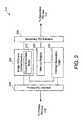
- FIG. 2shows a more detailed block diagram of the PCI bridge 112 in accordance with one embodiment of the present invention.
- the PCI bridge 112includes bridge FIFO and control circuitry 202 , a primary PCI interface 204 , a secondary PCI interface 206 , an interrupt register 208 , and an interrupt generation logic 210 .
- the PCI interfaces 204 and 206provide the bridge 112 with interface functions between the primary and secondary PCI buses 110 and 114 for communicating data and control signals.
- the primary PCI interface 204interfaces with the primary PCI bus 110 on the host side while the secondary PCI interface 206 interfaces with the secondary PCI bus 114 .
- a conventional PCI arbitermay also be provided internally between the secondary PCI interface 206 and the bridge FIFO and control circuitry 202 or externally coupled to the secondary PCI bus 114 .
- the arbiterreceives and evaluates requests for access to the secondary PCI bus from one or more PCI devices (e.g., SCSI adapter, RAID controller) attached to the secondary PCI bus 114 and grants the PCI bus to one of the requesting PCI devices as a bus master.
- the PCI arbitermay implement any well-known system-specific arbitration algorithm.
- the bridge FIFO and control circuitry 202includes a data buffer 212 .
- the data buffer 212stores posted data written from devices attached to the buses 110 and 114 for transmission to specified devices coupled to the primary and secondary PCI buses 110 and 114 .
- the secondary PCI agent 116 Awrites the data to the posted write data buffer 212 in the PCI bridge 112 .
- the secondary PCI agentthen writes to the interrupt register 208 in the PCI bridge 112 via the secondary PCI interface 206 to indicate completion of the data transfer.
- the interrupt generation logic 210is coupled to the interrupt register 208 , bridge FIFO and control circuitry 202 , and primary PCI interface 204 .
- the interrupt generation logic 210When the interrupt register 208 is written, the interrupt generation logic 210 generates and sends a message signaled interrupt to the host computer 102 via primary PCI bus 110 .
- FIG. 3shows an exemplary interrupt register 208 coupled between the secondary PCI interface 206 and the interrupt generation logic 210 in accordance with one embodiment of the present invention.
- the interrupt register 208is configured to store 16 bits of information from bit 0 (i.e., B 0 ) to bit 15 (i.e., B 15 ).
- PCI devicesmay communicate different types of interrupt messages.
- each bit in the interrupt register 208indicates an interrupt message for a specified interrupt type. Thus, up to 16 different types of interrupt messages can be communicated via the interrupt register 208 .
- each of the bits in the interrupt register 208may be associated with one of the secondary PCI devices.
- a secondary PCI devicewrites an interrupt message into an associated interrupt bit in the interrupt register 208 .
- the present inventionis illustrated using a 16-bit interrupt register, it may also employ any suitable number of bits (e.g., 8 bits, 32 bits, etc.) in the interrupt register to generate message signaled interrupts.
- the interrupt generation logic 210is configured to access the interrupt register for generating message signaled interrupts with proper ordering relative to posted write transactions.
- FIG. 4shows a more detailed schematic block diagram of the interrupt generation logic 210 in accordance with one embodiment of the present invention.
- the interrupt generation logic 210includes interrupt detection circuitry 402 , posted write registers 404 , interrupt entry logic circuitry 406 , a circular queue 408 , an interrupt message generator 410 , and posted write tracking circuitry 412 .
- the interrupt detection circuitry 402is coupled to receive the contents of the interrupt register 208 to detect an incoming interrupt and writes the number of outstanding posted writes into the posted write registers 404 , which is coupled to the interrupt detection circuitry.
- the interrupt detection circuitry 402includes a pair of registers 414 and 416 for storing interrupt_pending and need_to_queue flags for each of the bits B 0 to B 15 in the interrupt register 208 .
- the interrupt_pending register 414stores 16 interrupt_pending (IP) flag bits indicating whether an interrupt message is pending for each of the bits B 0 to B 15 in the interrupt register 208 .
- the need_to_queue register 416stores 16 need_to_queue (NQ) flag bits indicating whether the interrupts need to be queued for each of the bits B 0 to B 15 in the interrupt register 208 .
- the interrupt entry logic circuitry 406is coupled between the interrupt detection circuitry 402 and the circular queue 408 and is configured to enter the interrupt bit number into the circular queue 408 .
- the circular queue 408receives the interrupt bit number and keeps track of the order of the interrupt bits as they are received from the interrupt entry logic circuitry 406 .
- FIG. 5shows a flow chart of a method 500 performed by the interrupt detection circuitry 402 in accordance with one embodiment of the present invention.
- the interrupt detection circuitry 402determines whether an incoming interrupt has been detected. For example, whenever a secondary PCI devices writes to the interrupt register 208 , the interrupt detection circuitry 402 detects the interrupt bit number (e.g., interrupt bit position) written.
- the interrupt bit numbere.g., interrupt bit position
- the methodproceeds to operation 504 to determine if a previous occurrence of the interrupt bit is pending by referencing an associated interrupt_pending bit in the interrupt_pending register 414 . For example, if interrupt bit B 3 has been written, the interrupt detection circuitry 402 checks bit number IP 3 of the interrupt_pending register 414 . If a previous occurrence of the interrupt bit is pending, the method proceeds back to operation 502 to detect writing of another interrupt message.
- IP flag bits in the interrupt_pending register 414allows generation of a single message signaled interrupt for a detected interrupt bit instead of multiple message signaled interrupts.
- the associated IP flag bitmay indicate that a previous interrupt for the interrupt bit B 3 is still pending (i.e., queued) because the primary PCI bus may be busy.
- the PCI bridge 112waits until the primary PCI bus becomes available.
- the secondary PCI devicemay write another interrupt message into interrupt bit B 3 .
- the PCI bridge 112need not create another message signaled interrupt for the interrupt bit B 3 .
- the IP flag bitsthus eliminates generation of duplicate or multiple message signaled interrupts
- operation 504if the detected interrupt bit is not pending in the interrupt_pending register 414 , the method proceeds to operation 506 , where the IP bit associated with the detected interrupt bit is set in the interrupt_pending register 414 .
- the setting of the IP bitindicates that the interrupt is pending for the associated interrupt bit.
- the NQ bit associated with the detected interrupt bitis set in the need_to_queue register 416 in operation 508 .
- the setting of the NQ bitallows the associated interrupt bit number to be queued for entry into the circular queue 408 . For example, when more than one interrupt bit number are detected, the interrupt bit numbers are queued one at a time for entry into the circular buffer 408 . As will be discussed in more detail below, when an interrupt bit number is entered into the circular buffer 408 , the associated NQ flag bit is cleared. Once the NQ bit has been set, the number of outstanding posted writes is written, in operation 510 , into one of the posted write registers 404 associated with the detected interrupt bit. The method 500 then terminates in operation 512 .
- FIG. 6is a schematic block diagram of the posted write registers 404 for keeping track of the pending posted writes in accordance with one embodiment of the present invention.
- the posted write registers 404includes 16 registers 602 to 632 , each of which stores the number of posted writes pending for the associated interrupt bit number.
- the posted write register 602stores the number of pending posted writes for the interrupt bit B 0 while the posted write register 608 stores the number of pending posted writes for the interrupt bit B 3 .
- the number of posted write registersis preferably equal to the number of interrupt bits in the interrupt register 208 .
- the interrupt detection circuitry 402detects the writing of an interrupt bit in the interrupt register 208 , the number of pending posted writes that are outstanding is entered into a corresponding posted write register and is provided to the interrupt message generator 410 .
- the posted write registers 404are coupled to the posted write tracking circuitry 412 , which keeps track of posted writes to the primary PCI bus 110 from the PCI bridge 112 .
- the posted write tracking circuitry 412transmits a decrement signal to the posted write registers 404 .
- all posted write registers 404 with a non-zero valueare decremented by one. In this manner, the pending posted write registers 404 are used to hold the number of posted writes that must be completed before the interrupt message is generated and posted over the primary PCI bus 110 .
- FIG. 7illustrates a flow chart of a method performed by the interrupt entry logic circuitry 406 in accordance with one embodiment of the present invention.
- the interrupt entry logic circuitry 406determines whether there is an interrupt that needs to be entered into the circular queue 408 . If not, the method proceeds back to operation 702 until it is determined that an interrupt needs to be entered into the queue 408 .
- the interrupt bit numberis entered, in operation 704 , into the queue 408 at the location pointed to by an incoming_interrupt pointer in the queue 408 .
- the incoming_interrupt pointeris incremented to point to the next location in the circular queue 408 in operation 706 .
- the corresponding NQ flag bit in the need_to_queue register 416is cleared in operation 708 .
- the methodthen terminates in operation 710 .
- FIG. 8shows a more detailed schematic block diagram of the circular queue 408 in accordance with one embodiment of the present invention.
- the circular queue 408includes 16 registers 802 to 832 that are circularly linked to queue interrupt bit numbers in the order they are received.
- An incoming interrupt register 836 in the circular queue 408keeps track of the register location in which an incoming interrupt number is to be stored. Specifically, the incoming interrupt register 836 points to one of the registers 802 to 832 into which an incoming interrupt bit number from the interrupt entry logic circuitry 406 is to be stored.
- the circular queue 408increments the incoming interrupt register 836 to point to the next register in the circular chain of registers 802 to 832 . In this manner, incoming interrupt bit numbers are queued in order.
- a current interrupt pointer 834points to one of the registers 802 to 832 to keep track of the register location from which the stored interrupt bit number is sent to the interrupt message generator 410 .
- the interrupt message generator 410When the interrupt bit number is received, the interrupt message generator 410 generates a message signaled interrupt, which is sent to the primary PCI bus 110 via primary PCI interface 204 .
- registers 802 to 810may store interrupt bit numbers 5 , 3 , 2 , 0 , and 4 , respectively, in the order received.
- the current interrupt pointer 834points to register 804 , it means that the interrupt bit number 5 from register 802 has gone out to the interrupt message generator 410 for generating a message signaled interrupt.
- the depth of the queueis equal to the maximum number of unique interrupts that can be generated within the PCI bridge 112 . If the same interrupt is received before it has gone out, the new occurrence is not entered into the queue 408 since only one interrupt message needs to be generated for each interrupt bit number regardless of how many times it is received. Because the queue 408 is circular, the pointers 834 and 836 wrap around to the first entry (i.e., first entry register 802 ) once the pointers are incremented past the end of the queue (i.e., last entry register 832 ).
- FIG. 9illustrates a flow chart of a method performed by the posted write tracking circuitry 412 in accordance with one embodiment of the present invention.
- the posted write tracking circuitry 412determines whether a posted write has completed on the destination PCI bus (e.g., primary PCI bus 110 ). If not, the method proceeds back to operation 902 until a posted write has been completed on the destination PCI bus. On the other hand, when a posted write has been completed on the destination PCI bus, the method proceeds to operation 904 , where all posted write registers that are non-zero are decremented by one. The method then terminates in operation 906 .
- the destination PCI buse.g., primary PCI bus 110
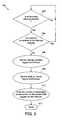
- FIG. 10shows a flow chart of a method performed by the interrupt message generator 410 in accordance with one embodiment of the present invention.
- the methodbegins in operation 1002 , where the interrupt message generator 410 determines whether a message signaled interrupt is pending, i.e., ready to be sent, by examining the interrupt_pending flag register 414 of the interrupt detection circuitry 402 .
- the methodproceeds to operation 1004 , where the interrupt message generator 410 waits for the queuing to complete by waiting for need_to_queue flag associated with the message signaled interrupt (i.e., interrupt bit number) to clear from the interrupt detection circuitry 402 .
- the interrupt message generator 410obtains an interrupt bit number from the circular buffer 408 from the location pointed to by the current interrupt pointer 834 .
- the interrupt message generator 410determines whether the pending posted write count for the interrupt bit number is zero in operation 1006 . For this purpose, the interrupt message generator 410 is coupled to the pending posted write registers 404 to access the stored number of posted writes. If the pending posted write count for the interrupt bit number is non-zero, the interrupt message generator 410 waits until the count becomes zero. When the write count is zero, the method proceeds to operation 1008 , where the interrupt message generator 410 generates a request and a message signaled interrupt for the interrupt bit number to the PCI interface for transmission to the primary PCI interface 204 . This ensures that the posting of the message signaled interrupt is delayed until all posted writes that were pending when the interrupt occurred have been posted to the primary PCI bus 110 .
- operation 1010it is determined whether the message signaled interrupt has been sent out to the primary PCI interface 110 . For example, a message signaled interrupt is sent if the primary PCI interface 110 returns a “sent” signal to the interrupt message generator 410 . In such cases, the request to the PCI interface 110 is deasserted and the interrupt_pending flag for the transmitted interrupt bit number is cleared in operation 1012 . However, if the message signaled interrupt has not been sent out, the interrupt message generator 410 waits until it has been sent out. After clearing the interrupt pending flag, the current_interrupt pointer 834 of the circular queue 408 is incremented to point to the next register location for generating the next message signaled interrupt for transmission. The method then terminates in operation 1016 .
- the present inventionthus ensures that any posted writes that were pending when an interrupt message is received from the secondary bus devices are written before generating and posting an associated message signaled interrupt.
- the pending posted write registersstore the number of posted writes that must be completed before an associated message signaled interrupt is generated and posted.
- the values in the pending posted write registersare then decremented if they are non-zero when a posted write is completed. Delaying the posting of the message signaled interrupt until all posted writes that were pending when the associated interrupt bit number has been received ensures proper ordering of message signaled interrupts relative to the posted writes.
Landscapes
- Engineering & Computer Science (AREA)
- Theoretical Computer Science (AREA)
- Physics & Mathematics (AREA)
- General Engineering & Computer Science (AREA)
- General Physics & Mathematics (AREA)
- Bus Control (AREA)
Abstract
Description
Claims (29)
Priority Applications (1)
| Application Number | Priority Date | Filing Date | Title |
|---|---|---|---|
| US09/630,341US6629179B1 (en) | 2000-07-31 | 2000-07-31 | Message signaled interrupt generating device and method |
Applications Claiming Priority (1)
| Application Number | Priority Date | Filing Date | Title |
|---|---|---|---|
| US09/630,341US6629179B1 (en) | 2000-07-31 | 2000-07-31 | Message signaled interrupt generating device and method |
Publications (1)
| Publication Number | Publication Date |
|---|---|
| US6629179B1true US6629179B1 (en) | 2003-09-30 |
Family
ID=28455102
Family Applications (1)
| Application Number | Title | Priority Date | Filing Date |
|---|---|---|---|
| US09/630,341Expired - LifetimeUS6629179B1 (en) | 2000-07-31 | 2000-07-31 | Message signaled interrupt generating device and method |
Country Status (1)
| Country | Link |
|---|---|
| US (1) | US6629179B1 (en) |
Cited By (41)
| Publication number | Priority date | Publication date | Assignee | Title |
|---|---|---|---|---|
| US20020091891A1 (en)* | 2000-08-31 | 2002-07-11 | Duncan Samuel H. | Passive release avoidance technique |
| US20030023771A1 (en)* | 2001-07-30 | 2003-01-30 | Erickson Michael John | Method for accessing scan chains and updating EEPROM-resident FPGA code through a system mangement processor and JTAG bus |
| US20030020512A1 (en)* | 2001-07-30 | 2003-01-30 | Paul Mantey | System and method for in-system programming through an on-system JTAG bridge of programmable logic devices on multiple circuit boards of a system |
| US20030023962A1 (en)* | 2001-07-30 | 2003-01-30 | Erickson Michael John | Method for just-in-time updating of programming parts |
| US20030041252A1 (en)* | 2001-08-24 | 2003-02-27 | Broadcom Corporation | Methods and apparatus for collapsing interrupts |
| US20030126029A1 (en)* | 2001-12-31 | 2003-07-03 | Jaideep Dastidar | Inter-queue ordering mechanism |
| US20030131176A1 (en)* | 2002-01-07 | 2003-07-10 | International Business Machines Corporation | Method and apparatus for passing messages through a bus-to-bus bridge while maintaining ordering |
| US20030200383A1 (en)* | 2002-04-22 | 2003-10-23 | Chui Kwong-Tak A. | Tracking non-posted writes in a system |
| US20040177126A1 (en)* | 2003-02-18 | 2004-09-09 | Chaparral Network Storage, Inc. | Broadcast bridge apparatus for transferring data to redundant memory subsystems in a storage controller |
| US20040225783A1 (en)* | 2001-07-30 | 2004-11-11 | Erickson Michael John | Bus to multiple jtag bus bridge |
| US20040225789A1 (en)* | 2003-03-28 | 2004-11-11 | International Business Machines Corporation | Method for data protection for removable recording medium |
| US20050102557A1 (en)* | 2001-09-28 | 2005-05-12 | Dot Hill Systems Corporation | Apparatus and method for adopting an orphan I/O port in a redundant storage controller |
| US20050138256A1 (en)* | 2003-12-23 | 2005-06-23 | Bolay Frederick H. | Method and apparatus for processing hot key input using operating system visible interrupt handling |
| US20050138220A1 (en)* | 2003-12-19 | 2005-06-23 | Bennett Joseph A. | Driver transparent message signaled interrupts |
| US20050273540A1 (en)* | 2004-05-11 | 2005-12-08 | Stmicroelectronics Limited | Interrupt handling system |
| US20050283554A1 (en)* | 2004-06-22 | 2005-12-22 | General Electric Company | Computer system and method for queuing interrupt messages in a device coupled to a parallel communication bus |
| US6983339B1 (en)* | 2000-09-29 | 2006-01-03 | Intel Corporation | Method and apparatus for processing interrupts of a bus |
| US20060047877A1 (en)* | 2004-08-31 | 2006-03-02 | Advanced Micro Devices, Inc. | Message based interrupt table |
| US20060106982A1 (en)* | 2001-09-28 | 2006-05-18 | Dot Hill Systems Corporation | Certified memory-to-memory data transfer between active-active raid controllers |
| US20060149878A1 (en)* | 2004-12-30 | 2006-07-06 | Carmichael Richard D | Efficient interrupt processing in systems with multiple serial protocol engines |
| US20060161709A1 (en)* | 2005-01-20 | 2006-07-20 | Dot Hill Systems Corporation | Safe message transfers on PCI-Express link from RAID controller to receiver-programmable window of partner RAID controller CPU memory |
| US20060161707A1 (en)* | 2005-01-20 | 2006-07-20 | Dot Hill Systems Corporation | Method for efficient inter-processor communication in an active-active RAID system using PCI-express links |
| US20070016710A1 (en)* | 2005-07-12 | 2007-01-18 | Arm Limited | Interrupt controller and method for handling interrupts |
| US20070067534A1 (en)* | 2005-09-16 | 2007-03-22 | Emulex Design & Manufacturing Corporation | Message signaled interrupt extended (MSI-X) auto clear and failsafe lock |
| US20080005470A1 (en)* | 2006-06-30 | 2008-01-03 | Dot Hill Systems Corporation | System and method for sharing sata drives in active-active raid controller system |
| US7340555B2 (en) | 2001-09-28 | 2008-03-04 | Dot Hill Systems Corporation | RAID system for performing efficient mirrored posted-write operations |
| US7363412B1 (en)* | 2004-03-01 | 2008-04-22 | Cisco Technology, Inc. | Interrupting a microprocessor after a data transmission is complete |
| US20080201616A1 (en)* | 2007-02-20 | 2008-08-21 | Dot Hill Systems Corporation | Redundant storage controller system with enhanced failure analysis capability |
| US20080219279A1 (en)* | 2007-03-06 | 2008-09-11 | Yen Hsiang Chew | Scalable and configurable queue management for network packet traffic quality of service |
| US20080276027A1 (en)* | 2007-05-01 | 2008-11-06 | Hagita Yasuharu | Interrupt control apparatus, bus bridge, bus switch, image processing apparatus, and interrupt control method |
| US20090106469A1 (en)* | 2007-10-22 | 2009-04-23 | Sandisk Corporation | Signaling an interrupt request through daisy chained devices |
| US20090235004A1 (en)* | 2008-03-14 | 2009-09-17 | International Business Machines Corporation | Message Signal Interrupt Efficiency Improvement |
| WO2009134218A1 (en)* | 2008-04-28 | 2009-11-05 | Hewlett-Packard Development Company, L.P. | Virtual-interrupt-mode interface and method for virtualizing an interrupt mode |
| US20100082866A1 (en)* | 2008-09-30 | 2010-04-01 | White Bryan R | Providing a set aside mechanism for posted interrupt transactions |
| US20110302349A1 (en)* | 2010-06-02 | 2011-12-08 | Griggs Aric W | Method and system to improve the operations of an integrated non-transparent bridge device |
| US20130198432A1 (en)* | 2011-11-30 | 2013-08-01 | Marvell World Trade Ltd. | Interrupt handling systems and methods for pcie bridges with multiple buses |
| US20140122760A1 (en)* | 2012-10-26 | 2014-05-01 | Arm Limited | Communication of message signalled interrupts |
| US9146776B1 (en)* | 2011-08-16 | 2015-09-29 | Marvell International Ltd. | Systems and methods for controlling flow of message signaled interrupts |
| US9311243B2 (en) | 2012-11-30 | 2016-04-12 | Intel Corporation | Emulated message signaled interrupts in multiprocessor systems |
| CN112363763A (en)* | 2020-11-13 | 2021-02-12 | 山东云海国创云计算装备产业创新中心有限公司 | Data processing method, device and computer readable storage medium |
| CN114026549A (en)* | 2019-11-05 | 2022-02-08 | 深圳市汇顶科技股份有限公司 | Method and apparatus for aborting blocking bus accesses between a host controller and connected peripherals |
Citations (4)
| Publication number | Priority date | Publication date | Assignee | Title |
|---|---|---|---|---|
| US5692200A (en)* | 1995-10-16 | 1997-11-25 | Compaq Computer Corporation | Bridge circuit for preventing data incoherency by holding off propagation of data transfer completion interrupts until data clears the bridge circuit |
| US6253275B1 (en)* | 1998-11-25 | 2001-06-26 | Advanced Micro Devices, Inc. | Interrupt gating method for PCI bridges |
| US6370607B1 (en)* | 1999-04-13 | 2002-04-09 | Advanced Micro Devices, Inc. | Automatic disabling of interrupts upon entry into interrupt service routine |
| US6389526B1 (en)* | 1999-08-24 | 2002-05-14 | Advanced Micro Devices, Inc. | Circuit and method for selectively stalling interrupt requests initiated by devices coupled to a multiprocessor system |
- 2000
- 2000-07-31USUS09/630,341patent/US6629179B1/ennot_activeExpired - Lifetime
Patent Citations (4)
| Publication number | Priority date | Publication date | Assignee | Title |
|---|---|---|---|---|
| US5692200A (en)* | 1995-10-16 | 1997-11-25 | Compaq Computer Corporation | Bridge circuit for preventing data incoherency by holding off propagation of data transfer completion interrupts until data clears the bridge circuit |
| US6253275B1 (en)* | 1998-11-25 | 2001-06-26 | Advanced Micro Devices, Inc. | Interrupt gating method for PCI bridges |
| US6370607B1 (en)* | 1999-04-13 | 2002-04-09 | Advanced Micro Devices, Inc. | Automatic disabling of interrupts upon entry into interrupt service routine |
| US6389526B1 (en)* | 1999-08-24 | 2002-05-14 | Advanced Micro Devices, Inc. | Circuit and method for selectively stalling interrupt requests initiated by devices coupled to a multiprocessor system |
Non-Patent Citations (1)
| Title |
|---|
| Unknown, "PCI Local Bus Specification Revision 2.2," Dec. 18, 1998, PCI Special Interest Group, 322 pages. |
Cited By (87)
| Publication number | Priority date | Publication date | Assignee | Title |
|---|---|---|---|---|
| US20020091891A1 (en)* | 2000-08-31 | 2002-07-11 | Duncan Samuel H. | Passive release avoidance technique |
| US7024509B2 (en)* | 2000-08-31 | 2006-04-04 | Hewlett-Packard Development Company, L.P. | Passive release avoidance technique |
| US6983339B1 (en)* | 2000-09-29 | 2006-01-03 | Intel Corporation | Method and apparatus for processing interrupts of a bus |
| US6883109B2 (en) | 2001-07-30 | 2005-04-19 | Hewlett-Packard Development Company, L.P. | Method for accessing scan chains and updating EEPROM-resident FPGA code through a system management processor and JTAG bus |
| US20030023771A1 (en)* | 2001-07-30 | 2003-01-30 | Erickson Michael John | Method for accessing scan chains and updating EEPROM-resident FPGA code through a system mangement processor and JTAG bus |
| US6918027B2 (en) | 2001-07-30 | 2005-07-12 | Hewlett-Packard Development Company, L.P. | System and method for in-system programming through an on-system JTAG bridge of programmable logic devices on multiple circuit boards of a system |
| US6954929B2 (en) | 2001-07-30 | 2005-10-11 | Hewlett-Packard Development Company, L.P. | Method for just-in-time updating of programming parts |
| US20030020512A1 (en)* | 2001-07-30 | 2003-01-30 | Paul Mantey | System and method for in-system programming through an on-system JTAG bridge of programmable logic devices on multiple circuit boards of a system |
| US20030023962A1 (en)* | 2001-07-30 | 2003-01-30 | Erickson Michael John | Method for just-in-time updating of programming parts |
| US20040225783A1 (en)* | 2001-07-30 | 2004-11-11 | Erickson Michael John | Bus to multiple jtag bus bridge |
| US20030041252A1 (en)* | 2001-08-24 | 2003-02-27 | Broadcom Corporation | Methods and apparatus for collapsing interrupts |
| US7861104B2 (en)* | 2001-08-24 | 2010-12-28 | Broadcom Corporation | Methods and apparatus for collapsing interrupts |
| US20060106982A1 (en)* | 2001-09-28 | 2006-05-18 | Dot Hill Systems Corporation | Certified memory-to-memory data transfer between active-active raid controllers |
| US20060282701A1 (en)* | 2001-09-28 | 2006-12-14 | Dot Hill Systems Corporation | Method for adopting an orphan i/o port in a redundant storage controller |
| US7558897B2 (en) | 2001-09-28 | 2009-07-07 | Dot Hill Systems Corporation | Method for adopting an orphan I/O port in a redundant storage controller |
| US7340555B2 (en) | 2001-09-28 | 2008-03-04 | Dot Hill Systems Corporation | RAID system for performing efficient mirrored posted-write operations |
| US7536495B2 (en) | 2001-09-28 | 2009-05-19 | Dot Hill Systems Corporation | Certified memory-to-memory data transfer between active-active raid controllers |
| US7146448B2 (en) | 2001-09-28 | 2006-12-05 | Dot Hill Systems Corporation | Apparatus and method for adopting an orphan I/O port in a redundant storage controller |
| US20050102557A1 (en)* | 2001-09-28 | 2005-05-12 | Dot Hill Systems Corporation | Apparatus and method for adopting an orphan I/O port in a redundant storage controller |
| US20030126029A1 (en)* | 2001-12-31 | 2003-07-03 | Jaideep Dastidar | Inter-queue ordering mechanism |
| US7139859B2 (en)* | 2001-12-31 | 2006-11-21 | Hewlett-Packard Development Company, L.P. | Inter-queue ordering mechanism |
| US6801977B2 (en)* | 2002-01-07 | 2004-10-05 | International Business Machines Corporation | Method and apparatus for passing messages through a bus-to-bus bridge while maintaining ordering |
| US20030131176A1 (en)* | 2002-01-07 | 2003-07-10 | International Business Machines Corporation | Method and apparatus for passing messages through a bus-to-bus bridge while maintaining ordering |
| US7003615B2 (en)* | 2002-04-22 | 2006-02-21 | Broadcom Corporation | Tracking a non-posted writes in a system using a storage location to store a write response indicator when the non-posted write has reached a target device |
| US20030200383A1 (en)* | 2002-04-22 | 2003-10-23 | Chui Kwong-Tak A. | Tracking non-posted writes in a system |
| US20040177126A1 (en)* | 2003-02-18 | 2004-09-09 | Chaparral Network Storage, Inc. | Broadcast bridge apparatus for transferring data to redundant memory subsystems in a storage controller |
| US7143227B2 (en)* | 2003-02-18 | 2006-11-28 | Dot Hill Systems Corporation | Broadcast bridge apparatus for transferring data to redundant memory subsystems in a storage controller |
| US20040225789A1 (en)* | 2003-03-28 | 2004-11-11 | International Business Machines Corporation | Method for data protection for removable recording medium |
| US7321945B2 (en)* | 2003-03-28 | 2008-01-22 | Lenovo (Singapore) Pte. Ltd. | Interrupt control device sending data to a processor at an optimized time |
| US8166223B2 (en) | 2003-12-19 | 2012-04-24 | Intel Corporation | Apparatuses to provide a message signaled interrupt to generate a PCI express interrupt |
| EP2112600A3 (en)* | 2003-12-19 | 2010-08-11 | Intel Corporation | Driver transparent message signaled interrupts |
| WO2005066815A1 (en)* | 2003-12-19 | 2005-07-21 | Intel Corporation | Driver transparent message signaled interrupts |
| US20100095038A1 (en)* | 2003-12-19 | 2010-04-15 | Bennett Joseph A | Driver Transparent Message Signaled Interrupts |
| US20080263250A1 (en)* | 2003-12-19 | 2008-10-23 | Bennett Joseph A | Driver transparent message signaled interrupts |
| US7743194B2 (en)* | 2003-12-19 | 2010-06-22 | Intel Corporation | Driver transparent message signaled interrupts |
| US7409483B2 (en)* | 2003-12-19 | 2008-08-05 | Intel Corporation | Methods and apparatuses to provide message signaled interrupts to level-sensitive drivers |
| US20050138220A1 (en)* | 2003-12-19 | 2005-06-23 | Bennett Joseph A. | Driver transparent message signaled interrupts |
| US20050138256A1 (en)* | 2003-12-23 | 2005-06-23 | Bolay Frederick H. | Method and apparatus for processing hot key input using operating system visible interrupt handling |
| US7363412B1 (en)* | 2004-03-01 | 2008-04-22 | Cisco Technology, Inc. | Interrupting a microprocessor after a data transmission is complete |
| US20050273540A1 (en)* | 2004-05-11 | 2005-12-08 | Stmicroelectronics Limited | Interrupt handling system |
| US20050283554A1 (en)* | 2004-06-22 | 2005-12-22 | General Electric Company | Computer system and method for queuing interrupt messages in a device coupled to a parallel communication bus |
| US20060047877A1 (en)* | 2004-08-31 | 2006-03-02 | Advanced Micro Devices, Inc. | Message based interrupt table |
| US7257658B2 (en)* | 2004-08-31 | 2007-08-14 | Advanced Micro Devices, Inc. | Message based interrupt table |
| US20060149878A1 (en)* | 2004-12-30 | 2006-07-06 | Carmichael Richard D | Efficient interrupt processing in systems with multiple serial protocol engines |
| US7315911B2 (en) | 2005-01-20 | 2008-01-01 | Dot Hill Systems Corporation | Method for efficient inter-processor communication in an active-active RAID system using PCI-express links |
| US20060161707A1 (en)* | 2005-01-20 | 2006-07-20 | Dot Hill Systems Corporation | Method for efficient inter-processor communication in an active-active RAID system using PCI-express links |
| US20060161709A1 (en)* | 2005-01-20 | 2006-07-20 | Dot Hill Systems Corporation | Safe message transfers on PCI-Express link from RAID controller to receiver-programmable window of partner RAID controller CPU memory |
| US7543096B2 (en) | 2005-01-20 | 2009-06-02 | Dot Hill Systems Corporation | Safe message transfers on PCI-Express link from RAID controller to receiver-programmable window of partner RAID controller CPU memory |
| US7805557B2 (en)* | 2005-07-12 | 2010-09-28 | Arm Limited | Interrupt controller and method for handling interrupts |
| US20070016710A1 (en)* | 2005-07-12 | 2007-01-18 | Arm Limited | Interrupt controller and method for handling interrupts |
| US20070067534A1 (en)* | 2005-09-16 | 2007-03-22 | Emulex Design & Manufacturing Corporation | Message signaled interrupt extended (MSI-X) auto clear and failsafe lock |
| US7565471B2 (en)* | 2005-09-16 | 2009-07-21 | Emulex Design & Manufacturing Corporation | Message signaled interrupt extended (MSI-X) auto clear and failsafe lock |
| US20080005470A1 (en)* | 2006-06-30 | 2008-01-03 | Dot Hill Systems Corporation | System and method for sharing sata drives in active-active raid controller system |
| US7536508B2 (en) | 2006-06-30 | 2009-05-19 | Dot Hill Systems Corporation | System and method for sharing SATA drives in active-active RAID controller system |
| US20080201616A1 (en)* | 2007-02-20 | 2008-08-21 | Dot Hill Systems Corporation | Redundant storage controller system with enhanced failure analysis capability |
| US7681089B2 (en) | 2007-02-20 | 2010-03-16 | Dot Hill Systems Corporation | Redundant storage controller system with enhanced failure analysis capability |
| US20080219279A1 (en)* | 2007-03-06 | 2008-09-11 | Yen Hsiang Chew | Scalable and configurable queue management for network packet traffic quality of service |
| US7710989B2 (en)* | 2007-03-06 | 2010-05-04 | Intel Corporation | Scalable and configurable queue management for network packet traffic quality of service |
| US20080276027A1 (en)* | 2007-05-01 | 2008-11-06 | Hagita Yasuharu | Interrupt control apparatus, bus bridge, bus switch, image processing apparatus, and interrupt control method |
| US7805556B2 (en)* | 2007-05-01 | 2010-09-28 | Ricoh Company, Ltd. | Interrupt control apparatus, bus bridge, bus switch, image processing apparatus, and interrupt control method |
| US7752353B2 (en)* | 2007-10-22 | 2010-07-06 | Sandisk Il Ltd. | Signaling an interrupt request through daisy chained devices |
| US20090106469A1 (en)* | 2007-10-22 | 2009-04-23 | Sandisk Corporation | Signaling an interrupt request through daisy chained devices |
| US20090235004A1 (en)* | 2008-03-14 | 2009-09-17 | International Business Machines Corporation | Message Signal Interrupt Efficiency Improvement |
| CN102016812A (en)* | 2008-04-28 | 2011-04-13 | 惠普开发有限公司 | Virtual interrupt mode interface and method for virtualizing interrupt mode |
| US20110047309A1 (en)* | 2008-04-28 | 2011-02-24 | Brinkmann Hubert E | Virtual-interrupt-mode interface and method for virtualizing an interrupt mode |
| US9037768B2 (en) | 2008-04-28 | 2015-05-19 | Hewlett-Packard Development Company, L.P. | Virtual-interrupt-mode interface and method for virtualizing an interrupt mode |
| WO2009134218A1 (en)* | 2008-04-28 | 2009-11-05 | Hewlett-Packard Development Company, L.P. | Virtual-interrupt-mode interface and method for virtualizing an interrupt mode |
| CN102016812B (en)* | 2008-04-28 | 2014-06-11 | 惠普开发有限公司 | Virtual interrupt mode interface and method for virtualizing interrupt mode |
| CN101916236A (en)* | 2008-09-30 | 2010-12-15 | 英特尔公司 | Providing a set aside mechanism for posted interrupt transactions |
| US7861024B2 (en)* | 2008-09-30 | 2010-12-28 | Intel Corporation | Providing a set aside mechanism for posted interrupt transactions |
| US20100082866A1 (en)* | 2008-09-30 | 2010-04-01 | White Bryan R | Providing a set aside mechanism for posted interrupt transactions |
| CN101916236B (en)* | 2008-09-30 | 2013-06-26 | 英特尔公司 | Providing a set aside mechanism for posted interrupt transactions |
| EP2577491A4 (en)* | 2010-06-02 | 2014-01-22 | Intel Corp | Method and system to improve the operations of an integrated non-transparent bridge device |
| US20110302349A1 (en)* | 2010-06-02 | 2011-12-08 | Griggs Aric W | Method and system to improve the operations of an integrated non-transparent bridge device |
| CN103038758B (en)* | 2010-06-02 | 2015-09-09 | 英特尔公司 | Improve the method and system of the operation of integrated non-transparent bridge equipment |
| CN103038758A (en)* | 2010-06-02 | 2013-04-10 | 英特尔公司 | Method and system to improve the operations of an integrated non-transparent bridge device |
| US8589613B2 (en)* | 2010-06-02 | 2013-11-19 | Intel Corporation | Method and system to improve the operations of an integrated non-transparent bridge device |
| US9146776B1 (en)* | 2011-08-16 | 2015-09-29 | Marvell International Ltd. | Systems and methods for controlling flow of message signaled interrupts |
| US9128920B2 (en)* | 2011-11-30 | 2015-09-08 | Marvell World Trade Ltd. | Interrupt handling systems and methods for PCIE bridges with multiple buses |
| US20130198432A1 (en)* | 2011-11-30 | 2013-08-01 | Marvell World Trade Ltd. | Interrupt handling systems and methods for pcie bridges with multiple buses |
| US8924615B2 (en)* | 2012-10-26 | 2014-12-30 | Arm Limited | Communication of message signalled interrupts |
| US20140122760A1 (en)* | 2012-10-26 | 2014-05-01 | Arm Limited | Communication of message signalled interrupts |
| TWI573076B (en)* | 2012-10-26 | 2017-03-01 | Arm股份有限公司 | Communication of message signalled interrupts |
| US9311243B2 (en) | 2012-11-30 | 2016-04-12 | Intel Corporation | Emulated message signaled interrupts in multiprocessor systems |
| CN114026549A (en)* | 2019-11-05 | 2022-02-08 | 深圳市汇顶科技股份有限公司 | Method and apparatus for aborting blocking bus accesses between a host controller and connected peripherals |
| CN114026549B (en)* | 2019-11-05 | 2023-11-14 | 深圳市汇顶科技股份有限公司 | Method and apparatus for aborting blocking bus accesses between a host controller and connected peripheral devices |
| CN112363763A (en)* | 2020-11-13 | 2021-02-12 | 山东云海国创云计算装备产业创新中心有限公司 | Data processing method, device and computer readable storage medium |
Similar Documents
| Publication | Publication Date | Title |
|---|---|---|
| US6629179B1 (en) | Message signaled interrupt generating device and method | |
| CA2186598C (en) | Method and apparatus for maintaining transaction ordering and supporting deferred replies in a bus bridge | |
| US7418537B2 (en) | Deadlock avoidance in a bus fabric | |
| US8244950B2 (en) | Buffering non-posted read commands and responses | |
| KR100253753B1 (en) | Method and apparatus for performing deferred transactions | |
| US5761444A (en) | Method and apparatus for dynamically deferring transactions | |
| US5696910A (en) | Method and apparatus for tracking transactions in a pipelined bus | |
| US6138192A (en) | Delivering a request to write or read data before delivering an earlier write request | |
| US5870627A (en) | System for managing direct memory access transfer in a multi-channel system using circular descriptor queue, descriptor FIFO, and receive status queue | |
| US20040024948A1 (en) | Response reordering mechanism | |
| US6804673B2 (en) | Access assurance for remote memory access over network | |
| US6636927B1 (en) | Bridge device for transferring data using master-specific prefetch sizes | |
| US7016994B2 (en) | Retry mechanism for blocking interfaces | |
| US6675251B1 (en) | Bridge device for connecting multiple devices to one slot | |
| US6889266B1 (en) | Method for delivering packet boundary or other metadata to and from a device using direct memory controller | |
| US7181561B2 (en) | Ordering rule controlled command storage | |
| US20020184453A1 (en) | Data bus system including posted reads and writes | |
| US6766386B2 (en) | Method and interface for improved efficiency in performing bus-to-bus read data transfers | |
| JP3600536B2 (en) | Method and system for limiting corruption of write data and PCI bus system | |
| US5923857A (en) | Method and apparatus for ordering writeback data transfers on a bus | |
| JP3417448B2 (en) | Information processing system | |
| JPH08314854A (en) | Data transfer system and related apparatus | |
| US20060106957A1 (en) | Method and system for performance enhancement in a polled data storage environment | |
| JPS6255167B2 (en) | ||
| HK1016300B (en) | Dynamic deferred transaction mechanism |
Legal Events
| Date | Code | Title | Description |
|---|---|---|---|
| AS | Assignment | Owner name:ADAPTEC, INC., CALIFORNIA Free format text:ASSIGNMENT OF ASSIGNORS INTEREST;ASSIGNOR:BASHFORD, PATRICK R.;REEL/FRAME:010994/0983 Effective date:20000726 | |
| STCF | Information on status: patent grant | Free format text:PATENTED CASE | |
| FPAY | Fee payment | Year of fee payment:4 | |
| FEPP | Fee payment procedure | Free format text:PAT HOLDER CLAIMS SMALL ENTITY STATUS, ENTITY STATUS SET TO SMALL (ORIGINAL EVENT CODE: LTOS); ENTITY STATUS OF PATENT OWNER: LARGE ENTITY | |
| FPAY | Fee payment | Year of fee payment:8 | |
| AS | Assignment | Owner name:HUPPER ISLAND LLC, DELAWARE Free format text:ASSIGNMENT OF ASSIGNORS INTEREST;ASSIGNOR:ADPT CORPORATION;REEL/FRAME:026459/0871 Effective date:20110601 | |
| FEPP | Fee payment procedure | Free format text:PAYOR NUMBER ASSIGNED (ORIGINAL EVENT CODE: ASPN); ENTITY STATUS OF PATENT OWNER: LARGE ENTITY Free format text:PAT HOLDER NO LONGER CLAIMS SMALL ENTITY STATUS, ENTITY STATUS SET TO UNDISCOUNTED (ORIGINAL EVENT CODE: STOL); ENTITY STATUS OF PATENT OWNER: LARGE ENTITY | |
| AS | Assignment | Owner name:RPX CORPORATION, CALIFORNIA Free format text:ASSIGNMENT OF ASSIGNORS INTEREST;ASSIGNOR:HUPPER ISLAND LLC;REEL/FRAME:028142/0922 Effective date:20120420 | |
| FPAY | Fee payment | Year of fee payment:12 | |
| AS | Assignment | Owner name:ADPT CORPORATION, CALIFORNIA Free format text:MERGER AND CHANGE OF NAME;ASSIGNORS:ADPT CORPORATION;ADAPTEC, INC.;REEL/FRAME:046268/0592 Effective date:20100621 | |
| AS | Assignment | Owner name:JEFFERIES FINANCE LLC, NEW YORK Free format text:SECURITY INTEREST;ASSIGNOR:RPX CORPORATION;REEL/FRAME:046486/0433 Effective date:20180619 | |
| AS | Assignment | Owner name:BARINGS FINANCE LLC, AS COLLATERAL AGENT, NORTH CAROLINA Free format text:PATENT SECURITY AGREEMENT;ASSIGNORS:RPX CLEARINGHOUSE LLC;RPX CORPORATION;REEL/FRAME:054198/0029 Effective date:20201023 Owner name:BARINGS FINANCE LLC, AS COLLATERAL AGENT, NORTH CAROLINA Free format text:PATENT SECURITY AGREEMENT;ASSIGNORS:RPX CLEARINGHOUSE LLC;RPX CORPORATION;REEL/FRAME:054244/0566 Effective date:20200823 | |
| AS | Assignment | Owner name:RPX CORPORATION, CALIFORNIA Free format text:RELEASE BY SECURED PARTY;ASSIGNOR:JEFFERIES FINANCE LLC;REEL/FRAME:054486/0422 Effective date:20201023 |