US6628764B1 - System for requesting service of a vending machine - Google Patents
System for requesting service of a vending machineDownload PDFInfo
- Publication number
- US6628764B1 US6628764B1US09/558,030US55803000AUS6628764B1US 6628764 B1US6628764 B1US 6628764B1US 55803000 AUS55803000 AUS 55803000AUS 6628764 B1US6628764 B1US 6628764B1
- Authority
- US
- United States
- Prior art keywords
- transceiver
- signal
- central station
- service
- vending machine
- Prior art date
- Legal status (The legal status is an assumption and is not a legal conclusion. Google has not performed a legal analysis and makes no representation as to the accuracy of the status listed.)
- Expired - Lifetime
Links
Images


Classifications
- G—PHYSICS
- G06—COMPUTING OR CALCULATING; COUNTING
- G06Q—INFORMATION AND COMMUNICATION TECHNOLOGY [ICT] SPECIALLY ADAPTED FOR ADMINISTRATIVE, COMMERCIAL, FINANCIAL, MANAGERIAL OR SUPERVISORY PURPOSES; SYSTEMS OR METHODS SPECIALLY ADAPTED FOR ADMINISTRATIVE, COMMERCIAL, FINANCIAL, MANAGERIAL OR SUPERVISORY PURPOSES, NOT OTHERWISE PROVIDED FOR
- G06Q20/00—Payment architectures, schemes or protocols
- G06Q20/02—Payment architectures, schemes or protocols involving a neutral party, e.g. certification authority, notary or trusted third party [TTP]
- G—PHYSICS
- G06—COMPUTING OR CALCULATING; COUNTING
- G06Q—INFORMATION AND COMMUNICATION TECHNOLOGY [ICT] SPECIALLY ADAPTED FOR ADMINISTRATIVE, COMMERCIAL, FINANCIAL, MANAGERIAL OR SUPERVISORY PURPOSES; SYSTEMS OR METHODS SPECIALLY ADAPTED FOR ADMINISTRATIVE, COMMERCIAL, FINANCIAL, MANAGERIAL OR SUPERVISORY PURPOSES, NOT OTHERWISE PROVIDED FOR
- G06Q20/00—Payment architectures, schemes or protocols
- G06Q20/04—Payment circuits
- G—PHYSICS
- G07—CHECKING-DEVICES
- G07F—COIN-FREED OR LIKE APPARATUS
- G07F17/00—Coin-freed apparatus for hiring articles; Coin-freed facilities or services
- G07F17/0014—Coin-freed apparatus for hiring articles; Coin-freed facilities or services for vending, access and use of specific services not covered anywhere else in G07F17/00
- G—PHYSICS
- G07—CHECKING-DEVICES
- G07F—COIN-FREED OR LIKE APPARATUS
- G07F5/00—Coin-actuated mechanisms; Interlocks
- G07F5/18—Coin-actuated mechanisms; Interlocks specially adapted for controlling several coin-freed apparatus from one place
- G—PHYSICS
- G07—CHECKING-DEVICES
- G07F—COIN-FREED OR LIKE APPARATUS
- G07F9/00—Details other than those peculiar to special kinds or types of apparatus
- G07F9/001—Interfacing with vending machines using mobile or wearable devices
- G—PHYSICS
- G07—CHECKING-DEVICES
- G07F—COIN-FREED OR LIKE APPARATUS
- G07F9/00—Details other than those peculiar to special kinds or types of apparatus
- G07F9/002—Vending machines being part of a centrally controlled network of vending machines
- G—PHYSICS
- G07—CHECKING-DEVICES
- G07F—COIN-FREED OR LIKE APPARATUS
- G07F9/00—Details other than those peculiar to special kinds or types of apparatus
- G07F9/02—Devices for alarm or indication, e.g. when empty; Advertising arrangements in coin-freed apparatus
- G—PHYSICS
- G07—CHECKING-DEVICES
- G07F—COIN-FREED OR LIKE APPARATUS
- G07F9/00—Details other than those peculiar to special kinds or types of apparatus
- G07F9/02—Devices for alarm or indication, e.g. when empty; Advertising arrangements in coin-freed apparatus
- G07F9/026—Devices for alarm or indication, e.g. when empty; Advertising arrangements in coin-freed apparatus for alarm, monitoring and auditing in vending machines or means for indication, e.g. when empty
Definitions
- the present inventiongenerally relates to transceivers, and more particularly to a general purpose bi-directional radio frequency (RF) transceiver integrated in a vending machine for communicating information to a remote location.
- RFradio frequency
- vending machinesAs is known, there are a wide variety of vending machines, including those that dispense soft drinks, juices, snacks, cigarettes, candy, etc. In accordance with the general operation of these devices, a patron inserts money into a machine and the machine dispenses some sort of product. In addition to the items listed above, additional products may include ice cream, tickets, tokens, money (e.g., money changers), etc.
- vending machineFor purposes of this application, the term “vending machine” is to be accorded a broad definition.
- vending machinesinclude, but are not limited to, machines that typically accept currency (either in the form of cash, credit, bank, or debit cards) and dispense some sort of product. Vending machines, however, within the scope of the term as used herein, need not require direct payment into the machine, but may simply be a machine that dispenses an article of inventory.
- vending machinesmay become inoperable (at least temporarily). For example, the machine may run out of one or more products, it may run out of change, or other problems may arise. Typically, these problems are addressed by sending a person to periodically restock the machines, or check them for proper functionality. However, this method of maintenance and/or repair is inefficient, since the machines may not need restocking or servicing. At other times, the machines may have been out of order or out of stock for some period of time before the condition is observed in the periodic restock or service run. Indeed, it is relatively expensive to employ an individual to make these periodic status checks. Also, a machine may be disabled or otherwise in need of service for an undesirably lengthy period of time between service checks, before the service condition is noted and reported.
- U.S. Pat. No. 5,207,784discloses an inventory control system for a vending machine. That patent discloses a system that maintains an accurate running count of products maintained with a vending machine, at any given time. This count, or inventory status, may be communicated to an inventory control center at any given time, via phone lines. As specifically disclosed in that patent, various vending machines are connected to an inventory control center by way of telephone lines. The '784 patent does not specify whether the telephone lines of that system are leased lines or whether they communicate to the control center through the public switched telephone network (PSTN). Nevertheless, the patent does teach that the phone lines are directly connected to the vending machines (see FIG. 1 and related discussion), and that the communication is performed by a modem disposed within each vending machine.
- PSTNpublic switched telephone network
- the system of the '784 patenteliminates the need for a person to periodically check the machine(s) to determine whether they need to be restocked, it nevertheless suffers from other shortcomings.
- the system of the '784 patentrequires a phone line to be run directly to the vending machine(s). This limits the placement/location of such machines to locations where phone lines (and taps) presently exist, or requires the added expense of paying a telephone service provider to run and maintain a phone line for each machine.
- the system of the '784 patentdoes not address the problem of system failures. When machines malfunction (for any of a variety of reasons), the problem must be manually detected and reported to the vending machine owner (or management company) so that an appropriate repair technician may be dispatched to service the machine. Valuable time and sales may be lost before the condition is discovered and reported.
- the system disclosed in the '223 patentis a system for monitoring the inventory of ice in an ice dispensing machine (another type of vending machine—even though it may not require direct payment into the machine).
- the systemdetects a low threshold of product inventory and reports the condition to the ice supplier.
- the patentspecifically teaches that the manner of reporting may “be by phone over either ground lines or cellular telephony, or by satellite, by radio transmission, or by local network.”
- the method of communicationis directly to the supplier.
- the systemlike that disclosed in the '784 patent does not address equipment failure. Thus, a mechanical failure must be manually detected and reported.
- the present inventionis generally directed to a vending machine that utilizes a multi-function bi-directional transceiver for use in an automated system for monitoring and servicing remotely located vending machines.
- the systemincludes a transmitter disposed at a first location and configured to transmit a signal containing an instruction code to a bi-directional transceiver.
- the instruction codeuniquely identifies an instruction to be carried out.
- the transmittertransmits a relatively low-power radio-frequency electromagnetic signal.
- the systemfurther includes a bi-directional transceiver disposed remotely from the transmitter (but within range of the transmitted signal) configured to receive the transmitted signal.
- the bi-directional transceiver circuitincludes a line interface circuit configured to interface with a telephone line that is part of the public-switched telephone network (PSTN) to initiate a phone call over the telephone line.
- the bi-directional transceiverfurther includes a controller configured to control both the reception of the transmitted signal and to control the communication of information over the telephone line.
- the systemincludes a central station remotely located from said bi-directional transceiver but being in communication with the bi-directional transceiver via the PSTN.
- the central stationfurther includes a decoder configured to decode the instruction code.
- the system summarized aboveprovides an extremely robust and flexible platform for providing general purpose communications to a central location.
- the term “general purpose”may also be referred to as an “open ended” platform that may be readily adapted for a wide variety of uses.
- the instruction codeis a relatively small data value that may be decoded to define a wide variety of functions. For example, an instruction code a single byte (eight bits) in size may define up to two hundred fifty six different functions or instructions. Similarly, an instruction code two bytes in size may define over sixty-five thousand (2 16 ) functions or instructions.
- the transmittertransmits the instruction code, perhaps along with other information, to a bi-directional transceiver located remotely, but generally nearby.
- the bi-directional transceiverwhich will preferably be integrated into a pay-type public telephone (but which can be integrated into virtually any telephone or other device having access to the PSTN), receives the transmitted information including the instruction code, and communicates this information to a predetermined location over the PSTN.
- the bi-directional transceiveris configured with a controller or other appropriate component to place a call to a predetermined phone number.
- the instruction codemay be communicated (by modem) to the predetermined location.
- the predetermined location(which may be a central dispatch location) then decodes the instruction code to identify the function or instruction that corresponds to the code, and further initiates an appropriate response.
- the predetermined locationmay be a computer integrated on a wide area network such as the Internet.
- the computermay be configured to receive and compile vending machine status information that may be periodically accessed and acted upon accordingly.
- the computermay be configured with software that may further communicate critical conditions by way of Email, page, voicemail, etc., to an appropriate local service technician.
- a sensor within the vending machinemay make this determination and signal the transmitter accordingly.
- the transmitterthen broadcasts a transmission that includes an instruction code that corresponds to the low product alert.
- the bi-directional transceiverreceives the broadcast transmission and communicates this information to a predetermined phone number.
- the predetermined phone numbermay also be communicated from the transmitter to the bi-directional transceiver along with the instruction code. Assuming that the predetermined number corresponds to a central dispatch center, the center answers the phone call placed by the bi-directional transceiver and receives the instruction code.
- the centermay be configured to generate an Email message or pager message to instruct appropriate service personnel of the supply request.
- the central dispatch centermay comprise a gateway connected to a wide area computer network such as the Internet.
- the central dispatch centermay take the form of an appropriately configured computer and database.
- the transceiverincludes a receiver circuit for receiving a signal transmitted from a remotely located transmitter or another transceiver.
- the transceiveralso includes a transmitter that is configured to communicate information over a phone line, comprising a portion of the PSTN.
- the transceiverincludes a controller that configures acquired information from the receiver circuit, initiates a phone call to a predetermined location, and transmits the acquired information over the PSTN to the called location.
- the RF transceiversinclude a receiver circuit for receiving a signal transmitted from a remotely located transmitter or transceiver.
- the RF transceiveralso includes a transmitter that is configured to communicate with other RF transceivers. Integration of the RF transceivers into a number of closely located vending and/or service machines enables the RF transceivers to act as repeaters to transfer appropriate service condition information until the service condition signal reaches a transceiver that is integrated with the PSTN. Once the service condition signal reaches a transceiver that is integrated with the PSTN, the signal information is configured along with service information from other closely related machines and a call is initiated to the central station.
- one or more of the closely located remote RF transceiversare integrated with cellular transmitters.
- the cellular transmittersenable each individual vending/service machine configured in this manner to communicate directly with the central station via the local cellular network and the PSTN.
- the cellular transmitterspermit the placement of vending/service machines in locations that do not have access to pay phones configured with a transceiver or locations that do not have telephone lines but are within a cellular telephone network's range.
- the systemincludes a set of sensors disposed within a vending machine.
- the sensorsare configured to detect a variety of service conditions, including products being low or out of stock, as well as, vending machine out of order conditions.
- the sensorsgenerate output signals that are input to a transmitter or bi-directional transceiver.
- the signals received from the sensorsare integrated into a message that includes an instruction code.
- the instruction codeis communicated via transmitters or transceivers to a transceiver integrated with the PSTN.
- the transceiverincludes circuitry capable of establishing a connection and communicating the instruction codes from multiple vending machines with a central station.
- a sensor within the vending machinemakes this determination and signals the transmitter accordingly.
- the transmitterthen broadcasts a transmission that includes an instruction code that corresponds to the low product alert.
- the transceiverreceives the broadcast transmission and communicates this information to a predetermined phone number.
- the predetermined phone numbermay also be communicated from the first transceiver to a second transceiver along with the instruction code. Assuming that the predetermined number corresponds to a central dispatch center, the center answers the phone call placed by the transceiver and receives the instruction code.
- the centermay be configured to generate an email message to route to an appropriate service person to handle the request.
- a sensormay detect an out of order condition (one of any number of operational malfunctions).
- an out of order conditionmay be communicated as well.
- the central stationupon decoding the condition, may dispatch an appropriate service person (instead of a restock person) to service the vending machine.
- the systemincludes an interface to the International Multi-Drop Bus Interface Standard (IMDBIS) adopted by the National Automatic Merchandising Association (NAMA) disposed within a vending machine.
- IMDBISInternational Multi-Drop Bus Interface Standard
- NAMANational Automatic Merchandising Association
- the IMDBISis configured to detect a variety of service conditions, including products being low or out of stock, as well as, vending machine out of order conditions.
- the IMDBISgenerates output signals that are input to a bi-directional transceiver disposed at (typically within) the vending machine.
- the transceiverincludes circuitry that encodes the signals received from the sensors into a message that includes an instruction code.
- the systemrelays the instruction code across transmitters and transceivers until the instruction code reaches a transceiver with access to the PSTN to establish a connection with a central station.
- the central stationappropriately responds to the communicated instruction code.
- a methodfor performing an automated service request.
- the methodincludes the steps of sensing a service condition and notifying a first transceiver of the service condition.
- the methodthen transmits an information signal from the first transceiver to a remotely-located second transceiver, wherein the information signal includes a function code that specifies the service condition.
- the methodplaces a call from the second transceiver to a central station over a phone line comprising a part of the PSTN and communicates at least the function code and identity of the first transceiver to the central station.
- the methoddecodes the function code at the central station to identify the service request.
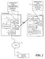
- FIG. 1is an illustration of a vending machine service request system constructed in accordance with one embodiment of the invention.
- FIG. 2is a more detailed block diagram of the system illustrated in FIG. 1 .
- FIG. 3is an exploded perspective view of a telephone housing a transceiver constructed in accordance with the invention as shown in FIG. 1 .
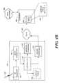
- FIG. 4Ais a block diagram illustrating a transceiver constructed in accordance with the present invention in communication with a central monitoring station.
- FIG. 4Bis a block diagram illustrating the transceiver of FIG. 4A in communication with a wide area computer network via a gateway computer.
- FIG. 5is a diagram illustrating the look-up table of FIGS. 4A and 4B showing relevant vending/service machine status.
- FIG. 6is a flowchart illustrating the top-level functional operation of a transceiver constructed in accordance with one embodiment of the present invention.
- FIG. 7is a flowchart illustrating the top-level functional operation of a system constructed in accordance with one embodiment of the present invention.
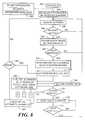
- FIG. 8is a flowchart illustrating the functional operation of a transceiver integrated within a pay phone host in accordance with one embodiment of the present invention.
- FIG. 9is a block diagram illustrating a vending machine service request system constructed in accordance with several embodiments of the invention.
- FIG. 10is a schematic diagram illustrating the interface between a transceiver and the IMDBIS.
- FIG. 1illustrates a typical operational environment of the present invention.
- the environment illustratedis one which provides operational status monitoring and automated servicing of a vending machine 120 .
- a vending machine 120such as a soda dispensing machine, includes an internal transmitter 148 or alternatively, an internal RF transceiver 140 , that communicates information via RF signal 130 to a nearby transceiver which may be located in pay-type telephone 110 .
- the transceivermay be incorporated into a variety of devices, so long as it has access to a phone line, preferably one forming a part of the PSTN 160 .
- the RF transceiver 140includes receiver circuitry for receiving the transmitted signal 130 and a transmitter for communicating data via the PSTN 160 to a central station 162 .
- the central station 162may be a central dispatch location, that is configured to dispatch service personnel to attend to the vending machine 120 .
- the vending machine 120may encompass a wide variety of devices, in addition to a soda dispensing machine.
- the vending machine 120may include a snack dispensing apparatus, a candy dispensing apparatus, a cigarette dispensing apparatus, a newspaper dispensing apparatus, an ice dispensing apparatus, among many other product or service dispensing devices.
- a variety of sensorsmay be integrated via sensor circuitry to RF transmitter 148 , or alternatively, RF transceiver 140 in vending machine 120 for detecting a variety of events. For example, detecting whether the machine 120 is low on a given product, or out of a product; determining whether the machine is out of change; determining if the machine has taken in a predetermined amount of money, which should be emptied; detecting if the machine is out of order; etc.
- These, and other events sensed within the vending machine 120may be communicated to the transmitter 148 , which then formats the data in a way that it may be readily understood by the transceiver integrated within telephone 110 .
- the transmitter 148transmits the data (preferably via RF link 130 ) to the transceiver disposed within the telephone 110 .
- This informationis communicated from the transceiver via PSTN 160 to the central station 162 . Based upon the information received, the central station 162 will institute an appropriate response.
- the information receivedis a notification that one or more of the products in the vending machine 120 is either low or out of stock
- a first personmay be dispatched to restock the machine.
- a second personservice person may be dispatched to service the machine.
- FIG. 2illustrates the circuitry within the vending machine 120 , as well as the circuitry within the telephone 110 , for carrying out the inventive aspects.
- various sensorsare disposed within the vending machine 120 . These include one or more product sensors configured to determine whether a given product is either low or out of stock. The sensors may also include operational sensors configured to detect machine malfunctions (e.g., out of order conditions) or other conditions relating to the operation of the vending machine 120 . Outputs of the various sensors are directed to sensor circuitry 142 , which provides an appropriate input signal to the controller 146 and the data formatter 144 which process the signal before forwarding the sensor information signal to the RF transmitter 149 .
- the output of the sensor circuitry 142is directed to a controller 146 , which may comprise dedicated circuitry, or may alternatively comprise general purpose programmable hardware, such as a microprocessor or microcontroller.
- the controller 146in essence, handles the processing of most of the functional operations carried out at the vending machine 120 .
- the transmitter 148or alternatively the RF transceiver 140 , of the preferred embodiment is characterized by an open-ended architecture that is configured to receive an encoded instruction.
- This encoded instructionmay be decoded to identify specific and unique functions and/or instructions. For example, one code may uniquely describe the event of the vending machine 120 running out of a certain product. Although this code may be meaningless to the RF transceiver 140 , when decoded by the central station 162 , an appropriate action may be taken.
- a first vending machine companymay utilize a given code to define a certain event relevant to the vending machine 120
- a second vending machine enterprisemay utilize the same code to define a completely different event.
- the same general purpose transceivermay be used to implement both embodiments.
- the controller 146is preferably configured to receive sensor outputs and compose the appropriate instruction code for transmission to the transceiver 128 located within telephone 110 .
- a data formatter 144may also be provided within the vending machine 120 . As the name implies, the data formatter 144 formats the data for transmission to the transceiver 128 . It will be appreciated that, in addition to the instruction code described above, it may also supply other information for transmission. As illustrated by the block 157 (exploded from the data formatter 144 ), information such as a transmitter identification code, and a destination phone number may also be included in the information transmitted to the transceiver 128 .
- the transmitter identification codeuniquely identifies the transmitter 148 , which code may be decoded at the central station 162 to identify the specific vending machine that created a received message. That is, the instruction code may inform the central station 162 as to the particular service need of the vending machine 120 , and the transmitter identification code may inform the central station 162 of the particular vending machine 120 , its location, and its need for service.
- the data formatter 144may also include the phone number of the central station 162 ; namely, the phone number that the transceiver 128 is to dial over the PSTN 160 .
- a generic (open-ended) transceiver 128may be utilized and installed in mass within public, pay-type telephones, by the service provider.
- various companiesmay then utilize specially configured transmitters 148 to communicate with the general purpose transceiver 128 to communicate a wide variety of information to central locations, defined by the transmitters 148 .
- telephone 110may be integrated with a transceiver 128 .
- the transceiver 128may comprise a RF receiver 150 , a data formatter 144 , a controller 146 , and a phone interface 154 .
- RF receiver 150may be configured to receive RF link 130 from a transmitter 148 , or alternatively a RF transceiver 140 disposed within vending machine 120 as previously described. RF receiver 150 may process the received information signal and forward a demodulated signal to data formatter 144 . Data formatter 144 formats the data for processing by controller 146 , which may forward the received instruction codes, transmitter identification, the central station phone number, and other information to phone interface 154 .
- Phone interface 154is configured to initialize a call via PSTN 160 to central station 162 . Once phone interface 154 verifies that a call has been initialized, a data transmission is forwarded to central station 162 .
- FIG. 3is an exploded perspective view of a telephone 110 incorporating a transceiver 128 constructed in accordance with the present invention.
- the transceiver 128may be provided in a single module having an associated battery pack 159 .
- the transceiver 128could be designed to operate from the power supplied to the telephone.
- the transceiver 128may be configured to snap into a space provided in the telephone.
- An external wire 153may be provided to act as an antenna for the transceiver 128 .
- a smaller internal antennamay be provided.
- the output from the transceiveris via cable 180 , which may terminate at an RJ11 connector, having Ring, Tip, and Common (RTC) conductors.
- FIG. 4Aillustrates (generically) a system constructed in accordance with the present invention.
- the drawingmore specifically illustrates an open-ended transceiver 270 constructed in accordance with the present invention.
- the transceiver 270includes a RF receiver circuit 150 that is configured to receive an electromagnetic signal (e.g., RF, optical, etc.).
- this signalincludes an instruction code, and possibly other items such as a phone number, a transmitter identification code, etc.
- a data formatter 144is provided in connection with a controller 146 to further format a signal that is to be output from the transceiver 270 to the central station 162 .
- additional informationmay be added to the signal that is transmitted to the central station 162 .
- a transceiver identification codemay be added to the signal.
- the central station 162may decode the transmitter identification code (if provided) to identify, for example, a geographic location of a transmitter, in environments where the transmitter is mobile (i.e., hand-held), a transmitter identification code may be of no use in identifying a geographic location. In such an environment, the addition of a transceiver code will facilitate the identification of the transmitter location (recognizing that the transmitter will be located in the proximity of the transceiver 270 ).
- the controller 146preferably performs the overall control and synchronization of functional operations within the transceiver 270 .
- the controller 146may be a general purpose microprocessor or micro-controller. If so, memory 257 may be provided to store programmable code for controlling the operation of the controller 146 .
- Phone interface 154may also be provided for interfacing to the PSTN 160 .
- Telephone 110typically has circuitry configured to interface with the local loop of the PSTN 160 .
- Phone interface 154 within the transceiver 270is designed to interface with this typical/standard telephone circuitry. The specific implementation of the circuitry within phone interface 154 will be appreciated by persons skilled in the art and need not be described in detail herein.
- a look-up table 266is also illustrated in FIG. 4 . It is illustrated in dashed line to represent that it may be optionally provided within the transceiver 270 . Consistent with the broader concepts of the invention, in certain embodiments, it may be desired to provide a more application specific transceiver 270 . In such embodiments, a look-up table 266 may be provided within the transceiver for decoding information such as the instruction code, the transmitter identification code, or any other information that may be transmitted from the transmitter. The specific use of such data will necessarily be application specific and controlled by the controller 146 , and need not be described herein.
- a computer 290may be provided to receive and process data received from the transceiver 270 via the PSTN 160 .
- a database 292including a second look-up table 294 , may be provided. Since the present invention is directed to the transceiver 270 , a variety of platforms may actually be implemented at the central station 162 . It will be appreciated, however, that with a computer implementation, an extremely flexible and robust operation may be achieved. For example, the response of the central station 162 to various incoming messages may be programmed to vary depending upon the contents of the message.
- the central station 162may employ the second look-up table 294 , like that illustrated in FIG. 5 .
- FIG. 4Billustrates another embodiment of the system introduced in FIG. 4 B.
- the drawingmore specifically illustrates that the central station 162 of FIG. 4A make take the form of a Gateway computer 282 further integrated with a wide area network (WAN) 284 .
- WANwide area network
- an open-ended transceiver 270 constructed in accordance with the present inventionmay be used to communicate an instruction code and other information such as a phone number, Internet protocol address, a transmitter identification code, etc. to a remote location.
- the remote locationmay be a gateway computer 282 configured to interface with a WAN 284 , such as the Internet.
- the gateway computer 282may be configured to forward the instruction code, a transmitter identification code and other information such as one or more transceiver identification codes, etc. to a computer identified via an Internet protocol address in the transmitter data transmission. In this way, an Internet addressed computer can receive and format various messages over a wide geographic area for monitoring and retrieval by anyone with access to the particular Internet computer.
- the combination of local gateway computers 282 with one or more computers integrated to the WAN 284provides a redundant and robust distributed network for managing and servicing vending and service machines. As previously described in relation to FIG. 4A, and applied to the configuration of FIG. 4B, the Gateway computer 282 may responsively alert dedicated persons that a particular vending or service machine in the reporting network is in need of technical service via any Internet connected reporting device.
- the Gateway computer 282may responsively alert an appropriate person that a particular vending machine that is out of or running low on a given product. Either the Gateway computer 292 or an Internet connected reporting device, upon recognizing this condition, may alert the appropriate person to restock the machine. In order to identify the contents of the various incoming messages, the gateway computer 282 may employ the second look-up table 294 , like that illustrated in FIG. 5 .
- a look-up table 294is illustrated.
- the look-up table 294may take on a wide variety of forms, the table illustrated in FIG. 5 includes two columns of data.
- the first columnis a listing of the various instruction codes that may be transmitted by the transmitter 148 to the transceiver 270 , and forwarded by the transceiver 270 to the central station 162 .
- the second columncontains the specific functions or instructions that correspond to the transmitted/received instruction code.
- the computer 290 at the central station 162can readily identify the function or instruction that is to be executed.
- one codemay indicate that a particular vending machine “n” is low on a specific product “X.” Another code may indicate that a particular vending machine's internal temperature is greater than a set threshold temperature. Yet another code may indicate that an industrial trash compactor “m” is in need of service.
- the instruction codesthemselves may be encoded to uniquely identify particular machines or persons. More particularly, in the illustrated embodiment, instruction code 00000001 identifies that vending machine “n” is low on product “X.” In yet another embodiment, this same code may indicate that a vending machine's 120 inventory is low on a particular product. Additional codes may be generated at the transmitter 148 and decoded at the central station 162 to provide this more specific information. For example, a transmitter identification code may be decoded by the central station 162 to identify the specific vending machine that is low on product. Likewise, an additional code, such as a product code, may be generated by the transmitter 148 to identify the specific product that is low. Thus, in such an alternative embodiment, multiple look-up tables 294 may be utilized at the central station 162 .
- FIG. 6is a flowchart that depicts the top-level functional operation of a transceiver 270 constructed in accordance with one embodiment of the invention.
- processing flowstarts with step 300 designated “start.”
- step 302the transceiver 270 awaits the receipt of a signal transmitted from a transmitter 148 .
- the transceiver 270(through the controller 146 and data formatter 144 ) looks to identify and/or isolate the instruction code in step 304 .
- the transceiver 270also looks, if appropriate, to identify a phone number of a central station in step 306 .
- the transceiver 270dials the corresponding central station in step 308 , establishing a connection over the PSTN 162 .
- the transceivermay be configured to seize the phone line. Thus, anyone making a call or any call currently in progress would be disconnected.
- the transceiver 270(through the controller 146 ) may be configured to test the phone line for its present availability. If a call is in progress, the controller 146 may store the message received from the transmitter 148 and await the availability of the phone line. Once the phone line becomes available, then the transceiver 270 may assume the line and place its call.
- the transceiver 270may be configured to implement simultaneous voice/data technology to place the phone call to the central station 162 without interrupting any ongoing call.
- a different servicemay be provided in connection with the telephone 110 through which to place the call.
- the telephone 110may also be equipped with an ISDN service or a DSL service, through which the data transmitted is communicated. As is known, communication through such a service may be made without interruption to a call ongoing in the POTS frequency band.
- the transceiver 270transmits the message, including the instruction code, and, if relevant, the transmitter identification code, the destination phone number, the transceiver identification code, etc. in step 310 .
- FIG. 7a flowchart is shown that illustrates the top-level functional operation of a system, in accordance with one aspect of the invention.
- the systemremains in an idle state, until the transmitter 148 becomes activated in step 320 . This may be accomplished by a periodic check for a trigger condition as illustrated in step 322 .
- the transmitter 148transmits a signal in step 324 , including at least an instruction code in step 326 . Thereafter, the transceiver 148 operates in accordance with the flowchart of FIG. 6 .
- the central station 162then decodes information received via the PSTN 160 (specifically, decoding the instruction code).
- the central station 162Based upon the decoded instruction code (and perhaps other codes in some embodiments), the central station 162 initiates an appropriate action in response as shown in step 330 . For example, in response to a distress call, the central station 162 may dispatch product supply personnel as shown in step 332 . In response to a service request, the central station 162 may dispatch service personnel as shown in step 334 . In response to other types of messages or requests, the central station 162 may dispatch other personnel or take other appropriate action as shown in step 336 .
- FIG. 8is a flowchart that depicts the operation of the system from more of a hardware level, as opposed to a functional level.
- FIG. 8is a flowchart illustrating the functional operation of a transceiver integrated within a pay phone host in accordance with one embodiment of the present invention. The flowchart of FIG. 8 will not be described herein in detail, as a person of ordinary skill in the art will appreciate the system operation simply from a review of the flowchart and the nomenclature provided therein.
- Transceiver operationbegins in step 342 designated, “power up.” Having received a triggering signal as indicated in step 343 , the transceiver responds by initializing each of its functional components as illustrated in step 344 . Having initialized its functional components, the transceiver reads data from its RF input/output port in step 348 . Next, in step 348 , the transceiver checks if the RF port is active. If no, the transceiver returns processing to step 346 where it reads the RF input output port. If yes, data read from the RF port is forwarded to the CPU/decoder functions in step 350 .
- step 352the transceiver performs a validity check on the message format of the data received and processed in the preceding steps. If the message does not meet the parameters of a valid message, the transceiver returns processing to step 346 . If the message is valid, the transceiver transfers the transmitter data, identification code, and miscellaneous data received to the modem buffer in step 354 .
- the transceiveractivates a modem dial out in step 356 .
- the modem dial outis accomplished by manipulating the ring, tip, and common circuits as illustrated in step 358 in order to seize the phone line.
- the transceivernext performs a check in step 362 to determine if the modem is properly connected to the central station 162 via the PSTN 160 . If the determination in step 362 is no, the transceiver continues by adjusting a redial counter in step 364 and determining whether the modem should redial the central station in step 366 . If the determination to redial is affirmative, the transceiver returns processing to step 356 (activate modem dial out).
- step 362If the determination in step 362 was that a valid modem call was established, the transceiver continues processing by forwarding the formatted data stream via the modem in step 368 . Having activated the data transfer, the transceiver periodically performs a check in step 370 to determine if the data transmission is complete. If the data transmission is not complete, processing returns to step 368 . If it is determined in step 370 that the data transmission has completed, the transceiver returns processing to step 346 where the transceiver reads the RF input/output ports.
- FIG. 9illustrates the top-level functional operation of a system, in accordance with one aspect of the invention.
- the systemintegrates a multiplicity of transceivers 140 , 947 , and 948 integrated with vending/service machines 115 , 120 , and 925 to communicate via multiple RF links 930 , 931 , 932 , 933 , and 934 with the PSTN 160 and ultimately the central station 162 .
- the IMD busis well known and specified by standards, it need not be described herein. For at least the same reason, persons skilled in the art will understand how to implement an IMD bus interface 943 . Therefore, such an interface need not be described herein.
- Vending/service machine 120is configured with an IMD bus interface 943 to enable the processing of machine status information via controller 146 and data formatter 144 for transmission by RF transceiver 150 via RF links 931 and 932 to devices configured to access the PSTN 160 .
- Vending/service machine 925is configured with a cellular transmitter 945 to enable access to PSTN 160 via local cellular network 970 via RF link 933 .
- vending/service machine 925can relay status information from proximally located vending/service machines 115 and 120 via transceiver 150 and RF link 934 to a proximally located pay phone 110 configured with a transceiver (see FIG. 3 ).
- FIG. 10is a schematic diagram illustrating the details of the electrical interface necessitated by the IMD bus interface. It will be appreciated by those skilled in the art that the Multi-Function General Purpose Transceiver can be readily configured to tap into the IMD bus and thus can enable the transfer of product supply, machine status, cash validation, card reading, and peripheral communications with one or more remote locations.
- the message transmitted by the multiple transceiversmay be as simple as an instruction code that defines a condition of the vending machines 115 , 120 , and 925 , that a central station 162 may decode and act upon.
- each of the multiple transceivers 115 , 120 , and 925may be specifically configured to establish a phone connection with a predetermined central station 162 .
- a RF transmittermay encode a message that transmits both an instruction code and a phone number used to establish communications between the RF transmitter and a central station.
- a generic transceiverallows a generic transceiver to be utilized, such that multiple enterprises may utilize this common, generic transceiver for various applications. Consistent with these broad concepts, a variety of other configurations may be employed as well.
Landscapes
- Physics & Mathematics (AREA)
- General Physics & Mathematics (AREA)
- Business, Economics & Management (AREA)
- Accounting & Taxation (AREA)
- Engineering & Computer Science (AREA)
- Strategic Management (AREA)
- General Business, Economics & Management (AREA)
- Theoretical Computer Science (AREA)
- Computer Security & Cryptography (AREA)
- Control Of Vending Devices And Auxiliary Devices For Vending Devices (AREA)
Abstract
Description
Claims (24)
Priority Applications (1)
| Application Number | Priority Date | Filing Date | Title |
|---|---|---|---|
| US09/558,030US6628764B1 (en) | 1997-02-14 | 2000-04-25 | System for requesting service of a vending machine |
Applications Claiming Priority (9)
| Application Number | Priority Date | Filing Date | Title |
|---|---|---|---|
| US4031697P | 1997-02-14 | 1997-02-14 | |
| US08/825,576US7137550B1 (en) | 1997-02-14 | 1997-03-31 | Transmitter for accessing automated financial transaction machines |
| US08/895,720US5926531A (en) | 1997-02-14 | 1997-07-17 | Transmitter for accessing pay-type telephones |
| US91098097A | 1997-08-07 | 1997-08-07 | |
| US5964397P | 1997-09-20 | 1997-09-20 | |
| US09/102,178US6430268B1 (en) | 1997-09-20 | 1998-06-22 | Systems for requesting service of a vending machine |
| US09/102,399US6233327B1 (en) | 1997-02-14 | 1998-06-22 | Multi-function general purpose transceiver |
| US14158599P | 1999-06-29 | 1999-06-29 | |
| US09/558,030US6628764B1 (en) | 1997-02-14 | 2000-04-25 | System for requesting service of a vending machine |
Related Parent Applications (1)
| Application Number | Title | Priority Date | Filing Date |
|---|---|---|---|
| US09/102,399Continuation-In-PartUS6233327B1 (en) | 1997-02-14 | 1998-06-22 | Multi-function general purpose transceiver |
Publications (1)
| Publication Number | Publication Date |
|---|---|
| US6628764B1true US6628764B1 (en) | 2003-09-30 |
Family
ID=28795453
Family Applications (1)
| Application Number | Title | Priority Date | Filing Date |
|---|---|---|---|
| US09/558,030Expired - LifetimeUS6628764B1 (en) | 1997-02-14 | 2000-04-25 | System for requesting service of a vending machine |
Country Status (1)
| Country | Link |
|---|---|
| US (1) | US6628764B1 (en) |
Cited By (144)
| Publication number | Priority date | Publication date | Assignee | Title |
|---|---|---|---|---|
| US20020114433A1 (en)* | 2001-02-20 | 2002-08-22 | Honda Giken Kogyo Kabushiki Kaisha | Machine remote monitoring system and management method |
| US20020130552A1 (en)* | 2000-07-28 | 2002-09-19 | Juncker David L. | Drive wheel for track apparatus |
| US20040229578A1 (en)* | 2003-05-12 | 2004-11-18 | Power Measurement Ltd. | Wireless communications system incorporating intelligent electronic devices |
| US20050065743A1 (en)* | 2003-03-31 | 2005-03-24 | Cumming Daniel A. | Methods and apparatus for retrieving energy readings from an energy monitoring device |
| US20050108523A1 (en)* | 2003-02-22 | 2005-05-19 | Earle West | Method and apparatus for collecting remote data |
| US20050123657A1 (en)* | 2003-12-04 | 2005-06-09 | Beckman Mark J. | Process for assembly and installation of a snack package adapted for attachment to a beverage container thereby allowing the combination to take up the same shelf space as the container alone for vending and off-the-shelf sales with augmented marketing adaptation |
| US20050151660A1 (en)* | 2004-01-06 | 2005-07-14 | Mou David W.H. | System, method, and apparatus for remotely monitoring the status of a machine |
| US20050167440A1 (en)* | 2003-07-14 | 2005-08-04 | Doug Huffer | Can and bottle dispenser |
| US6990392B1 (en)* | 2000-08-23 | 2006-01-24 | Spencer Andrew Meister | Apparatus and method for providing items of value in cooperation with operation of a companion device |
| US20060044110A1 (en)* | 2004-08-31 | 2006-03-02 | Napolitano Thomas J | System and method for detecting access to an article or opening of a package |
| WO2005057375A3 (en)* | 2003-12-09 | 2006-04-13 | Walker Digital Llc | Marketing system employing vending machines |
| US20060149415A1 (en)* | 2004-12-10 | 2006-07-06 | Coinstar, Inc. | Systems and methods for collecting vend data from, and exchanging information with, vending machines and other devices |
| US7079810B2 (en) | 1997-02-14 | 2006-07-18 | Statsignal Ipc, Llc | System and method for communicating with a remote communication unit via the public switched telephone network (PSTN) |
| US20060165044A1 (en)* | 2004-12-03 | 2006-07-27 | Advanced Metering Data Systems, L.L.C. | Method, system, apparatus, and computer program product for communications relay |
| US7089322B1 (en)* | 1999-10-28 | 2006-08-08 | Motient Communications Inc. | System and method of aggregating data from a plurality of data generating machines |
| US7103511B2 (en) | 1998-10-14 | 2006-09-05 | Statsignal Ipc, Llc | Wireless communication networks for providing remote monitoring of devices |
| US20060219517A1 (en)* | 2005-03-31 | 2006-10-05 | Cantaloupe Systems, Inc. (In Counterpart) | Remote management of vending machines |
| US7137550B1 (en) | 1997-02-14 | 2006-11-21 | Statsignal Ipc, Llc | Transmitter for accessing automated financial transaction machines |
| US20060265101A1 (en)* | 2005-04-22 | 2006-11-23 | Gregg Kaplan | System and method for communicating vending information |
| US20060293956A1 (en)* | 2003-12-09 | 2006-12-28 | Walker Jay S | Systems and methods for e-mail marketing via vending machines |
| US20070033068A1 (en)* | 2005-08-08 | 2007-02-08 | Rajendra Rao | Physical rehabilitation systems and methods |
| US7234609B2 (en) | 2004-04-15 | 2007-06-26 | Redbox Automated Retail, L.L.C. | Article dispensing system and method for same |
| US20070156253A1 (en)* | 2006-01-03 | 2007-07-05 | Industrial Telemetry, Inc. | Apparatus and method for wireless process control |
| US7263073B2 (en) | 1999-03-18 | 2007-08-28 | Statsignal Ipc, Llc | Systems and methods for enabling a mobile user to notify an automated monitoring system of an emergency situation |
| US7295128B2 (en) | 1998-06-22 | 2007-11-13 | Sipco, Llc | Smoke detection methods, devices, and systems |
| US20080068215A1 (en)* | 2006-09-15 | 2008-03-20 | Stuber Michael T G | Home area networking (HAN) with low power considerations for battery devices |
| US20080069013A1 (en)* | 2006-09-15 | 2008-03-20 | Fabrice Monier | Beacon requests and RS bit resolving circular routes |
| US20080074285A1 (en)* | 2006-08-31 | 2008-03-27 | Guthrie Kevin D | Interface between meter and application (IMA) |
| US7397907B2 (en) | 1997-02-14 | 2008-07-08 | Sipco, Llc | Multi-function general purpose transceiver |
| US7424527B2 (en) | 2001-10-30 | 2008-09-09 | Sipco, Llc | System and method for transmitting pollution information over an integrated wireless network |
| US7447605B2 (en) | 2004-04-15 | 2008-11-04 | Redbox Automated Retail, Llc | System and method for calibrating a vending apparatus |
| US20080273486A1 (en)* | 2007-04-13 | 2008-11-06 | Hart Communication Foundation | Wireless Protocol Adapter |
| US20080279155A1 (en)* | 2007-04-13 | 2008-11-13 | Hart Communication Foundation | Adaptive Scheduling in a Wireless Network |
| US20090010205A1 (en)* | 2007-04-13 | 2009-01-08 | Hart Communication Foundation | Priority-Based Scheduling and Routing in a Wireless Network |
| US20090010203A1 (en)* | 2007-04-13 | 2009-01-08 | Hart Communication Foundation | Efficient Addressing in Wireless Hart Protocol |
| US7480501B2 (en) | 2001-10-24 | 2009-01-20 | Statsignal Ipc, Llc | System and method for transmitting an emergency message over an integrated wireless network |
| US20090046675A1 (en)* | 2007-04-13 | 2009-02-19 | Hart Communication Foundation | Scheduling Communication Frames in a Wireless Network |
| US20090059814A1 (en)* | 2007-08-31 | 2009-03-05 | Fisher-Rosemount Sytems, Inc. | Configuring and Optimizing a Wireless Mesh Network |
| US7584869B2 (en) | 2004-04-15 | 2009-09-08 | Redbox Automated Retail, Llc | Article dispensing system and method for same |
| US20090287838A1 (en)* | 2002-11-18 | 2009-11-19 | Seyamak Keyghobad | Method and apparatus for inexpensively monitoring and controlling remotely distributed appliances |
| EP2138983A2 (en) | 2008-06-26 | 2009-12-30 | Steven Michael Faes | Article storage and retrieval apparatus and vending machine |
| US7650425B2 (en) | 1999-03-18 | 2010-01-19 | Sipco, Llc | System and method for controlling communication between a host computer and communication devices associated with remote devices in an automated monitoring system |
| US7673555B2 (en) | 2005-04-11 | 2010-03-09 | Starbucks Corporation | Machine for brewing a beverage such as coffee and related method |
| US7697492B2 (en) | 1998-06-22 | 2010-04-13 | Sipco, Llc | Systems and methods for monitoring and controlling remote devices |
| US7719432B1 (en) | 2005-02-04 | 2010-05-18 | The Toro Company | Long range, battery powered, wireless environmental sensor interface devices |
| US20100152893A1 (en)* | 2008-12-11 | 2010-06-17 | Christopher Percing Fure | Method and apparatus for on-demand kiosk fulfillment with origination, billing, and management via telecommunications network |
| US7756086B2 (en) | 2004-03-03 | 2010-07-13 | Sipco, Llc | Method for communicating in dual-modes |
| US7778600B2 (en)* | 2001-06-29 | 2010-08-17 | Crane Merchandising Systems, Inc. | Apparatus and method to provide multiple wireless communication paths to and from remotely located equipment |
| US7843391B2 (en) | 2006-09-15 | 2010-11-30 | Itron, Inc. | RF local area network antenna design |
| US7847536B2 (en) | 2006-08-31 | 2010-12-07 | Itron, Inc. | Hall sensor with temperature drift control |
| US8000314B2 (en) | 1996-12-06 | 2011-08-16 | Ipco, Llc | Wireless network system and method for providing same |
| US8005425B2 (en) | 2001-06-29 | 2011-08-23 | Crane Merchandising Systems, Inc. | Method and system for interfacing a machine controller and a wireless network |
| US8013732B2 (en) | 1998-06-22 | 2011-09-06 | Sipco, Llc | Systems and methods for monitoring and controlling remote devices |
| US8024724B2 (en) | 2006-08-31 | 2011-09-20 | Itron, Inc. | Firmware download |
| US8031650B2 (en) | 2004-03-03 | 2011-10-04 | Sipco, Llc | System and method for monitoring remote devices with a dual-mode wireless communication protocol |
| US8049642B2 (en) | 2006-09-05 | 2011-11-01 | Itron, Inc. | Load side voltage sensing for AMI metrology |
| US8055461B2 (en) | 2006-09-15 | 2011-11-08 | Itron, Inc. | Distributing metering responses for load balancing an AMR network |
| US8060247B2 (en) | 2005-04-22 | 2011-11-15 | Redbox Automated Retail, Llc | System and method for communicating secondary vending options |
| US8064412B2 (en) | 1998-06-22 | 2011-11-22 | Sipco, Llc | Systems and methods for monitoring conditions |
| US8138944B2 (en) | 2006-09-15 | 2012-03-20 | Itron, Inc. | Home area networking (HAN) with handheld for diagnostics |
| US8138934B2 (en) | 2007-11-25 | 2012-03-20 | Trilliant Networks, Inc. | System and method for false alert filtering of event messages within a network |
| US8144596B2 (en) | 2007-11-25 | 2012-03-27 | Trilliant Networks, Inc. | Communication and message route optimization and messaging in a mesh network |
| US8171364B2 (en) | 2007-11-25 | 2012-05-01 | Trilliant Networks, Inc. | System and method for power outage and restoration notification in an advanced metering infrastructure network |
| US8212687B2 (en) | 2006-09-15 | 2012-07-03 | Itron, Inc. | Load side voltage sensing for AMI metrology |
| US8289182B2 (en) | 2008-11-21 | 2012-10-16 | Trilliant Networks, Inc. | Methods and systems for virtual energy management display |
| US8312103B2 (en) | 2006-08-31 | 2012-11-13 | Itron, Inc. | Periodic balanced communication node and server assignment |
| US8319658B2 (en) | 2009-03-11 | 2012-11-27 | Trilliant Networks, Inc. | Process, device and system for mapping transformers to meters and locating non-technical line losses |
| US20120310570A1 (en)* | 2011-06-03 | 2012-12-06 | Pyne John W | Systems and Methods for Determining Stock Quantities Using a Capacitive Inventory Sensor |
| US8332055B2 (en) | 2007-11-25 | 2012-12-11 | Trilliant Networks, Inc. | Energy use control system and method |
| US8334787B2 (en) | 2007-10-25 | 2012-12-18 | Trilliant Networks, Inc. | Gas meter having ultra-sensitive magnetic material retrofitted onto meter dial and method for performing meter retrofit |
| US8371211B2 (en) | 2005-04-11 | 2013-02-12 | Starbucks Corporation | Machine for brewing a beverage such as coffee and related method |
| US8384558B2 (en) | 2006-10-19 | 2013-02-26 | Itron, Inc. | Extending contact life in remote disconnect applications |
| US8410931B2 (en) | 1998-06-22 | 2013-04-02 | Sipco, Llc | Mobile inventory unit monitoring systems and methods |
| US8441947B2 (en) | 2008-06-23 | 2013-05-14 | Hart Communication Foundation | Simultaneous data packet processing |
| US8489063B2 (en) | 2001-10-24 | 2013-07-16 | Sipco, Llc | Systems and methods for providing emergency messages to a mobile device |
| US8538581B2 (en) | 2010-09-03 | 2013-09-17 | Redbox Automated Retail, Llc | Article vending machine and method for authenticating received articles |
| US8587452B2 (en) | 2003-05-12 | 2013-11-19 | Power Measurement Ltd. | Time coordinated energy monitoring system utilizing communications links |
| US8649907B2 (en) | 2008-08-12 | 2014-02-11 | Rain Bird Corporation | Method and system for irrigation control |
| US8660134B2 (en) | 2011-10-27 | 2014-02-25 | Mueller International, Llc | Systems and methods for time-based hailing of radio frequency devices |
| US8690117B2 (en) | 2006-05-04 | 2014-04-08 | Capstone Metering Llc | Water meter |
| US8699377B2 (en) | 2008-09-04 | 2014-04-15 | Trilliant Networks, Inc. | System and method for implementing mesh network communications using a mesh network protocol |
| US8712872B2 (en) | 2012-03-07 | 2014-04-29 | Redbox Automated Retail, Llc | System and method for optimizing utilization of inventory space for dispensable articles |
| US8768789B2 (en) | 2012-03-07 | 2014-07-01 | Redbox Automated Retail, Llc | System and method for optimizing utilization of inventory space for dispensable articles |
| US8787246B2 (en) | 2009-02-03 | 2014-07-22 | Ipco, Llc | Systems and methods for facilitating wireless network communication, satellite-based wireless network systems, and aircraft-based wireless network systems, and related methods |
| US8787210B2 (en) | 2006-09-15 | 2014-07-22 | Itron, Inc. | Firmware download with adaptive lost packet recovery |
| US8823509B2 (en) | 2009-05-22 | 2014-09-02 | Mueller International, Llc | Infrastructure monitoring devices, systems, and methods |
| US8832428B2 (en) | 2010-11-15 | 2014-09-09 | Trilliant Holdings Inc. | System and method for securely communicating across multiple networks using a single radio |
| US8833390B2 (en) | 2011-05-31 | 2014-09-16 | Mueller International, Llc | Valve meter assembly and method |
| US8855569B2 (en) | 2011-10-27 | 2014-10-07 | Mueller International, Llc | Systems and methods for dynamic squelching in radio frequency devices |
| US8856323B2 (en) | 2011-02-10 | 2014-10-07 | Trilliant Holdings, Inc. | Device and method for facilitating secure communications over a cellular network |
| US8866634B2 (en) | 2006-05-04 | 2014-10-21 | Capstone Metering Llc | System and method for remotely monitoring and controlling a water meter |
| US8892769B2 (en) | 2007-04-13 | 2014-11-18 | Hart Communication Foundation | Routing packets on a network using directed graphs |
| US8931505B2 (en) | 2010-06-16 | 2015-01-13 | Gregory E. HYLAND | Infrastructure monitoring devices, systems, and methods |
| US8964338B2 (en) | 2012-01-11 | 2015-02-24 | Emerson Climate Technologies, Inc. | System and method for compressor motor protection |
| US8970394B2 (en) | 2011-01-25 | 2015-03-03 | Trilliant Holdings Inc. | Aggregated real-time power outages/restoration reporting (RTPOR) in a secure mesh network |
| US8974573B2 (en) | 2004-08-11 | 2015-03-10 | Emerson Climate Technologies, Inc. | Method and apparatus for monitoring a refrigeration-cycle system |
| US8996162B2 (en) | 2009-09-05 | 2015-03-31 | Redbox Automated Retail, Llc | Article vending machine and method for exchanging an inoperable article for an operable article |
| US9001787B1 (en) | 2011-09-20 | 2015-04-07 | Trilliant Networks Inc. | System and method for implementing handover of a hybrid communications module |
| US9013173B2 (en) | 2010-09-13 | 2015-04-21 | Trilliant Networks, Inc. | Process for detecting energy theft |
| US9041349B2 (en) | 2011-03-08 | 2015-05-26 | Trilliant Networks, Inc. | System and method for managing load distribution across a power grid |
| US9084120B2 (en) | 2010-08-27 | 2015-07-14 | Trilliant Networks Inc. | System and method for interference free operation of co-located transceivers |
| US9104990B2 (en) | 2009-09-05 | 2015-08-11 | Redbox Automated Retail, Llc | Article vending machine and method for exchanging an inoperable article for an operable article |
| US9121407B2 (en) | 2004-04-27 | 2015-09-01 | Emerson Climate Technologies, Inc. | Compressor diagnostic and protection system and method |
| US9140728B2 (en) | 2007-11-02 | 2015-09-22 | Emerson Climate Technologies, Inc. | Compressor sensor module |
| US9202362B2 (en) | 2008-10-27 | 2015-12-01 | Mueller International, Llc | Infrastructure monitoring system and method |
| US9282383B2 (en) | 2011-01-14 | 2016-03-08 | Trilliant Incorporated | Process, device and system for volt/VAR optimization |
| US9285802B2 (en) | 2011-02-28 | 2016-03-15 | Emerson Electric Co. | Residential solutions HVAC monitoring and diagnosis |
| US9286617B2 (en) | 2011-08-12 | 2016-03-15 | Redbox Automated Retail, Llc | System and method for applying parental control limits from content providers to media content |
| US9310439B2 (en) | 2012-09-25 | 2016-04-12 | Emerson Climate Technologies, Inc. | Compressor having a control and diagnostic module |
| US9310094B2 (en) | 2007-07-30 | 2016-04-12 | Emerson Climate Technologies, Inc. | Portable method and apparatus for monitoring refrigerant-cycle systems |
| US9348822B2 (en) | 2011-08-02 | 2016-05-24 | Redbox Automated Retail, Llc | System and method for generating notifications related to new media |
| US9419888B2 (en) | 2011-12-22 | 2016-08-16 | Itron, Inc. | Cell router failure detection in a mesh network |
| US9439126B2 (en) | 2005-01-25 | 2016-09-06 | Sipco, Llc | Wireless network protocol system and methods |
| US9494249B2 (en) | 2014-05-09 | 2016-11-15 | Mueller International, Llc | Mechanical stop for actuator and orifice |
| US9495465B2 (en) | 2011-07-20 | 2016-11-15 | Redbox Automated Retail, Llc | System and method for providing the identification of geographically closest article dispensing machines |
| US9551504B2 (en) | 2013-03-15 | 2017-01-24 | Emerson Electric Co. | HVAC system remote monitoring and diagnosis |
| US9565620B2 (en) | 2014-09-02 | 2017-02-07 | Mueller International, Llc | Dynamic routing in a mesh network |
| US9569911B2 (en) | 2010-08-23 | 2017-02-14 | Redbox Automated Retail, Llc | Secondary media return system and method |
| US9638436B2 (en) | 2013-03-15 | 2017-05-02 | Emerson Electric Co. | HVAC system remote monitoring and diagnosis |
| US9703275B2 (en) | 2011-06-23 | 2017-07-11 | Rain Bird Corporation | Methods and systems for irrigation and climate control |
| US9747253B2 (en) | 2012-06-05 | 2017-08-29 | Redbox Automated Retail, Llc | System and method for simultaneous article retrieval and transaction validation |
| US9765979B2 (en) | 2013-04-05 | 2017-09-19 | Emerson Climate Technologies, Inc. | Heat-pump system with refrigerant charge diagnostics |
| US9785996B2 (en) | 2011-06-14 | 2017-10-10 | Redbox Automated Retail, Llc | System and method for substituting a media article with alternative media |
| US9803902B2 (en) | 2013-03-15 | 2017-10-31 | Emerson Climate Technologies, Inc. | System for refrigerant charge verification using two condenser coil temperatures |
| US9823632B2 (en) | 2006-09-07 | 2017-11-21 | Emerson Climate Technologies, Inc. | Compressor data module |
| US9829869B2 (en) | 2011-06-23 | 2017-11-28 | Rain Bird Corporation | Methods and systems for irrigation and climate control |
| EP3252722A1 (en)* | 2016-05-31 | 2017-12-06 | Accenture Global Solutions Limited | Data platform for a network connected dispensing device |
| US9842454B2 (en)* | 2016-03-31 | 2017-12-12 | International Business Machines Corporation | Analytics based climate control in vending machines |
| US9885507B2 (en) | 2006-07-19 | 2018-02-06 | Emerson Climate Technologies, Inc. | Protection and diagnostic module for a refrigeration system |
| US10019865B2 (en) | 2016-05-31 | 2018-07-10 | Accenture Global Solutions Limited | Control of a network connected dispensing device via a network |
| US10085393B2 (en) | 2005-02-04 | 2018-10-02 | The Toro Company | Long range, battery powered, wireless environmental sensor interface devices |
| US10134218B2 (en) | 2016-05-31 | 2018-11-20 | Accenture Global Solutions Limited | Network connected dispensing device |
| US10180414B2 (en) | 2013-03-15 | 2019-01-15 | Mueller International, Llc | Systems for measuring properties of water in a water distribution system |
| US10200476B2 (en) | 2011-10-18 | 2019-02-05 | Itron, Inc. | Traffic management and remote configuration in a gateway-based network |
| US10628186B2 (en)* | 2014-09-08 | 2020-04-21 | Wirepath Home Systems, Llc | Method for electronic device virtualization and management |
| US10716269B2 (en) | 2008-08-12 | 2020-07-21 | Rain Bird Corporation | Methods and systems for irrigation control |
| US10810822B2 (en) | 2007-09-28 | 2020-10-20 | Redbox Automated Retail, Llc | Article dispensing machine and method for auditing inventory while article dispensing machine remains operable |
| CN111811849A (en)* | 2020-06-23 | 2020-10-23 | 上海人云科技有限公司 | Intelligent container diagnosis system and diagnosis method |
| US10833799B2 (en) | 2018-05-31 | 2020-11-10 | Itron Global Sarl | Message correction and dynamic correction adjustment for communication systems |
| US10980120B2 (en) | 2017-06-15 | 2021-04-13 | Rain Bird Corporation | Compact printed circuit board |
| US11041839B2 (en) | 2015-06-05 | 2021-06-22 | Mueller International, Llc | Distribution system monitoring |
| US11418969B2 (en) | 2021-01-15 | 2022-08-16 | Fisher-Rosemount Systems, Inc. | Suggestive device connectivity planning |
| US11503782B2 (en) | 2018-04-11 | 2022-11-22 | Rain Bird Corporation | Smart drip irrigation emitter |
| US11725366B2 (en) | 2020-07-16 | 2023-08-15 | Mueller International, Llc | Remote-operated flushing system |
Citations (43)
| Publication number | Priority date | Publication date | Assignee | Title |
|---|---|---|---|---|
| US3906460A (en) | 1973-01-11 | 1975-09-16 | Halpern John Wolfgang | Proximity data transfer system with tamper proof portable data token |
| US4605844A (en) | 1985-02-11 | 1986-08-12 | At&T Technologies, Inc. | Computerized transaction card with inductive data transfer |
| US4757185A (en) | 1986-04-28 | 1988-07-12 | Hitachi, Ltd. | Automatic cash transaction apparatus |
| US4800543A (en) | 1987-12-03 | 1989-01-24 | Ramtron Corporation | Timepiece communication system |
| US4851654A (en) | 1987-05-30 | 1989-07-25 | Kabushiki Kaisha Toshiba | IC card |
| US4897644A (en) | 1983-09-19 | 1990-01-30 | Nissan Motor Company, Limited | Radio-wave transmission system of keyless entry system for automotive vehicle devices |
| US4906828A (en) | 1983-02-28 | 1990-03-06 | Paperless Accounting, Inc. | Electronic money purse and fund transfer system |
| US4991008A (en) | 1988-12-01 | 1991-02-05 | Intec Video Systems, Inc. | Automatic transaction surveillance system |
| US5111199A (en) | 1985-08-12 | 1992-05-05 | Nissan Motor Company, Limited | Pocket-portable radio code signal transmitter for automotive keyless entry system |
| US5113184A (en) | 1987-09-22 | 1992-05-12 | Hitachi Maxell, Ltd. | Method and system of communication for a non-contact ic card |
| US5113183A (en) | 1987-06-16 | 1992-05-12 | Casio Computer Co., Ltd. | Remote code transmission system between a nameplate apparatus and a data processing apparatus |
| US5130519A (en) | 1990-01-16 | 1992-07-14 | George Bush | Portable pin card |
| US5191192A (en) | 1990-09-10 | 1993-03-02 | Mitsubishi Denki Kabushiki Kaisha | Non-contact type information card and communication system |
| US5216502A (en) | 1990-12-18 | 1993-06-01 | Barry Katz | Surveillance systems for automatically recording transactions |
| US5235630A (en) | 1991-04-17 | 1993-08-10 | Telident, Incorporated | Emergency call station identification system and method |
| US5253167A (en) | 1989-06-15 | 1993-10-12 | Hitachi, Ltd. | Remote maintenance/supervisory system and method for automated teller machines |
| US5265162A (en) | 1990-01-16 | 1993-11-23 | George Bush | Portable pin card |
| US5305370A (en) | 1991-09-04 | 1994-04-19 | Lloyd Kearns | Personal emergency response communications system |
| US5317309A (en) | 1990-11-06 | 1994-05-31 | Westinghouse Electric Corp. | Dual mode electronic identification system |
| US5319364A (en) | 1988-05-27 | 1994-06-07 | Lectron Products, Inc. | Passive keyless entry system |
| US5319711A (en) | 1992-08-19 | 1994-06-07 | Gte Laboratories Incorporated | Wireless device for verifying identification |
| US5345231A (en) | 1990-08-23 | 1994-09-06 | Mikron Gesellschaft Fur Integrierte Mikroelectronik Mbh | Contactless inductive data-transmission system |
| US5347263A (en) | 1993-02-05 | 1994-09-13 | Gnuco Technology Corporation | Electronic identifier apparatus and method utilizing a single chip microcontroller and an antenna coil |
| US5354974A (en) | 1992-11-24 | 1994-10-11 | Base 10 Systems, Inc. | Automatic teller system and method of operating same |
| US5382778A (en) | 1991-11-26 | 1995-01-17 | Mitsubishi Denki Kabushiki Kaisha | Non-contact IC card |
| US5452344A (en)* | 1992-05-29 | 1995-09-19 | Datran Systems Corporation | Communication over power lines |
| US5467082A (en) | 1989-10-25 | 1995-11-14 | Sanderson; Glenn A. | Proximity actuator and reader for an electronic access system |
| US5484997A (en) | 1993-12-07 | 1996-01-16 | Haynes; George W. | Identification card with RF downlink capability |
| US5517188A (en) | 1994-02-24 | 1996-05-14 | Carroll; Gary T. | Programmable identification apparatus and method therefor |
| US5544784A (en)* | 1995-05-26 | 1996-08-13 | Motorola, Inc. | Rechargeable battery vending machine |
| US5548632A (en) | 1993-11-30 | 1996-08-20 | Lawrence Steelman | Safe alert emergency alerting system for remotely located sites |
| US5550535A (en) | 1992-08-14 | 1996-08-27 | Seiko Communications Holding N.V. | Bank balance notification by wristwatch pager |
| US5550359A (en) | 1994-09-14 | 1996-08-27 | Mikohn Gaming Corporation | Time and attendance system and method therefor |
| US5565857A (en) | 1991-10-31 | 1996-10-15 | Lee; Kwang-Sil | Electronic indentification system having remote automatic response capability and automatic identification method thereof |
| US5963452A (en)* | 1996-09-20 | 1999-10-05 | Kabushiki Kaisha Media Marketing Network | System for managing sales of goods for vending machines |
| US6032197A (en)* | 1997-09-25 | 2000-02-29 | Microsoft Corporation | Data packet header compression for unidirectional transmission |
| US6038491A (en)* | 1997-11-26 | 2000-03-14 | Mars, Incorporated | Monitoring and reporting system using cellular carriers |
| US6181981B1 (en)* | 1996-05-15 | 2001-01-30 | Marconi Communications Limited | Apparatus and method for improved vending machine inventory maintenance |
| US6233327B1 (en)* | 1997-02-14 | 2001-05-15 | Statsignal Systems, Inc. | Multi-function general purpose transceiver |
| US6314169B1 (en)* | 1997-02-06 | 2001-11-06 | Poweroasis, Inc. | Power and telecommunications access vending machine |
| US6430268B1 (en)* | 1997-09-20 | 2002-08-06 | Statsignal Systems, Inc. | Systems for requesting service of a vending machine |
| US6457038B1 (en)* | 1998-03-19 | 2002-09-24 | Isochron Data Corporation | Wide area network operation's center that sends and receives data from vending machines |
| US6462644B1 (en)* | 1998-11-19 | 2002-10-08 | The Coca-Cola Company | Network of vending machines connected interactively to data-base building host |
- 2000
- 2000-04-25USUS09/558,030patent/US6628764B1/ennot_activeExpired - Lifetime
Patent Citations (43)
| Publication number | Priority date | Publication date | Assignee | Title |
|---|---|---|---|---|
| US3906460A (en) | 1973-01-11 | 1975-09-16 | Halpern John Wolfgang | Proximity data transfer system with tamper proof portable data token |
| US4906828A (en) | 1983-02-28 | 1990-03-06 | Paperless Accounting, Inc. | Electronic money purse and fund transfer system |
| US4897644A (en) | 1983-09-19 | 1990-01-30 | Nissan Motor Company, Limited | Radio-wave transmission system of keyless entry system for automotive vehicle devices |
| US4605844A (en) | 1985-02-11 | 1986-08-12 | At&T Technologies, Inc. | Computerized transaction card with inductive data transfer |
| US5111199A (en) | 1985-08-12 | 1992-05-05 | Nissan Motor Company, Limited | Pocket-portable radio code signal transmitter for automotive keyless entry system |
| US4757185A (en) | 1986-04-28 | 1988-07-12 | Hitachi, Ltd. | Automatic cash transaction apparatus |
| US4851654A (en) | 1987-05-30 | 1989-07-25 | Kabushiki Kaisha Toshiba | IC card |
| US5113183A (en) | 1987-06-16 | 1992-05-12 | Casio Computer Co., Ltd. | Remote code transmission system between a nameplate apparatus and a data processing apparatus |
| US5113184A (en) | 1987-09-22 | 1992-05-12 | Hitachi Maxell, Ltd. | Method and system of communication for a non-contact ic card |
| US4800543A (en) | 1987-12-03 | 1989-01-24 | Ramtron Corporation | Timepiece communication system |
| US5319364A (en) | 1988-05-27 | 1994-06-07 | Lectron Products, Inc. | Passive keyless entry system |
| US4991008A (en) | 1988-12-01 | 1991-02-05 | Intec Video Systems, Inc. | Automatic transaction surveillance system |
| US5253167A (en) | 1989-06-15 | 1993-10-12 | Hitachi, Ltd. | Remote maintenance/supervisory system and method for automated teller machines |
| US5467082A (en) | 1989-10-25 | 1995-11-14 | Sanderson; Glenn A. | Proximity actuator and reader for an electronic access system |
| US5130519A (en) | 1990-01-16 | 1992-07-14 | George Bush | Portable pin card |
| US5265162A (en) | 1990-01-16 | 1993-11-23 | George Bush | Portable pin card |
| US5345231A (en) | 1990-08-23 | 1994-09-06 | Mikron Gesellschaft Fur Integrierte Mikroelectronik Mbh | Contactless inductive data-transmission system |
| US5191192A (en) | 1990-09-10 | 1993-03-02 | Mitsubishi Denki Kabushiki Kaisha | Non-contact type information card and communication system |
| US5317309A (en) | 1990-11-06 | 1994-05-31 | Westinghouse Electric Corp. | Dual mode electronic identification system |
| US5216502A (en) | 1990-12-18 | 1993-06-01 | Barry Katz | Surveillance systems for automatically recording transactions |
| US5235630A (en) | 1991-04-17 | 1993-08-10 | Telident, Incorporated | Emergency call station identification system and method |
| US5305370A (en) | 1991-09-04 | 1994-04-19 | Lloyd Kearns | Personal emergency response communications system |
| US5565857A (en) | 1991-10-31 | 1996-10-15 | Lee; Kwang-Sil | Electronic indentification system having remote automatic response capability and automatic identification method thereof |
| US5382778A (en) | 1991-11-26 | 1995-01-17 | Mitsubishi Denki Kabushiki Kaisha | Non-contact IC card |
| US5452344A (en)* | 1992-05-29 | 1995-09-19 | Datran Systems Corporation | Communication over power lines |
| US5550535A (en) | 1992-08-14 | 1996-08-27 | Seiko Communications Holding N.V. | Bank balance notification by wristwatch pager |
| US5319711A (en) | 1992-08-19 | 1994-06-07 | Gte Laboratories Incorporated | Wireless device for verifying identification |
| US5354974A (en) | 1992-11-24 | 1994-10-11 | Base 10 Systems, Inc. | Automatic teller system and method of operating same |
| US5347263A (en) | 1993-02-05 | 1994-09-13 | Gnuco Technology Corporation | Electronic identifier apparatus and method utilizing a single chip microcontroller and an antenna coil |
| US5548632A (en) | 1993-11-30 | 1996-08-20 | Lawrence Steelman | Safe alert emergency alerting system for remotely located sites |
| US5484997A (en) | 1993-12-07 | 1996-01-16 | Haynes; George W. | Identification card with RF downlink capability |
| US5517188A (en) | 1994-02-24 | 1996-05-14 | Carroll; Gary T. | Programmable identification apparatus and method therefor |
| US5550359A (en) | 1994-09-14 | 1996-08-27 | Mikohn Gaming Corporation | Time and attendance system and method therefor |
| US5544784A (en)* | 1995-05-26 | 1996-08-13 | Motorola, Inc. | Rechargeable battery vending machine |
| US6181981B1 (en)* | 1996-05-15 | 2001-01-30 | Marconi Communications Limited | Apparatus and method for improved vending machine inventory maintenance |
| US5963452A (en)* | 1996-09-20 | 1999-10-05 | Kabushiki Kaisha Media Marketing Network | System for managing sales of goods for vending machines |
| US6314169B1 (en)* | 1997-02-06 | 2001-11-06 | Poweroasis, Inc. | Power and telecommunications access vending machine |
| US6233327B1 (en)* | 1997-02-14 | 2001-05-15 | Statsignal Systems, Inc. | Multi-function general purpose transceiver |
| US6430268B1 (en)* | 1997-09-20 | 2002-08-06 | Statsignal Systems, Inc. | Systems for requesting service of a vending machine |
| US6032197A (en)* | 1997-09-25 | 2000-02-29 | Microsoft Corporation | Data packet header compression for unidirectional transmission |
| US6038491A (en)* | 1997-11-26 | 2000-03-14 | Mars, Incorporated | Monitoring and reporting system using cellular carriers |
| US6457038B1 (en)* | 1998-03-19 | 2002-09-24 | Isochron Data Corporation | Wide area network operation's center that sends and receives data from vending machines |
| US6462644B1 (en)* | 1998-11-19 | 2002-10-08 | The Coca-Cola Company | Network of vending machines connected interactively to data-base building host |
Cited By (312)
| Publication number | Priority date | Publication date | Assignee | Title |
|---|---|---|---|---|
| US8000314B2 (en) | 1996-12-06 | 2011-08-16 | Ipco, Llc | Wireless network system and method for providing same |
| US8625496B2 (en) | 1996-12-06 | 2014-01-07 | Ipco, Llc | Wireless network system and method for providing same |
| US8982856B2 (en) | 1996-12-06 | 2015-03-17 | Ipco, Llc | Systems and methods for facilitating wireless network communication, satellite-based wireless network systems, and aircraft-based wireless network systems, and related methods |
| US8233471B2 (en) | 1996-12-06 | 2012-07-31 | Ipco, Llc | Wireless network system and method for providing same |
| US7397907B2 (en) | 1997-02-14 | 2008-07-08 | Sipco, Llc | Multi-function general purpose transceiver |
| US7137550B1 (en) | 1997-02-14 | 2006-11-21 | Statsignal Ipc, Llc | Transmitter for accessing automated financial transaction machines |
| US7079810B2 (en) | 1997-02-14 | 2006-07-18 | Statsignal Ipc, Llc | System and method for communicating with a remote communication unit via the public switched telephone network (PSTN) |
| US9691263B2 (en) | 1998-06-22 | 2017-06-27 | Sipco, Llc | Systems and methods for monitoring conditions |
| US8064412B2 (en) | 1998-06-22 | 2011-11-22 | Sipco, Llc | Systems and methods for monitoring conditions |
| US9129497B2 (en) | 1998-06-22 | 2015-09-08 | Statsignal Systems, Inc. | Systems and methods for monitoring conditions |
| US8013732B2 (en) | 1998-06-22 | 2011-09-06 | Sipco, Llc | Systems and methods for monitoring and controlling remote devices |
| US7697492B2 (en) | 1998-06-22 | 2010-04-13 | Sipco, Llc | Systems and methods for monitoring and controlling remote devices |
| US9430936B2 (en) | 1998-06-22 | 2016-08-30 | Sipco Llc | Systems and methods for monitoring and controlling remote devices |
| US8212667B2 (en) | 1998-06-22 | 2012-07-03 | Sipco, Llc | Automotive diagnostic data monitoring systems and methods |
| US8410931B2 (en) | 1998-06-22 | 2013-04-02 | Sipco, Llc | Mobile inventory unit monitoring systems and methods |
| US8223010B2 (en) | 1998-06-22 | 2012-07-17 | Sipco Llc | Systems and methods for monitoring vehicle parking |
| US7295128B2 (en) | 1998-06-22 | 2007-11-13 | Sipco, Llc | Smoke detection methods, devices, and systems |
| US9571582B2 (en) | 1998-06-22 | 2017-02-14 | Sipco, Llc | Systems and methods for monitoring and controlling remote devices |
| US8964708B2 (en) | 1998-06-22 | 2015-02-24 | Sipco Llc | Systems and methods for monitoring and controlling remote devices |
| US7103511B2 (en) | 1998-10-14 | 2006-09-05 | Statsignal Ipc, Llc | Wireless communication networks for providing remote monitoring of devices |
| US8924588B2 (en) | 1999-03-18 | 2014-12-30 | Sipco, Llc | Systems and methods for controlling communication between a host computer and communication devices |
| US8924587B2 (en) | 1999-03-18 | 2014-12-30 | Sipco, Llc | Systems and methods for controlling communication between a host computer and communication devices |
| US7650425B2 (en) | 1999-03-18 | 2010-01-19 | Sipco, Llc | System and method for controlling communication between a host computer and communication devices associated with remote devices in an automated monitoring system |
| US8930571B2 (en) | 1999-03-18 | 2015-01-06 | Sipco, LLP | Systems and methods for controlling communication between a host computer and communication devices |
| US7263073B2 (en) | 1999-03-18 | 2007-08-28 | Statsignal Ipc, Llc | Systems and methods for enabling a mobile user to notify an automated monitoring system of an emergency situation |
| US7089322B1 (en)* | 1999-10-28 | 2006-08-08 | Motient Communications Inc. | System and method of aggregating data from a plurality of data generating machines |
| US20020130552A1 (en)* | 2000-07-28 | 2002-09-19 | Juncker David L. | Drive wheel for track apparatus |
| US6990392B1 (en)* | 2000-08-23 | 2006-01-24 | Spencer Andrew Meister | Apparatus and method for providing items of value in cooperation with operation of a companion device |
| US20060136568A1 (en)* | 2000-08-23 | 2006-06-22 | Meister Spencer A | Apparatus for providing coupons in cooperation with operation of a companion device |
| US6836539B2 (en)* | 2001-02-20 | 2004-12-28 | Honda Giken Kogyo Kabushiki Kaisha | Machine remote monitoring system and management method |
| US20020114433A1 (en)* | 2001-02-20 | 2002-08-22 | Honda Giken Kogyo Kabushiki Kaisha | Machine remote monitoring system and management method |
| US8005425B2 (en) | 2001-06-29 | 2011-08-23 | Crane Merchandising Systems, Inc. | Method and system for interfacing a machine controller and a wireless network |
| US7778600B2 (en)* | 2001-06-29 | 2010-08-17 | Crane Merchandising Systems, Inc. | Apparatus and method to provide multiple wireless communication paths to and from remotely located equipment |
| US7480501B2 (en) | 2001-10-24 | 2009-01-20 | Statsignal Ipc, Llc | System and method for transmitting an emergency message over an integrated wireless network |
| US10149129B2 (en) | 2001-10-24 | 2018-12-04 | Sipco, Llc | Systems and methods for providing emergency messages to a mobile device |
| US9282029B2 (en) | 2001-10-24 | 2016-03-08 | Sipco, Llc. | System and method for transmitting an emergency message over an integrated wireless network |
| US9615226B2 (en) | 2001-10-24 | 2017-04-04 | Sipco, Llc | System and method for transmitting an emergency message over an integrated wireless network |
| US8489063B2 (en) | 2001-10-24 | 2013-07-16 | Sipco, Llc | Systems and methods for providing emergency messages to a mobile device |
| US8666357B2 (en) | 2001-10-24 | 2014-03-04 | Sipco, Llc | System and method for transmitting an emergency message over an integrated wireless network |
| US10687194B2 (en) | 2001-10-24 | 2020-06-16 | Sipco, Llc | Systems and methods for providing emergency messages to a mobile device |
| US9515691B2 (en) | 2001-10-30 | 2016-12-06 | Sipco, Llc. | System and method for transmitting pollution information over an integrated wireless network |
| US9111240B2 (en) | 2001-10-30 | 2015-08-18 | Sipco, Llc. | System and method for transmitting pollution information over an integrated wireless network |
| US8171136B2 (en) | 2001-10-30 | 2012-05-01 | Sipco, Llc | System and method for transmitting pollution information over an integrated wireless network |
| US7424527B2 (en) | 2001-10-30 | 2008-09-09 | Sipco, Llc | System and method for transmitting pollution information over an integrated wireless network |
| US8140667B2 (en) | 2002-11-18 | 2012-03-20 | Mueller International, Llc | Method and apparatus for inexpensively monitoring and controlling remotely distributed appliances |
| US8549131B2 (en) | 2002-11-18 | 2013-10-01 | Mueller International, Llc | Method and apparatus for inexpensively monitoring and controlling remotely distributed appliances |
| US8407333B2 (en) | 2002-11-18 | 2013-03-26 | Mueller International, Llc | Method and apparatus for inexpensively monitoring and controlling remotely distributed appliances |
| US20090287838A1 (en)* | 2002-11-18 | 2009-11-19 | Seyamak Keyghobad | Method and apparatus for inexpensively monitoring and controlling remotely distributed appliances |
| US20050108523A1 (en)* | 2003-02-22 | 2005-05-19 | Earle West | Method and apparatus for collecting remote data |
| US20050065743A1 (en)* | 2003-03-31 | 2005-03-24 | Cumming Daniel A. | Methods and apparatus for retrieving energy readings from an energy monitoring device |
| US7089089B2 (en) | 2003-03-31 | 2006-08-08 | Power Measurement Ltd. | Methods and apparatus for retrieving energy readings from an energy monitoring device |
| US20060271244A1 (en)* | 2003-03-31 | 2006-11-30 | Power Measurement Ltd. | Methods and apparatus for retrieving energy readings from an energy monitoring device |
| US7417558B2 (en) | 2003-05-12 | 2008-08-26 | Power Measurement Ltd. | Wireless communications system incorporating intelligent electronic devices |
| US20040229578A1 (en)* | 2003-05-12 | 2004-11-18 | Power Measurement Ltd. | Wireless communications system incorporating intelligent electronic devices |
| US8587452B2 (en) | 2003-05-12 | 2013-11-19 | Power Measurement Ltd. | Time coordinated energy monitoring system utilizing communications links |
| US7152757B2 (en) | 2003-07-14 | 2006-12-26 | Maytag Corporation | Can and bottle dispenser |
| US20050167440A1 (en)* | 2003-07-14 | 2005-08-04 | Doug Huffer | Can and bottle dispenser |
| US20050123657A1 (en)* | 2003-12-04 | 2005-06-09 | Beckman Mark J. | Process for assembly and installation of a snack package adapted for attachment to a beverage container thereby allowing the combination to take up the same shelf space as the container alone for vending and off-the-shelf sales with augmented marketing adaptation |
| US20060293956A1 (en)* | 2003-12-09 | 2006-12-28 | Walker Jay S | Systems and methods for e-mail marketing via vending machines |
| WO2005057375A3 (en)* | 2003-12-09 | 2006-04-13 | Walker Digital Llc | Marketing system employing vending machines |
| US20050151660A1 (en)* | 2004-01-06 | 2005-07-14 | Mou David W.H. | System, method, and apparatus for remotely monitoring the status of a machine |
| US8379564B2 (en) | 2004-03-03 | 2013-02-19 | Sipco, Llc | System and method for monitoring remote devices with a dual-mode wireless communication protocol |
| US8446884B2 (en) | 2004-03-03 | 2013-05-21 | Sipco, Llc | Dual-mode communication devices, methods and systems |
| US7756086B2 (en) | 2004-03-03 | 2010-07-13 | Sipco, Llc | Method for communicating in dual-modes |
| US8031650B2 (en) | 2004-03-03 | 2011-10-04 | Sipco, Llc | System and method for monitoring remote devices with a dual-mode wireless communication protocol |
| US9558316B2 (en) | 2004-04-15 | 2017-01-31 | Redbox Automated Retail, Llc | System and method for vending vendible media products |
| US9865003B2 (en) | 2004-04-15 | 2018-01-09 | Redbox Automated Retail, Llc | System and method for vending vendible media products |
| US7447605B2 (en) | 2004-04-15 | 2008-11-04 | Redbox Automated Retail, Llc | System and method for calibrating a vending apparatus |
| US7234609B2 (en) | 2004-04-15 | 2007-06-26 | Redbox Automated Retail, L.L.C. | Article dispensing system and method for same |
| US9524368B2 (en) | 2004-04-15 | 2016-12-20 | Redbox Automated Retail, Llc | System and method for communicating vending information |
| US7787987B2 (en) | 2004-04-15 | 2010-08-31 | Redbox Automated Retail, Llc | System and method for communicating vending information |
| US7584869B2 (en) | 2004-04-15 | 2009-09-08 | Redbox Automated Retail, Llc | Article dispensing system and method for same |
| US10335906B2 (en) | 2004-04-27 | 2019-07-02 | Emerson Climate Technologies, Inc. | Compressor diagnostic and protection system and method |
| US9121407B2 (en) | 2004-04-27 | 2015-09-01 | Emerson Climate Technologies, Inc. | Compressor diagnostic and protection system and method |
| US9669498B2 (en) | 2004-04-27 | 2017-06-06 | Emerson Climate Technologies, Inc. | Compressor diagnostic and protection system and method |
| US9021819B2 (en) | 2004-08-11 | 2015-05-05 | Emerson Climate Technologies, Inc. | Method and apparatus for monitoring a refrigeration-cycle system |
| US10558229B2 (en) | 2004-08-11 | 2020-02-11 | Emerson Climate Technologies Inc. | Method and apparatus for monitoring refrigeration-cycle systems |
| US9023136B2 (en) | 2004-08-11 | 2015-05-05 | Emerson Climate Technologies, Inc. | Method and apparatus for monitoring a refrigeration-cycle system |
| US9086704B2 (en) | 2004-08-11 | 2015-07-21 | Emerson Climate Technologies, Inc. | Method and apparatus for monitoring a refrigeration-cycle system |
| US9081394B2 (en) | 2004-08-11 | 2015-07-14 | Emerson Climate Technologies, Inc. | Method and apparatus for monitoring a refrigeration-cycle system |
| US9046900B2 (en) | 2004-08-11 | 2015-06-02 | Emerson Climate Technologies, Inc. | Method and apparatus for monitoring refrigeration-cycle systems |
| US8974573B2 (en) | 2004-08-11 | 2015-03-10 | Emerson Climate Technologies, Inc. | Method and apparatus for monitoring a refrigeration-cycle system |
| US9690307B2 (en) | 2004-08-11 | 2017-06-27 | Emerson Climate Technologies, Inc. | Method and apparatus for monitoring refrigeration-cycle systems |
| US9304521B2 (en) | 2004-08-11 | 2016-04-05 | Emerson Climate Technologies, Inc. | Air filter monitoring system |
| US9017461B2 (en) | 2004-08-11 | 2015-04-28 | Emerson Climate Technologies, Inc. | Method and apparatus for monitoring a refrigeration-cycle system |
| US20100164689A1 (en)* | 2004-08-31 | 2010-07-01 | Gtech Rhode Island Corporation | System and method for detecting access to an article or opening of a package |
| US20060044110A1 (en)* | 2004-08-31 | 2006-03-02 | Napolitano Thomas J | System and method for detecting access to an article or opening of a package |
| US7183920B2 (en) | 2004-08-31 | 2007-02-27 | Gtech Rhode Island Corporation | System and method for detecting access to an article or opening of a package |
| US7598871B2 (en) | 2004-08-31 | 2009-10-06 | Gtech Rhode Island Corporation | System and method for detecting access to an article or opening of a package |
| US20070115128A1 (en)* | 2004-08-31 | 2007-05-24 | Napolitano Thomas J | System and method for detecting access to an article or opening of a package |
| US8115634B2 (en) | 2004-08-31 | 2012-02-14 | Gtech Rhode Island Corporation | System and method for detecting access to an article or opening of a package |
| US20060165044A1 (en)* | 2004-12-03 | 2006-07-27 | Advanced Metering Data Systems, L.L.C. | Method, system, apparatus, and computer program product for communications relay |
| US7706745B2 (en) | 2004-12-03 | 2010-04-27 | M&Fc Holding, Llc | Method, system, apparatus, and computer program product for communications relay |
| US20060149415A1 (en)* | 2004-12-10 | 2006-07-06 | Coinstar, Inc. | Systems and methods for collecting vend data from, and exchanging information with, vending machines and other devices |
| US9439126B2 (en) | 2005-01-25 | 2016-09-06 | Sipco, Llc | Wireless network protocol system and methods |
| US9860820B2 (en) | 2005-01-25 | 2018-01-02 | Sipco, Llc | Wireless network protocol systems and methods |
| US10356687B2 (en) | 2005-01-25 | 2019-07-16 | Sipco, Llc | Wireless network protocol systems and methods |
| US11039371B2 (en) | 2005-01-25 | 2021-06-15 | Sipco, Llc | Wireless network protocol systems and methods |
| US7719432B1 (en) | 2005-02-04 | 2010-05-18 | The Toro Company | Long range, battery powered, wireless environmental sensor interface devices |
| US10085393B2 (en) | 2005-02-04 | 2018-10-02 | The Toro Company | Long range, battery powered, wireless environmental sensor interface devices |
| US20060219517A1 (en)* | 2005-03-31 | 2006-10-05 | Cantaloupe Systems, Inc. (In Counterpart) | Remote management of vending machines |
| US8103380B2 (en)* | 2005-03-31 | 2012-01-24 | Cantaloupe Systems, Inc. | Remote management of vending machines |
| US8371211B2 (en) | 2005-04-11 | 2013-02-12 | Starbucks Corporation | Machine for brewing a beverage such as coffee and related method |
| US8621982B2 (en) | 2005-04-11 | 2014-01-07 | Starbucks Corporation | Temperature-controlled beverage brewing |
| US9402406B2 (en) | 2005-04-11 | 2016-08-02 | Starbucks Corporation | Beverage brewer with flavor base removal |
| US7673555B2 (en) | 2005-04-11 | 2010-03-09 | Starbucks Corporation | Machine for brewing a beverage such as coffee and related method |
| US20060265101A1 (en)* | 2005-04-22 | 2006-11-23 | Gregg Kaplan | System and method for communicating vending information |
| US7366586B2 (en) | 2005-04-22 | 2008-04-29 | Redbox Automated Retail Llc. | System and method for communicating vending information |
| US8417380B2 (en) | 2005-04-22 | 2013-04-09 | Redbox Automated Retail, Llc | System and method for communicating vending information |
| US7747346B2 (en) | 2005-04-22 | 2010-06-29 | Redbox Automated Retail, Llc | System and method for regulating vendible media products |
| WO2006116113A3 (en)* | 2005-04-22 | 2007-03-22 | Redbox Automated Retail L L C | System and method for offline vending of a media product |
| US10402778B2 (en) | 2005-04-22 | 2019-09-03 | Redbox Automated Retail, Llc | System and method for vending vendible media products |
| US7988049B2 (en) | 2005-04-22 | 2011-08-02 | Redbox Automated Retail, Llc | System and method for calibrating a vending apparatus |
| US7797077B2 (en) | 2005-04-22 | 2010-09-14 | Redbox Automated Retail, Llc | System and method for managing vending inventory |
| US8412374B2 (en) | 2005-04-22 | 2013-04-02 | Redbox Automated Retail, Llc | System and method for communicating vending information |
| US8060247B2 (en) | 2005-04-22 | 2011-11-15 | Redbox Automated Retail, Llc | System and method for communicating secondary vending options |
| US7499768B2 (en) | 2005-04-22 | 2009-03-03 | Redbox Automated Retail, Llc | System and method for offline vending of a media product |
| US8155784B2 (en) | 2005-04-22 | 2012-04-10 | Redbox Automated Retail, Llc | System and method for regulating vendible media products |
| US7853354B2 (en) | 2005-04-22 | 2010-12-14 | Redbox Automated Retail, Llc | System and method for communicating vending information |
| US20070033068A1 (en)* | 2005-08-08 | 2007-02-08 | Rajendra Rao | Physical rehabilitation systems and methods |
| US20070032345A1 (en)* | 2005-08-08 | 2007-02-08 | Ramanath Padmanabhan | Methods and apparatus for monitoring quality of service for an exercise machine communication network |
| US20070033069A1 (en)* | 2005-08-08 | 2007-02-08 | Rajendra Rao | Fitness network system |
| US8794127B2 (en) | 2005-09-20 | 2014-08-05 | Starbucks Corporation | Machine for brewing a beverage such as coffee and related method |
| US10667642B2 (en) | 2005-09-20 | 2020-06-02 | Starbucks Corporation | Machine for brewing a beverage such as coffee and related method |
| US20070156253A1 (en)* | 2006-01-03 | 2007-07-05 | Industrial Telemetry, Inc. | Apparatus and method for wireless process control |
| US7424328B2 (en) | 2006-01-03 | 2008-09-09 | De Silvio Louis F | Apparatus and method for wireless process control |
| US8690117B2 (en) | 2006-05-04 | 2014-04-08 | Capstone Metering Llc | Water meter |
| US8866634B2 (en) | 2006-05-04 | 2014-10-21 | Capstone Metering Llc | System and method for remotely monitoring and controlling a water meter |
| US9885507B2 (en) | 2006-07-19 | 2018-02-06 | Emerson Climate Technologies, Inc. | Protection and diagnostic module for a refrigeration system |
| US8312103B2 (en) | 2006-08-31 | 2012-11-13 | Itron, Inc. | Periodic balanced communication node and server assignment |
| US8299778B2 (en) | 2006-08-31 | 2012-10-30 | Itron, Inc. | Hall sensor with temperature drift control |
| US20110068785A1 (en)* | 2006-08-31 | 2011-03-24 | Itron, Inc. | Hall sensor with temperature drift control |
| US7847536B2 (en) | 2006-08-31 | 2010-12-07 | Itron, Inc. | Hall sensor with temperature drift control |
| US20080074285A1 (en)* | 2006-08-31 | 2008-03-27 | Guthrie Kevin D | Interface between meter and application (IMA) |
| US8024724B2 (en) | 2006-08-31 | 2011-09-20 | Itron, Inc. | Firmware download |
| US8049642B2 (en) | 2006-09-05 | 2011-11-01 | Itron, Inc. | Load side voltage sensing for AMI metrology |
| US9823632B2 (en) | 2006-09-07 | 2017-11-21 | Emerson Climate Technologies, Inc. | Compressor data module |
| US8270910B2 (en) | 2006-09-15 | 2012-09-18 | Itron, Inc. | Embedded RF environmental evaluation tool to gauge RF transceivers performance need |
| US7848362B2 (en) | 2006-09-15 | 2010-12-07 | Itron, Inc. | Real time clock distribution and recovery |
| US8441987B2 (en) | 2006-09-15 | 2013-05-14 | Itron, Inc. | Beacon requests and RS bit resolving circular routes |
| US8462015B2 (en) | 2006-09-15 | 2013-06-11 | Itron, Inc. | Real time clock distribution and recovery |
| US8488482B2 (en) | 2006-09-15 | 2013-07-16 | Itron, Inc. | Downlink routing mechanism |
| US8442029B2 (en) | 2006-09-15 | 2013-05-14 | Itron, Inc. | Traffic load control in a mesh network |
| US8494792B2 (en) | 2006-09-15 | 2013-07-23 | Itron, Inc. | Distributing metering responses for load balancing an AMR network |
| US9354083B2 (en) | 2006-09-15 | 2016-05-31 | Itron, Inc. | Home area networking (HAN) with low power considerations for battery devices |
| US8437378B2 (en) | 2006-09-15 | 2013-05-07 | Itron, Inc. | Cell isolation through quasi-orthogonal sequences in a frequency hopping network |
| US7756078B2 (en) | 2006-09-15 | 2010-07-13 | Itron, Inc. | Cell size management |
| US7764714B2 (en) | 2006-09-15 | 2010-07-27 | Itron, Inc. | Crystal drift compensation in a mesh network |
| US8907812B2 (en) | 2006-09-15 | 2014-12-09 | Itron, Inc. | Uplink routing without routing table |
| US8391177B2 (en) | 2006-09-15 | 2013-03-05 | Itron, Inc. | Use of minimal propagation delay path to optimize a mesh network |
| US8059009B2 (en) | 2006-09-15 | 2011-11-15 | Itron, Inc. | Uplink routing without routing table |
| US9129514B2 (en) | 2006-09-15 | 2015-09-08 | Itron, Inc. | Number of sons management in a cell network |
| US7826398B2 (en) | 2006-09-15 | 2010-11-02 | Itron, Inc. | Broadcast acknowledgement in a network |
| US7827268B2 (en) | 2006-09-15 | 2010-11-02 | Itron, Inc. | Number of sons management in a cell network |
| US7843834B2 (en) | 2006-09-15 | 2010-11-30 | Itron, Inc. | Use of minimal propagation delay path to optimize a mesh network |
| US7843391B2 (en) | 2006-09-15 | 2010-11-30 | Itron, Inc. | RF local area network antenna design |
| US7756030B2 (en) | 2006-09-15 | 2010-07-13 | Itron, Inc. | Downlink routing mechanism |
| US8284107B2 (en) | 2006-09-15 | 2012-10-09 | Itron, Inc. | RF local area network antenna design |
| US20080084833A1 (en)* | 2006-09-15 | 2008-04-10 | Gilles Picard | Real time clock distribution and recovery |
| US8054821B2 (en) | 2006-09-15 | 2011-11-08 | Itron, Inc. | Beacon requests and RS bit resolving circular routes |
| US20080069118A1 (en)* | 2006-09-15 | 2008-03-20 | Fabrice Monier | Broadcast acknowledgement in a network |
| US20080069013A1 (en)* | 2006-09-15 | 2008-03-20 | Fabrice Monier | Beacon requests and RS bit resolving circular routes |
| US20080068215A1 (en)* | 2006-09-15 | 2008-03-20 | Stuber Michael T G | Home area networking (HAN) with low power considerations for battery devices |
| US8787210B2 (en) | 2006-09-15 | 2014-07-22 | Itron, Inc. | Firmware download with adaptive lost packet recovery |
| US7929916B2 (en) | 2006-09-15 | 2011-04-19 | Itron, Inc. | Embedded RF environmental evaluation tool to gauge RF transceivers performance need |
| US7965758B2 (en) | 2006-09-15 | 2011-06-21 | Itron, Inc. | Cell isolation through quasi-orthogonal sequences in a frequency hopping network |
| US8212687B2 (en) | 2006-09-15 | 2012-07-03 | Itron, Inc. | Load side voltage sensing for AMI metrology |
| US7986718B2 (en) | 2006-09-15 | 2011-07-26 | Itron, Inc. | Discovery phase in a frequency hopping network |
| US8045537B2 (en) | 2006-09-15 | 2011-10-25 | Itron, Inc. | Traffic load control in a mesh network |
| US8848571B2 (en) | 2006-09-15 | 2014-09-30 | Itron, Inc. | Use of minimal propagation delay path to optimize a mesh network |
| US8138944B2 (en) | 2006-09-15 | 2012-03-20 | Itron, Inc. | Home area networking (HAN) with handheld for diagnostics |
| US8055461B2 (en) | 2006-09-15 | 2011-11-08 | Itron, Inc. | Distributing metering responses for load balancing an AMR network |
| US8059011B2 (en) | 2006-09-15 | 2011-11-15 | Itron, Inc. | Outage notification system |
| US8384558B2 (en) | 2006-10-19 | 2013-02-26 | Itron, Inc. | Extending contact life in remote disconnect applications |
| US8670749B2 (en) | 2007-04-13 | 2014-03-11 | Hart Communication Foundation | Enhancing security in a wireless network |
| US20090010204A1 (en)* | 2007-04-13 | 2009-01-08 | Hart Communication Foundation | Support for Network Management and Device Communications in a Wireless Network |
| US8325627B2 (en) | 2007-04-13 | 2012-12-04 | Hart Communication Foundation | Adaptive scheduling in a wireless network |
| US8356431B2 (en) | 2007-04-13 | 2013-01-22 | Hart Communication Foundation | Scheduling communication frames in a wireless network |
| US8406248B2 (en) | 2007-04-13 | 2013-03-26 | Hart Communication Foundation | Priority-based scheduling and routing in a wireless network |
| US20090054033A1 (en)* | 2007-04-13 | 2009-02-26 | Hart Communication Foundation | Enhancing Security in a Wireless Network |
| US8942219B2 (en) | 2007-04-13 | 2015-01-27 | Hart Communication Foundation | Support for network management and device communications in a wireless network |
| US20080273486A1 (en)* | 2007-04-13 | 2008-11-06 | Hart Communication Foundation | Wireless Protocol Adapter |
| US8451809B2 (en) | 2007-04-13 | 2013-05-28 | Hart Communication Foundation | Wireless gateway in a process control environment supporting a wireless communication protocol |
| US20090046675A1 (en)* | 2007-04-13 | 2009-02-19 | Hart Communication Foundation | Scheduling Communication Frames in a Wireless Network |
| US8570922B2 (en) | 2007-04-13 | 2013-10-29 | Hart Communication Foundation | Efficient addressing in wireless hart protocol |
| US8892769B2 (en) | 2007-04-13 | 2014-11-18 | Hart Communication Foundation | Routing packets on a network using directed graphs |
| US8660108B2 (en) | 2007-04-13 | 2014-02-25 | Hart Communication Foundation | Synchronizing timeslots in a wireless communication protocol |
| US8670746B2 (en) | 2007-04-13 | 2014-03-11 | Hart Communication Foundation | Enhancing security in a wireless network |
| US8676219B2 (en) | 2007-04-13 | 2014-03-18 | Hart Communication Foundation | Combined wired and wireless communications with field devices in a process control environment |
| US8798084B2 (en) | 2007-04-13 | 2014-08-05 | Hart Communication Foundation | Increasing reliability and reducing latency in a wireless network |
| US20090010203A1 (en)* | 2007-04-13 | 2009-01-08 | Hart Communication Foundation | Efficient Addressing in Wireless Hart Protocol |
| US20080279155A1 (en)* | 2007-04-13 | 2008-11-13 | Hart Communication Foundation | Adaptive Scheduling in a Wireless Network |
| US20090010205A1 (en)* | 2007-04-13 | 2009-01-08 | Hart Communication Foundation | Priority-Based Scheduling and Routing in a Wireless Network |
| US10352602B2 (en) | 2007-07-30 | 2019-07-16 | Emerson Climate Technologies, Inc. | Portable method and apparatus for monitoring refrigerant-cycle systems |
| US9310094B2 (en) | 2007-07-30 | 2016-04-12 | Emerson Climate Technologies, Inc. | Portable method and apparatus for monitoring refrigerant-cycle systems |
| US9730078B2 (en) | 2007-08-31 | 2017-08-08 | Fisher-Rosemount Systems, Inc. | Configuring and optimizing a wireless mesh network |
| US20090059814A1 (en)* | 2007-08-31 | 2009-03-05 | Fisher-Rosemount Sytems, Inc. | Configuring and Optimizing a Wireless Mesh Network |
| US10810822B2 (en) | 2007-09-28 | 2020-10-20 | Redbox Automated Retail, Llc | Article dispensing machine and method for auditing inventory while article dispensing machine remains operable |
| US8334787B2 (en) | 2007-10-25 | 2012-12-18 | Trilliant Networks, Inc. | Gas meter having ultra-sensitive magnetic material retrofitted onto meter dial and method for performing meter retrofit |
| US9140728B2 (en) | 2007-11-02 | 2015-09-22 | Emerson Climate Technologies, Inc. | Compressor sensor module |
| US10458404B2 (en) | 2007-11-02 | 2019-10-29 | Emerson Climate Technologies, Inc. | Compressor sensor module |
| US9194894B2 (en) | 2007-11-02 | 2015-11-24 | Emerson Climate Technologies, Inc. | Compressor sensor module |
| US8370697B2 (en) | 2007-11-25 | 2013-02-05 | Trilliant Networks, Inc. | System and method for power outage and restoration notification in an advanced metering infrastructure network |
| US8138934B2 (en) | 2007-11-25 | 2012-03-20 | Trilliant Networks, Inc. | System and method for false alert filtering of event messages within a network |
| US8725274B2 (en) | 2007-11-25 | 2014-05-13 | Trilliant Networks, Inc. | Energy use control system and method |
| US8332055B2 (en) | 2007-11-25 | 2012-12-11 | Trilliant Networks, Inc. | Energy use control system and method |
| US8171364B2 (en) | 2007-11-25 | 2012-05-01 | Trilliant Networks, Inc. | System and method for power outage and restoration notification in an advanced metering infrastructure network |
| US8144596B2 (en) | 2007-11-25 | 2012-03-27 | Trilliant Networks, Inc. | Communication and message route optimization and messaging in a mesh network |
| US8441947B2 (en) | 2008-06-23 | 2013-05-14 | Hart Communication Foundation | Simultaneous data packet processing |
| EP2138983A2 (en) | 2008-06-26 | 2009-12-30 | Steven Michael Faes | Article storage and retrieval apparatus and vending machine |
| US9241451B2 (en) | 2008-08-12 | 2016-01-26 | Rain Bird Corporation | Methods and systems for irrigation control |
| US11064664B2 (en) | 2008-08-12 | 2021-07-20 | Rain Bird Corporation | Methods and systems for irrigation control |
| US10362739B2 (en) | 2008-08-12 | 2019-07-30 | Rain Bird Corporation | Methods and systems for irrigation control |
| US8649907B2 (en) | 2008-08-12 | 2014-02-11 | Rain Bird Corporation | Method and system for irrigation control |
| US8849461B2 (en) | 2008-08-12 | 2014-09-30 | Rain Bird Corporation | Methods and systems for irrigation control |
| US10716269B2 (en) | 2008-08-12 | 2020-07-21 | Rain Bird Corporation | Methods and systems for irrigation control |
| US9621457B2 (en) | 2008-09-04 | 2017-04-11 | Trilliant Networks, Inc. | System and method for implementing mesh network communications using a mesh network protocol |
| US8699377B2 (en) | 2008-09-04 | 2014-04-15 | Trilliant Networks, Inc. | System and method for implementing mesh network communications using a mesh network protocol |
| US9202362B2 (en) | 2008-10-27 | 2015-12-01 | Mueller International, Llc | Infrastructure monitoring system and method |
| US9934670B2 (en) | 2008-10-27 | 2018-04-03 | Mueller International, Llc | Infrastructure monitoring system and method |
| US10262518B2 (en) | 2008-10-27 | 2019-04-16 | Mueller International Llc | Method of disseminating monitoring information relating to contamination and corrosion within an infrastructure |
| US8289182B2 (en) | 2008-11-21 | 2012-10-16 | Trilliant Networks, Inc. | Methods and systems for virtual energy management display |
| US20100152893A1 (en)* | 2008-12-11 | 2010-06-17 | Christopher Percing Fure | Method and apparatus for on-demand kiosk fulfillment with origination, billing, and management via telecommunications network |
| US8787246B2 (en) | 2009-02-03 | 2014-07-22 | Ipco, Llc | Systems and methods for facilitating wireless network communication, satellite-based wireless network systems, and aircraft-based wireless network systems, and related methods |
| US8319658B2 (en) | 2009-03-11 | 2012-11-27 | Trilliant Networks, Inc. | Process, device and system for mapping transformers to meters and locating non-technical line losses |
| US9189822B2 (en) | 2009-03-11 | 2015-11-17 | Trilliant Networks, Inc. | Process, device and system for mapping transformers to meters and locating non-technical line losses |
| US9799204B2 (en) | 2009-05-22 | 2017-10-24 | Mueller International, Llc | Infrastructure monitoring system and method and particularly as related to fire hydrants and water distribution |
| US8823509B2 (en) | 2009-05-22 | 2014-09-02 | Mueller International, Llc | Infrastructure monitoring devices, systems, and methods |
| US9104990B2 (en) | 2009-09-05 | 2015-08-11 | Redbox Automated Retail, Llc | Article vending machine and method for exchanging an inoperable article for an operable article |
| US8996162B2 (en) | 2009-09-05 | 2015-03-31 | Redbox Automated Retail, Llc | Article vending machine and method for exchanging an inoperable article for an operable article |
| US9542661B2 (en) | 2009-09-05 | 2017-01-10 | Redbox Automated Retail, Llc | Article vending machine and method for exchanging an inoperable article for an operable article |
| US9830583B2 (en) | 2009-09-05 | 2017-11-28 | Redbox Automated Retail, Llc | Article vending machine and method for exchanging an inoperable article for an operable article |
| US9489691B2 (en) | 2009-09-05 | 2016-11-08 | Redbox Automated Retail, Llc | Article vending machine and method for exchanging an inoperable article for an operable article |
| US9849322B2 (en) | 2010-06-16 | 2017-12-26 | Mueller International, Llc | Infrastructure monitoring devices, systems, and methods |
| US9861848B2 (en) | 2010-06-16 | 2018-01-09 | Mueller International, Llc | Infrastructure monitoring devices, systems, and methods |
| US8931505B2 (en) | 2010-06-16 | 2015-01-13 | Gregory E. HYLAND | Infrastructure monitoring devices, systems, and methods |
| US9582954B2 (en) | 2010-08-23 | 2017-02-28 | Redbox Automated Retail, Llc | Article vending machine and method for authenticating received articles |
| US9569911B2 (en) | 2010-08-23 | 2017-02-14 | Redbox Automated Retail, Llc | Secondary media return system and method |
| US9084120B2 (en) | 2010-08-27 | 2015-07-14 | Trilliant Networks Inc. | System and method for interference free operation of co-located transceivers |
| US8538581B2 (en) | 2010-09-03 | 2013-09-17 | Redbox Automated Retail, Llc | Article vending machine and method for authenticating received articles |
| US9013173B2 (en) | 2010-09-13 | 2015-04-21 | Trilliant Networks, Inc. | Process for detecting energy theft |
| US8832428B2 (en) | 2010-11-15 | 2014-09-09 | Trilliant Holdings Inc. | System and method for securely communicating across multiple networks using a single radio |
| US9282383B2 (en) | 2011-01-14 | 2016-03-08 | Trilliant Incorporated | Process, device and system for volt/VAR optimization |
| US8970394B2 (en) | 2011-01-25 | 2015-03-03 | Trilliant Holdings Inc. | Aggregated real-time power outages/restoration reporting (RTPOR) in a secure mesh network |
| US8856323B2 (en) | 2011-02-10 | 2014-10-07 | Trilliant Holdings, Inc. | Device and method for facilitating secure communications over a cellular network |
| US9285802B2 (en) | 2011-02-28 | 2016-03-15 | Emerson Electric Co. | Residential solutions HVAC monitoring and diagnosis |
| US10234854B2 (en) | 2011-02-28 | 2019-03-19 | Emerson Electric Co. | Remote HVAC monitoring and diagnosis |
| US9703287B2 (en) | 2011-02-28 | 2017-07-11 | Emerson Electric Co. | Remote HVAC monitoring and diagnosis |
| US10884403B2 (en) | 2011-02-28 | 2021-01-05 | Emerson Electric Co. | Remote HVAC monitoring and diagnosis |
| US9041349B2 (en) | 2011-03-08 | 2015-05-26 | Trilliant Networks, Inc. | System and method for managing load distribution across a power grid |
| US8833390B2 (en) | 2011-05-31 | 2014-09-16 | Mueller International, Llc | Valve meter assembly and method |
| US10451472B2 (en) | 2011-06-03 | 2019-10-22 | Shelfbucks, Inc. | Systems and methods for determining stock quantities using a capacitive inventory sensor |
| US20120310570A1 (en)* | 2011-06-03 | 2012-12-06 | Pyne John W | Systems and Methods for Determining Stock Quantities Using a Capacitive Inventory Sensor |
| US9785996B2 (en) | 2011-06-14 | 2017-10-10 | Redbox Automated Retail, Llc | System and method for substituting a media article with alternative media |
| US9829869B2 (en) | 2011-06-23 | 2017-11-28 | Rain Bird Corporation | Methods and systems for irrigation and climate control |
| US9703275B2 (en) | 2011-06-23 | 2017-07-11 | Rain Bird Corporation | Methods and systems for irrigation and climate control |
| US11768472B2 (en) | 2011-06-23 | 2023-09-26 | Rain Bird Corporation | Methods and systems for irrigation and climate control |
| US11163274B2 (en) | 2011-06-23 | 2021-11-02 | Rain Bird Corporation | Methods and systems for irrigation and climate control |
| US9495465B2 (en) | 2011-07-20 | 2016-11-15 | Redbox Automated Retail, Llc | System and method for providing the identification of geographically closest article dispensing machines |
| US9348822B2 (en) | 2011-08-02 | 2016-05-24 | Redbox Automated Retail, Llc | System and method for generating notifications related to new media |
| US9615134B2 (en) | 2011-08-12 | 2017-04-04 | Redbox Automated Retail, Llc | System and method for applying parental control limits from content providers to media content |
| US9286617B2 (en) | 2011-08-12 | 2016-03-15 | Redbox Automated Retail, Llc | System and method for applying parental control limits from content providers to media content |
| US9001787B1 (en) | 2011-09-20 | 2015-04-07 | Trilliant Networks Inc. | System and method for implementing handover of a hybrid communications module |
| US10200476B2 (en) | 2011-10-18 | 2019-02-05 | Itron, Inc. | Traffic management and remote configuration in a gateway-based network |
| US10039018B2 (en) | 2011-10-27 | 2018-07-31 | Mueller International, Llc | Systems and methods for recovering an out-of-service node in a hierarchical network |
| US8855569B2 (en) | 2011-10-27 | 2014-10-07 | Mueller International, Llc | Systems and methods for dynamic squelching in radio frequency devices |
| US8660134B2 (en) | 2011-10-27 | 2014-02-25 | Mueller International, Llc | Systems and methods for time-based hailing of radio frequency devices |
| US9419888B2 (en) | 2011-12-22 | 2016-08-16 | Itron, Inc. | Cell router failure detection in a mesh network |
| US8964338B2 (en) | 2012-01-11 | 2015-02-24 | Emerson Climate Technologies, Inc. | System and method for compressor motor protection |
| US9590413B2 (en) | 2012-01-11 | 2017-03-07 | Emerson Climate Technologies, Inc. | System and method for compressor motor protection |
| US9876346B2 (en) | 2012-01-11 | 2018-01-23 | Emerson Climate Technologies, Inc. | System and method for compressor motor protection |
| US9390577B2 (en) | 2012-03-07 | 2016-07-12 | Redbox Automated Retail, Llc | System and method for optimizing utilization of inventory space for dispensable articles |
| US9916714B2 (en) | 2012-03-07 | 2018-03-13 | Redbox Automated Retail, Llc | System and method for optimizing utilization of inventory space for dispensable articles |
| US8768789B2 (en) | 2012-03-07 | 2014-07-01 | Redbox Automated Retail, Llc | System and method for optimizing utilization of inventory space for dispensable articles |
| US8712872B2 (en) | 2012-03-07 | 2014-04-29 | Redbox Automated Retail, Llc | System and method for optimizing utilization of inventory space for dispensable articles |
| US9747253B2 (en) | 2012-06-05 | 2017-08-29 | Redbox Automated Retail, Llc | System and method for simultaneous article retrieval and transaction validation |
| US9310439B2 (en) | 2012-09-25 | 2016-04-12 | Emerson Climate Technologies, Inc. | Compressor having a control and diagnostic module |
| US9762168B2 (en) | 2012-09-25 | 2017-09-12 | Emerson Climate Technologies, Inc. | Compressor having a control and diagnostic module |
| US10488090B2 (en) | 2013-03-15 | 2019-11-26 | Emerson Climate Technologies, Inc. | System for refrigerant charge verification |
| US9638436B2 (en) | 2013-03-15 | 2017-05-02 | Emerson Electric Co. | HVAC system remote monitoring and diagnosis |
| US9551504B2 (en) | 2013-03-15 | 2017-01-24 | Emerson Electric Co. | HVAC system remote monitoring and diagnosis |
| US10775084B2 (en) | 2013-03-15 | 2020-09-15 | Emerson Climate Technologies, Inc. | System for refrigerant charge verification |
| US10203315B2 (en) | 2013-03-15 | 2019-02-12 | Mueller International Llc | Systems for measuring properties of water in a water distribution system |
| US11307190B2 (en) | 2013-03-15 | 2022-04-19 | Mueller International, Llc | Systems for measuring properties of water in a water distribution system |
| US10180414B2 (en) | 2013-03-15 | 2019-01-15 | Mueller International, Llc | Systems for measuring properties of water in a water distribution system |
| US10274945B2 (en) | 2013-03-15 | 2019-04-30 | Emerson Electric Co. | HVAC system remote monitoring and diagnosis |
| US11255835B2 (en) | 2013-03-15 | 2022-02-22 | Mueller International, Llc | Systems for measuring properties of water in a water distribution system |
| US9803902B2 (en) | 2013-03-15 | 2017-10-31 | Emerson Climate Technologies, Inc. | System for refrigerant charge verification using two condenser coil temperatures |
| US12253507B2 (en) | 2013-03-15 | 2025-03-18 | Mueller International, Llc | Systems for measuring properties of water in a water distribution system |
| US10060636B2 (en) | 2013-04-05 | 2018-08-28 | Emerson Climate Technologies, Inc. | Heat pump system with refrigerant charge diagnostics |
| US10443863B2 (en) | 2013-04-05 | 2019-10-15 | Emerson Climate Technologies, Inc. | Method of monitoring charge condition of heat pump system |
| US9765979B2 (en) | 2013-04-05 | 2017-09-19 | Emerson Climate Technologies, Inc. | Heat-pump system with refrigerant charge diagnostics |
| US9494249B2 (en) | 2014-05-09 | 2016-11-15 | Mueller International, Llc | Mechanical stop for actuator and orifice |
| US9565620B2 (en) | 2014-09-02 | 2017-02-07 | Mueller International, Llc | Dynamic routing in a mesh network |
| US11861385B2 (en) | 2014-09-08 | 2024-01-02 | Snap One, Llc | Method for electronic device virtualization and management |
| US10628186B2 (en)* | 2014-09-08 | 2020-04-21 | Wirepath Home Systems, Llc | Method for electronic device virtualization and management |
| US11041839B2 (en) | 2015-06-05 | 2021-06-22 | Mueller International, Llc | Distribution system monitoring |
| US10055927B2 (en) | 2016-03-31 | 2018-08-21 | International Business Machines Corporation | Analytics based climate control in vending machines |
| US9842454B2 (en)* | 2016-03-31 | 2017-12-12 | International Business Machines Corporation | Analytics based climate control in vending machines |
| US10134218B2 (en) | 2016-05-31 | 2018-11-20 | Accenture Global Solutions Limited | Network connected dispensing device |
| US10692323B2 (en) | 2016-05-31 | 2020-06-23 | Accenture Global Solutions Limited | Data platform for a network connected dispensing device |
| US10019865B2 (en) | 2016-05-31 | 2018-07-10 | Accenture Global Solutions Limited | Control of a network connected dispensing device via a network |
| EP3252722A1 (en)* | 2016-05-31 | 2017-12-06 | Accenture Global Solutions Limited | Data platform for a network connected dispensing device |
| US10980120B2 (en) | 2017-06-15 | 2021-04-13 | Rain Bird Corporation | Compact printed circuit board |
| US11503782B2 (en) | 2018-04-11 | 2022-11-22 | Rain Bird Corporation | Smart drip irrigation emitter |
| US11917956B2 (en) | 2018-04-11 | 2024-03-05 | Rain Bird Corporation | Smart drip irrigation emitter |
| US11146352B2 (en) | 2018-05-31 | 2021-10-12 | Itron Global Sarl | Message correction and dynamic correction adjustment for communication systems |
| US10833799B2 (en) | 2018-05-31 | 2020-11-10 | Itron Global Sarl | Message correction and dynamic correction adjustment for communication systems |
| CN111811849A (en)* | 2020-06-23 | 2020-10-23 | 上海人云科技有限公司 | Intelligent container diagnosis system and diagnosis method |
| US11725366B2 (en) | 2020-07-16 | 2023-08-15 | Mueller International, Llc | Remote-operated flushing system |
| US12385233B2 (en) | 2020-07-16 | 2025-08-12 | Mueller International, Llc | Fluid flushing system |
| US11418969B2 (en) | 2021-01-15 | 2022-08-16 | Fisher-Rosemount Systems, Inc. | Suggestive device connectivity planning |
Similar Documents
| Publication | Publication Date | Title |
|---|---|---|
| US6628764B1 (en) | System for requesting service of a vending machine | |
| US6430268B1 (en) | Systems for requesting service of a vending machine | |
| US6233327B1 (en) | Multi-function general purpose transceiver | |
| EP1032890B1 (en) | Monitoring and reporting system using cellular carriers | |
| US6535726B1 (en) | Cellular telephone-based transaction processing | |
| EP1163647B1 (en) | A method and device for crediting a creditable machine | |
| EP0560946B1 (en) | System for accessing services via a telephone set | |
| EP1145579B1 (en) | Memory requirements for mobile terminals | |
| CA2382020A1 (en) | Remote ordering device | |
| US20010034566A1 (en) | Vending machine | |
| AU4097000A (en) | Transaction method and selling system | |
| US6658248B1 (en) | Self-service machine operated by communications terminal, and service providing method thereof | |
| WO2003021397A2 (en) | System for coordinating transaction for pos terminals | |
| EP1297503B1 (en) | Control method and arrangement | |
| US20150172914A1 (en) | Multi-function general purpose transceivers & devices | |
| US20030144957A1 (en) | Account transaction notification system | |
| KR20020090763A (en) | System for operating auto machine using bluetooth and Method for operating auto machine using the same | |
| EP2066105B1 (en) | Method, system and device for collecting data | |
| NL1002112C1 (en) | Data exchange device for IC card and remote terminal |
Legal Events
| Date | Code | Title | Description |
|---|---|---|---|
| AS | Assignment | Owner name:STATSIGNAL SYSTEMS, INC., GEORGIA Free format text:ASSIGNMENT OF ASSIGNORS INTEREST;ASSIGNOR:PETITE, THOMAS D.;REEL/FRAME:010761/0364 Effective date:20000420 | |
| STCF | Information on status: patent grant | Free format text:PATENTED CASE | |
| AS | Assignment | Owner name:STATSIGNAL IPC, LLC, GEORGIA Free format text:ASSIGNMENT OF ASSIGNORS INTEREST;ASSIGNOR:STATSIGNAL SYSTEMS, INC.;REEL/FRAME:015788/0684 Effective date:20040419 | |
| FEPP | Fee payment procedure | Free format text:PAT HOLDER NO LONGER CLAIMS SMALL ENTITY STATUS, ENTITY STATUS SET TO UNDISCOUNTED (ORIGINAL EVENT CODE: STOL); ENTITY STATUS OF PATENT OWNER: LARGE ENTITY | |
| REFU | Refund | Free format text:REFUND - SURCHARGE, PETITION TO ACCEPT PYMT AFTER EXP, UNINTENTIONAL (ORIGINAL EVENT CODE: R2551); ENTITY STATUS OF PATENT OWNER: LARGE ENTITY | |
| FPAY | Fee payment | Year of fee payment:4 | |
| FPAY | Fee payment | Year of fee payment:8 | |
| AS | Assignment | Owner name:PETITE, DAVID, GEORGIA Free format text:SECURITY AGREEMENT;ASSIGNOR:SIPCO LLC;REEL/FRAME:027766/0065 Effective date:20120217 Owner name:LEE, OLIVER, GEORGIA Free format text:SECURITY AGREEMENT;ASSIGNOR:SIPCO LLC;REEL/FRAME:027766/0065 Effective date:20120217 Owner name:PETITE, CANDIDA, GEORGIA Free format text:SECURITY AGREEMENT;ASSIGNOR:SIPCO LLC;REEL/FRAME:027766/0065 Effective date:20120217 | |
| FPAY | Fee payment | Year of fee payment:12 | |
| AS | Assignment | Owner name:LEE, OLIVER, GEORGIA Free format text:RELEASE BY SECURED PARTY;ASSIGNOR:SIPCO, LLC;REEL/FRAME:035913/0631 Effective date:20150602 Owner name:PETITE, DAVID, GEORGIA Free format text:RELEASE BY SECURED PARTY;ASSIGNOR:SIPCO, LLC;REEL/FRAME:035913/0631 Effective date:20150602 Owner name:PETITE, CANDIDA, GEORGIA Free format text:RELEASE BY SECURED PARTY;ASSIGNOR:SIPCO, LLC;REEL/FRAME:035913/0631 Effective date:20150602 | |
| AS | Assignment | Owner name:ROBBINS GELLER RUDMAN & DOWD LLP, CALIFORNIA Free format text:SECURITY INTEREST;ASSIGNOR:SIPCO, LLC;REEL/FRAME:051057/0681 Effective date:20191114 | |
| AS | Assignment | Owner name:SIPCO, LLC, VIRGINIA Free format text:RELEASE BY SECURED PARTY;ASSIGNOR:ROBBINS GELLER RUDMAN & DOWD LLP;REEL/FRAME:053414/0094 Effective date:20200728 |