US6628745B1 - Imaging with digital tomography and a rapidly moving x-ray source - Google Patents
Imaging with digital tomography and a rapidly moving x-ray sourceDownload PDFInfo
- Publication number
- US6628745B1 US6628745B1US09/897,715US89771501AUS6628745B1US 6628745 B1US6628745 B1US 6628745B1US 89771501 AUS89771501 AUS 89771501AUS 6628745 B1US6628745 B1US 6628745B1
- Authority
- US
- United States
- Prior art keywords
- electrons
- object under
- under inspection
- rays
- scanning
- Prior art date
- Legal status (The legal status is an assumption and is not a legal conclusion. Google has not performed a legal analysis and makes no representation as to the accuracy of the status listed.)
- Expired - Fee Related
Links
Images


Classifications
- G—PHYSICS
- G01—MEASURING; TESTING
- G01V—GEOPHYSICS; GRAVITATIONAL MEASUREMENTS; DETECTING MASSES OR OBJECTS; TAGS
- G01V5/00—Prospecting or detecting by the use of ionising radiation, e.g. of natural or induced radioactivity
- G01V5/20—Detecting prohibited goods, e.g. weapons, explosives, hazardous substances, contraband or smuggled objects
- G01V5/22—Active interrogation, i.e. by irradiating objects or goods using external radiation sources, e.g. using gamma rays or cosmic rays
- G01V5/226—Active interrogation, i.e. by irradiating objects or goods using external radiation sources, e.g. using gamma rays or cosmic rays using tomography
- A—HUMAN NECESSITIES
- A61—MEDICAL OR VETERINARY SCIENCE; HYGIENE
- A61B—DIAGNOSIS; SURGERY; IDENTIFICATION
- A61B6/00—Apparatus or devices for radiation diagnosis; Apparatus or devices for radiation diagnosis combined with radiation therapy equipment
- A61B6/02—Arrangements for diagnosis sequentially in different planes; Stereoscopic radiation diagnosis
- A61B6/03—Computed tomography [CT]
- A61B6/032—Transmission computed tomography [CT]
- A—HUMAN NECESSITIES
- A61—MEDICAL OR VETERINARY SCIENCE; HYGIENE
- A61B—DIAGNOSIS; SURGERY; IDENTIFICATION
- A61B6/00—Apparatus or devices for radiation diagnosis; Apparatus or devices for radiation diagnosis combined with radiation therapy equipment
- A61B6/40—Arrangements for generating radiation specially adapted for radiation diagnosis
- A61B6/4021—Arrangements for generating radiation specially adapted for radiation diagnosis involving movement of the focal spot
- A61B6/4028—Arrangements for generating radiation specially adapted for radiation diagnosis involving movement of the focal spot resulting in acquisition of views from substantially different positions, e.g. EBCT
- A—HUMAN NECESSITIES
- A61—MEDICAL OR VETERINARY SCIENCE; HYGIENE
- A61B—DIAGNOSIS; SURGERY; IDENTIFICATION
- A61B6/00—Apparatus or devices for radiation diagnosis; Apparatus or devices for radiation diagnosis combined with radiation therapy equipment
- A61B6/40—Arrangements for generating radiation specially adapted for radiation diagnosis
- A61B6/4064—Arrangements for generating radiation specially adapted for radiation diagnosis specially adapted for producing a particular type of beam
- A61B6/4078—Fan-beams
- A—HUMAN NECESSITIES
- A61—MEDICAL OR VETERINARY SCIENCE; HYGIENE
- A61B—DIAGNOSIS; SURGERY; IDENTIFICATION
- A61B6/00—Apparatus or devices for radiation diagnosis; Apparatus or devices for radiation diagnosis combined with radiation therapy equipment
- A61B6/44—Constructional features of apparatus for radiation diagnosis
- A61B6/4429—Constructional features of apparatus for radiation diagnosis related to the mounting of source units and detector units
- A61B6/4435—Constructional features of apparatus for radiation diagnosis related to the mounting of source units and detector units the source unit and the detector unit being coupled by a rigid structure
- A61B6/4441—Constructional features of apparatus for radiation diagnosis related to the mounting of source units and detector units the source unit and the detector unit being coupled by a rigid structure the rigid structure being a C-arm or U-arm
- G—PHYSICS
- G01—MEASURING; TESTING
- G01N—INVESTIGATING OR ANALYSING MATERIALS BY DETERMINING THEIR CHEMICAL OR PHYSICAL PROPERTIES
- G01N2223/00—Investigating materials by wave or particle radiation
- G01N2223/20—Sources of radiation
- G01N2223/204—Sources of radiation source created from radiated target
- G—PHYSICS
- G01—MEASURING; TESTING
- G01N—INVESTIGATING OR ANALYSING MATERIALS BY DETERMINING THEIR CHEMICAL OR PHYSICAL PROPERTIES
- G01N2223/00—Investigating materials by wave or particle radiation
- G01N2223/40—Imaging
- G01N2223/419—Imaging computed tomograph
Definitions
- the inventionrelates to the field of x-ray imaging systems, and in particular to an x-ray imaging system that employs digital tomography and a rapidly moving x-ray source.
- the original tomography systemsemployed an imaging technique wherein an x-ray source and a film mounted below the object under inspection (typically a person) were moved in opposed directions along prescribed paths so that only one plane of the object under inspection is in focus at all times.
- the motion of the x-ray sourceis in a plane parallel to the plane of the film. Structures in a slice parallel to the film plane projected onto the film in the same relative positions throughout the entire examination. All other planes above and below projected in different positions of the film at different times through the motion, and therefore were blurred.
- This systemallowed the production of only a single slice of the object under inspection with each exposure to the cone of x-rays.
- linear digital tomography systemswere developed using an x-ray source and collimator emitting a fan beam of x-rays incident on a line of detectors.
- the fan beamis translated along the line of detectors by physically moving the source, and every detector is sampled as the fan beam translates. It is then possible to later choose the proper set of detectors to read which will focus on a single line, parallel to the line of detectors. Because all of the data is stored, this line can be chosen at any distance between the x-ray source and the line of detectors.
- a limitation of this prior art techniqueis that the x-ray source must be moved mechanically, and therefore slowly in order to translate the beam along the line of detectors.
- each line of datarequires mechanical motion of the rather heavy x-ray source along the full dimension of the object being imaged. For example, if the motion of the source were to be accomplished in 1 second, and if one wished to have an image with 1000 pixels in the direction perpendicular to this motion, it would take 1000 seconds to complete an image.
- the complexity of such a mechanical moving systemis considerable.
- a x-ray imaging systemsuch as for example a digital tomography system, which rapidly positions the x-ray beam without having to mechanically scan/move the x-ray source over the object under inspection.
- a digital tomography systemincludes an electron source that provides a beam of electrons, and an electromagnet assembly that receives said beam of electrons and is configured and arranged to direct the beam of electrons along a selected path, wherein the assembly provides a redirected beam of electrons.
- the systemalso includes a target that is struck by the redirected beam of electrons and generates a cone of x-rays, and a slit collimator that receives the cone of x-rays and generates a fan beam.
- a first line of detectorsis positioned to detect x-rays that pass through the object under inspection, and provide sensed signals indicative thereof to a controller that receives the sensed signals and forms a displayable image of a selected plane through the object under inspection.
- the digital tomography systemcan be configured and arranged for various applications including for example, medical applications and for contraband detection.
- the electron sourcewould be rather low energy, such as a 150 KeV x-ray tube.
- the electron sourcewould be a rather high energy source, such as for example greater than one MeV.
- the systemmay be configured either as a stationary system or as a mobile system (e.g., mounted on a truck).
- FIG. 1is a pictorial illustration of an x-ray imaging system suitable for inspecting a cargo pallet
- FIG. 2is a pictorial illustration of the x-ray imaging system of FIG. 1 showing the fan beam position at times t 1 and t 2 ;
- FIG. 3is a pictorial illustration of an x-ray imaging system that includes a U-shaped detector
- FIG. 4illustrates an end view of a medical tomography imaging system
- FIG. 5illustrates a side view of the medical tomography system illustrated in FIG. 4;
- FIG. 6illustrates a perspective view of the system illustrated in FIGS. 4 and 5;
- FIG. 7is a pictorial illustration of the source, electromagnet assembly and the target 105 of the system illustrated in FIGS. 4-6;
- FIG. 8illustrates a digital tomography x-ray inspection system for inspecting luggage
- FIG. 9is a pictorial illustration of a portion of a side view of the digital tomography x-ray inspection system illustrated in FIG. 8;
- FIG. 10is a pictorial illustration of a CT inspection system suitable for inspecting air cargo containers 182 ;
- FIG. 11is a plan view of the CT inspection system illustrated in FIG. 10;
- FIG. 12is an end view of the CT inspection system illustrated in FIGS. 10 and. 11 ;
- FIG. 13is an end view of digital tomography x-ray inspection system for inspecting motor vehicles, such as for example trucks;
- FIG. 14is a pictorial illustration of an end view of the system illustrated in FIG. 13 illustrating where the electron beam strikes the target at times t 1 and t 2 ;
- FIG. 15is a pictorial illustration of a mobile digital tomography x-ray inspection system
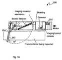
- FIG. 16is a pictorial illustration of a top view of the mobile digital tomography x-ray inspection system illustrated in FIG. 15;
- FIG. 16is a pictorial top view of the mobile digital tomography x-ray inspection system 250 ;
- FIG. 17illustrates an additional plan view illustrating the various components of the mobile system
- FIG. 18is a pictorial side view of the mobile system with its components stowed for transport.
- FIG. 19illustrates a CT imaging system that includes a plurality of sequentially operating x-ray guns.
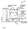
- FIG. 1illustrates a digital tomography system 20 that includes a rapidly moving x-ray source 22 .
- the source 22includes a high voltage electron accelerator, which is preferably a nested high voltage generator (NHVG) as disclosed in U.S. Pat. No. 5,124,658, incorporated herein by reference. It is contemplated that any other suitable electrostatic generator/accelerator may also be used.
- NHVGnested high voltage generator
- any other suitable electrostatic generator/acceleratormay also be used.
- the type of sourcewill depend of course on the type of object(s) the system is designed to inspect.
- the sourcein a medical imaging application the source may be a relatively low energy source (e.g., about 150 KeV), while in a contraband detection system designed to inspect shipping container or trucks the source may be a relatively high energy source (e.g., greater than about 1 MeV).
- a relatively low energy sourcee.g., about 150 KeV
- a relatively high energy sourcee.g., greater than about 1 MeV
- the source 22provides an electron beam 24 that enters a vacuum chamber 26 , which includes an electromagnet assembly. Magnetic steering of an electron beam to generate a scanning x-ray beam is disclosed in U.S. Pat. No. 6,009,146, which is incorporated herein by reference.
- a controller 30provides control signals on a line 32 to the electromagnet assembly to direct the electron beam 24 to strike a desired location on a target 34 (e.g., tungsten or gold) that emits a penetrating cone of x-rays 36 .
- the cone of x-rays 36 from the target 34enters a collimator 38 that includes a slit, from which an x-ray fan beam 40 exits and penetrates an object under inspection 42 .
- X-rays that pass through the object under inspection 42are detected by a line of detectors 44 (e.g., having 750 detectors spaced a known distance apart).
- a line of detectors 44e.g., having 750 detectors spaced a known distance apart.
- the electron beam 24is scanned across the target 34 to generate the fan beam 40 that moves in a first direction (e.g., laterally), while the object under inspection 42 moves in a second perpendicular direction (e.g., longitudinally) along a moving conveyer.
- FIG. 2illustrates how the fan beam is scanned and positioned at times t 1 and t 2 .
- the electron beamstrikes the target 34 at location 50 and generates the resultant cone of x-rays that is collimated to form a first fan beam 52 .
- the controller 30(FIG. 1) provides magnet control signals on the line 32 (FIG. 1) that drive the electromagnetic assembly to direct the electron beam to strike the target at location 54 .
- the resulting cone of x-raysis then collimated to form a second fan beam 56 .
- a first point 58 along the horizontal line 46 to be focusedis imaged by detector A 60
- the first pointis imaged by detector B 62 .
- an image of the desired horizontal plane 46is generated.
- the present inventionrapidly scans the electron beam 24 (FIG. 1) to generate a scanning fan beam of x-rays, which is used to generate an image utilizing the principals of digital tomography.
- FIG. 3illustrates an alternative embodiment digital tomography system 80 that includes a U-shaped detector 82 .
- the detector 82includes a first line of detectors 84 , a second line of detectors 86 and a third line of detectors 88 .
- the second and third lines of detectors 86 , 88are each substantially perpendicular to the first line of detectors 84 , and each line of detectors is configured and arranged to detect x-rays that pass through the object under inspection.
- FIG. 4illustrates an end view of a medical tomography imaging system 100 , suitable for quickly and inexpensively performing a full body scan of a patient (e.g., a trauma patient, such as a gun shot patient).
- This medical imaging system 100employs a relatively low peak energy x-ray source 102 , such as for example an x-ray tube (typically 160 kV).
- the x-ray source 102provides an electron beam within a vacuum chamber 103 that includes electromagnet assembly, which deflects (i.e., scans) the electron beam along a target 105 .
- the X-rays generated from the incident electrons striking the targetare collimated by a slit 104 and laterally scanned along a patient.
- a boom 104e.g., a “C-shaped boom” that supports the x-ray source and a line of detectors 108 is scanned over the patient head-to-toe (or visa-versa).
- the patientmay be placed on a moveable conveyor so the patient is scanned head-to-toe.
- FIG. 5illustrates a side view of the medical tomography system 100
- FIG. 6illustrates a perspective view of the system 100 .
- FIG. 7is a pictorial illustration of the source 102 , electromagnet assembly and the target 105 .
- Magnets 120 , 122receive control signals from the controller (FIG. 1 ).
- the targetis preferably oriented at a 7 degree angle.
- the sourcemay be placed below the patient, and the detectors above the patient.
- FIG. 8illustrates a digital tomography x-ray inspection system 150 for inspecting luggage.
- the system 150includes an x-ray source 152 that provides an electron beam that is magnetically deflected to strike a target at a desired location. The electron beam is deflected to scan along the target, in order to scan a collimated x-ray beam (e.g., a fan beam).
- the systemof course also includes a detector assembly 154 , which is preferably configured and arranged as a U-shaped detector assembly.
- the systemincludes a conveyor 156 that moves the luggage through the inspection system.
- FIG. 9is a pictorial illustration of a portion of a side view of the digital tomography x-ray inspection system 150 .
- the source 152Similar to the system illustrated in FIG. 7, the source 152 generates electron beam 160 , which is magnetically deflected to strike the target 162 , generating a cone of x-rays that is collimated to form the fan beam.
- the sourcemay be placed below the piece of luggage under inspection, and the detectors above the piece of luggage.
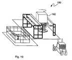
- FIG. 10is a pictorial illustration of a CT inspection system 180 suitable for inspecting air cargo containers 182 .
- the system 180includes a high energy electron source (e.g., a 1.5 MeV NHVG), which provides an electron beam that is magnetically deflected to scan along a target, generating a scanning x-ray beam.
- the system 180provides images of horizontal slices through the pallet as the pallet rotates and the electron beam is translated along the target.
- the system 180includes an elevator 184 that moves the pallet 182 vertically to form additional CT slices.
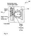
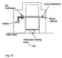
- FIG. 11is a plan view of the CT inspection system 180 suitable for inspecting air cargo containers. Electron beam 188 is magnetically deflected to translate along a target to generate a collimated x-ray beam 190 . A line to detectors 192 detects the x-rays that pass through he object under inspection, and provide detected signals to a controller/display system (not shown). FIG. 12 is an end view of the CT inspection system 180 .
- FIG. 13is an end view of digital tomography x-ray inspection system 200 for inspecting motor vehicles, such as for example trucks.
- the systemincludes a high energy electron source 202 that generates an electron beam 204 that is magnetically deflected within a vacuum to translate along a target and generate a cone of x-rays.
- the cone of x-raysare input to a collimator 206 to provide a fan beam that is vertically scanned.
- a line of detectors 210preferably configured as a substantially “L-shaped” detector, detects the x-rays and provides detected signals to a controller/image processor.
- FIG. 14is a pictorial illustration of an end view of the system 200 illustrating where the electron beam strikes the target at times t 1 and t 2 , and the associated detectors A and B, respectively, that are used to obtain an image of vertical plane 212 to be focused.
- the digital tomography x-ray inspection system 200 for inspecting motor vehiclesmay be either a stationary or mobile system.
- FIG. 15is a pictorial illustration of a mobile digital tomography x-ray inspection system 250 .
- This systemis substantially the same as the system illustrated in FIGS. 12 and 13, except that the system components have been mounted on a transport vehicle 252 .
- FIG. 16is a pictorial top view of the mobile digital tomography x-ray inspection system 250 .
- the systemincludes a boom assembly 253 on which the detectors are mounted.
- the boom 253is illustrated extending from the transport vehicle 252 and cooperatively positioned with respect to the fan beam 254 .
- the boom 253is also illustrated in phantom to show the transport position of the boom.
- FIG. 17illustrates an additional plan view illustrating the various components of the system.
- FIG. 18is a pictorial side view of the system 250 with its components stowed for transport.
- FIG. 19illustrates a CT imaging system 300 that includes a plurality of sequentially operating x-ray guns 302 - 309 (e.g., eight).
- Each of the xrays gun assemblies 302 - 309is substantially as shown in FIG. 7 .
- Each of the electron gun assembliesproduces an high current electron beam that impinges on an associated x-ray cathode, which produces a moving fan beam of x-rays as the electron beam moves rapidly over the cathode in a straight line.
- the poweris switched to the second electron gun 303 which continues to form the x-ray fan beam encircling the object under inspection.
- the poweris switched to the third electron gun 304 which continues to form the x-ray fan beam encircling the object under inspection.
- the electron gun assemblies 302 - 309are sequentially operated to form the desired image.
- each sourcemay be about 18 inches above its associated cathode.
- thisavoids spreading of the electron beam caused by coulomb repulsion between the electrons. This coulomb repulsion is worse as the beam length increases, hence the value of the short beam length.
- the fan beam of the x-raysis aimed slightly out of the plane of the paper so that it will intersect the array of fixed detectors, which are placed adjacent to the vacuum chamber.
- the systemalso includes an associated detector assembly 312 .
- each systemhas the common feature of an x-ray source that generates an electron beam that is rapidly deflected along a target material to generate the requisite penetrating X-rays.
Landscapes
- Health & Medical Sciences (AREA)
- Life Sciences & Earth Sciences (AREA)
- Engineering & Computer Science (AREA)
- Medical Informatics (AREA)
- Physics & Mathematics (AREA)
- High Energy & Nuclear Physics (AREA)
- Heart & Thoracic Surgery (AREA)
- Animal Behavior & Ethology (AREA)
- Optics & Photonics (AREA)
- Pathology (AREA)
- Radiology & Medical Imaging (AREA)
- Biomedical Technology (AREA)
- Biophysics (AREA)
- Molecular Biology (AREA)
- Surgery (AREA)
- Nuclear Medicine, Radiotherapy & Molecular Imaging (AREA)
- General Health & Medical Sciences (AREA)
- Public Health (AREA)
- Veterinary Medicine (AREA)
- Pulmonology (AREA)
- Theoretical Computer Science (AREA)
- General Life Sciences & Earth Sciences (AREA)
- General Physics & Mathematics (AREA)
- Geophysics (AREA)
- Analysing Materials By The Use Of Radiation (AREA)
Abstract
Description
This application claims priority from the provisional application designated Ser. No. 60/215,665 filed Jul. 1, 2000 and entitled “Imaging With Digital Tomography and a Rapidly Moving X-Ray Source”, and the provisional application designated Ser. No. 60/218,957 filed Jul. 17, 2000 and entitled “Imaging With Digital Tomography and a Rapidly Moving X-Ray Source”. Both applications are hereby incorporated by reference.
The invention relates to the field of x-ray imaging systems, and in particular to an x-ray imaging system that employs digital tomography and a rapidly moving x-ray source.
The original tomography systems employed an imaging technique wherein an x-ray source and a film mounted below the object under inspection (typically a person) were moved in opposed directions along prescribed paths so that only one plane of the object under inspection is in focus at all times. The motion of the x-ray source is in a plane parallel to the plane of the film. Structures in a slice parallel to the film plane projected onto the film in the same relative positions throughout the entire examination. All other planes above and below projected in different positions of the film at different times through the motion, and therefore were blurred. This system allowed the production of only a single slice of the object under inspection with each exposure to the cone of x-rays.
With the development of scintillating materials, solid state detectors and digital computers, linear digital tomography systems were developed using an x-ray source and collimator emitting a fan beam of x-rays incident on a line of detectors. The fan beam is translated along the line of detectors by physically moving the source, and every detector is sampled as the fan beam translates. It is then possible to later choose the proper set of detectors to read which will focus on a single line, parallel to the line of detectors. Because all of the data is stored, this line can be chosen at any distance between the x-ray source and the line of detectors.
A limitation of this prior art technique is that the x-ray source must be moved mechanically, and therefore slowly in order to translate the beam along the line of detectors. Thus, each line of data requires mechanical motion of the rather heavy x-ray source along the full dimension of the object being imaged. For example, if the motion of the source were to be accomplished in 1 second, and if one wished to have an image with 1000 pixels in the direction perpendicular to this motion, it would take 1000 seconds to complete an image. In addition, the complexity of such a mechanical moving system is considerable.
Therefore, there is a need for a x-ray imaging system, such as for example a digital tomography system, which rapidly positions the x-ray beam without having to mechanically scan/move the x-ray source over the object under inspection.
Briefly, according to an aspect of the invention, a digital tomography system includes an electron source that provides a beam of electrons, and an electromagnet assembly that receives said beam of electrons and is configured and arranged to direct the beam of electrons along a selected path, wherein the assembly provides a redirected beam of electrons. The system also includes a target that is struck by the redirected beam of electrons and generates a cone of x-rays, and a slit collimator that receives the cone of x-rays and generates a fan beam. A first line of detectors is positioned to detect x-rays that pass through the object under inspection, and provide sensed signals indicative thereof to a controller that receives the sensed signals and forms a displayable image of a selected plane through the object under inspection.
The digital tomography system can be configured and arranged for various applications including for example, medical applications and for contraband detection. For example, in a medical application the electron source would be rather low energy, such as a 150 KeV x-ray tube. In a contraband detection suitable for the inspection of cargo pallets and trucks, the electron source would be a rather high energy source, such as for example greater than one MeV. In addition, the system may be configured either as a stationary system or as a mobile system (e.g., mounted on a truck).
These and other objects, features and advantages of the present invention will become more apparent in light of the following detailed description of preferred embodiments thereof, as illustrated in the accompanying drawings.
FIG. 1 is a pictorial illustration of an x-ray imaging system suitable for inspecting a cargo pallet;
FIG. 2 is a pictorial illustration of the x-ray imaging system of FIG. 1 showing the fan beam position at times t1 and t2;
FIG. 3 is a pictorial illustration of an x-ray imaging system that includes a U-shaped detector;
FIG. 4 illustrates an end view of a medical tomography imaging system;
FIG. 5 illustrates a side view of the medical tomography system illustrated in FIG. 4;
FIG. 6 illustrates a perspective view of the system illustrated in FIGS. 4 and 5;
FIG. 7 is a pictorial illustration of the source, electromagnet assembly and thetarget 105 of the system illustrated in FIGS. 4-6;
FIG. 8 illustrates a digital tomography x-ray inspection system for inspecting luggage;
FIG. 9 is a pictorial illustration of a portion of a side view of the digital tomography x-ray inspection system illustrated in FIG. 8;
FIG. 10 is a pictorial illustration of a CT inspection system suitable for inspectingair cargo containers 182;
FIG. 11 is a plan view of the CT inspection system illustrated in FIG. 10;
FIG. 12 is an end view of the CT inspection system illustrated in FIGS. 10 and.11;
FIG. 13 is an end view of digital tomography x-ray inspection system for inspecting motor vehicles, such as for example trucks;
FIG. 14 is a pictorial illustration of an end view of the system illustrated in FIG. 13 illustrating where the electron beam strikes the target at times t1 and t2;
FIG. 15 is a pictorial illustration of a mobile digital tomography x-ray inspection system;
FIG. 16 is a pictorial illustration of a top view of the mobile digital tomography x-ray inspection system illustrated in FIG. 15;
FIG. 16 is a pictorial top view of the mobile digital tomographyx-ray inspection system 250;
FIG. 17 illustrates an additional plan view illustrating the various components of the mobile system;
FIG. 18 is a pictorial side view of the mobile system with its components stowed for transport; and
FIG. 19 illustrates a CT imaging system that includes a plurality of sequentially operating x-ray guns.
FIG. 1 illustrates adigital tomography system 20 that includes a rapidly movingx-ray source 22. In one embodiment, thesource 22 includes a high voltage electron accelerator, which is preferably a nested high voltage generator (NHVG) as disclosed in U.S. Pat. No. 5,124,658, incorporated herein by reference. It is contemplated that any other suitable electrostatic generator/accelerator may also be used. The type of source will depend of course on the type of object(s) the system is designed to inspect. For example, in a medical imaging application the source may be a relatively low energy source (e.g., about 150 KeV), while in a contraband detection system designed to inspect shipping container or trucks the source may be a relatively high energy source (e.g., greater than about 1 MeV).
Thesource 22 provides anelectron beam 24 that enters avacuum chamber 26, which includes an electromagnet assembly. Magnetic steering of an electron beam to generate a scanning x-ray beam is disclosed in U.S. Pat. No. 6,009,146, which is incorporated herein by reference. Acontroller 30 provides control signals on aline 32 to the electromagnet assembly to direct theelectron beam 24 to strike a desired location on a target34 (e.g., tungsten or gold) that emits a penetrating cone ofx-rays 36. The cone ofx-rays 36 from thetarget 34 enters acollimator 38 that includes a slit, from which anx-ray fan beam 40 exits and penetrates an object underinspection 42. X-rays that pass through the object underinspection 42 are detected by a line of detectors44 (e.g., having 750 detectors spaced a known distance apart). To image a line of a desiredhorizontal plane 46 of the object underinspection 42, theelectron beam 24 is scanned across thetarget 34 to generate thefan beam 40 that moves in a first direction (e.g., laterally), while the object underinspection 42 moves in a second perpendicular direction (e.g., longitudinally) along a moving conveyer.
FIG. 2 illustrates how the fan beam is scanned and positioned at times t1 and t2. Specifically, at time tl the electron beam strikes thetarget 34 atlocation 50 and generates the resultant cone of x-rays that is collimated to form afirst fan beam 52. At time t2 the controller30 (FIG. 1) provides magnet control signals on the line32 (FIG. 1) that drive the electromagnetic assembly to direct the electron beam to strike the target atlocation 54. The resulting cone of x-rays is then collimated to form asecond fan beam 56. At time t1, a first point58 along thehorizontal line 46 to be focused is imaged bydetector A 60, and at time t2 the first point is imaged bydetector B 62. Using known processing techniques an image of the desiredhorizontal plane 46 is generated.
Notably, the present invention rapidly scans the electron beam24 (FIG. 1) to generate a scanning fan beam of x-rays, which is used to generate an image utilizing the principals of digital tomography.
FIG. 3 illustrates an alternative embodimentdigital tomography system 80 that includes a U-shaped detector82. The detector82 includes a first line ofdetectors 84, a second line ofdetectors 86 and a third line ofdetectors 88. The second and third lines ofdetectors detectors 84, and each line of detectors is configured and arranged to detect x-rays that pass through the object under inspection.
FIG. 4 illustrates an end view of a medicaltomography imaging system 100, suitable for quickly and inexpensively performing a full body scan of a patient (e.g., a trauma patient, such as a gun shot patient). Thismedical imaging system 100 employs a relatively low peakenergy x-ray source 102, such as for example an x-ray tube (typically 160 kV). Thex-ray source 102 provides an electron beam within avacuum chamber 103 that includes electromagnet assembly, which deflects (i.e., scans) the electron beam along atarget 105. The X-rays generated from the incident electrons striking the target are collimated by aslit 104 and laterally scanned along a patient. While the x-ray beam is laterally scanning along the patient, a boom104 (e.g., a “C-shaped boom”) that supports the x-ray source and a line ofdetectors 108 is scanned over the patient head-to-toe (or visa-versa). Alternatively, the patient may be placed on a moveable conveyor so the patient is scanned head-to-toe.
FIG. 5 illustrates a side view of themedical tomography system 100, while FIG. 6 illustrates a perspective view of thesystem 100.
FIG. 7 is a pictorial illustration of thesource 102, electromagnet assembly and thetarget 105.Magnets
In an alternative medical tomography system embodiment, the source may be placed below the patient, and the detectors above the patient.
FIG. 8 illustrates a digital tomographyx-ray inspection system 150 for inspecting luggage. Thesystem 150 includes anx-ray source 152 that provides an electron beam that is magnetically deflected to strike a target at a desired location. The electron beam is deflected to scan along the target, in order to scan a collimated x-ray beam (e.g., a fan beam). The system of course also includes adetector assembly 154, which is preferably configured and arranged as a U-shaped detector assembly. In order to scan the entire piece of luggage, the system includes aconveyor 156 that moves the luggage through the inspection system.
FIG. 9 is a pictorial illustration of a portion of a side view of the digital tomographyx-ray inspection system 150. Similar to the system illustrated in FIG. 7, thesource 152 generateselectron beam 160, which is magnetically deflected to strike thetarget 162, generating a cone of x-rays that is collimated to form the fan beam. Of course in an alternative embodiment, the source may be placed below the piece of luggage under inspection, and the detectors above the piece of luggage.
FIG. 10 is a pictorial illustration of aCT inspection system 180 suitable for inspectingair cargo containers 182. Thesystem 180 includes a high energy electron source (e.g., a 1.5 MeV NHVG), which provides an electron beam that is magnetically deflected to scan along a target, generating a scanning x-ray beam. Thesystem 180 provides images of horizontal slices through the pallet as the pallet rotates and the electron beam is translated along the target. In addition, thesystem 180 includes anelevator 184 that moves thepallet 182 vertically to form additional CT slices.
FIG. 11 is a plan view of theCT inspection system 180 suitable for inspecting air cargo containers.Electron beam 188 is magnetically deflected to translate along a target to generate a collimated x-ray beam190. A line todetectors 192 detects the x-rays that pass through he object under inspection, and provide detected signals to a controller/display system (not shown). FIG. 12 is an end view of theCT inspection system 180.
FIG. 13 is an end view of digital tomographyx-ray inspection system 200 for inspecting motor vehicles, such as for example trucks. The system includes a highenergy electron source 202 that generates anelectron beam 204 that is magnetically deflected within a vacuum to translate along a target and generate a cone of x-rays. The cone of x-rays are input to a collimator206 to provide a fan beam that is vertically scanned. As the electron beam is being translated to form the vertically scanning fan beam, the motor vehicle is being moved through the inspection system. A line of detectors210 preferably configured as a substantially “L-shaped” detector, detects the x-rays and provides detected signals to a controller/image processor. FIG. 14 is a pictorial illustration of an end view of thesystem 200 illustrating where the electron beam strikes the target at times t1 and t2, and the associated detectors A and B, respectively, that are used to obtain an image ofvertical plane 212 to be focused.
Significantly, the digital tomographyx-ray inspection system 200 for inspecting motor vehicles may be either a stationary or mobile system. For example, FIG. 15 is a pictorial illustration of a mobile digital tomographyx-ray inspection system 250. This system is substantially the same as the system illustrated in FIGS. 12 and 13, except that the system components have been mounted on atransport vehicle 252. FIG. 16 is a pictorial top view of the mobile digital tomographyx-ray inspection system 250. The system includes aboom assembly 253 on which the detectors are mounted. Theboom 253 is illustrated extending from thetransport vehicle 252 and cooperatively positioned with respect to thefan beam 254. Theboom 253 is also illustrated in phantom to show the transport position of the boom. FIG. 17 illustrates an additional plan view illustrating the various components of the system. FIG. 18 is a pictorial side view of thesystem 250 with its components stowed for transport.
In another aspect of the invention, FIG. 19 illustrates a CT imaging system300 that includes a plurality of sequentially operating x-ray guns302-309 (e.g., eight). Each of the xrays gun assemblies302-309 is substantially as shown in FIG.7. Each of the electron gun assemblies produces an high current electron beam that impinges on an associated x-ray cathode, which produces a moving fan beam of x-rays as the electron beam moves rapidly over the cathode in a straight line. When the first electron gun assembly302 has traversed its associated cathode, the power is switched to thesecond electron gun 303 which continues to form the x-ray fan beam encircling the object under inspection. Similarly, once the secondelectron gun assembly 303 has traversed its associated cathode, the power is switched to thethird electron gun 304 which continues to form the x-ray fan beam encircling the object under inspection. The electron gun assemblies302-309 are sequentially operated to form the desired image.
In one embodiment, each source may be about 18 inches above its associated cathode. Advantageously, this avoids spreading of the electron beam caused by coulomb repulsion between the electrons. This coulomb repulsion is worse as the beam length increases, hence the value of the short beam length. The fan beam of the x-rays is aimed slightly out of the plane of the paper so that it will intersect the array of fixed detectors, which are placed adjacent to the vacuum chamber. Of course the system also includes an associateddetector assembly 312.
Although each of the systems disclosed herein has a different application, each system has the common feature of an x-ray source that generates an electron beam that is rapidly deflected along a target material to generate the requisite penetrating X-rays.
Although the present invention has been shown and described with respect to several preferred embodiments thereof, various changes, omissions and additions to the form and detail thereof, may be made therein, without departing from the spirit and scope of the invention.
Claims (14)
1. A digital tomography system, comprising:
an electron source that provides a pencil beam of electrons;
an electromagnet assembly that receives said pencil beam of electrons and is configured and arranged to direct said beam of electrons along a selected path, to bend said pencil beam of electrons and to scan the bended electron beam along a line to form a scanning redirected beam;
a linear target that is struck by said scanning redirected beam of electrons and generates a cone of x-rays that moves along a target line as a result of said scanning redirected beam;
a slit collimator that receives said scanning cone of x-rays and generates a scanning fan beam, which are directed to an object under inspection, wherein each point in the object under inspection receives x-rays from various angles;
a first line of detectors positioned in the same plane as the linear target to detect xrays that pass through the object under inspection, and provide sensed signals indicative thereof; and
a processing system that receives said sensed signals and forms a digital tomographic image of selected planes through the object under inspection.
2. The digital tomography system ofclaim 1 , wherein said electron source includes a high voltage electron accelerator.
3. The digital tomography system ofclaim 1 , wherein said electron source includes a nested high voltage electron generator.
4. The digital tomography system ofclaim 1 , wherein said first line of detectors includes a plurality of photo multiplier tubes.
5. The digital tomography system ofclaim 1 , further comprising a second line of detectors and a third line of detectors, each perpendicular to said first line of detectors, wherein said first, second and third line of detectors form a U-shaped detector configured and arranged to detect x-rays that pass through the object under inspection.
6. The digital tomography system ofclaim 1 , said first line of detectors includes a plurality of solid state detectors.
7. A computed tomography system, comprising:
means for providing a pencil beam of electrons;
means for receiving said pencil beans of electrons, for directing said beam of electrons along a selected path, and for bending said pencil beam of electrons and for scanning said bended electron beam along a line to form a scanning redirected beam;
a linear target that is struck by said scanning redirected beam of electrons and generates a cone of x-rays that moves along a target line as a result of said scanning redirected beam;
a collimator that receives said scanning cone of x-rays and generates a scanning fan beam directed to an object under inspection, wherein each point in the object under inspection receives x-rays from at least 180 degrees about the object under inspection;
a line of detectors positioned in the same plane as the linear target to detect x-rays that pass through the object under inspection, and provide sensed signals indicative thereof; and
a processing system that receives said sensed signals and forms a computed tomography image of selected planes through the object under inspection.
8. The computed tomography system ofclaim 7 , further comprising a platform that moves laterally and rotates, and onto which the object under inspection is placed.
9. The computed tomography system ofclaim 7 , wherein said means for providing a pencil beam of electrons is separated from said linear target by about 18 inches.
10. A computed tomography system, comprising:
a plurality of x-ray sources arranged around an object under inspection, each of said x-ray sources including
(i) means for providing a pencil beam of electrons;
(ii) an electromagnet assembly that receives said pencil beam of electrons and is configured and arranged to direct said beam of electrons along a selected path and bend said pencil beam of electrons and scans the bended electron beam along a line to form a scanning redirected beam;
(iii) a linear target that is struck by said scanning redirected beam of electrons and generates a cone of x-rays that moves along a target line as a result of said scanning redirected beam;
(iv) a slit collimator that receives said scanning cone of x-rays and generates a scanning fan beam directed to an object under inspection,
wherein said plurality of x-ray sources surround the object under inspection such that the object receives x-rays from at least 180 degrees about the object under inspection;
lines of detectors positioned to detect x-rays that pass through the object under inspection, and provide sensed signals indicative thereof; and
a computing device that receives said sensed signals to form a computed tomography image of the object under inspection.
11. The computed tomography system ofclaim 10 , wherein said detectors comprise a plurality of substantially U-shaped detectors that detect x-rays from each of said x-ray sources, wherein each of said U-shaped detectors includes first and second parallel detector arms separated by a perpendicular detector arm, each including a plurality of photodetective elements.
12. The computed tomography system ofclaim 10 , further comprising a platform that moves laterally and rotates, and onto which the object under inspection is placed.
13. The computed tomography system ofclaim 10 , wherein the object under inspection includes luggage.
14. The computed tomography system ofclaim 10 , wherein each means for providing a pencil beam of electrons is separated from its associated linear target by about 18 inches.
Priority Applications (2)
| Application Number | Priority Date | Filing Date | Title |
|---|---|---|---|
| US09/897,715US6628745B1 (en) | 2000-07-01 | 2001-07-02 | Imaging with digital tomography and a rapidly moving x-ray source |
| US10/288,244US6785360B1 (en) | 2001-07-02 | 2002-11-05 | Personnel inspection system with x-ray line source |
Applications Claiming Priority (3)
| Application Number | Priority Date | Filing Date | Title |
|---|---|---|---|
| US21566500P | 2000-07-01 | 2000-07-01 | |
| US21895700P | 2000-07-17 | 2000-07-17 | |
| US09/897,715US6628745B1 (en) | 2000-07-01 | 2001-07-02 | Imaging with digital tomography and a rapidly moving x-ray source |
Related Child Applications (1)
| Application Number | Title | Priority Date | Filing Date |
|---|---|---|---|
| US10/288,244Continuation-In-PartUS6785360B1 (en) | 2001-07-02 | 2002-11-05 | Personnel inspection system with x-ray line source |
Publications (1)
| Publication Number | Publication Date |
|---|---|
| US6628745B1true US6628745B1 (en) | 2003-09-30 |
Family
ID=28457720
Family Applications (1)
| Application Number | Title | Priority Date | Filing Date |
|---|---|---|---|
| US09/897,715Expired - Fee RelatedUS6628745B1 (en) | 2000-07-01 | 2001-07-02 | Imaging with digital tomography and a rapidly moving x-ray source |
Country Status (1)
| Country | Link |
|---|---|
| US (1) | US6628745B1 (en) |
Cited By (95)
| Publication number | Priority date | Publication date | Assignee | Title |
|---|---|---|---|---|
| US20030142784A1 (en)* | 2000-04-06 | 2003-07-31 | Makoto Suzuki | X-ray inspection system |
| US20040017888A1 (en)* | 2002-07-24 | 2004-01-29 | Seppi Edward J. | Radiation scanning of objects for contraband |
| US20040057554A1 (en)* | 2002-07-19 | 2004-03-25 | Paul Bjorkholm | Radiation sources and compact radiation scanning systems |
| US20040109532A1 (en)* | 2002-12-04 | 2004-06-10 | John Ford | Radiation scanning units including a movable platform |
| US20040156477A1 (en)* | 2003-01-31 | 2004-08-12 | Paul Bjorkholm | Radiation scanning of cargo conveyances at seaports and the like |
| US20040213375A1 (en)* | 2003-04-25 | 2004-10-28 | Paul Bjorkholm | Radiation sources and radiation scanning systems with improved uniformity of radiation intensity |
| US20040247075A1 (en)* | 2003-06-06 | 2004-12-09 | Johnson James H. | Vehicle mounted inspection systems and methods |
| US20050008124A1 (en)* | 2003-07-08 | 2005-01-13 | Christer Ullberg | Scanning-based detection of ionizing radiation for tomosynthesis |
| US20050031075A1 (en)* | 2003-08-07 | 2005-02-10 | Hopkins Forrest Frank | System and method for detecting an object |
| US20050031069A1 (en)* | 2003-08-07 | 2005-02-10 | General Electric Company | System and method for detecting an object by dynamically adjusting computational load |
| US20050058242A1 (en)* | 2003-09-15 | 2005-03-17 | Peschmann Kristian R. | Methods and systems for the rapid detection of concealed objects |
| US20050104001A1 (en)* | 2003-09-24 | 2005-05-19 | Radiation Monitoring Devices, Inc. | Very fast doped LaBr3 scintillators and time-of-flight PET |
| US20050117700A1 (en)* | 2003-08-08 | 2005-06-02 | Peschmann Kristian R. | Methods and systems for the rapid detection of concealed objects |
| US20050152491A1 (en)* | 2004-01-08 | 2005-07-14 | Tom Francke | Scanning-based detection of ionizing radiation for tomosynthesis |
| US20050157841A1 (en)* | 2004-01-15 | 2005-07-21 | Nasreen Chopra | Three-dimensional x-ray imaging system |
| US20050169556A1 (en)* | 2003-11-10 | 2005-08-04 | Yxlon International Security Gmbh | Method for deskewing an X-ray picture of an item of luggage |
| US20060008052A1 (en)* | 2004-02-06 | 2006-01-12 | Elyan Vladimir V | Non-intrusive inspection systems for large container screening and inspection |
| US6993111B1 (en)* | 2004-02-17 | 2006-01-31 | Martin Annis | Method and apparatus for improving the spatial resolution of a laminography system that employs an x-ray source with a scanning beam |
| US20060023835A1 (en)* | 2002-12-04 | 2006-02-02 | Seppi Edward J | Radiation scanning units with reduced detector requirements |
| US20060049359A1 (en)* | 2003-04-01 | 2006-03-09 | Cabot Microelectronics Corporation | Decontamination and sterilization system using large area x-ray source |
| US7012987B1 (en)* | 2004-01-20 | 2006-03-14 | Martin Annis | Method for preventing higher density regions of an object from degrading the lower density focused regions of a laminography image |
| US20060056595A1 (en)* | 2004-05-05 | 2006-03-16 | The Regents Of The University Of California | Compact X-ray source and panel |
| US7023950B1 (en)* | 2004-02-11 | 2006-04-04 | Martin Annis | Method and apparatus for determining the position of an x-ray cone beam produced by a scanning electron beam |
| US20060083351A1 (en)* | 2004-10-18 | 2006-04-20 | Ge Medical Systems Global Technology Company, Llc | Method and System for Scatter Correction During Bi-Plane Imaging with Simultaneous Exposure |
| US20060098773A1 (en)* | 2003-09-15 | 2006-05-11 | Peschmann Kristian R | Methods and systems for rapid detection of concealed objects using fluorescence |
| US20060210016A1 (en)* | 2005-03-17 | 2006-09-21 | Tom Francke | Scanning-based detection of ionizing radiation for tomosynthesis |
| US20060291628A1 (en)* | 2005-06-24 | 2006-12-28 | Clayton James E | X-ray radiation sources with low neutron emissions for radiation scanning |
| US20070081623A1 (en)* | 2005-07-05 | 2007-04-12 | L-3 Communications Security And Detection Systems, Inc. | Methods and apparatus for e-beam scanning |
| US7221732B1 (en)* | 2005-04-04 | 2007-05-22 | Martin Annis | Method and apparatus for producing laminography images using a fixed x-ray source |
| US20070165773A1 (en)* | 2004-04-28 | 2007-07-19 | Koninklijke Philips Electronics N.V. | Three-dimensional electron beam computed tomography |
| US20070280408A1 (en)* | 2006-04-14 | 2007-12-06 | Tiezhi Zhang | Scanning slot cone-beam computed tomography and scanning focus spot cone-beam computed tomography |
| US20080075230A1 (en)* | 2006-09-21 | 2008-03-27 | L-3 Communications Security and Detection Systems Inc. | Compact e-beam source for generating X-rays |
| US20080170655A1 (en)* | 2007-01-17 | 2008-07-17 | Ge Homeland Protection, Inc. | Computed tomography cargo inspection system and method |
| US20090003514A1 (en)* | 2007-06-29 | 2009-01-01 | General Electric Company | Integrated multi-sensor systems for and methods of explosives detection |
| US20090010386A1 (en)* | 2003-09-15 | 2009-01-08 | Peschmann Kristian R | Methods and Systems for Rapid Detection of Concealed Objects Using Fluorescence |
| US20090086906A1 (en)* | 2007-09-28 | 2009-04-02 | Clayton James E | Radiation scanning with photon tagging |
| US20090092228A1 (en)* | 2005-06-29 | 2009-04-09 | Accuray Incorporated | Imaging geometry for image-guided radiosurgery |
| US7529336B2 (en) | 2007-05-31 | 2009-05-05 | Test Research, Inc. | System and method for laminography inspection |
| US20090116617A1 (en)* | 2004-04-09 | 2009-05-07 | American Science And Engineering, Inc. | Multiple Image Collection and Synthesis for Personnel Screening |
| US20090268869A1 (en)* | 2006-05-27 | 2009-10-29 | X-Tek Systems Limited | X-Ray Inspection System and Method |
| US20100014638A1 (en)* | 2008-07-16 | 2010-01-21 | L-3 Communications Security and Detection Systems, | Irradiation system including an electron-beam scanner |
| WO2010029862A1 (en)* | 2008-09-10 | 2010-03-18 | オムロン株式会社 | X-ray inspection device and method for x-ray inspection |
| US20100127169A1 (en)* | 2008-11-24 | 2010-05-27 | Varian Medical Systems, Inc. | Compact, interleaved radiation sources |
| WO2010074030A1 (en)* | 2008-12-22 | 2010-07-01 | オムロン株式会社 | X-ray inspection method and x-ray inspection apparatus |
| WO2010074031A1 (en)* | 2008-12-22 | 2010-07-01 | オムロン株式会社 | X-ray inspection method and x-ray inspection apparatus |
| US20100284509A1 (en)* | 2009-05-08 | 2010-11-11 | Boris Oreper | Dual energy imaging system |
| US20100329532A1 (en)* | 2007-12-27 | 2010-12-30 | Omron Corporation | X-ray inspecting apparatus and x-ray inspecting method |
| US7929664B2 (en) | 2007-02-13 | 2011-04-19 | Sentinel Scanning Corporation | CT scanning and contraband detection |
| US8340245B2 (en) | 2009-06-05 | 2012-12-25 | Sentinel Scanning Corporation | Transportation container inspection system and method |
| US8576982B2 (en) | 2008-02-01 | 2013-11-05 | Rapiscan Systems, Inc. | Personnel screening system |
| US8576989B2 (en) | 2010-03-14 | 2013-11-05 | Rapiscan Systems, Inc. | Beam forming apparatus |
| US8670523B2 (en) | 2010-01-05 | 2014-03-11 | William Beaumont Hospital | Intensity modulated arc therapy with continuous couch rotation/shift and simultaneous cone beam imaging |
| US8724872B1 (en)* | 2009-02-25 | 2014-05-13 | L-3 Communications Security And Detection Systems, Inc. | Single radiation data from multiple radiation sources |
| US8837669B2 (en) | 2003-04-25 | 2014-09-16 | Rapiscan Systems, Inc. | X-ray scanning system |
| US20140294147A1 (en)* | 2013-03-15 | 2014-10-02 | Varian Medical Systems, Inc. | Systems and methods for multi-view imaging and tomography |
| US8885794B2 (en) | 2003-04-25 | 2014-11-11 | Rapiscan Systems, Inc. | X-ray tomographic inspection system for the identification of specific target items |
| US8983024B2 (en) | 2006-04-14 | 2015-03-17 | William Beaumont Hospital | Tetrahedron beam computed tomography with multiple detectors and/or source arrays |
| US8995619B2 (en) | 2010-03-14 | 2015-03-31 | Rapiscan Systems, Inc. | Personnel screening system |
| US9020095B2 (en) | 2003-04-25 | 2015-04-28 | Rapiscan Systems, Inc. | X-ray scanners |
| US9048061B2 (en) | 2005-12-16 | 2015-06-02 | Rapiscan Systems, Inc. | X-ray scanners and X-ray sources therefor |
| US9057679B2 (en) | 2012-02-03 | 2015-06-16 | Rapiscan Systems, Inc. | Combined scatter and transmission multi-view imaging system |
| US9069092B2 (en) | 2012-02-22 | 2015-06-30 | L-3 Communication Security and Detection Systems Corp. | X-ray imager with sparse detector array |
| EP2889652A1 (en)* | 2013-12-30 | 2015-07-01 | Nuctech Company Limited | X-ray fluoroscopic imaging system |
| EP2889651A1 (en)* | 2013-12-30 | 2015-07-01 | Nuctech Company Limited | X-ray fluoroscopic imaging system |
| US9113839B2 (en) | 2003-04-25 | 2015-08-25 | Rapiscon Systems, Inc. | X-ray inspection system and method |
| US20150279496A1 (en)* | 2012-03-25 | 2015-10-01 | Arp Angewandte Radiologische Physik Ug (Haftungsbeschrankt) | Phase Contrast X-Ray Tomography Device |
| US9192786B2 (en) | 2006-05-25 | 2015-11-24 | William Beaumont Hospital | Real-time, on-line and offline treatment dose tracking and feedback process for volumetric image guided adaptive radiotherapy |
| US20160027606A1 (en)* | 2013-04-09 | 2016-01-28 | Helmholtz-Zentrum Dresden-Rossendorf E.V. | Arrangement for a quick electron beam x-ray computer tomography |
| WO2015195570A3 (en)* | 2014-06-16 | 2016-03-10 | Loma Linda University | Radiography and computed tomography with high-energy electron beams |
| US9285325B2 (en) | 2007-02-01 | 2016-03-15 | Rapiscan Systems, Inc. | Personnel screening system |
| US9310323B2 (en) | 2009-05-16 | 2016-04-12 | Rapiscan Systems, Inc. | Systems and methods for high-Z threat alarm resolution |
| US9339243B2 (en) | 2006-04-14 | 2016-05-17 | William Beaumont Hospital | Image guided radiotherapy with dual source and dual detector arrays tetrahedron beam computed tomography |
| US9500601B2 (en) | 2013-03-16 | 2016-11-22 | Lawrence Livermore National Security, Llc | Adaptive CT scanning system |
| US9557427B2 (en) | 2014-01-08 | 2017-01-31 | Rapiscan Systems, Inc. | Thin gap chamber neutron detectors |
| US9632206B2 (en) | 2011-09-07 | 2017-04-25 | Rapiscan Systems, Inc. | X-ray inspection system that integrates manifest data with imaging/detection processing |
| US9791590B2 (en) | 2013-01-31 | 2017-10-17 | Rapiscan Systems, Inc. | Portable security inspection system |
| US9823383B2 (en) | 2013-01-07 | 2017-11-21 | Rapiscan Systems, Inc. | X-ray scanner with partial energy discriminating detector array |
| US20180017702A1 (en)* | 2016-07-14 | 2018-01-18 | Rapiscan Systems, Inc. | Systems and Methods for Improving Penetration of Radiographic Scanners |
| US9880301B2 (en) | 2011-03-07 | 2018-01-30 | Loma Linda University Medical Center | Systems, devices and methods related to calibration of a proton computed tomography scanner |
| US9891314B2 (en) | 2014-03-07 | 2018-02-13 | Rapiscan Systems, Inc. | Ultra wide band detectors |
| US10134254B2 (en) | 2014-11-25 | 2018-11-20 | Rapiscan Systems, Inc. | Intelligent security management system |
| US10180505B2 (en) | 2010-02-12 | 2019-01-15 | Loma Linda University Medical Center | Systems and methodologies for proton computed tomography |
| US10295483B2 (en) | 2005-12-16 | 2019-05-21 | Rapiscan Systems, Inc. | Data collection, processing and storage systems for X-ray tomographic images |
| US10302807B2 (en) | 2016-02-22 | 2019-05-28 | Rapiscan Systems, Inc. | Systems and methods for detecting threats and contraband in cargo |
| US10345479B2 (en) | 2015-09-16 | 2019-07-09 | Rapiscan Systems, Inc. | Portable X-ray scanner |
| US10393676B2 (en)* | 2008-11-11 | 2019-08-27 | Hamamatsu Photonics K.K. | Radiation detection device, radiation image acquiring system, radiation inspection system, and radiation detection method |
| US10591424B2 (en) | 2003-04-25 | 2020-03-17 | Rapiscan Systems, Inc. | X-ray tomographic inspection systems for the identification of specific target items |
| US10600609B2 (en) | 2017-01-31 | 2020-03-24 | Rapiscan Systems, Inc. | High-power X-ray sources and methods of operation |
| US20200182807A1 (en)* | 2018-12-10 | 2020-06-11 | KUB Technologies, Inc. | System and method for cabinet x-ray systems with stationary x-ray source array |
| US10720300B2 (en) | 2016-09-30 | 2020-07-21 | American Science And Engineering, Inc. | X-ray source for 2D scanning beam imaging |
| EP2526410B1 (en)* | 2010-01-19 | 2021-10-20 | Rapiscan Systems, Inc. | Multi-view cargo scanner |
| US11280898B2 (en) | 2014-03-07 | 2022-03-22 | Rapiscan Systems, Inc. | Radar-based baggage and parcel inspection systems |
| US20240094147A1 (en)* | 2022-09-16 | 2024-03-21 | Rapiscan Holdings, Inc. | Systems and Methods for Generating High-Energy Three-Dimensional Computed Tomography Images of Bulk Materials |
| US12181422B2 (en) | 2019-09-16 | 2024-12-31 | Rapiscan Holdings, Inc. | Probabilistic image analysis |
| US12283389B2 (en) | 2021-10-01 | 2025-04-22 | Rapiscan Holdings, Inc. | Methods and systems for the concurrent generation of multiple substantially similar X-ray beams |
Citations (9)
| Publication number | Priority date | Publication date | Assignee | Title |
|---|---|---|---|---|
| US4352021A (en)* | 1980-01-07 | 1982-09-28 | The Regents Of The University Of California | X-Ray transmission scanning system and method and electron beam X-ray scan tube for use therewith |
| US4521901A (en)* | 1983-03-01 | 1985-06-04 | Imatron Associates | Scanning electron beam computed tomography scanner with ion aided focusing |
| US4989225A (en)* | 1988-08-18 | 1991-01-29 | Bio-Imaging Research, Inc. | Cat scanner with simultaneous translation and rotation of objects |
| US5119408A (en)* | 1990-10-31 | 1992-06-02 | General Electric Company | Rotate/rotate method and apparatus for computed tomography x-ray inspection of large objects |
| US5199054A (en)* | 1990-08-30 | 1993-03-30 | Four Pi Systems Corporation | Method and apparatus for high resolution inspection of electronic items |
| US5583904A (en)* | 1995-04-11 | 1996-12-10 | Hewlett-Packard Co. | Continuous linear scan laminography system and method |
| US6236709B1 (en)* | 1998-05-04 | 2001-05-22 | Ensco, Inc. | Continuous high speed tomographic imaging system and method |
| US6324249B1 (en)* | 2001-03-21 | 2001-11-27 | Agilent Technologies, Inc. | Electronic planar laminography system and method |
| US6501822B2 (en)* | 2000-08-30 | 2002-12-31 | Agilent Technologies, Inc. | Z-axis elimination in an X-ray laminography system using image magnification for Z plane adjustment |
- 2001
- 2001-07-02USUS09/897,715patent/US6628745B1/ennot_activeExpired - Fee Related
Patent Citations (9)
| Publication number | Priority date | Publication date | Assignee | Title |
|---|---|---|---|---|
| US4352021A (en)* | 1980-01-07 | 1982-09-28 | The Regents Of The University Of California | X-Ray transmission scanning system and method and electron beam X-ray scan tube for use therewith |
| US4521901A (en)* | 1983-03-01 | 1985-06-04 | Imatron Associates | Scanning electron beam computed tomography scanner with ion aided focusing |
| US4989225A (en)* | 1988-08-18 | 1991-01-29 | Bio-Imaging Research, Inc. | Cat scanner with simultaneous translation and rotation of objects |
| US5199054A (en)* | 1990-08-30 | 1993-03-30 | Four Pi Systems Corporation | Method and apparatus for high resolution inspection of electronic items |
| US5119408A (en)* | 1990-10-31 | 1992-06-02 | General Electric Company | Rotate/rotate method and apparatus for computed tomography x-ray inspection of large objects |
| US5583904A (en)* | 1995-04-11 | 1996-12-10 | Hewlett-Packard Co. | Continuous linear scan laminography system and method |
| US6236709B1 (en)* | 1998-05-04 | 2001-05-22 | Ensco, Inc. | Continuous high speed tomographic imaging system and method |
| US6501822B2 (en)* | 2000-08-30 | 2002-12-31 | Agilent Technologies, Inc. | Z-axis elimination in an X-ray laminography system using image magnification for Z plane adjustment |
| US6324249B1 (en)* | 2001-03-21 | 2001-11-27 | Agilent Technologies, Inc. | Electronic planar laminography system and method |
Cited By (219)
| Publication number | Priority date | Publication date | Assignee | Title |
|---|---|---|---|---|
| US7356117B2 (en) | 2000-04-06 | 2008-04-08 | Hamamatsu Photonics K.K. | X-ray inspection system |
| US20050100130A1 (en)* | 2000-04-06 | 2005-05-12 | Hamamatsu Photonics K.K. | X-ray inspection system |
| US6876722B2 (en)* | 2000-04-06 | 2005-04-05 | Hamamatsu Photonics K.K. | X-ray inspection system |
| US20030142784A1 (en)* | 2000-04-06 | 2003-07-31 | Makoto Suzuki | X-ray inspection system |
| US20040057554A1 (en)* | 2002-07-19 | 2004-03-25 | Paul Bjorkholm | Radiation sources and compact radiation scanning systems |
| US7162005B2 (en)* | 2002-07-19 | 2007-01-09 | Varian Medical Systems Technologies, Inc. | Radiation sources and compact radiation scanning systems |
| US20090067575A1 (en)* | 2002-07-24 | 2009-03-12 | Seppi Edward E | Radiation scanning units including a movable platform |
| US7672422B2 (en) | 2002-07-24 | 2010-03-02 | Varian Medical Systems, Inc. | Radiation scanning of objects for contraband |
| US8000436B2 (en) | 2002-07-24 | 2011-08-16 | Varian Medical Systems, Inc. | Radiation scanning units including a movable platform |
| US20080205583A1 (en)* | 2002-07-24 | 2008-08-28 | Seppi Edward J | Radiation scanning of objects for contraband |
| US7369640B2 (en)* | 2002-07-24 | 2008-05-06 | Varian Medical Systems Technologies, Inc. | Radiation scanning of objects for contraband |
| US7103137B2 (en)* | 2002-07-24 | 2006-09-05 | Varian Medical Systems Technology, Inc. | Radiation scanning of objects for contraband |
| US20070003003A1 (en)* | 2002-07-24 | 2007-01-04 | Seppi Edward J | Radiation scanning of objects for contraband |
| WO2004010127A1 (en)* | 2002-07-24 | 2004-01-29 | Varian Medical Systems Inc. | Radiation scanning of objects for contraband |
| US20040017888A1 (en)* | 2002-07-24 | 2004-01-29 | Seppi Edward J. | Radiation scanning of objects for contraband |
| US7672426B2 (en) | 2002-12-04 | 2010-03-02 | Varian Medical Systems, Inc. | Radiation scanning units with reduced detector requirements |
| US7356115B2 (en)* | 2002-12-04 | 2008-04-08 | Varian Medical Systems Technology, Inc. | Radiation scanning units including a movable platform |
| US20060023835A1 (en)* | 2002-12-04 | 2006-02-02 | Seppi Edward J | Radiation scanning units with reduced detector requirements |
| US20040109532A1 (en)* | 2002-12-04 | 2004-06-10 | John Ford | Radiation scanning units including a movable platform |
| US7274767B2 (en) | 2003-01-31 | 2007-09-25 | Varian Medical Systems Technologies, Inc. | Rotating carriage assembly for use in scanning cargo conveyances transported by a crane |
| US7783003B2 (en) | 2003-01-31 | 2010-08-24 | Varian Medical Systems, Inc. | Rotating carriage assembly for use in scanning cargo conveyances transported by a crane |
| US7317782B2 (en) | 2003-01-31 | 2008-01-08 | Varian Medical Systems Technologies, Inc. | Radiation scanning of cargo conveyances at seaports and the like |
| US20080084963A1 (en)* | 2003-01-31 | 2008-04-10 | Clayton James E | Rotating carriage assembly for use in scanning cargo conveyances transported by a crane |
| US20060115043A1 (en)* | 2003-01-31 | 2006-06-01 | Clayton James E | Rotating carriage assembly for use in scanning cargo conveyances transported by a crane |
| US20040156477A1 (en)* | 2003-01-31 | 2004-08-12 | Paul Bjorkholm | Radiation scanning of cargo conveyances at seaports and the like |
| US20060049359A1 (en)* | 2003-04-01 | 2006-03-09 | Cabot Microelectronics Corporation | Decontamination and sterilization system using large area x-ray source |
| US7447298B2 (en) | 2003-04-01 | 2008-11-04 | Cabot Microelectronics Corporation | Decontamination and sterilization system using large area x-ray source |
| US9113839B2 (en) | 2003-04-25 | 2015-08-25 | Rapiscon Systems, Inc. | X-ray inspection system and method |
| US20040213375A1 (en)* | 2003-04-25 | 2004-10-28 | Paul Bjorkholm | Radiation sources and radiation scanning systems with improved uniformity of radiation intensity |
| US10901112B2 (en) | 2003-04-25 | 2021-01-26 | Rapiscan Systems, Inc. | X-ray scanning system with stationary x-ray sources |
| US9020095B2 (en) | 2003-04-25 | 2015-04-28 | Rapiscan Systems, Inc. | X-ray scanners |
| US10591424B2 (en) | 2003-04-25 | 2020-03-17 | Rapiscan Systems, Inc. | X-ray tomographic inspection systems for the identification of specific target items |
| US11796711B2 (en) | 2003-04-25 | 2023-10-24 | Rapiscan Systems, Inc. | Modular CT scanning system |
| US8885794B2 (en) | 2003-04-25 | 2014-11-11 | Rapiscan Systems, Inc. | X-ray tomographic inspection system for the identification of specific target items |
| US10175381B2 (en) | 2003-04-25 | 2019-01-08 | Rapiscan Systems, Inc. | X-ray scanners having source points with less than a predefined variation in brightness |
| US8837669B2 (en) | 2003-04-25 | 2014-09-16 | Rapiscan Systems, Inc. | X-ray scanning system |
| US9618648B2 (en) | 2003-04-25 | 2017-04-11 | Rapiscan Systems, Inc. | X-ray scanners |
| US6954515B2 (en)* | 2003-04-25 | 2005-10-11 | Varian Medical Systems, Inc., | Radiation sources and radiation scanning systems with improved uniformity of radiation intensity |
| WO2004097337A1 (en)* | 2003-04-25 | 2004-11-11 | Varian Medical Systems Technologies, Inc. | Radiation sources and radiation scanning systems with improved uniformity of radiation intensity |
| US9442082B2 (en) | 2003-04-25 | 2016-09-13 | Rapiscan Systems, Inc. | X-ray inspection system and method |
| US9675306B2 (en) | 2003-04-25 | 2017-06-13 | Rapiscan Systems, Inc. | X-ray scanning system |
| US20050281390A1 (en)* | 2003-06-06 | 2005-12-22 | Johnson James H | Vehicle mounted inspection systems and methods |
| US6937692B2 (en) | 2003-06-06 | 2005-08-30 | Varian Medical Systems Technologies, Inc. | Vehicle mounted inspection systems and methods |
| US7397891B2 (en) | 2003-06-06 | 2008-07-08 | Varian Medical Systems Technologies, Inc. | Vehicle mounted inspection systems and methods |
| US20040247075A1 (en)* | 2003-06-06 | 2004-12-09 | Johnson James H. | Vehicle mounted inspection systems and methods |
| US20050008124A1 (en)* | 2003-07-08 | 2005-01-13 | Christer Ullberg | Scanning-based detection of ionizing radiation for tomosynthesis |
| US6940942B2 (en) | 2003-07-08 | 2005-09-06 | Xcounter Ab | Scanning-based detection of ionizing radiation for tomosynthesis |
| US20050031075A1 (en)* | 2003-08-07 | 2005-02-10 | Hopkins Forrest Frank | System and method for detecting an object |
| US20050031069A1 (en)* | 2003-08-07 | 2005-02-10 | General Electric Company | System and method for detecting an object by dynamically adjusting computational load |
| US7492855B2 (en)* | 2003-08-07 | 2009-02-17 | General Electric Company | System and method for detecting an object |
| US7889835B2 (en) | 2003-08-07 | 2011-02-15 | Morpho Detection, Inc. | System and method for detecting an object by dynamically adjusting computational load |
| US9042511B2 (en) | 2003-08-08 | 2015-05-26 | Rapiscan Systems, Inc. | Methods and systems for the rapid detection of concealed objects |
| US20050117700A1 (en)* | 2003-08-08 | 2005-06-02 | Peschmann Kristian R. | Methods and systems for the rapid detection of concealed objects |
| US9915752B2 (en) | 2003-08-08 | 2018-03-13 | Rapiscan Systems, Inc. | Inspection systems with two X-ray scanners in a first stage inspection system |
| US20090010386A1 (en)* | 2003-09-15 | 2009-01-08 | Peschmann Kristian R | Methods and Systems for Rapid Detection of Concealed Objects Using Fluorescence |
| US20050058242A1 (en)* | 2003-09-15 | 2005-03-17 | Peschmann Kristian R. | Methods and systems for the rapid detection of concealed objects |
| US20110228896A1 (en)* | 2003-09-15 | 2011-09-22 | Peschmann Kristian R | Methods and Systems for Rapid Detection of Concealed Objects Using Fluorescence |
| US7366282B2 (en)* | 2003-09-15 | 2008-04-29 | Rapiscan Security Products, Inc. | Methods and systems for rapid detection of concealed objects using fluorescence |
| US8428217B2 (en) | 2003-09-15 | 2013-04-23 | Rapiscan Systems, Inc. | Methods and systems for rapid detection of concealed objects |
| US9268058B2 (en) | 2003-09-15 | 2016-02-23 | Rapiscan Systems, Inc. | Methods and systems for the rapid detection of concealed objects |
| US20060098773A1 (en)* | 2003-09-15 | 2006-05-11 | Peschmann Kristian R | Methods and systems for rapid detection of concealed objects using fluorescence |
| US7856081B2 (en)* | 2003-09-15 | 2010-12-21 | Rapiscan Systems, Inc. | Methods and systems for rapid detection of concealed objects using fluorescence |
| US7129494B2 (en)* | 2003-09-24 | 2006-10-31 | Radiation Monitoring Devices, Inc. | Very fast doped LaBr3 scintillators and time-of-flight PET |
| US20050104001A1 (en)* | 2003-09-24 | 2005-05-19 | Radiation Monitoring Devices, Inc. | Very fast doped LaBr3 scintillators and time-of-flight PET |
| US7162006B2 (en)* | 2003-11-10 | 2007-01-09 | Yxlon International Security Gmbh | Method for de-skewing an X-ray picture of an item of luggage |
| US20050169556A1 (en)* | 2003-11-10 | 2005-08-04 | Yxlon International Security Gmbh | Method for deskewing an X-ray picture of an item of luggage |
| US7020237B2 (en) | 2004-01-08 | 2006-03-28 | Xcounter Ab | Scanning-based detection of ionizing radiation for tomosynthesis |
| US20050152491A1 (en)* | 2004-01-08 | 2005-07-14 | Tom Francke | Scanning-based detection of ionizing radiation for tomosynthesis |
| US7010086B2 (en)* | 2004-01-15 | 2006-03-07 | Agilent Technologies, Inc. | Three-dimensional x-ray imaging system |
| US20050157841A1 (en)* | 2004-01-15 | 2005-07-21 | Nasreen Chopra | Three-dimensional x-ray imaging system |
| US7012987B1 (en)* | 2004-01-20 | 2006-03-14 | Martin Annis | Method for preventing higher density regions of an object from degrading the lower density focused regions of a laminography image |
| US20060008052A1 (en)* | 2004-02-06 | 2006-01-12 | Elyan Vladimir V | Non-intrusive inspection systems for large container screening and inspection |
| US7162007B2 (en)* | 2004-02-06 | 2007-01-09 | Elyan Vladimir V | Non-intrusive inspection systems for large container screening and inspection |
| US7023950B1 (en)* | 2004-02-11 | 2006-04-04 | Martin Annis | Method and apparatus for determining the position of an x-ray cone beam produced by a scanning electron beam |
| US6993111B1 (en)* | 2004-02-17 | 2006-01-31 | Martin Annis | Method and apparatus for improving the spatial resolution of a laminography system that employs an x-ray source with a scanning beam |
| US20100104069A1 (en)* | 2004-04-09 | 2010-04-29 | American Science And Engineering, Inc. | Multiple Image Collection and Synthesis for Personnel Screening |
| US7796734B2 (en) | 2004-04-09 | 2010-09-14 | American Science And Engineering, Inc. | Multiple image collection and synthesis for personnel screening |
| US20090116617A1 (en)* | 2004-04-09 | 2009-05-07 | American Science And Engineering, Inc. | Multiple Image Collection and Synthesis for Personnel Screening |
| US20110017917A1 (en)* | 2004-04-09 | 2011-01-27 | American Science And Engineering, Inc. | Multiple Image Collection and Synthesis for Personnel Screening |
| US9020100B2 (en) | 2004-04-09 | 2015-04-28 | America Science and Engineering, Inc. | Multiple image collection and synthesis for personnel screening |
| US8605859B2 (en) | 2004-04-09 | 2013-12-10 | American Science And Engineering, Inc. | Multiple image collection and synthesis for personnel screening |
| US20110164726A1 (en)* | 2004-04-09 | 2011-07-07 | American Science And Engineering, Inc. | Multiple Image Collection and Synthesis for Personnel Screening |
| US7809109B2 (en) | 2004-04-09 | 2010-10-05 | American Science And Engineering, Inc. | Multiple image collection and synthesis for personnel screening |
| US7688937B2 (en) | 2004-04-28 | 2010-03-30 | Koninklijke Philips Electronics N.V. | Three dimensional electron beam computed tomography |
| US20070165773A1 (en)* | 2004-04-28 | 2007-07-19 | Koninklijke Philips Electronics N.V. | Three-dimensional electron beam computed tomography |
| US20060056595A1 (en)* | 2004-05-05 | 2006-03-16 | The Regents Of The University Of California | Compact X-ray source and panel |
| US7330533B2 (en) | 2004-05-05 | 2008-02-12 | Lawrence Livermore National Security, Llc | Compact x-ray source and panel |
| US20060083351A1 (en)* | 2004-10-18 | 2006-04-20 | Ge Medical Systems Global Technology Company, Llc | Method and System for Scatter Correction During Bi-Plane Imaging with Simultaneous Exposure |
| US20060210016A1 (en)* | 2005-03-17 | 2006-09-21 | Tom Francke | Scanning-based detection of ionizing radiation for tomosynthesis |
| US7221732B1 (en)* | 2005-04-04 | 2007-05-22 | Martin Annis | Method and apparatus for producing laminography images using a fixed x-ray source |
| US7783010B2 (en) | 2005-06-24 | 2010-08-24 | Varian Medical Systems, Inc. | X-ray radiation sources with low neutron emissions for radiation scanning |
| US20060291628A1 (en)* | 2005-06-24 | 2006-12-28 | Clayton James E | X-ray radiation sources with low neutron emissions for radiation scanning |
| US20090041197A1 (en)* | 2005-06-24 | 2009-02-12 | Clayton James E | X-ray radiation sources with low neutron emissions for radiation scanning |
| US7436932B2 (en) | 2005-06-24 | 2008-10-14 | Varian Medical Systems Technologies, Inc. | X-ray radiation sources with low neutron emissions for radiation scanning |
| US20090092228A1 (en)* | 2005-06-29 | 2009-04-09 | Accuray Incorporated | Imaging geometry for image-guided radiosurgery |
| WO2007006042A3 (en)* | 2005-07-05 | 2007-06-07 | L 3 Comm Security & Detection | Methods and apparatus for e-beam scanning |
| US8155272B2 (en) | 2005-07-05 | 2012-04-10 | L-3 Communications Security and Detection Systems Inc. | Methods and apparatus for e-beam scanning |
| US7428297B2 (en) | 2005-07-05 | 2008-09-23 | L-3 Communications Security And Detection Systems, Inc. | Methods and apparatus for e-beam scanning |
| US20070081623A1 (en)* | 2005-07-05 | 2007-04-12 | L-3 Communications Security And Detection Systems, Inc. | Methods and apparatus for e-beam scanning |
| US20100316188A1 (en)* | 2005-07-05 | 2010-12-16 | L-3 Communications Security and Detection Systems Inc. | Methods and apparatus for e-beam scanning |
| US7180977B2 (en) | 2005-10-24 | 2007-02-20 | Xcounter Ab | Scanning-based detection of ionizing radiaion for tomosynthesis |
| US10976271B2 (en) | 2005-12-16 | 2021-04-13 | Rapiscan Systems, Inc. | Stationary tomographic X-ray imaging systems for automatically sorting objects based on generated tomographic images |
| US9048061B2 (en) | 2005-12-16 | 2015-06-02 | Rapiscan Systems, Inc. | X-ray scanners and X-ray sources therefor |
| US9638646B2 (en) | 2005-12-16 | 2017-05-02 | Rapiscan Systems, Inc. | X-ray scanners and X-ray sources therefor |
| US10295483B2 (en) | 2005-12-16 | 2019-05-21 | Rapiscan Systems, Inc. | Data collection, processing and storage systems for X-ray tomographic images |
| US20070280408A1 (en)* | 2006-04-14 | 2007-12-06 | Tiezhi Zhang | Scanning slot cone-beam computed tomography and scanning focus spot cone-beam computed tomography |
| US7760849B2 (en) | 2006-04-14 | 2010-07-20 | William Beaumont Hospital | Tetrahedron beam computed tomography |
| US9339243B2 (en) | 2006-04-14 | 2016-05-17 | William Beaumont Hospital | Image guided radiotherapy with dual source and dual detector arrays tetrahedron beam computed tomography |
| EP2010058A4 (en)* | 2006-04-14 | 2011-05-18 | Beaumont Hospital William | CONICAL BEAM TOMODENSITOMETRY WITH SCANNING SLOT AND CONE BEAM TOMODENSITOMETRY WITH FIREPLACE POINT |
| US8983024B2 (en) | 2006-04-14 | 2015-03-17 | William Beaumont Hospital | Tetrahedron beam computed tomography with multiple detectors and/or source arrays |
| US8611490B2 (en) | 2006-04-14 | 2013-12-17 | William Beaumont Hospital | Tetrahedron beam computed tomography |
| US9192786B2 (en) | 2006-05-25 | 2015-11-24 | William Beaumont Hospital | Real-time, on-line and offline treatment dose tracking and feedback process for volumetric image guided adaptive radiotherapy |
| US8705693B2 (en)* | 2006-05-27 | 2014-04-22 | X-Tek Systems Limited | X-ray inspection system and method |
| US20090268869A1 (en)* | 2006-05-27 | 2009-10-29 | X-Tek Systems Limited | X-Ray Inspection System and Method |
| US7660391B2 (en) | 2006-09-21 | 2010-02-09 | L-3 Communications Security and Detection Systems Inc. | Compact e-beam source for generating X-rays |
| US20080075230A1 (en)* | 2006-09-21 | 2008-03-27 | L-3 Communications Security and Detection Systems Inc. | Compact e-beam source for generating X-rays |
| US20080170655A1 (en)* | 2007-01-17 | 2008-07-17 | Ge Homeland Protection, Inc. | Computed tomography cargo inspection system and method |
| US7492862B2 (en) | 2007-01-17 | 2009-02-17 | Ge Homeland Protection, Inc. | Computed tomography cargo inspection system and method |
| US9182516B2 (en) | 2007-02-01 | 2015-11-10 | Rapiscan Systems, Inc. | Personnel screening system |
| US9285325B2 (en) | 2007-02-01 | 2016-03-15 | Rapiscan Systems, Inc. | Personnel screening system |
| US9291741B2 (en) | 2007-02-01 | 2016-03-22 | Rapiscan Systems, Inc. | Personnel screening system |
| US8254517B2 (en) | 2007-02-13 | 2012-08-28 | Sentinel Scanning Corporation | CT scanning and contraband detection |
| US7929664B2 (en) | 2007-02-13 | 2011-04-19 | Sentinel Scanning Corporation | CT scanning and contraband detection |
| US7529336B2 (en) | 2007-05-31 | 2009-05-05 | Test Research, Inc. | System and method for laminography inspection |
| US20090003514A1 (en)* | 2007-06-29 | 2009-01-01 | General Electric Company | Integrated multi-sensor systems for and methods of explosives detection |
| US7869566B2 (en) | 2007-06-29 | 2011-01-11 | Morpho Detection, Inc. | Integrated multi-sensor systems for and methods of explosives detection |
| US20090086906A1 (en)* | 2007-09-28 | 2009-04-02 | Clayton James E | Radiation scanning with photon tagging |
| US7630474B2 (en) | 2007-09-28 | 2009-12-08 | Varian Medical Systems, Inc. | Radiation scanning with photon tagging |
| US8391581B2 (en)* | 2007-12-27 | 2013-03-05 | Omron Corporation | X-ray inspecting apparatus and X-ray inspecting method |
| US20100329532A1 (en)* | 2007-12-27 | 2010-12-30 | Omron Corporation | X-ray inspecting apparatus and x-ray inspecting method |
| US8576982B2 (en) | 2008-02-01 | 2013-11-05 | Rapiscan Systems, Inc. | Personnel screening system |
| US20100329423A1 (en)* | 2008-07-16 | 2010-12-30 | L-3 Communications Security And Detection Systems, Inc. | Irradiation system including an electron-beam scanner |
| US7899156B2 (en) | 2008-07-16 | 2011-03-01 | L-3 Communications Security And Detection Systems, Inc. | Irradiation system including an electron-beam scanner |
| US8059783B2 (en) | 2008-07-16 | 2011-11-15 | L-3 Communications Security And Detection Systems, Inc. | Irradiation system including an electron-beam scanner |
| US20100014638A1 (en)* | 2008-07-16 | 2010-01-21 | L-3 Communications Security and Detection Systems, | Irradiation system including an electron-beam scanner |
| WO2010029862A1 (en)* | 2008-09-10 | 2010-03-18 | オムロン株式会社 | X-ray inspection device and method for x-ray inspection |
| US8254519B2 (en) | 2008-09-10 | 2012-08-28 | Omron Corporation | X-ray inspection apparatus and X-ray inspection method |
| US10393676B2 (en)* | 2008-11-11 | 2019-08-27 | Hamamatsu Photonics K.K. | Radiation detection device, radiation image acquiring system, radiation inspection system, and radiation detection method |
| US20100127169A1 (en)* | 2008-11-24 | 2010-05-27 | Varian Medical Systems, Inc. | Compact, interleaved radiation sources |
| US8779398B2 (en) | 2008-11-24 | 2014-07-15 | Varian Medical Systems, Inc. | Compact, interleaved radiation sources |
| US8198587B2 (en) | 2008-11-24 | 2012-06-12 | Varian Medical Systems, Inc. | Compact, interleaved radiation sources |
| US9746581B2 (en) | 2008-11-24 | 2017-08-29 | Varex Imaging Corporation | Compact, interleaved radiation sources |
| JP5177236B2 (en)* | 2008-12-22 | 2013-04-03 | オムロン株式会社 | X-ray inspection method and X-ray inspection apparatus |
| WO2010074031A1 (en)* | 2008-12-22 | 2010-07-01 | オムロン株式会社 | X-ray inspection method and x-ray inspection apparatus |
| WO2010074030A1 (en)* | 2008-12-22 | 2010-07-01 | オムロン株式会社 | X-ray inspection method and x-ray inspection apparatus |
| JP5104962B2 (en)* | 2008-12-22 | 2012-12-19 | オムロン株式会社 | X-ray inspection method and X-ray inspection apparatus |
| US8724872B1 (en)* | 2009-02-25 | 2014-05-13 | L-3 Communications Security And Detection Systems, Inc. | Single radiation data from multiple radiation sources |
| US20100284509A1 (en)* | 2009-05-08 | 2010-11-11 | Boris Oreper | Dual energy imaging system |
| US8270565B2 (en) | 2009-05-08 | 2012-09-18 | L-3 Communications Security and Detection Systems Inc. | Dual energy imaging system |
| US9625606B2 (en) | 2009-05-16 | 2017-04-18 | Rapiscan Systems, Inc. | Systems and methods for high-Z threat alarm resolution |
| US9310323B2 (en) | 2009-05-16 | 2016-04-12 | Rapiscan Systems, Inc. | Systems and methods for high-Z threat alarm resolution |
| US8340245B2 (en) | 2009-06-05 | 2012-12-25 | Sentinel Scanning Corporation | Transportation container inspection system and method |
| US9320917B2 (en) | 2010-01-05 | 2016-04-26 | William Beaumont Hospital | Intensity modulated arc therapy with continuous coach rotation/shift and simultaneous cone beam imaging |
| US8670523B2 (en) | 2010-01-05 | 2014-03-11 | William Beaumont Hospital | Intensity modulated arc therapy with continuous couch rotation/shift and simultaneous cone beam imaging |
| EP2526410B1 (en)* | 2010-01-19 | 2021-10-20 | Rapiscan Systems, Inc. | Multi-view cargo scanner |
| US10180505B2 (en) | 2010-02-12 | 2019-01-15 | Loma Linda University Medical Center | Systems and methodologies for proton computed tomography |
| US9058909B2 (en) | 2010-03-14 | 2015-06-16 | Rapiscan Systems, Inc. | Beam forming apparatus |
| US8576989B2 (en) | 2010-03-14 | 2013-11-05 | Rapiscan Systems, Inc. | Beam forming apparatus |
| US8995619B2 (en) | 2010-03-14 | 2015-03-31 | Rapiscan Systems, Inc. | Personnel screening system |
| US9880301B2 (en) | 2011-03-07 | 2018-01-30 | Loma Linda University Medical Center | Systems, devices and methods related to calibration of a proton computed tomography scanner |
| US12174334B2 (en) | 2011-09-07 | 2024-12-24 | Rapiscan Systems, Inc. | Distributed analysis X-ray inspection methods and systems |
| US9632206B2 (en) | 2011-09-07 | 2017-04-25 | Rapiscan Systems, Inc. | X-ray inspection system that integrates manifest data with imaging/detection processing |
| US10830920B2 (en) | 2011-09-07 | 2020-11-10 | Rapiscan Systems, Inc. | Distributed analysis X-ray inspection methods and systems |
| US10509142B2 (en) | 2011-09-07 | 2019-12-17 | Rapiscan Systems, Inc. | Distributed analysis x-ray inspection methods and systems |
| US10422919B2 (en) | 2011-09-07 | 2019-09-24 | Rapiscan Systems, Inc. | X-ray inspection system that integrates manifest data with imaging/detection processing |
| US11099294B2 (en) | 2011-09-07 | 2021-08-24 | Rapiscan Systems, Inc. | Distributed analysis x-ray inspection methods and systems |
| US9057679B2 (en) | 2012-02-03 | 2015-06-16 | Rapiscan Systems, Inc. | Combined scatter and transmission multi-view imaging system |
| US10746674B2 (en) | 2012-02-03 | 2020-08-18 | Rapiscan Systems, Inc. | Combined scatter and transmission multi-view imaging system |
| US9823201B2 (en) | 2012-02-03 | 2017-11-21 | Rapiscan Systems, Inc. | Combined scatter and transmission multi-view imaging system |
| US11371948B2 (en) | 2012-02-03 | 2022-06-28 | Rapiscan Systems, Inc. | Multi-view imaging system |
| US12235226B2 (en) | 2012-02-03 | 2025-02-25 | Rapiscan Systems, Inc. | Combined scatter and transmission multi-view imaging system |
| US9069092B2 (en) | 2012-02-22 | 2015-06-30 | L-3 Communication Security and Detection Systems Corp. | X-ray imager with sparse detector array |
| US20150279496A1 (en)* | 2012-03-25 | 2015-10-01 | Arp Angewandte Radiologische Physik Ug (Haftungsbeschrankt) | Phase Contrast X-Ray Tomography Device |
| US10076297B2 (en)* | 2012-03-25 | 2018-09-18 | Arp Angewandte Radiologische Physik Ug (Haftungsbeschrankt) | Phase contrast X-ray tomography device |
| US10782440B2 (en) | 2013-01-07 | 2020-09-22 | Rapiscan Systems, Inc. | X-ray scanner with partial energy discriminating detector array |
| US10353109B2 (en) | 2013-01-07 | 2019-07-16 | Rapiscan Systems, Inc. | X-ray scanner with partial energy discriminating detector array |
| US9823383B2 (en) | 2013-01-07 | 2017-11-21 | Rapiscan Systems, Inc. | X-ray scanner with partial energy discriminating detector array |
| US10317566B2 (en) | 2013-01-31 | 2019-06-11 | Rapiscan Systems, Inc. | Portable security inspection system |
| US11550077B2 (en) | 2013-01-31 | 2023-01-10 | Rapiscan Systems, Inc. | Portable vehicle inspection portal with accompanying workstation |
| US9791590B2 (en) | 2013-01-31 | 2017-10-17 | Rapiscan Systems, Inc. | Portable security inspection system |
| US9778391B2 (en)* | 2013-03-15 | 2017-10-03 | Varex Imaging Corporation | Systems and methods for multi-view imaging and tomography |
| US20140294147A1 (en)* | 2013-03-15 | 2014-10-02 | Varian Medical Systems, Inc. | Systems and methods for multi-view imaging and tomography |
| US9500601B2 (en) | 2013-03-16 | 2016-11-22 | Lawrence Livermore National Security, Llc | Adaptive CT scanning system |
| US20160027606A1 (en)* | 2013-04-09 | 2016-01-28 | Helmholtz-Zentrum Dresden-Rossendorf E.V. | Arrangement for a quick electron beam x-ray computer tomography |
| JP2015127705A (en)* | 2013-12-30 | 2015-07-09 | 同方威視技▲術▼股▲分▼有限公司 | X-ray fluorescent perspective imaging system |
| JP2015135325A (en)* | 2013-12-30 | 2015-07-27 | 同方威視技▲術▼股▲分▼有限公司 | X-ray fluoroscopic imaging system |
| US10274636B2 (en) | 2013-12-30 | 2019-04-30 | Nuctech Company Limited | X-ray fluoroscopic imaging system |
| EP2889652A1 (en)* | 2013-12-30 | 2015-07-01 | Nuctech Company Limited | X-ray fluoroscopic imaging system |
| CN104749198A (en)* | 2013-12-30 | 2015-07-01 | 同方威视技术股份有限公司 | Two-channel high-energy X-ray perspective imaging system |
| EP2889651A1 (en)* | 2013-12-30 | 2015-07-01 | Nuctech Company Limited | X-ray fluoroscopic imaging system |
| US9857317B2 (en) | 2013-12-30 | 2018-01-02 | Nuctech Company Limited | X-ray fluoroscopic imaging system |
| US9557427B2 (en) | 2014-01-08 | 2017-01-31 | Rapiscan Systems, Inc. | Thin gap chamber neutron detectors |
| US11280898B2 (en) | 2014-03-07 | 2022-03-22 | Rapiscan Systems, Inc. | Radar-based baggage and parcel inspection systems |
| US9891314B2 (en) | 2014-03-07 | 2018-02-13 | Rapiscan Systems, Inc. | Ultra wide band detectors |
| US9995695B2 (en)* | 2014-06-16 | 2018-06-12 | Loma Linda University | Radiography and computed tomography with high-energy electron beams |
| JP2017522937A (en)* | 2014-06-16 | 2017-08-17 | ロマ リンダ ユニバーシティ | Radiography and computed tomography with high energy electron beam |
| US20170160211A1 (en)* | 2014-06-16 | 2017-06-08 | Loma Linda University | Radiography and computed tomography with high-energy electron beams |
| WO2015195570A3 (en)* | 2014-06-16 | 2016-03-10 | Loma Linda University | Radiography and computed tomography with high-energy electron beams |
| US10713914B2 (en) | 2014-11-25 | 2020-07-14 | Rapiscan Systems, Inc. | Intelligent security management system |
| US10134254B2 (en) | 2014-11-25 | 2018-11-20 | Rapiscan Systems, Inc. | Intelligent security management system |
| US10345479B2 (en) | 2015-09-16 | 2019-07-09 | Rapiscan Systems, Inc. | Portable X-ray scanner |
| US11287391B2 (en) | 2016-02-22 | 2022-03-29 | Rapiscan Systems, Inc. | Systems and methods for detecting threats and contraband in cargo |
| US10768338B2 (en) | 2016-02-22 | 2020-09-08 | Rapiscan Systems, Inc. | Systems and methods for detecting threats and contraband in cargo |
| US10302807B2 (en) | 2016-02-22 | 2019-05-28 | Rapiscan Systems, Inc. | Systems and methods for detecting threats and contraband in cargo |
| US20180017702A1 (en)* | 2016-07-14 | 2018-01-18 | Rapiscan Systems, Inc. | Systems and Methods for Improving Penetration of Radiographic Scanners |
| GB2567115A (en)* | 2016-07-14 | 2019-04-03 | Rapiscan Systems Inc | Systems and methods for improving penetration of radiographic scanners |
| US10754057B2 (en)* | 2016-07-14 | 2020-08-25 | Rapiscan Systems, Inc. | Systems and methods for improving penetration of radiographic scanners |
| WO2018013763A1 (en)* | 2016-07-14 | 2018-01-18 | Rapiscan Systems, Inc. | Systems and methods for improving penetration of radiographic scanners |
| US11397276B2 (en)* | 2016-07-14 | 2022-07-26 | Rapiscan Systems, Inc. | Systems and methods for improving penetration of radiographic scanners |
| GB2567115B (en)* | 2016-07-14 | 2022-08-10 | Rapiscan Systems Inc | Systems and methods for improving penetration of radiographic scanners |
| CN109691238A (en)* | 2016-07-14 | 2019-04-26 | 拉皮斯坎系统股份有限公司 | System and method for improving penetration of radiographic scanners |
| CN109691238B (en)* | 2016-07-14 | 2024-02-13 | 拉皮斯坎系统股份有限公司 | System and method for improving penetration of a radiological imaging scanner |
| US10720300B2 (en) | 2016-09-30 | 2020-07-21 | American Science And Engineering, Inc. | X-ray source for 2D scanning beam imaging |
| US10600609B2 (en) | 2017-01-31 | 2020-03-24 | Rapiscan Systems, Inc. | High-power X-ray sources and methods of operation |
| US20200182807A1 (en)* | 2018-12-10 | 2020-06-11 | KUB Technologies, Inc. | System and method for cabinet x-ray systems with stationary x-ray source array |
| US11020066B2 (en)* | 2018-12-10 | 2021-06-01 | KUB Technologies, Inc. | System and method for cabinet x-ray systems with stationary x-ray source array |
| US12181422B2 (en) | 2019-09-16 | 2024-12-31 | Rapiscan Holdings, Inc. | Probabilistic image analysis |
| US12283389B2 (en) | 2021-10-01 | 2025-04-22 | Rapiscan Holdings, Inc. | Methods and systems for the concurrent generation of multiple substantially similar X-ray beams |
| US20240094147A1 (en)* | 2022-09-16 | 2024-03-21 | Rapiscan Holdings, Inc. | Systems and Methods for Generating High-Energy Three-Dimensional Computed Tomography Images of Bulk Materials |
Similar Documents
| Publication | Publication Date | Title |
|---|---|---|
| US6628745B1 (en) | Imaging with digital tomography and a rapidly moving x-ray source | |
| US7428297B2 (en) | Methods and apparatus for e-beam scanning | |
| US7505562B2 (en) | X-ray imaging of baggage and personnel using arrays of discrete sources and multiple collimated beams | |
| US6693988B2 (en) | Arrangement for measuring the pulse transmission spectrum of x-ray quanta elastically scattered in a scanning area for containers | |
| US8270565B2 (en) | Dual energy imaging system | |
| US6421420B1 (en) | Method and apparatus for generating sequential beams of penetrating radiation | |
| US8254519B2 (en) | X-ray inspection apparatus and X-ray inspection method | |
| US6785360B1 (en) | Personnel inspection system with x-ray line source | |
| US7221732B1 (en) | Method and apparatus for producing laminography images using a fixed x-ray source | |
| US20030231739A1 (en) | 3D X-ray system adapted for high speed scanning of large articles | |
| US20100074392A1 (en) | X-ray tube with multiple electron sources and common electron deflection unit | |
| JPH08328176A (en) | Continuous linear scanning tomographic radiographic system | |
| US8734013B2 (en) | Small mobile x-ray scanning system | |
| US20150014526A1 (en) | Method of Electron Beam Transport in an X-Ray Scanner | |
| WO2008036415A2 (en) | Compact e-beam source for generating x-rays | |
| US20240418901A1 (en) | Static or quasi-static multi-view or 3d inspection of cargo | |
| US6993111B1 (en) | Method and apparatus for improving the spatial resolution of a laminography system that employs an x-ray source with a scanning beam | |
| US7497620B2 (en) | Method and system for a multiple focal spot x-ray system | |
| CN114088748A (en) | Detector array and apparatus for absorption imaging comprising the same | |
| EP3997447B1 (en) | Method of x-ray imaging of a sample, corresponding x-ray source and x-ray system | |
| JP2003290207A (en) | Multiple radiation source x-ray ct system |
Legal Events
| Date | Code | Title | Description |
|---|---|---|---|
| AS | Assignment | Owner name:ANNIS, MARTIN, MASSACHUSETTS Free format text:ASSIGNMENT OF ASSIGNORS INTEREST;ASSIGNOR:ADLER, RICHARD J.;REEL/FRAME:015829/0834 Effective date:20050125 | |
| FPAY | Fee payment | Year of fee payment:4 | |
| AS | Assignment | Owner name:MARTIN ANNIS PATENT TRUST - 2009,MASSACHUSETTS Free format text:ASSIGNMENT OF ASSIGNORS INTEREST;ASSIGNOR:ANNIS, MARTIN;REEL/FRAME:023905/0374 Effective date:20100204 | |
| AS | Assignment | Owner name:REVEAL IMAGING TECHNOLOGIES, INC.,MASSACHUSETTS Free format text:ASSIGNMENT OF ASSIGNORS INTEREST;ASSIGNOR:MARTIN ANNIS PATENT TRUST - 2009;REEL/FRAME:024424/0942 Effective date:20100520 | |
| REMI | Maintenance fee reminder mailed | ||
| LAPS | Lapse for failure to pay maintenance fees | ||
| STCH | Information on status: patent discontinuation | Free format text:PATENT EXPIRED DUE TO NONPAYMENT OF MAINTENANCE FEES UNDER 37 CFR 1.362 | |
| FP | Lapsed due to failure to pay maintenance fee | Effective date:20110930 |