US6628655B1 - Method of self-learning for the switching nodes of a data transmission network - Google Patents
Method of self-learning for the switching nodes of a data transmission networkDownload PDFInfo
- Publication number
- US6628655B1 US6628655B1US09/490,767US49076700AUS6628655B1US 6628655 B1US6628655 B1US 6628655B1US 49076700 AUS49076700 AUS 49076700AUS 6628655 B1US6628655 B1US 6628655B1
- Authority
- US
- United States
- Prior art keywords
- data frame
- data
- interface
- switch
- router
- Prior art date
- Legal status (The legal status is an assumption and is not a legal conclusion. Google has not performed a legal analysis and makes no representation as to the accuracy of the status listed.)
- Expired - Fee Related
Links
Images


Classifications
- H—ELECTRICITY
- H04—ELECTRIC COMMUNICATION TECHNIQUE
- H04L—TRANSMISSION OF DIGITAL INFORMATION, e.g. TELEGRAPHIC COMMUNICATION
- H04L49/00—Packet switching elements
- H04L49/30—Peripheral units, e.g. input or output ports
- H04L49/3081—ATM peripheral units, e.g. policing, insertion or extraction
- H04L49/309—Header conversion, routing tables or routing tags
- H—ELECTRICITY
- H04—ELECTRIC COMMUNICATION TECHNIQUE
- H04L—TRANSMISSION OF DIGITAL INFORMATION, e.g. TELEGRAPHIC COMMUNICATION
- H04L49/00—Packet switching elements
- H04L49/60—Software-defined switches
- H04L49/602—Multilayer or multiprotocol switching, e.g. IP switching
- H—ELECTRICITY
- H04—ELECTRIC COMMUNICATION TECHNIQUE
- H04Q—SELECTING
- H04Q11/00—Selecting arrangements for multiplex systems
- H04Q11/04—Selecting arrangements for multiplex systems for time-division multiplexing
- H04Q11/0428—Integrated services digital network, i.e. systems for transmission of different types of digitised signals, e.g. speech, data, telecentral, television signals
- H04Q11/0478—Provisions for broadband connections
- H—ELECTRICITY
- H04—ELECTRIC COMMUNICATION TECHNIQUE
- H04L—TRANSMISSION OF DIGITAL INFORMATION, e.g. TELEGRAPHIC COMMUNICATION
- H04L12/00—Data switching networks
- H04L12/54—Store-and-forward switching systems
- H04L12/56—Packet switching systems
- H04L12/5601—Transfer mode dependent, e.g. ATM
- H04L2012/5619—Network Node Interface, e.g. tandem connections, transit switching
- H04L2012/562—Routing
- H—ELECTRICITY
- H04—ELECTRIC COMMUNICATION TECHNIQUE
- H04L—TRANSMISSION OF DIGITAL INFORMATION, e.g. TELEGRAPHIC COMMUNICATION
- H04L12/00—Data switching networks
- H04L12/54—Store-and-forward switching systems
- H04L12/56—Packet switching systems
- H04L12/5601—Transfer mode dependent, e.g. ATM
- H04L2012/5638—Services, e.g. multimedia, GOS, QOS
- H04L2012/5665—Interaction of ATM with other protocols
- H04L2012/5667—IP over ATM
- H—ELECTRICITY
- H04—ELECTRIC COMMUNICATION TECHNIQUE
- H04L—TRANSMISSION OF DIGITAL INFORMATION, e.g. TELEGRAPHIC COMMUNICATION
- H04L49/00—Packet switching elements
- H04L49/30—Peripheral units, e.g. input or output ports
- H04L49/3009—Header conversion, routing tables or routing tags
Definitions
- the present inventionrelates generally to the switching of the data packets in each switching node of a data transmission network supporting the Internet Protocol (IP) and particularly to a method of self-learning for the switching nodes of such a data transmission network.
- IPInternet Protocol
- Routingis essential to link Local Area Networks (LAN) and remote sites.
- the “routing” functioninvolves two basic activities: determination of routing paths and the transport of information packets or frames through the network referred as the “switching” function.
- Path determinationmay be based on a variety of metrics which are values resulting from algorithmic computations.
- Software implementations of routing algorithmscalculate route metrics to determine optimal routes to a destination. To aid the process of path determination, routing algorithms initialize and maintain routing tables which contain route information depending on the routing algorithm used.
- routingis considered to be one of the major bottlenecks in networks within the past few years, routers have become less central of building networks and being replaced by switches. The current trend is “switch when you can, route when you must”. In fact, it is easier to setup and maintain switches than routers insofar as switching algorithms are relatively simple and are basically the same for many routing protocols.
- Integrating the functions of routing and switching in one productcan improve network performance and achieve easy-to-manage administration.
- Such a switching node integrating the routing functionis often called an IP switch in an IP data transmission network.
- an IP switchuses nevertheless a protocol, proprietary of course, between the routing part and the switching part of the switching node.
- An alternate systemis to interface the IP switch with the router by using a dedicated protocol such as General Switch Management Protocol (GSMP) proposed by Ipsilon Company.
- GSMPGeneral Switch Management Protocol
- the drawback in this solutionis first to find a router manufacturer offering this interface inasmuch as large router manufacturers prefer to build IP switches integrating the routing function. Then, it is necessary to implement this protocol which requires a complex development. The last drawback but not the least is the risk that as long as it is not a standard, such a specific protocol be withdrawn by the limited number of companies marketing it.
- Another object of the inventionis to achieve a method of learning for a switching node using a separated legacy router such that the router is released of the switching tasks after the first frame of a flow has been transmitted by the switching node.
- FIG. 1represents schematically a global network including switching nodes wherein the method of the invention can be implemented.
- FIG. 2is a block-diagram of an ingress switching node associated with a legacy router and showing the different elements used to implement the method of the invention.
- FIG. 3represents the different formats of the frame which are built in a switching node when a frame is received at the input port/trunk interface.
- FIG. 4is block-diagram of an input port/trunk interface used in the implementation of the method according to the invention.
- FIG. 5is a flow chart of the processing steps performed in the input port/trunk interface illustrated in FIG. 4 .
- FIG. 6is a block-diagram of a router interface used in the implementation of the method according to the invention.
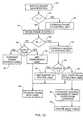
- FIG. 7is a flow chart of the processing steps performed by the router interface illustrated in FIG. 6 when a data frame is transmitted to the router.
- FIG. 8is a flow chart of the processing steps performed by the router interface illustrated in FIG. 6 when a data frame is received from the router.
- FIG. 9is a block-diagram of an output trunk/port interface used in the implementation of the method according to the invention.
- FIG. 10is a flow chart of the processing steps performed by the output trunk/port interface illustrated in FIG. 9 when a data frame has to be transmitted.
- FIG. 1represents a global network providing the interconnection of access devices through an IP network 10 (such as a WAN) including a plurality of switching nodes such as nodes 12 , 14 , 16 and 18 wherein the invention is implemented. Each of these nodes is associated with a router R such as routers 13 , 15 , 17 and 19 respectively associated with nodes 12 , 14 , 16 and 18 , in charge of the routing function.
- IP network 10such as a WAN
- FIG. 1represents a global network providing the interconnection of access devices through an IP network 10 (such as a WAN) including a plurality of switching nodes such as nodes 12 , 14 , 16 and 18 wherein the invention is implemented. Each of these nodes is associated with a router R such as routers 13 , 15 , 17 and 19 respectively associated with nodes 12 , 14 , 16 and 18 , in charge of the routing function.
- peripheral unitssuch as DTE's 20 or 22 or legacy routers 24 , 26 or 27 linked to other networks such as LANs or other WANs are connected to the switching nodes of the network 10 by ports (P), whereas the switching nodes of network 10 are interconnected by trunks (TK).
- Pports
- TKtrunks
- a switching node 28wherein the method of the invention is implemented, is connected to a legacy router 30 by a physical link which is a multiple link allowing to get several virtual independent logical links such as Virtual Circuits (Vc).
- Node 28is an ingress node having two port interfaces 32 and 34 connected respectively to input Link 1 and Link 2 , and two trunk interfaces 36 and 38 connected respectively to output Link 3 and Link 4 .
- the port and trunk interfacesare connected to Switch Engine 40 which is connected to Legacy Router 30 by a Router Interface 42 and performs the switching function. It would be possible to add other routing interfaces and routers for backup, load balancing, extension of the routing capacity, security.
- the router useis defined at the port or trunk level and may be different for each flow.
- switching node illustrated in FIG. 2is an ingress node
- the inventioncould be implemented in an egress node wherein input links are connected to trunk interfaces and output links are connected to port interfaces, or an intermediate node wherein input links as well as output links are connected to trunk interfaces.
- a first frame of a flow of data having a format A arriving on Link 1 of Port Interface 32should be routed as there is not yet switching information available in the switching node.
- Port Interface 32forwards the frame having format C to Router Interface 42 via Switch Engine 40 .
- Router Interface 42encapsulates the frame in Vc 32 which is devoted to all data coming from Port Interface 32 .
- Router 30which receives the frame having format D from Router Interface 42 , performs the routing function and finds the route to the next router. Assuming that the next router is connected by Link 3 , the router defines the path to Link 3 on Vc 36 corresponding to trunk interface 36 .
- the frameis sent from Router 30 to Router Interface 42 with format D on Vc 36 and then to the Trunk Interface 36 through Switch Engine 40 with format C. Finally, the frame is sent on Link 3 with a label that is used to address the next router on this link, while an update of Port Interface as explained hereafter is made to allow switching of all further frames of the same flow from Port Interface 32 directly to Trunk Interface 36 via Switch Engine 40 .
- Port Interfaceas explained hereafter is made to allow switching of all further frames of the same flow from Port Interface 32 directly to Trunk Interface 36 via Switch Engine 40 .
- a switch headerin the format of a frame transported between the different elements of a switching node, as illustrated in FIG. 3 .
- Such a switch headerincludes a source Id which is filled with the identification of the input port (or trunk), a destination Id which is set first to the identification of the router interface by the port/trunk interface and then to the trunk/port interface by the router if the frame belongs to a new flow of data or is set to the output interface if the frame belongs to a known flow of data.
- the label fieldis filled first with a temporary label during the self learning routing phase when the first frame is processed and then with a switching label during the second phase when the following frames are processed.
- the switch headeralso includes three bits:
- Tset to 0 when the input link is connected to a port, and set to 1 when the input link is connect to a trunk
- Rset to 0 when there is no routing to be made and set to 1 when routing is necessary because it is the first frame of a flow of data
- Cis set to 0 for a data frame and set to 1 for a control frame.
- FIG. 4represents an input interface such as port interface 32 (or 34 ) or trunk interface 36 (or 38 ) of FIG. 2, where the data frames are received from an external link
- FIG. 5is a flow chart of the processing steps performed in the input interface.
- the framesare first processed by Low Layer Interface 44 wherein they are extracted (step 60 ) from the lower layers 1 (physical layer) and 2 (e.g. ATM or frame relay).
- the layer 3 protocolis then identified (step 62 ) in Protocol Label Identification Unit 46 .
- some fields of the frame headerare checked to identify the kind of flow to which it belongs. This can be made by looking at the flow identification of the frame (if any) or at various fields including the originating and the destination address. This process involves to look up in an Input Table 48 and allows to determine (step 64 ) whether the data frame belongs to a known flow or to a new flow.
- a switch header having the format illustrated in FIG. 3is then added to the data frame by Input Table 48 which had been previously stored in Buffer 50 by Protocol Identification 46 . Either it is a new flow of data and the added switch header will contain a new free label (step 66 ) used as a temporary label or it is a known flow of data and the added switch header will contain the label found in Input Table 48 by the lookup process (step 68 ), this label being called switching label.
- the data frame with its switch headeris then forwarded via Multiplexer 52 to Switch Engine 40 . The latter transmits the data frame either to router interface (step 70 ) or to the output port/trunk interface (step 72 ), this destination being defined by the destination Id field of the switch header added to the data frame.
- Port interface 32also includes a Table Update unit 54 receiving update messages from Switch Engine 40 , such messages containing a switching label for a flow of data and information about the destination output port/trunk that should be stored in Input Table 48 to identify a new switched flow of data in order to switch the next frames of this flow directly to the output port/trunk.
- Table Update unit 54After decoding of the update message, Table Update unit 54 sends it to Control unit 56 which updates Input Table 48 . Note that further to the input table updating, Control unit 56 also sends a message to Router Interface 42 (see FIG. 2) via Multiplexer 52 and Switch Engine 40 in order to clear the field which was set during an input header buffer as explained hereafter.
- the intermediate switching node or for an egress node wherein the input link is connected to a trunk instead of a portit is not the protocol which is identified (step 62 ) but rather the routing label which has been assigned to the data frame by the preceding switching node (see format B in FIG. 3 ). In such a case, there is no need to determine whether it is a new flow or a known flow as the label used on the input link indicates whether the frame should be routed or switched.
- FIG. 6represents Router Interface 42 of FIG. 2
- FIGS. 7 and 8are flow charts giving the processing steps performed in the Router Interface when the data frame is transferred respectively from the router interface to the router and from the router to the router interface.
- An incoming data frame from Switching Engine 40is first identified (step 100 of FIG. 7) by Header Identification unit 74 in order to check (step 102 ) if the frame is a data frame or a control frame. If it is a data frame, this one is sent to Input Header Buffer 80 wherein the protocol header and the switch header are stored (step 104 ) and to Low Layer Interface 82 to be encapsulated with layers 1 and 2 in the virtual circuit corresponding to the source Id which is available in the switch header. This is made by mapping (step 106 ) the value of the source Id to the corresponding Vc added by Low Layer Interface 82 . At this time, the switch header is removed and the encapsulated frame is sent to Router 30 to be handled as a normal frame (step 108 ).
- Control Unit 76When a control frame is identified, it is forwarded to Control Unit 76 (step 110 ).
- the latteruses the data field of the control frame to perform some actions such as initialization of Match Check Lookup unit 78 to define the checking to be performed, or clearing of the temporary label stored in Input Header Buffer 80 because a flow of data has been assigned. Note that such a clearing of Input Header Buffer is also performed automatically by using a timer. Indeed, the fields corresponding to an output frame that has not been associated with an input frame after a predetermined period of time may be cleared insofar as the input frame may be considered as being retained by the router. Such a predetermined time before clearing an unused frame depends upon the router and network characteristics, but is generally between 10 ms and 100 ms.
- the order of the frames transmitted to the routermay not be the order of the frames received on the router interface from the router.
- some frames sent to the routermay have for destination the router itself and therefore will never be seen at the input of the router interface.
- the routeritself generates some traffic for example to the other routers in the networks, to some servers such as DNS servers or network management servers. So, the incoming frame type on the router interface is unpredictable. Thus, there is a need to identify each incoming frame to classify it by checking whether it corresponds to a frame sent on the output of the router interface or if it is a unknown frame.
- An incoming frame from Router 30 in virtual circuit Vc mis first received by Low Layer Interface 82 .
- the protocol header of the frame and the number Vc on which the frame was receivedare stored (step 112 ) in Routed Header Buffer 84 , and the full frame is stored in Data Buffer 86 (step 114 ).
- a comparison between the protocol header just stored in Routed Header Buffer 34 with protocol headers stored in Input Header Buffer 80is made (step 116 ) by using Match Check Lookup unit 78 . Note that this comparison is generally not made on the full protocol header since some fields may have been changed by the router.
- the fields which may be usefulare the protocol type, the flow Id (if available), the source and destination addresses, upper protocol types, etc.
- the destination Idcorresponds to the Vc value m on which the frame was received.
- the new switch headeris added by Switch Header Adding unit 90 to the data frame which had been stored in Data Buffer 86 (step 124 ) before being transmitted to the destination output trunk/port interface via Multiplexer 92 and Switch Engine 40 (step 126 ).
- FIG. 9representing a block diagram of an output trunk/port interface is now described in combination with FIG. 10 representing a flow chart of the processing steps performed in the trunk/port interface when the data frame is transmitted over the network to the next switching node or to the receiving unit.
- a data frame transferred from Switch Engine 40comes from either a port/trunk interface or from the router interface. Therefore, several processings may be implemented depending upon the contents of the second switch header which is concatenated to the frame and determines whether it is a routed frame, a switched frame, or a control message.
- the switch headeris identified by Switch Header Identification unit 130 (step 142 ).
- the data frame together with the temporary label included in the switch headeris stored in buffer 136 (step 148 ).
- a forwarding label provided by Output Table 134is added to the data frame stored in Buffer 136 by Adding Label unit 138 before being encapsulated with layers 1 and 2 , by Lower Layer Interface 140 and then transmitted (step 158 ) to the next switching node.
- the output interfaceis a port interface meaning that the switching node is an egress node
- the data frameis transmitted without label (step 160 ) directly by Buffer 136 wherein it is stored to the receiving unit.
- a testis made by the latter unit to check whether the value of source Id in the switch header is 0 meaning that the frame has been initiated by the router, or is 1 meaning that the 10 frame comes from an input port/trunk interface (step 162 ).
- a routing labelwhich is of the router to router type is added by Adding Label unit 138 (step 164 ) to the data frame before being encapsulated in Lower Layer Interface 140 and forwarded to the next switching node (step 158 ).
- a routing label which is of a port/trunk to router typeis added by Adding Label unit 138 (step 166 ) to the data frame before being encapsulated in Lower Layer Interface 140 and forwarded to the next switching node (step 158 ).
- Control Unit 132In addition to adding a port/trunk to router label to the data frame, Control Unit 132 has to inform the input port/trunk interface that a switching label has to be associated with the new flow of data. For this, a control message is sent by Control Unit 132 to the input port/trunk interface via Switch Engine 40 (step 168 ).
- This messagecomprises a switch header composed of a Source Id which is the Source Id included in the frame received from the router interface, a Destination Id which corresponds to the source input interface, a Label which is the temporary label included in the switch header received from the router interface in order to identify the flow.
- the messagealso contains an information field telling that it is an input table update message, the current port/trunk Id which was the destination Id of the frame received from the router interface, and the switching label which will be used for switching the next frames of the same flow of data.
- Input Table 48(see FIG. 4) is updated (step 170 ) with necessary information, that is the switching label and the destination Id (current port/trunk Id of the message) associated with the source Id (Destination Id in the switch header of the message).
- Control Unit 132has to be sent at this time by Control Unit 132 to clear the temporary label Input Header Buffer 80 of the router interface as mentioned hereabove in reference to FIG. 6 and FIG. 7 .
- the switching label sent to the input port or trunkmay be either the final forwarding label used for data transmission on the output trunk or may be replaced in the output trunk interface by a forwarding label using a direct mapping in output table 134 . It may be the case if a forwarding label shares several flows having each a different switching label but the same destination. This mechanism is also called label merging.
Landscapes
- Engineering & Computer Science (AREA)
- Computer Networks & Wireless Communication (AREA)
- Signal Processing (AREA)
- Data Exchanges In Wide-Area Networks (AREA)
Abstract
Description
Claims (17)
Applications Claiming Priority (2)
| Application Number | Priority Date | Filing Date | Title |
|---|---|---|---|
| EP99480003 | 1999-02-26 | ||
| EP99480003AEP1032164A1 (en) | 1999-02-26 | 1999-02-26 | Method of self-learning for the switching nodes of a data transmission network |
Publications (1)
| Publication Number | Publication Date |
|---|---|
| US6628655B1true US6628655B1 (en) | 2003-09-30 |
Family
ID=8242422
Family Applications (1)
| Application Number | Title | Priority Date | Filing Date |
|---|---|---|---|
| US09/490,767Expired - Fee RelatedUS6628655B1 (en) | 1999-02-26 | 2000-01-24 | Method of self-learning for the switching nodes of a data transmission network |
Country Status (2)
| Country | Link |
|---|---|
| US (1) | US6628655B1 (en) |
| EP (1) | EP1032164A1 (en) |
Cited By (17)
| Publication number | Priority date | Publication date | Assignee | Title |
|---|---|---|---|---|
| US20020027914A1 (en)* | 2000-09-06 | 2002-03-07 | Masayuki Shinohara | Packet switching equipment and switching control method |
| US6832265B1 (en)* | 2000-01-07 | 2004-12-14 | Cisco Technology, Inc. | Methods and apparatus for moving data elements within a data communications device |
| US20050198351A1 (en)* | 2004-02-20 | 2005-09-08 | Microsoft Corporation | Content-based routing |
| US6980549B1 (en)* | 2000-09-01 | 2005-12-27 | Avaya Technology Corp. | Policy enforcing switch |
| US6980521B1 (en)* | 2000-11-29 | 2005-12-27 | Cisco Technology, Inc. | Method and apparatus for per session load balancing with improved load sharing in a packet switched network |
| US20060047795A1 (en)* | 2004-05-18 | 2006-03-02 | Marconi Communication, Inc. | Service object for network management |
| US7130926B1 (en)* | 2001-03-29 | 2006-10-31 | Nortel Networks Limited | Control plane failure recovery in a network |
| US7136374B1 (en)* | 2001-03-19 | 2006-11-14 | Juniper Networks, Inc. | Transport networks supporting virtual private networks, and configuring such networks |
| US20070171908A1 (en)* | 2006-01-23 | 2007-07-26 | Allied Telesis Holdings K.K. | Method and system for improving traffic distribution across a communication network |
| US20070286185A1 (en)* | 2003-12-22 | 2007-12-13 | Anders Eriksson | Control of Mobile Packet Streams |
| US20080247389A1 (en)* | 2007-04-04 | 2008-10-09 | Qualcomm Incorporated | Signaling in a cluster |
| US20080247311A1 (en)* | 2007-04-03 | 2008-10-09 | Qualcomm Incorporated | Signaling in a cluster |
| US20090133105A1 (en)* | 2005-05-16 | 2009-05-21 | James David Larsen | Multi-medium wide area communication network |
| US7542423B1 (en)* | 2001-03-16 | 2009-06-02 | Cisco Technology, Inc. | Hardware load balancing through a single fabric |
| US20100202464A1 (en)* | 2009-02-10 | 2010-08-12 | Ralink Technology Corporation | Method and apparatus for preloading packet headers and system using the same |
| US20110182194A1 (en)* | 2008-03-28 | 2011-07-28 | British Telecommunications Public Limited Company | Measuring network metrics |
| US20150215196A1 (en)* | 2012-10-22 | 2015-07-30 | Huawei Technologies Co., Ltd. | Packet transmission method and apparatus |
Families Citing this family (2)
| Publication number | Priority date | Publication date | Assignee | Title |
|---|---|---|---|---|
| US7443856B2 (en)* | 2004-01-14 | 2008-10-28 | Lucent Technologies Inc. | Managing processing utilization in a network node |
| WO2012050071A1 (en)* | 2010-10-14 | 2012-04-19 | 日本電気株式会社 | Communication system, control device, method for setting processing rules, and program |
Citations (6)
| Publication number | Priority date | Publication date | Assignee | Title |
|---|---|---|---|---|
| US5717691A (en)* | 1995-10-30 | 1998-02-10 | Nec Usa, Inc. | Multimedia network interface for asynchronous transfer mode communication system |
| US5903559A (en)* | 1996-12-20 | 1999-05-11 | Nec Usa, Inc. | Method for internet protocol switching over fast ATM cell transport |
| US5996021A (en)* | 1997-05-20 | 1999-11-30 | At&T Corp | Internet protocol relay network for directly routing datagram from ingress router to egress router |
| US6151324A (en)* | 1996-06-03 | 2000-11-21 | Cabletron Systems, Inc. | Aggregation of mac data flows through pre-established path between ingress and egress switch to reduce number of number connections |
| US6434156B1 (en)* | 1998-07-24 | 2002-08-13 | Nortel Networks Limited | Virtual switching for interconnected networks |
| US6449251B1 (en)* | 1999-04-02 | 2002-09-10 | Nortel Networks Limited | Packet mapper for dynamic data packet prioritization |
- 1999
- 1999-02-26EPEP99480003Apatent/EP1032164A1/ennot_activeWithdrawn
- 2000
- 2000-01-24USUS09/490,767patent/US6628655B1/ennot_activeExpired - Fee Related
Patent Citations (6)
| Publication number | Priority date | Publication date | Assignee | Title |
|---|---|---|---|---|
| US5717691A (en)* | 1995-10-30 | 1998-02-10 | Nec Usa, Inc. | Multimedia network interface for asynchronous transfer mode communication system |
| US6151324A (en)* | 1996-06-03 | 2000-11-21 | Cabletron Systems, Inc. | Aggregation of mac data flows through pre-established path between ingress and egress switch to reduce number of number connections |
| US5903559A (en)* | 1996-12-20 | 1999-05-11 | Nec Usa, Inc. | Method for internet protocol switching over fast ATM cell transport |
| US5996021A (en)* | 1997-05-20 | 1999-11-30 | At&T Corp | Internet protocol relay network for directly routing datagram from ingress router to egress router |
| US6434156B1 (en)* | 1998-07-24 | 2002-08-13 | Nortel Networks Limited | Virtual switching for interconnected networks |
| US6449251B1 (en)* | 1999-04-02 | 2002-09-10 | Nortel Networks Limited | Packet mapper for dynamic data packet prioritization |
Non-Patent Citations (5)
| Title |
|---|
| Bob Sultan: "A swicth-router taxomony" Computer Communications vol. 21, Mar. 1, 1998, pp. 101-110, XP002112317 UK *the whole Document. |
| Konish S J Rr: "Layer 3 Switching Alternatives" IEEE Military Communications Conference. Proceedings. Milcom 98, vol. 1, 1998, pp. 287-291, XP002111744 New York, USA *the whole document*. |
| Shishir Agrawal, "IP Switching" Online! Retrieved from Internet:<URL: httpL//www.cis.ohio-state.edu/äjain/cis788-97/ip-Switching/index.htm>Aug. 16, 1997 XP002111746 *the whole document*. |
| Shishir Agrawal, "IP Switching" Online! Retrieved from Internet:<URL: httpL//www.cis.ohio-state.edu/{jain/cis788-97/ip-Switching/index.htm>Aug. 16, 1997 XP002111746 *the whole document*. |
| Y. Rekhter, B. Davis, D. Katz, E. Rosen, G. Swallow: Cisco Systems, Inc. "Cisco Systems Tag Switching Architecture Overview" Online! Retrieved from Internet:, URL: ftp://ftp.isi.edu/in-notes/rfc2105.txt. Feb. 1997 Xp002111745 *p. 2-p. 9*. |
Cited By (30)
| Publication number | Priority date | Publication date | Assignee | Title |
|---|---|---|---|---|
| US7395356B2 (en) | 2000-01-07 | 2008-07-01 | Cisco Technology, Inc. | Methods and apparatus for moving data elements within a data communications device |
| US6832265B1 (en)* | 2000-01-07 | 2004-12-14 | Cisco Technology, Inc. | Methods and apparatus for moving data elements within a data communications device |
| US6980549B1 (en)* | 2000-09-01 | 2005-12-27 | Avaya Technology Corp. | Policy enforcing switch |
| US20110199925A1 (en)* | 2000-09-06 | 2011-08-18 | Juniper Networks, Inc. | Packet switching equipment and switching control method |
| US7916724B2 (en) | 2000-09-06 | 2011-03-29 | Juniper Networks, Inc. | Packet switching equipment and switching control method |
| US20100232428A1 (en)* | 2000-09-06 | 2010-09-16 | Juniper Networks, Inc. | Packet switching equipment and switching control method |
| US7751427B2 (en) | 2000-09-06 | 2010-07-06 | Juniper Networks, Inc. | Packet switching equipment and switching control method |
| US20020027914A1 (en)* | 2000-09-06 | 2002-03-07 | Masayuki Shinohara | Packet switching equipment and switching control method |
| US7177309B2 (en)* | 2000-09-06 | 2007-02-13 | Juniper Networks, Inc. | Packet switching equipment and switching control method |
| US20070110045A1 (en)* | 2000-09-06 | 2007-05-17 | Juniper Networks, Inc. | Packet switching equipment and switching control method |
| US7414979B1 (en)* | 2000-11-29 | 2008-08-19 | Cisco Technology, Inc. | Method and apparatus for per session load balancing with improved load sharing in a packet switched network |
| US7233575B1 (en) | 2000-11-29 | 2007-06-19 | Cisco Technology, Inc. | Method and apparatus for per session load balancing with improved load sharing in a packet switched network |
| US6980521B1 (en)* | 2000-11-29 | 2005-12-27 | Cisco Technology, Inc. | Method and apparatus for per session load balancing with improved load sharing in a packet switched network |
| US7542423B1 (en)* | 2001-03-16 | 2009-06-02 | Cisco Technology, Inc. | Hardware load balancing through a single fabric |
| US7136374B1 (en)* | 2001-03-19 | 2006-11-14 | Juniper Networks, Inc. | Transport networks supporting virtual private networks, and configuring such networks |
| US7130926B1 (en)* | 2001-03-29 | 2006-10-31 | Nortel Networks Limited | Control plane failure recovery in a network |
| US20070286185A1 (en)* | 2003-12-22 | 2007-12-13 | Anders Eriksson | Control of Mobile Packet Streams |
| US8155116B2 (en)* | 2003-12-22 | 2012-04-10 | Telefonaktiebolaget Lm Ericsson (Publ) | Control of mobile packet streams |
| US20050198351A1 (en)* | 2004-02-20 | 2005-09-08 | Microsoft Corporation | Content-based routing |
| US20060047795A1 (en)* | 2004-05-18 | 2006-03-02 | Marconi Communication, Inc. | Service object for network management |
| US20090133105A1 (en)* | 2005-05-16 | 2009-05-21 | James David Larsen | Multi-medium wide area communication network |
| US8780899B2 (en)* | 2006-01-23 | 2014-07-15 | Allied Telesis Holdings K.K. | Method and system for improving traffic distribution across a communication network |
| US20070171908A1 (en)* | 2006-01-23 | 2007-07-26 | Allied Telesis Holdings K.K. | Method and system for improving traffic distribution across a communication network |
| US20080247311A1 (en)* | 2007-04-03 | 2008-10-09 | Qualcomm Incorporated | Signaling in a cluster |
| US8638668B2 (en)* | 2007-04-03 | 2014-01-28 | Qualcomm Incorporated | Signaling in a cluster |
| US20080247389A1 (en)* | 2007-04-04 | 2008-10-09 | Qualcomm Incorporated | Signaling in a cluster |
| US8363551B2 (en)* | 2008-03-28 | 2013-01-29 | British Telecommunications Public Limited Company | Measuring network metrics |
| US20110182194A1 (en)* | 2008-03-28 | 2011-07-28 | British Telecommunications Public Limited Company | Measuring network metrics |
| US20100202464A1 (en)* | 2009-02-10 | 2010-08-12 | Ralink Technology Corporation | Method and apparatus for preloading packet headers and system using the same |
| US20150215196A1 (en)* | 2012-10-22 | 2015-07-30 | Huawei Technologies Co., Ltd. | Packet transmission method and apparatus |
Also Published As
| Publication number | Publication date |
|---|---|
| EP1032164A1 (en) | 2000-08-30 |
Similar Documents
| Publication | Publication Date | Title |
|---|---|---|
| US6628655B1 (en) | Method of self-learning for the switching nodes of a data transmission network | |
| US6963585B1 (en) | Method and system for establishing a virtual path capability in a frame relay network | |
| US5394402A (en) | Hub for segmented virtual local area network with shared media access | |
| US7401157B2 (en) | Combining separate infiniband subnets into virtual subnets | |
| US7787466B1 (en) | Nexthop to a forwarding table | |
| US7221676B2 (en) | Supporting local IB packet communication between separate subnets | |
| US9106506B2 (en) | Filter-based forwarding in a network | |
| US7307996B2 (en) | Infiniband router having an internal subnet architecture | |
| JP3842303B2 (en) | System and method for multilayer network elements | |
| US6934260B1 (en) | Arrangement for controlling learning of layer 3 network addresses in a network switch | |
| US7242665B2 (en) | Network device virtual interface | |
| JP4076586B2 (en) | Systems and methods for multilayer network elements | |
| US5999541A (en) | Transmission of token-ring packets over ethernet by tunneling | |
| US6389023B1 (en) | Router device and frame transfer method using datalink layer frame switching | |
| US20010049739A1 (en) | Apparatus and method for interworking between MPLS network and non-MPLS network | |
| EP1158725A2 (en) | Method and apparatus for multi- redundant router protocol support | |
| US20060126644A1 (en) | VPN router and VPN identification method by using logical channel identifiers | |
| US20020006112A1 (en) | Method and system for modeling and advertising asymmetric topology of a node in a transport network | |
| US7058730B2 (en) | Unique address space and method for a transport network | |
| US8295202B2 (en) | Dynamic connectivity determination | |
| EP1863230B1 (en) | A method for implementing on-ring process, off-ring process and data forwarding in resilience packet data ringnet and a network device thereof | |
| US7184403B1 (en) | Hardware load balancing through a single fabric | |
| CN113285878A (en) | Load sharing method and first network device | |
| Cisco | Transparent Bridging Commands | |
| Cisco | Transparent Bridging Commands |
Legal Events
| Date | Code | Title | Description |
|---|---|---|---|
| AS | Assignment | Owner name:INTERNATIONAL BUSINESS MACHINES CORPORATION, NEW Y Free format text:ASSIGNMENT OF ASSIGNORS INTEREST;ASSIGNORS:FIESCHI, JACQUES;CLAUDE GALAND;LE PENNEC, JEAN-FRANCOIS;AND OTHERS;REEL/FRAME:010546/0525;SIGNING DATES FROM 20000106 TO 20000107 | |
| FEPP | Fee payment procedure | Free format text:PAYOR NUMBER ASSIGNED (ORIGINAL EVENT CODE: ASPN); ENTITY STATUS OF PATENT OWNER: LARGE ENTITY | |
| FPAY | Fee payment | Year of fee payment:4 | |
| REMI | Maintenance fee reminder mailed | ||
| FPAY | Fee payment | Year of fee payment:8 | |
| SULP | Surcharge for late payment | Year of fee payment:7 | |
| AS | Assignment | Owner name:GOOGLE INC., CALIFORNIA Free format text:ASSIGNMENT OF ASSIGNORS INTEREST;ASSIGNOR:INTERNATIONAL BUSINESS MACHINES CORPORATION;REEL/FRAME:026894/0001 Effective date:20110817 | |
| REMI | Maintenance fee reminder mailed | ||
| LAPS | Lapse for failure to pay maintenance fees | ||
| STCH | Information on status: patent discontinuation | Free format text:PATENT EXPIRED DUE TO NONPAYMENT OF MAINTENANCE FEES UNDER 37 CFR 1.362 | |
| FP | Lapsed due to failure to pay maintenance fee | Effective date:20150930 | |
| AS | Assignment | Owner name:GOOGLE LLC, CALIFORNIA Free format text:CHANGE OF NAME;ASSIGNOR:GOOGLE INC.;REEL/FRAME:044144/0001 Effective date:20170929 | |
| AS | Assignment | Owner name:GOOGLE LLC, CALIFORNIA Free format text:CORRECTIVE ASSIGNMENT TO CORRECT THE THE REMOVAL OF THE INCORRECTLY RECORDED APPLICATION NUMBERS 14/149802 AND 15/419313 PREVIOUSLY RECORDED AT REEL: 44144 FRAME: 1. ASSIGNOR(S) HEREBY CONFIRMS THE CHANGE OF NAME;ASSIGNOR:GOOGLE INC.;REEL/FRAME:068092/0502 Effective date:20170929 |