US6628505B1 - Flow-through capacitor, system and method - Google Patents
Flow-through capacitor, system and methodDownload PDFInfo
- Publication number
- US6628505B1 US6628505B1US10/049,872US4987202AUS6628505B1US 6628505 B1US6628505 B1US 6628505B1US 4987202 AUS4987202 AUS 4987202AUS 6628505 B1US6628505 B1US 6628505B1
- Authority
- US
- United States
- Prior art keywords
- capacitor
- flow
- fluid
- cells
- cell
- Prior art date
- Legal status (The legal status is an assumption and is not a legal conclusion. Google has not performed a legal analysis and makes no representation as to the accuracy of the status listed.)
- Expired - Fee Related
Links
Images


Classifications
- C—CHEMISTRY; METALLURGY
- C02—TREATMENT OF WATER, WASTE WATER, SEWAGE, OR SLUDGE
- C02F—TREATMENT OF WATER, WASTE WATER, SEWAGE, OR SLUDGE
- C02F1/00—Treatment of water, waste water, or sewage
- C02F1/46—Treatment of water, waste water, or sewage by electrochemical methods
- C02F1/469—Treatment of water, waste water, or sewage by electrochemical methods by electrochemical separation, e.g. by electro-osmosis, electrodialysis, electrophoresis
- C02F1/4691—Capacitive deionisation
- C—CHEMISTRY; METALLURGY
- C02—TREATMENT OF WATER, WASTE WATER, SEWAGE, OR SLUDGE
- C02F—TREATMENT OF WATER, WASTE WATER, SEWAGE, OR SLUDGE
- C02F1/00—Treatment of water, waste water, or sewage
- C02F1/46—Treatment of water, waste water, or sewage by electrochemical methods
- C02F1/461—Treatment of water, waste water, or sewage by electrochemical methods by electrolysis
- C02F1/46104—Devices therefor; Their operating or servicing
- C—CHEMISTRY; METALLURGY
- C02—TREATMENT OF WATER, WASTE WATER, SEWAGE, OR SLUDGE
- C02F—TREATMENT OF WATER, WASTE WATER, SEWAGE, OR SLUDGE
- C02F2103/00—Nature of the water, waste water, sewage or sludge to be treated
- C02F2103/16—Nature of the water, waste water, sewage or sludge to be treated from metallurgical processes, i.e. from the production, refining or treatment of metals, e.g. galvanic wastes
- C—CHEMISTRY; METALLURGY
- C02—TREATMENT OF WATER, WASTE WATER, SEWAGE, OR SLUDGE
- C02F—TREATMENT OF WATER, WASTE WATER, SEWAGE, OR SLUDGE
- C02F2103/00—Nature of the water, waste water, sewage or sludge to be treated
- C02F2103/34—Nature of the water, waste water, sewage or sludge to be treated from industrial activities not provided for in groups C02F2103/12 - C02F2103/32
- C02F2103/346—Nature of the water, waste water, sewage or sludge to be treated from industrial activities not provided for in groups C02F2103/12 - C02F2103/32 from semiconductor processing, e.g. waste water from polishing of wafers
- C—CHEMISTRY; METALLURGY
- C02—TREATMENT OF WATER, WASTE WATER, SEWAGE, OR SLUDGE
- C02F—TREATMENT OF WATER, WASTE WATER, SEWAGE, OR SLUDGE
- C02F2201/00—Apparatus for treatment of water, waste water or sewage
- C02F2201/46—Apparatus for electrochemical processes
- C02F2201/461—Electrolysis apparatus
- C02F2201/46105—Details relating to the electrolytic devices
- C02F2201/4612—Controlling or monitoring
- C02F2201/46125—Electrical variables
- C02F2201/4613—Inversing polarity
- C—CHEMISTRY; METALLURGY
- C02—TREATMENT OF WATER, WASTE WATER, SEWAGE, OR SLUDGE
- C02F—TREATMENT OF WATER, WASTE WATER, SEWAGE, OR SLUDGE
- C02F2209/00—Controlling or monitoring parameters in water treatment
- C02F2209/05—Conductivity or salinity
Definitions
- a cellcomprises at least one anode and cathode layer with an ionically conducting electrolyte that operates within the rated cell voltage.
- This rated voltageis usually set below the level where electrode deterioration takes place or other undesirable electrochemical reactions occur. Where multiple electrode layers exist, these layers are usually connected in parallel.
- this electrolyteis the working fluid that is being treated. In order not to exceed the rated voltage per cell, this fluid must be electrically isolated from the fluid in any other cell.
- individual flow-through capacitor cartridge holdersmust be chained together.
- FIG. 15 of Andelman U.S. Pat. No. 5,799,891pictures a flow-through capacitor system with three flow-through capacitors in individual cartridge holders.
- Each cartridge holdercontains one cell, typically made from multiple, parallel-connected electrodes.
- Use of an additional cartridge holder per cellincreases the cost of series-connected, flow-through capacitors that comprise multiple cells, yet are self-contained in one cartridge holder.
- Otowautilizes single electrode layers sealed by a gasket.
- Otowadoes not use double-sided electrodes to provide a capacitor of enhanced voltage internal to a single cartridge holder.
- Farmerutilizes gaskets and many double-sided, internal electrode layers, but these layers are connected in parallel.
- the inventionrelates to a flow-through capacitor, system and method.
- the inventionis also related to a series-connected, flow-through capacitor with multiple individual electrolyte-isolated cells and which capacitor is self-contained in a single cartridge holder.
- An additional advantage of the present inventionis that only the electrical leads at the either end of the electrode stack need be connected to a power supply, yet voltage may be higher than the single cell rating.
- the inventioncomprises a flow-through capacitor for the purification of an electrolyte fluid, which capacitor includes: a cartridge holder; an inlet in the holder for a fluid to be purified; an outlet in the holder for the withdrawal of a purified fluid; a discharge outlet; and a plurality of electrolyte-isolated individual cells, each cell composed of an anode-cathode pair of electrode material in a stacked arrangement within the holder, and the individual cells are electrically connected in series.
- the electrodes of the capacitorare series-connected, due to sealing gasket, so that the intermediate electrodes of the capacitor simultaneously comprise an anode on one side and a cathode on an other side.
- FIG. 1is an exploded perspective view of the electrode layers and gaskets of the invention to form series-connected cells
- FIG. 2shows top plan and side views of individual electrodes and current collectors
- FIG. 3schematically illustrates a charged capacitor of the invention with individual cells
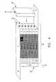
- FIG. 4is a schematic, perspective sectional view of a flow-through capacitor stack of the invention.
- FIG. 5is a schematic illustration of a flow-through capacitor system of the invention.
- FIG. 6is an illustrative perspective sectional view of a flow-through capacitor of the invention with an illustrated plan view of an electrode, spacer, or current collector shape.
- FIG. 1shows the arrangement of layers and gaskets used to isolate the electrodes, in order to utilize both sides of the electrodes 1 , yet form cells with single facing anode and cathode layers per cell.
- the end electrodesare single-sided and may be exposed to the air to form the top fluid seal of the cartridge holder.
- This method of constructionallows the electrical isolation of individual cells by using the electrode or optional current collector in combination with gaskets 2 to form a fluid-tight compartment, whereby the electrolyte from each cell is electrically isolated from the neighboring cells. End electrodes may be drawn out into a lead 3 .
- Gaskets 2may have an optional nonelectrical conductive, but ionically-conductive spacer layer 4 .
- Gasketsmay have flow holes 5 .
- FIG. 2shows the individual electrodes 1 and the optional current collectors 6 .
- FIG. 3shows individual cells 7 formed electrostatically when the capacitor is charged. Gaskets 2 seal against the optional current collector 6 or directly to the conductive material used for electrodes 1 .
- the end electrodes 1are single-sided, and the internal electrodes 1 are double-sided. However, from the electrical point of view of each, all the electrodes 1 are single-sided, providing only one anode and one cathode layer per each individual electrical cell. In the prior art, double-sided electrodes were either an anode or cathode, but not an anode on one side and a cathode on the other side, as in the present invention.
- Each electrode 1may be represented by multiple parallel electrodes, in order to provide thicker cells with better flow properties, yet while maintaining a capacitor that operates at enhanced voltage within a single capacitor cartridge holder.
- the cartridge holderis formed by the gaskets or may be an additional holder into which with gasket assembly of FIG. 3 fits.
- Conductive materialmay be a high surface area conductor greater than 1000 grams per square meter B.E.T. or a high specific capacitance, yet low surface area material, e.g., 10 to 1000 grams per square meter B.E.T. or may be any conductive material, such as titanium, tantalum, and graphite coated with ruthenium oxide or ruthenium oxide, fluorocarbon fiber sheet material, without regard to surface area when used, for example, to remove contaminants via electroplating instead of electrostatic absorption.
- Enhanced voltage through connection in seriesalso aids in energy recovery by allowing the use of more energy efficient, higher voltage DC to DC converts.
- two capacitorsare operated in tandem. One charges with electricity and purifies the solution and the other discharges while it desorbs a concentrated waste. When a flow-through capacitor is ready to be regenerated, it is electrically discharged. This energy can be recovered and used to charge another capacitor during its charge/purification cycle. In order to do this, the voltage of the discharging cell must be increased, so that it may be sufficiently high to charge the purifying capacitor. This may be done with DC to DC converters. These may use, for example, inductor coils or transformers, in order to increase and regulate the voltage. Use of DC to DC converters may also be used in any flow-through capacitor, either parallel, individual cells connected in series or the series design of the present invention.
- FIG. 4shows an assembled capacitor stack 8 , cut lengthwise down the middle, comprised of six cells.
- the flow-through capacitor of the inventionmay be comprised of any number of cells, but from a practical standpoint, is usually less than two hundred cells.
- Each individual cellhas to be similar in size in order to balance the voltage. Flow rates and amounts of material purified should match between each cell as much as possible and in order to keep the voltage balanced between the cells.
- Flowshown by an arrow, is through inlet 9 , into fluid flow baffle 10 , through individual gasket holes 5 and out baffle 10 and exit 11 (hole not shown). Gaskets 2 seal each individual cell 7 , so that an electrically conductive path does not form between cells 7 through the electrolyte represented by the working solution.
- baffle 10The purpose of baffle 10 is to distribute flow between each cell, yet provides a long conductive path length through the electrolyte between the cells. This long path through the electrolyte between cells 7 , holes 5 , and electrical path in baffles 10 has a high resistance and serves to electrically isolate the individual cells 7 .
- Baffle 10may contain a serpentine flow path or other means, in order to lengthen the flow path between cells, so that the resistance is low enough to prevent significant current flow between cells. Generally, this flow path should be long enough and thin enough, so that the electrical resistance is more than 1 ohm and preferably, more than 100 ohms.
- FIG. 5is a flow-though capacitor system of the invention with power supply 27 connected via wires 12 to capacitor stack 8 via screw 13 , nut and bolt assembly 14 , and extending leads 3 .
- wiresmay be welded, if appropriate, for the particular material involved.
- Pump 15 controlled by logic means 16pumps the working fluid to be treated or purified through inlet pipe 17 and out concentrated waste product pipe 18 , which is connected to three-way valve 19 , controlled by combination valve controller, electronic logic means 16 to control the operation of the system and electric conductivity sensor 20 to monitor ionic concentration of the purified liquid, which also controls outlet valve 21 .
- Bladder tank 22serves to store the purified solution and maintain pressurization.
- FIG. 6shows a central flow design capacitor. It is understood that any design which allows an equal fluid flow between cells, yet isolates individual cell compartments, may be used to make an enhanced voltage series, flow-through capacitor.
- FIG. 6shows a design with a central flow path.
- Capacitor stack 8is placed inside cartridge holder 23 . Fluid flow is in through one of the inlets/outlets 24 and out the other one. Flow may be from the side, around the capacitor stack 8 , through the holes 5 , in gaskets 2 , alongside electrode layers 1 , and out central flow path 25 .
- the central flow path 25is formed by central holes in the electrode, optional current collector 6 and spacer layer 4 (not shown).
- the end single-sided electrode 1is extended to form an anode or cathode lead 3 on each side.
- Screw 13extends through cartridge holder 23 to form an electrical connection and leak-proof seal with lead 3 , by washer and screw means 14 .
- Baffle means 10may be inserted into the central flow path 25 , in order to provide a long, thin cross-sectional flow path to isolate cells 7 with a high resistance electrical connection between cells 7 .
- a spiral flow path bafflethat forces fluid to spiral flow into the center of the tube will provide such a flow path. Air bubbles or air gaps will also serve to isolate individual cells, yet allow fluid to flow and distribute evenly between cells.
- Wastewater from a semiconductor plantis neutralized and fed into a 10 cell capacitor stack of the invention at a rate of 1 gallon per minute.
- the capacitoris made from ruthenium-coated, tantalum-conductive, ceramic electrodes connected to a 10 volt power supply. These electrodes are integral to the current collector, so they do not need an additional current collector.
- the capacitoris initially charged at 4 volts for the first minute, then at 10 volts after 1 minute. Corn syrup purified from ash is collected in a collection tank. During regeneration, the electrodes are short-circuited in order to desorb the concentrated waste into the water, which is disposed of down the drain.
- a 20 cell, flow-through capacitor made from 20 cells of activated carbon cloth and graphite foil current collectoris used to purify whey at 1 gallon per minute, connected to a 40 volt power supply. Desalted whey is collected in a container. During regeneration, the whey is replaced with water, and the electrodes are short-circuited in order to desorb the concentrated waste into the water, which is disposed of down the drain.
- a 5 cell, flow-through capacitor made from aligned nanotubesis used to purify sulfate from well water at 2 volts.
- the voltage per cellis 0.4 volts.
- a 100 cell, electrode stack made from copper foilis used to purify plating waste containing 20 ppm nickel metal.
- the stackis run at 20 volts or 0.2 volts per cell.
- Nickel metal plates onto the stackallow purified water to pass through.
- the electrodes in this capacitorare fairly stiff and do not require any spacer to prevent short-circuiting beyond the gasket material. After repeated uses, the old electrodes are replaced and sent to a smelter for recovery.
- the capacitor of Example 4is manufactured with activated carbon cloth electrodes. Instead of replacing the electrodes, they are acid-washed in order to recover the metal in a concentrated acid solution. The cleaned electrodes may then be used in another purification cycle. Polarity is reversed every charge cycle, in order to help keep the electrodes clean.
Landscapes
- Chemical & Material Sciences (AREA)
- Chemical Kinetics & Catalysis (AREA)
- Life Sciences & Earth Sciences (AREA)
- Electrochemistry (AREA)
- Analytical Chemistry (AREA)
- Molecular Biology (AREA)
- Health & Medical Sciences (AREA)
- General Chemical & Material Sciences (AREA)
- Hydrology & Water Resources (AREA)
- Engineering & Computer Science (AREA)
- Environmental & Geological Engineering (AREA)
- Water Supply & Treatment (AREA)
- Organic Chemistry (AREA)
- Electric Double-Layer Capacitors Or The Like (AREA)
Abstract
Description
Claims (27)
Priority Applications (1)
| Application Number | Priority Date | Filing Date | Title |
|---|---|---|---|
| US10/049,872US6628505B1 (en) | 2000-07-29 | 2000-07-29 | Flow-through capacitor, system and method |
Applications Claiming Priority (2)
| Application Number | Priority Date | Filing Date | Title |
|---|---|---|---|
| US10/049,872US6628505B1 (en) | 2000-07-29 | 2000-07-29 | Flow-through capacitor, system and method |
| PCT/US2000/020768WO2001013389A1 (en) | 1999-08-13 | 2000-07-29 | Flow-through capacitor, system and method |
Publications (1)
| Publication Number | Publication Date |
|---|---|
| US6628505B1true US6628505B1 (en) | 2003-09-30 |
Family
ID=28452172
Family Applications (1)
| Application Number | Title | Priority Date | Filing Date |
|---|---|---|---|
| US10/049,872Expired - Fee RelatedUS6628505B1 (en) | 2000-07-29 | 2000-07-29 | Flow-through capacitor, system and method |
Country Status (1)
| Country | Link |
|---|---|
| US (1) | US6628505B1 (en) |
Cited By (43)
| Publication number | Priority date | Publication date | Assignee | Title |
|---|---|---|---|---|
| US20040019268A1 (en)* | 2000-11-03 | 2004-01-29 | Cardiac Pacemakers, Inc. | Configurations and methods for making capacitor connections |
| US20040130851A1 (en)* | 2002-10-25 | 2004-07-08 | Faris Sadeg M. | Fluid deionization system |
| US20040147961A1 (en)* | 2000-11-03 | 2004-07-29 | Cardiac Pacemakers, Inc. | Flat capacitor for an implantable medical device |
| US6781817B2 (en) | 2000-10-02 | 2004-08-24 | Biosource, Inc. | Fringe-field capacitor electrode for electrochemical device |
| US20040173835A1 (en)* | 2000-11-03 | 2004-09-09 | Cardiac Pacemakers, Inc. | Method for interconnecting anodes and cathodes in a flat capacitor |
| US20040174657A1 (en)* | 2001-04-18 | 2004-09-09 | Andelman Marc D. | Charge barrier flow-through capacitor |
| US20040215281A1 (en)* | 2000-11-03 | 2004-10-28 | Cardiac Pacemakers, Inc. | Capacitor having a feedthrough assembly with a coupling member |
| US20040242734A1 (en)* | 2001-12-21 | 2004-12-02 | Lakeman Pascal E R E J | Additive for rendering inert acidic or halogen-containing compounds contained in olefin polymers |
| US6831825B1 (en)* | 2003-06-10 | 2004-12-14 | Mcwhorter Edward Milton | Fuel cell ionic capacitor |
| US20050011409A1 (en)* | 2001-12-25 | 2005-01-20 | Yasuhide Isobe | Inorganic oxide |
| US6985351B2 (en) | 2000-11-03 | 2006-01-10 | Cardiac Pacemakers, Inc. | Implantable heart monitors having flat capacitors with curved profiles |
| US20060018083A1 (en)* | 2004-07-16 | 2006-01-26 | Schmidt Brian L | Plug for sealing a capacitor fill port |
| US20060049105A1 (en)* | 2004-09-07 | 2006-03-09 | Marine Desalination Systems, L.L.C. | Segregated flow, continuous flow deionization |
| WO2006079417A1 (en) | 2005-01-27 | 2006-08-03 | Unilever N.V. | Water softening device and method |
| US7154739B2 (en) | 2000-11-03 | 2006-12-26 | Cardiac Pacemakers, Inc. | Flat capacitor having an active case |
| US7190569B2 (en) | 2000-11-03 | 2007-03-13 | Cardiac Pacemakers, Inc. | Implantable heart monitors having capacitors with endcap headers |
| US20070097600A1 (en)* | 2004-07-16 | 2007-05-03 | Cardiac Pacemakers, Inc. | Method and apparatus for openings in a capacitor case |
| US20070158185A1 (en)* | 2003-08-06 | 2007-07-12 | Biosource, Incorporated | Power efficient flow through capacitor system |
| US7347880B2 (en) | 2000-11-03 | 2008-03-25 | Cardiac Pacemakers, Inc. | Flat capacitor having staked foils and edge-connected connection members |
| US7368191B2 (en) | 2001-07-25 | 2008-05-06 | Biosource, Inc. | Electrode array for use in electrochemical cells |
| US7408762B2 (en)* | 2004-07-16 | 2008-08-05 | Cardiac Pacemakers, Inc. | Method and apparatus for providing capacitor feedthrough |
| US7456077B2 (en) | 2000-11-03 | 2008-11-25 | Cardiac Pacemakers, Inc. | Method for interconnecting anodes and cathodes in a flat capacitor |
| US7479349B2 (en) | 2002-12-31 | 2009-01-20 | Cardiac Pacemakers, Inc. | Batteries including a flat plate design |
| US20100020473A1 (en)* | 2008-07-28 | 2010-01-28 | Prymak John D | Substrate with embedded patterned capacitance |
| US20100065438A1 (en)* | 2008-09-15 | 2010-03-18 | Sullivan James P | Method of Operating A Capacitive Deionization Cell Using Gentle Charge |
| US20100065511A1 (en)* | 2008-09-15 | 2010-03-18 | Knapp Sean | Method of Regenerating A Capacitive Deionization Cell |
| US20100065439A1 (en)* | 2008-09-15 | 2010-03-18 | Sullivan James P | Method of Operating a Capacitive Deionization Cell Using a Relatively Slow Discharge Flow Rate |
| EP2692698A1 (en)* | 2012-08-02 | 2014-02-05 | Voltea B.V. | A method and an apparatus to remove ions |
| US8671985B2 (en) | 2011-10-27 | 2014-03-18 | Pentair Residential Filtration, Llc | Control valve assembly |
| US8691418B2 (en) | 2003-02-07 | 2014-04-08 | Cardiac Pacemakers, Inc. | Insulative member on battery cathode |
| US20140238862A1 (en)* | 2011-10-14 | 2014-08-28 | Voltea B.V. | Apparatus and method for removal of ions |
| WO2014171383A1 (en)* | 2013-04-15 | 2014-10-23 | 有限会社ターナープロセス | Device and method for reducing ion concentration in aqueous liquid held in system, and apparatus equipped with said device |
| US8961770B2 (en) | 2011-10-27 | 2015-02-24 | Pentair Residential Filtration, Llc | Controller and method of operation of a capacitive deionization system |
| US9010361B2 (en) | 2011-10-27 | 2015-04-21 | Pentair Residential Filtration, Llc | Control valve assembly |
| US9093683B2 (en) | 2002-12-31 | 2015-07-28 | Cardiac Pacemakers, Inc. | Method and apparatus for porous insulative film for insulating energy source layers |
| US9193612B2 (en) | 2009-09-08 | 2015-11-24 | Patrick Michael Curran | Concentric layer electric double layer capacitor cylinder, system, and method of use |
| EP3037389A1 (en) | 2014-12-24 | 2016-06-29 | IDROPAN DELL'ORTO DEPURATORI S.r.l. | Apparatus for purifying a fluid and method for the attainment thereof |
| US9633798B2 (en) | 2013-05-24 | 2017-04-25 | Atlantis Technologies | Atomic capacitor |
| US9637397B2 (en) | 2011-10-27 | 2017-05-02 | Pentair Residential Filtration, Llc | Ion removal using a capacitive deionization system |
| US9695070B2 (en) | 2011-10-27 | 2017-07-04 | Pentair Residential Filtration, Llc | Regeneration of a capacitive deionization system |
| US9859066B2 (en) | 2013-05-24 | 2018-01-02 | Atlantis Technologies | Atomic capacitor |
| US10787378B2 (en) | 2018-05-30 | 2020-09-29 | Atlantis Technologies | Spirally wound electric double layer capacitor device and associated methods |
| JP7374393B1 (en)* | 2023-03-02 | 2023-11-06 | 三菱電機株式会社 | Ion removal device |
Citations (23)
| Publication number | Priority date | Publication date | Assignee | Title |
|---|---|---|---|---|
| US3658674A (en) | 1966-02-28 | 1972-04-25 | Standard Oil Co Ohio | Process for demineralization of water |
| US5192432A (en) | 1990-04-23 | 1993-03-09 | Andelman Marc D | Flow-through capacitor |
| US5196115A (en) | 1990-04-23 | 1993-03-23 | Andelman Marc D | Controlled charge chromatography system |
| US5200068A (en) | 1990-04-23 | 1993-04-06 | Andelman Marc D | Controlled charge chromatography system |
| US5360540A (en) | 1990-04-23 | 1994-11-01 | Andelman Marc D | Chromatography system |
| US5415768A (en) | 1990-04-23 | 1995-05-16 | Andelman; Marc D. | Flow-through capacitor |
| US5425858A (en) | 1994-05-20 | 1995-06-20 | The Regents Of The University Of California | Method and apparatus for capacitive deionization, electrochemical purification, and regeneration of electrodes |
| US5538611A (en) | 1993-05-17 | 1996-07-23 | Marc D. Andelman | Planar, flow-through, electric, double-layer capacitor and a method of treating liquids with the capacitor |
| US5620597A (en) | 1990-04-23 | 1997-04-15 | Andelman; Marc D. | Non-fouling flow-through capacitor |
| US5636437A (en) | 1995-05-12 | 1997-06-10 | Regents Of The University Of California | Fabricating solid carbon porous electrodes from powders |
| WO1998011767A1 (en) | 1996-09-16 | 1998-03-19 | Abb Power T & D Company Inc. | Solid state switching device arrangement for silicon transfer switch |
| US5793603A (en) | 1996-11-19 | 1998-08-11 | Boundless Corp. | Ultracapacitor design having a honey comb structure |
| US5925230A (en) | 1997-10-06 | 1999-07-20 | Southeastern Trading, Llp | Deionization apparatus having non-sacrificial electrodes of different types |
| US5980718A (en) | 1998-05-04 | 1999-11-09 | The Regents Of The University Of California | Means for limiting and ameliorating electrode shorting |
| US6096179A (en) | 1997-10-06 | 2000-08-01 | Southeastern Trading, Llp | Carbon-reinforced electrode and method of making same |
| US6309532B1 (en) | 1994-05-20 | 2001-10-30 | Regents Of The University Of California | Method and apparatus for capacitive deionization and electrochemical purification and regeneration of electrodes |
| WO2001089656A1 (en) | 2000-05-22 | 2001-11-29 | Abb Power T & D Company Inc. | Capacitive deionization cell power supply |
| WO2001090444A1 (en) | 2000-05-22 | 2001-11-29 | Abb Power T & D Company Inc. | Integrated electrode for electrolytic capacitor applications |
| WO2001090443A1 (en) | 2000-05-22 | 2001-11-29 | Abb Power T & D Company Inc. | Capacitive deionization cell structure for control of electrolysis |
| WO2001089671A1 (en) | 2000-05-22 | 2001-11-29 | Abb Power T & D Company Inc. | Capacitive deionization cell structure with voltage distribution control |
| WO2001096245A1 (en) | 2000-06-16 | 2001-12-20 | Capacitive Deionization Technology Systems, Inc. | Capacitive deionization device |
| US6346187B1 (en) | 1999-01-21 | 2002-02-12 | The Regents Of The University Of California | Alternating-polarity operation for complete regeneration of electrochemical deionization system |
| US20020017463A1 (en) | 2000-06-05 | 2002-02-14 | Merida-Donis Walter Roberto | Method and apparatus for integrated water deionization, electrolytic hydrogen production, and electrochemical power generation |
- 2000
- 2000-07-29USUS10/049,872patent/US6628505B1/ennot_activeExpired - Fee Related
Patent Citations (29)
| Publication number | Priority date | Publication date | Assignee | Title |
|---|---|---|---|---|
| US3658674A (en) | 1966-02-28 | 1972-04-25 | Standard Oil Co Ohio | Process for demineralization of water |
| US5748437A (en) | 1990-04-23 | 1998-05-05 | Andelman; Marc D. | Fluid separation system with flow-through capacitor |
| US5192432A (en) | 1990-04-23 | 1993-03-09 | Andelman Marc D | Flow-through capacitor |
| US5196115A (en) | 1990-04-23 | 1993-03-23 | Andelman Marc D | Controlled charge chromatography system |
| US5200068A (en) | 1990-04-23 | 1993-04-06 | Andelman Marc D | Controlled charge chromatography system |
| US5360540A (en) | 1990-04-23 | 1994-11-01 | Andelman Marc D | Chromatography system |
| US5415768A (en) | 1990-04-23 | 1995-05-16 | Andelman; Marc D. | Flow-through capacitor |
| US5547581A (en) | 1990-04-23 | 1996-08-20 | Andelman; Marc D. | Method of separating ionic fluids with a flow through capacitor |
| US5620597A (en) | 1990-04-23 | 1997-04-15 | Andelman; Marc D. | Non-fouling flow-through capacitor |
| US5779891A (en)* | 1990-04-23 | 1998-07-14 | Andelman; Marc D. | Non-fouling flow through capacitor system |
| US5538611A (en) | 1993-05-17 | 1996-07-23 | Marc D. Andelman | Planar, flow-through, electric, double-layer capacitor and a method of treating liquids with the capacitor |
| US6309532B1 (en) | 1994-05-20 | 2001-10-30 | Regents Of The University Of California | Method and apparatus for capacitive deionization and electrochemical purification and regeneration of electrodes |
| US5425858A (en) | 1994-05-20 | 1995-06-20 | The Regents Of The University Of California | Method and apparatus for capacitive deionization, electrochemical purification, and regeneration of electrodes |
| US5954937A (en) | 1994-05-20 | 1999-09-21 | The Regents Of The University Of California | Method and apparatus for capacitive deionization and electrochemical purification and regeneration of electrodes |
| US5636437A (en) | 1995-05-12 | 1997-06-10 | Regents Of The University Of California | Fabricating solid carbon porous electrodes from powders |
| WO1998011767A1 (en) | 1996-09-16 | 1998-03-19 | Abb Power T & D Company Inc. | Solid state switching device arrangement for silicon transfer switch |
| US5793603A (en) | 1996-11-19 | 1998-08-11 | Boundless Corp. | Ultracapacitor design having a honey comb structure |
| US6096179A (en) | 1997-10-06 | 2000-08-01 | Southeastern Trading, Llp | Carbon-reinforced electrode and method of making same |
| US6045685A (en) | 1997-10-06 | 2000-04-04 | Sotheastern Trading, Llp | Method of reducing an ion concentration in a liquid |
| US5977015A (en) | 1997-10-06 | 1999-11-02 | Southeastern Trading Llp | Method for making a carbon-reinforced electrode |
| US5925230A (en) | 1997-10-06 | 1999-07-20 | Southeastern Trading, Llp | Deionization apparatus having non-sacrificial electrodes of different types |
| US5980718A (en) | 1998-05-04 | 1999-11-09 | The Regents Of The University Of California | Means for limiting and ameliorating electrode shorting |
| US6346187B1 (en) | 1999-01-21 | 2002-02-12 | The Regents Of The University Of California | Alternating-polarity operation for complete regeneration of electrochemical deionization system |
| WO2001089656A1 (en) | 2000-05-22 | 2001-11-29 | Abb Power T & D Company Inc. | Capacitive deionization cell power supply |
| WO2001090444A1 (en) | 2000-05-22 | 2001-11-29 | Abb Power T & D Company Inc. | Integrated electrode for electrolytic capacitor applications |
| WO2001090443A1 (en) | 2000-05-22 | 2001-11-29 | Abb Power T & D Company Inc. | Capacitive deionization cell structure for control of electrolysis |
| WO2001089671A1 (en) | 2000-05-22 | 2001-11-29 | Abb Power T & D Company Inc. | Capacitive deionization cell structure with voltage distribution control |
| US20020017463A1 (en) | 2000-06-05 | 2002-02-14 | Merida-Donis Walter Roberto | Method and apparatus for integrated water deionization, electrolytic hydrogen production, and electrochemical power generation |
| WO2001096245A1 (en) | 2000-06-16 | 2001-12-20 | Capacitive Deionization Technology Systems, Inc. | Capacitive deionization device |
Cited By (85)
| Publication number | Priority date | Publication date | Assignee | Title |
|---|---|---|---|---|
| US6781817B2 (en) | 2000-10-02 | 2004-08-24 | Biosource, Inc. | Fringe-field capacitor electrode for electrochemical device |
| US8744575B2 (en) | 2000-11-03 | 2014-06-03 | Cardiac Pacemakers, Inc. | Flat capacitor for an implantable medical device |
| US20040147961A1 (en)* | 2000-11-03 | 2004-07-29 | Cardiac Pacemakers, Inc. | Flat capacitor for an implantable medical device |
| US20040019268A1 (en)* | 2000-11-03 | 2004-01-29 | Cardiac Pacemakers, Inc. | Configurations and methods for making capacitor connections |
| US20040173835A1 (en)* | 2000-11-03 | 2004-09-09 | Cardiac Pacemakers, Inc. | Method for interconnecting anodes and cathodes in a flat capacitor |
| US7576973B2 (en) | 2000-11-03 | 2009-08-18 | Cardiac Pacemakers, Inc. | Configurations and methods for making capacitor connections |
| US20040215281A1 (en)* | 2000-11-03 | 2004-10-28 | Cardiac Pacemakers, Inc. | Capacitor having a feedthrough assembly with a coupling member |
| US8451587B2 (en) | 2000-11-03 | 2013-05-28 | Cardiac Pacemakers, Inc. | Method for interconnecting anodes and cathodes in a flat capacitor |
| US8543201B2 (en) | 2000-11-03 | 2013-09-24 | Cardiac Pacemakers, Inc. | Flat capacitor having staked foils and edge-connected connection members |
| US7456077B2 (en) | 2000-11-03 | 2008-11-25 | Cardiac Pacemakers, Inc. | Method for interconnecting anodes and cathodes in a flat capacitor |
| US7365960B2 (en) | 2000-11-03 | 2008-04-29 | Cardiac Pacemakers, Inc. | Capacitor having a feedthrough assembly with a coupling member |
| US7355841B1 (en) | 2000-11-03 | 2008-04-08 | Cardiac Pacemakers, Inc. | Configurations and methods for making capacitor connections |
| US6957103B2 (en) | 2000-11-03 | 2005-10-18 | Cardiac Pacemakers, Inc. | Configurations and methods for making capacitor connections |
| US6985351B2 (en) | 2000-11-03 | 2006-01-10 | Cardiac Pacemakers, Inc. | Implantable heart monitors having flat capacitors with curved profiles |
| US7347880B2 (en) | 2000-11-03 | 2008-03-25 | Cardiac Pacemakers, Inc. | Flat capacitor having staked foils and edge-connected connection members |
| US6999304B2 (en) | 2000-11-03 | 2006-02-14 | Cardiac Pacemakers, Inc. | Foil structures for use in a capacitor with an anode foil and a cathode foil stacked together |
| US10032565B2 (en) | 2000-11-03 | 2018-07-24 | Cardiac Pacemakers, Inc. | Flat capacitor for an implantable medical device |
| US7072713B2 (en) | 2000-11-03 | 2006-07-04 | Cardiac Pacemakers, Inc. | Flat capacitor for an implantable medical device |
| US7221556B2 (en) | 2000-11-03 | 2007-05-22 | Cardiac Pacemakers, Inc. | Implantable medical device with a capacitor that includes stacked anode and cathode foils |
| US7107099B1 (en) | 2000-11-03 | 2006-09-12 | Cardiac Pacemakers, Inc. | Capacitor having a feedthrough assembly with a coupling member |
| US7154739B2 (en) | 2000-11-03 | 2006-12-26 | Cardiac Pacemakers, Inc. | Flat capacitor having an active case |
| US7190569B2 (en) | 2000-11-03 | 2007-03-13 | Cardiac Pacemakers, Inc. | Implantable heart monitors having capacitors with endcap headers |
| US7157671B2 (en)* | 2000-11-03 | 2007-01-02 | Cardiac Pacemakers, Inc. | Flat capacitor for an implantable medical device |
| US7177692B2 (en) | 2000-11-03 | 2007-02-13 | Cardiac Pacemakers, Inc. | Capacitor having a feedthrough assembly with a coupling member |
| US7190570B2 (en) | 2000-11-03 | 2007-03-13 | Cardiac Pacemakers, Inc. | Configurations and methods for making capacitor connections |
| US9443660B2 (en) | 2000-11-03 | 2016-09-13 | Cardiac Pacemakers, Inc. | Flat capacitor for an implantable medical device |
| US20090090627A1 (en)* | 2001-04-18 | 2009-04-09 | Andelman Marc D | Method of providing a charge barrier flow-through capacitor system |
| US8002963B2 (en) | 2001-04-18 | 2011-08-23 | Biosource, Incorporated | Charge barrier flow-through capacitor-based method of deionizing a fluid |
| US20050103634A1 (en)* | 2001-04-18 | 2005-05-19 | Andelman Marc D. | Charge barrier flow-through capacitor |
| US20040174657A1 (en)* | 2001-04-18 | 2004-09-09 | Andelman Marc D. | Charge barrier flow-through capacitor |
| US7833400B2 (en) | 2001-04-18 | 2010-11-16 | Biosource, Inc. | Method of making a flow through capacitor |
| US20080290546A1 (en)* | 2001-04-18 | 2008-11-27 | Andelman Marc D | Method of making a charge barrier capacitor electrode |
| US20080289950A1 (en)* | 2001-04-18 | 2008-11-27 | Andelman Marc D | Charge barrier flow-through capacitor-based method of deionizing a fluid |
| US7368191B2 (en) | 2001-07-25 | 2008-05-06 | Biosource, Inc. | Electrode array for use in electrochemical cells |
| US20040242734A1 (en)* | 2001-12-21 | 2004-12-02 | Lakeman Pascal E R E J | Additive for rendering inert acidic or halogen-containing compounds contained in olefin polymers |
| US20050011409A1 (en)* | 2001-12-25 | 2005-01-20 | Yasuhide Isobe | Inorganic oxide |
| US20040130851A1 (en)* | 2002-10-25 | 2004-07-08 | Faris Sadeg M. | Fluid deionization system |
| US9620806B2 (en) | 2002-12-31 | 2017-04-11 | Cardiac Pacemakers, Inc. | Batteries including a flat plate design |
| US7479349B2 (en) | 2002-12-31 | 2009-01-20 | Cardiac Pacemakers, Inc. | Batteries including a flat plate design |
| US9093683B2 (en) | 2002-12-31 | 2015-07-28 | Cardiac Pacemakers, Inc. | Method and apparatus for porous insulative film for insulating energy source layers |
| US10115995B2 (en) | 2002-12-31 | 2018-10-30 | Cardiac Pacemakers, Inc. | Batteries including a flat plate design |
| US8691418B2 (en) | 2003-02-07 | 2014-04-08 | Cardiac Pacemakers, Inc. | Insulative member on battery cathode |
| US6831825B1 (en)* | 2003-06-10 | 2004-12-14 | Mcwhorter Edward Milton | Fuel cell ionic capacitor |
| US20040252441A1 (en)* | 2003-06-10 | 2004-12-16 | Mcwhorter Edward Milton | Fuel cell ionic capacitor |
| US20070158185A1 (en)* | 2003-08-06 | 2007-07-12 | Biosource, Incorporated | Power efficient flow through capacitor system |
| US7619874B2 (en) | 2004-07-16 | 2009-11-17 | Cardiac Pacemakers, Inc. | Method of sealing a capacitor fill port |
| US20080307621A1 (en)* | 2004-07-16 | 2008-12-18 | Cardiac Pacemakers, Inc. | Method of Sealing a capacitor fill port |
| US20060018083A1 (en)* | 2004-07-16 | 2006-01-26 | Schmidt Brian L | Plug for sealing a capacitor fill port |
| US7408762B2 (en)* | 2004-07-16 | 2008-08-05 | Cardiac Pacemakers, Inc. | Method and apparatus for providing capacitor feedthrough |
| US7420797B2 (en) | 2004-07-16 | 2008-09-02 | Cardiac Pacemakers, Inc. | Plug for sealing a capacitor fill port |
| US7375949B2 (en) | 2004-07-16 | 2008-05-20 | Cardiac Pacemakers, Inc. | Method and apparatus for openings in a capacitor case |
| US20070097600A1 (en)* | 2004-07-16 | 2007-05-03 | Cardiac Pacemakers, Inc. | Method and apparatus for openings in a capacitor case |
| US20060049105A1 (en)* | 2004-09-07 | 2006-03-09 | Marine Desalination Systems, L.L.C. | Segregated flow, continuous flow deionization |
| US20090114598A1 (en)* | 2005-01-27 | 2009-05-07 | Van Kralingen Cornelis Gerhard | Water Softening Device and Method |
| WO2006079417A1 (en) | 2005-01-27 | 2006-08-03 | Unilever N.V. | Water softening device and method |
| US8410536B2 (en) | 2008-07-28 | 2013-04-02 | Kemet Electronics Corporation | Substrate with embedded patterned capacitance |
| US8470680B2 (en) | 2008-07-28 | 2013-06-25 | Kemet Electronics Corporation | Substrate with embedded patterned capacitance |
| US20100020473A1 (en)* | 2008-07-28 | 2010-01-28 | Prymak John D | Substrate with embedded patterned capacitance |
| WO2010014580A3 (en)* | 2008-07-28 | 2010-04-15 | Kemet Electronics Corporation | Substrate with embedded patterned capacitance |
| US8470152B2 (en) | 2008-09-15 | 2013-06-25 | Voltea B.V. | Method of operating a capacitive deionization cell using gentle charge |
| US8685255B2 (en) | 2008-09-15 | 2014-04-01 | Voltea B.V. | Method of regenerating a capacitive deionization cell |
| US20100065438A1 (en)* | 2008-09-15 | 2010-03-18 | Sullivan James P | Method of Operating A Capacitive Deionization Cell Using Gentle Charge |
| US20100065439A1 (en)* | 2008-09-15 | 2010-03-18 | Sullivan James P | Method of Operating a Capacitive Deionization Cell Using a Relatively Slow Discharge Flow Rate |
| US20100065511A1 (en)* | 2008-09-15 | 2010-03-18 | Knapp Sean | Method of Regenerating A Capacitive Deionization Cell |
| US9193612B2 (en) | 2009-09-08 | 2015-11-24 | Patrick Michael Curran | Concentric layer electric double layer capacitor cylinder, system, and method of use |
| US10202294B2 (en) | 2009-09-08 | 2019-02-12 | Atlantis Technologies | Concentric layer electric double layer capacitor cylinder, system, and method of use |
| US11168009B2 (en) | 2011-10-14 | 2021-11-09 | Voltea Limited | Apparatus and method for removal of ions |
| US20140238862A1 (en)* | 2011-10-14 | 2014-08-28 | Voltea B.V. | Apparatus and method for removal of ions |
| US10399872B2 (en)* | 2011-10-14 | 2019-09-03 | Voltea B.V. | Apparatus and method for removal of ions |
| US9695070B2 (en) | 2011-10-27 | 2017-07-04 | Pentair Residential Filtration, Llc | Regeneration of a capacitive deionization system |
| US8671985B2 (en) | 2011-10-27 | 2014-03-18 | Pentair Residential Filtration, Llc | Control valve assembly |
| US8961770B2 (en) | 2011-10-27 | 2015-02-24 | Pentair Residential Filtration, Llc | Controller and method of operation of a capacitive deionization system |
| US9637397B2 (en) | 2011-10-27 | 2017-05-02 | Pentair Residential Filtration, Llc | Ion removal using a capacitive deionization system |
| US9010361B2 (en) | 2011-10-27 | 2015-04-21 | Pentair Residential Filtration, Llc | Control valve assembly |
| US9903485B2 (en) | 2011-10-27 | 2018-02-27 | Pentair Residential Filtration, Llc | Control valve assembly |
| EP2692698A1 (en)* | 2012-08-02 | 2014-02-05 | Voltea B.V. | A method and an apparatus to remove ions |
| JP5678388B1 (en)* | 2013-04-15 | 2015-03-04 | 有限会社ターナープロセス | Apparatus and method for reducing ion concentration of aqueous liquid held in system, and apparatus including the apparatus |
| WO2014171383A1 (en)* | 2013-04-15 | 2014-10-23 | 有限会社ターナープロセス | Device and method for reducing ion concentration in aqueous liquid held in system, and apparatus equipped with said device |
| US9859066B2 (en) | 2013-05-24 | 2018-01-02 | Atlantis Technologies | Atomic capacitor |
| US9633798B2 (en) | 2013-05-24 | 2017-04-25 | Atlantis Technologies | Atomic capacitor |
| US10650985B2 (en) | 2013-05-24 | 2020-05-12 | Atlantis Technologies | Atomic capacitor |
| EP3037389A1 (en) | 2014-12-24 | 2016-06-29 | IDROPAN DELL'ORTO DEPURATORI S.r.l. | Apparatus for purifying a fluid and method for the attainment thereof |
| US10787378B2 (en) | 2018-05-30 | 2020-09-29 | Atlantis Technologies | Spirally wound electric double layer capacitor device and associated methods |
| JP7374393B1 (en)* | 2023-03-02 | 2023-11-06 | 三菱電機株式会社 | Ion removal device |
| WO2024180748A1 (en)* | 2023-03-02 | 2024-09-06 | 三菱電機株式会社 | Ion removal apparatus |
Similar Documents
| Publication | Publication Date | Title |
|---|---|---|
| US6628505B1 (en) | Flow-through capacitor, system and method | |
| AU706578B2 (en) | Non-fouling, flow-through capacitor, system and method of separation | |
| US6580598B2 (en) | Deionizers with energy recovery | |
| US20080198531A1 (en) | Capacitive deionization system for water treatment | |
| TWI381996B (en) | Capacitive deionization using hybrid polar electrodes | |
| US6778378B1 (en) | Flow-through capacitor and method | |
| JP3626096B2 (en) | Redox flow battery system and cell connection structure | |
| JP6006493B2 (en) | Supercapacitor and manufacturing method thereof | |
| US20080105551A1 (en) | Supercapacitor desalination devices and methods of making the same | |
| US20120247959A1 (en) | Through-flow capacitive deionization cell | |
| WO1993020014A1 (en) | Device for electrochemical processing of water | |
| US20090008269A1 (en) | Electrocoagulation reactor and water treatment system and method | |
| KR20120135189A (en) | Apparatus for removal of ions, bi-directional power converter and method of operating an apparatus for removal of ions | |
| US12030795B2 (en) | Desalination device and method of manufacturing such a device | |
| WO2009009465A1 (en) | Electrocoagulation reactor and water treatment system and method | |
| JP2000091169A (en) | Pass-through condenser and liquid processing method using the same | |
| US6798639B2 (en) | Fluid deionization flow through capacitor systems | |
| CN113445070A (en) | Modularized electrolytic cell group | |
| WO2001013389A1 (en) | Flow-through capacitor, system and method | |
| CN215592685U (en) | Membrane capacitive deionization electrode assembly, housing structure and module | |
| WO2001089656A1 (en) | Capacitive deionization cell power supply | |
| KR100915338B1 (en) | A structure for composing an apparatus for purifying water through an electrical adsorption-desorption cycle | |
| WO2001090443A1 (en) | Capacitive deionization cell structure for control of electrolysis | |
| WO2001009907A1 (en) | Flow-through capacitor and method | |
| JP3979774B2 (en) | Redox flow battery |
Legal Events
| Date | Code | Title | Description |
|---|---|---|---|
| AS | Assignment | Owner name:BIOSOURCE, INC., MASSACHUSETTS Free format text:ASSIGNMENT OF ASSIGNORS INTEREST;ASSIGNOR:ANDELMAN, MARC D.;REEL/FRAME:012898/0524 Effective date:20020211 | |
| AS | Assignment | Owner name:BIOSOURCE, INC., MASSACHUSETTS Free format text:ASSIGNMENT OF ASSIGNORS INTEREST;ASSIGNOR:ANDELMAN, MARC D.;REEL/FRAME:012932/0120 Effective date:20020509 | |
| FEPP | Fee payment procedure | Free format text:PAYOR NUMBER ASSIGNED (ORIGINAL EVENT CODE: ASPN); ENTITY STATUS OF PATENT OWNER: SMALL ENTITY | |
| FPAY | Fee payment | Year of fee payment:4 | |
| AS | Assignment | Owner name:IP LEGAL STRATEGIES GROUP P.C., MASSACHUSETTS Free format text:SECURITY AGREEMENT;ASSIGNOR:BIOSOURCE, INC.;REEL/FRAME:020794/0260 Effective date:20080327 Owner name:BROMBERG & SUNSTEIN LLP, MASSACHUSETTS Free format text:SECURITY AGREEMENT;ASSIGNOR:BIOSOURCE, INC.;REEL/FRAME:020794/0260 Effective date:20080327 | |
| AS | Assignment | Owner name:BIOSOURCE, INC., MASSACHUSETTS Free format text:RELEASE BY SECURED PARTY;ASSIGNORS:BROMBERG & SUNSTEIN LLP;IP LEGAL STRATEGIES GROUP, P.C.;REEL/FRAME:022231/0108 Effective date:20080507 | |
| FPAY | Fee payment | Year of fee payment:8 | |
| REMI | Maintenance fee reminder mailed | ||
| LAPS | Lapse for failure to pay maintenance fees | ||
| STCH | Information on status: patent discontinuation | Free format text:PATENT EXPIRED DUE TO NONPAYMENT OF MAINTENANCE FEES UNDER 37 CFR 1.362 | |
| FP | Lapsed due to failure to pay maintenance fee | Effective date:20150930 |