US6628339B1 - Image sensor mount for a digital camera - Google Patents
Image sensor mount for a digital cameraDownload PDFInfo
- Publication number
- US6628339B1 US6628339B1US09/332,645US33264599AUS6628339B1US 6628339 B1US6628339 B1US 6628339B1US 33264599 AUS33264599 AUS 33264599AUS 6628339 B1US6628339 B1US 6628339B1
- Authority
- US
- United States
- Prior art keywords
- image sensor
- mounting plate
- camera
- lens
- housing
- Prior art date
- Legal status (The legal status is an assumption and is not a legal conclusion. Google has not performed a legal analysis and makes no representation as to the accuracy of the status listed.)
- Expired - Lifetime
Links
Images


Classifications
- H—ELECTRICITY
- H04—ELECTRIC COMMUNICATION TECHNIQUE
- H04N—PICTORIAL COMMUNICATION, e.g. TELEVISION
- H04N23/00—Cameras or camera modules comprising electronic image sensors; Control thereof
- H04N23/50—Constructional details
- H04N23/54—Mounting of pick-up tubes, electronic image sensors, deviation or focusing coils
Definitions
- This inventionrelates generally to the field of digital cameras, and in particular, to a mount for aligning an image sensor to an optical axis of the digital camera.
- High resolution digital camerashave been developed for professional photographers, whose business depends on taking high quality pictures. These cameras often use existing 35 mm or medium-format film camera bodies and lenses, together with a customized electronic imaging back that replaces the removable film back ordinarily supplied with the camera.
- An exampleis the Kodak DCS 460TM digital camera, which is based upon the Nikon N90s single lens reflex (SLR) camera body. This system, which is compatible with all Nikon lenses and accessories, allows photographers to easily operate the digital camera, and to use their existing equipment with the camera.
- the photosensitive area of the image sensoris often smaller than the film area, and therefore, smaller than the image plane. As a result, the relative magnification of the lens is larger than for 35 mm film.
- a problem with this type of camerais the alignment of the image sensor to the optical axis of the camera body.
- the alignment technique in Japanese Patent Application 61-245773can be used. Two positioning pins are provided to the rear end of a lens barrel, and are pressed into contact with a ceramic package containing the image sensor in order to optically position the image sensor at an image plane of a lens assembly.
- the image sensorcannot physically locate to the lens assembly because the lens, which is removable, is separated from the image plane by a movable mirror used for through-the-lens viewing.
- an image sensor packagepossesses four positioning pins at four corners thereof that touch a guide rail plane of an aperture in the camera body.
- the image sensor packageis precisely located at the focal plane of the lens assembly, i.e., in the z-direction.
- An imager mounting platecan also be used to support the image sensor against the camera guide rails at the focal plane of the lens assembly.
- the imager mounting platecan then be secured to the camera guide rails using a pin and hole configuration to provide x-y alignment.
- the camera guide railsare typically made of either machine steel or molded plastic. Providing alignment holes in machine steel rails would result in increased manufacturing costs.
- Plastic molded rails, although less expensive to manufacture,do not provide sufficient accuracy of alignment of the image sensor at the focal plane of the lens assembly, and do not allow for interchangeability of the image sensor for servicing. Further, in a camera back system using a film body, warping or deflections in the camera guide rails or in the imager mounting plate can often cause distortions in the digital images.
- an object of the present inventionto provide an image sensor mount for a digital camera for accurate alignment of the image sensor at the focal plane of the lens assembly.
- an image sensor mountcomprising:
- the digital camerahaving a housing for mounting the lens and defining a first opening through which an image can be focused by the lens and transmitted along the optical axis;
- a camera mounting platehaving first and second surfaces, the first surface being fixedly attached to the camera housing and defining a second opening through the first and second surfaces which is aligned with the first opening when the camera mounting plate is mounted to the camera housing, the camera mounting plate including at least three spaced-apart alignment elements on the second surface, the alignment elements being located at a predetermined position relative to the lens;
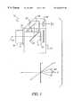
- FIG. 1is a schematic of a digital camera in accordance with the present invention, showing a back enclosure attached to a camera housing;
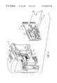
- FIG. 2is a rear view of the digital camera shown in FIG. 1 with the back enclosure removed and showing details of the alignment of a camera mounting plate to the digital camera in accordance with the present invention
- FIG. 3shows an image sensor mounting plate, an image sensor, and a circuit board in accordance with the present invention for use with the digital camera shown in FIGS. 1 and 2;
- FIG. 4shows an imager assembly including the components shown in FIG. 3 and showing details of the alignment of the image sensor mounting plate to the camera mounting plate of FIG. 2 .
- imaging devices employing electronic sensorsare well known, as are single lens reflex cameras and related components, the present description will be directed in particular to elements forming part of, or cooperating more directly with, apparatus in accordance with the present invention. Elements not specifically shown or described herein may be selected from those known in the art.
- a digital camera 10is shown mainly in schematic form to include a housing 12 and a back enclosure 14 .
- the housing 12is a conventional 35 mm single lens reflex (SLR) film camera body, such as a Nikon N90s SLR camera body.
- FIG. 2shows a rear view of the housing 12 as would be seen during the assembly operation.
- the housing 12includes a lens 16 , typically interchangeable, for directing image light along an optical axis 18 towards a pivotable mirror 20 , and a lens mount 17 .
- the pivotable mirror 20is in its down position, as shown in FIG.
- the image lightis directed upward toward an optical viewfinder 22 .
- a viewfinder imagewhich is formed on a focusing screen 24 , is viewed through an eyepiece 26 and a prism 28 .
- the pivotable mirror 20is raised to the position 20 ′, the image light is directed through an opening 30 (shown in FIG. 2) which cooperates with a focal plane shutter 31 , and forms an image on a focal plane 32 .
- a first camera pin 34is located above the focal plane shutter 31
- a second camera pin 36is located below the focal plane shutter 31
- a camera mounting plate 38is positioned parallel to the lens mount 17 , and is fixedly attached to the housing 12 at the focal plane 32 by, preferably, an adhesive. Other attaching arrangements can be used as well.
- the camera mounting plate 38is made of stainless steel.
- the camera mounting plate 38will now be described in more detail with reference to FIG. 2 . It will be appreciated by those skilled in the art that the camera mounting plate 38 replaces the conventional film rails used in a film camera to support a film at the focal plane. As shown in FIG. 2, the camera mounting plate 38 defines an opening 40 which is aligned with the focal plane shutter 31 of the camera housing 12 at the focal plane 32 . An alignment slot 42 and an alignment hole 44 formed on the camera mounting plate 38 correspond to the first and second camera pins 34 and 36 , respectively, for fixedly attaching a first surface 47 of the camera mounting plate 38 to the camera housing 12 . The alignment slot 40 and alignment hole 42 provide for alignment of an image sensor 46 (shown in FIG.
- FIG. 1shows a range of angles relative to the z-axis.
- theta x and theta y directionswhich are not shown for clarity of illustration.
- the camera mounting plate 38is then adhesively bonded to the camera housing 12 to provide alignment of the image sensor 46 in the z, theta x, and theta y directions.
- At least three spaced-apart alignment elements 50 , 52 , and 54 on a second surface 48 of the camera mounting plate 38are located a predetermined position relative to the lens mount 17 , and thus, to the lens 16 .
- the alignment elements 50 , 52 , and 54are protrusions which extend outwardly a minimum of approximately 0.38 mm from the second surface 48 of the camera mounting plate 38 .
- the alignment elements 50 , 52 , and 54are preferably located ⁇ 0.038 mm relative to each other to provide alignment of the image sensor 46 in the z, theta x, and theta y directions to control the depth of focus of the camera 10 .
- the alignment elements 50 , 52 , and 54could be positioned on the image sensor mounting plate 60 rather than on the camera mounting plate 38 .
- the alignment elements 50 , 52 , and 54are semi-circular in shape.
- the alignment elements 50 , 52 , and 54could take on various shapes to facilitate alignment of the image sensor 46 .
- an image sensor mounting plate 60supports the image sensor 46 in a central region thereof.
- the image sensor 46is optically aligned and adhesively bonded to the image sensor mounting plate 60 in a well-known manner.
- the image sensor 46 and image sensor mounting plate 60are then soldered to a circuit board 62 containing conventional circuitry for operating the image sensor 46 and for providing camera functions.
- This resulting imager assembly 64i.e., the image sensor mounting plate 60 , the image sensor 46 , and the circuit board 62 ), which is shown in FIG. 4, is then mounted to the camera mounting plate 38 so that the image sensor mounting plate 60 engages the protrusions 50 , 52 , and 54 on the camera mounting plate 38 .
- An alignment slot 61 and an alignment hole 63 formed in the image sensor mounting plate 60correspond to the alignment slot 42 and the alignment hole 44 , respectively, on the camera mounting plate 38 , and to the first and second camera pins 34 and 36 , respectively, on the camera housing 12 .
- This arrangementattaches the imager assembly 64 to the camera mounting plate 38 .
- the alignment slot 61 and alignment hole 63provide for alignment of the imager assembly 64 , and thus, the image sensor 46 to the camera mounting plate 38 in the x, y, and theta z directions.
- the imager assembly 64by mounting the imager assembly 64 to the camera mounting plate 38 with reference to the protrusions 50 , 52 , and 54 , the imager assembly 64 , and thus, the image sensor mounting plate 60 are aligned in the z, theta x, and theta y directions. In this manner, the image sensor 46 is accurately centered with respect to the optical axis 18 of the lens 16 at the focal plane 32 .
- the image sensor mounting plate 60is secured to the camera mounting plate 38 by at least three fasteners (shown in FIG. 4 ), which preferably are screws 56 . These screws 56 pass through at least three corresponding tapped fastening holes 66 (shown in FIG. 3) on the image sensor mounting plate 60 . The screws 56 are secured in at least three corresponding threaded fastening holes 68 (shown in FIG. 2) on the camera mounting plate 38 .
- the at least three threaded fastening holes 68 on the camera mounting plate 38are each positioned substantially close to one of the three protrusions 50 , 52 , and 54 .
- This structureminimizes any moment on the camera mounting plate 38 and thereby substantially eliminates any deflection of the camera mounting plate 38 when the imager assembly 64 is attached to the camera mounting plate 38 .
- three screws 56are used, and the threaded fastening holes 68 on the camera mounting plate 38 are each positioned within a maximum range of approximately 3.25 mm of a protrusion.
- the present inventionincluding the three protrusions 50 , 52 , and 54 on the camera mounting plate 38 provide for ease of serviceability and replacement of the imager assembly 64 while maintaining substantially no change in the z, theta x, and theta y directions.
- the focus and sharpness of the images captured by the digital camera 10can be maintained.
- the protrusions 50 , 52 , and 54are located a predetermined position relative to the lens 16 , the image sensor 46 is accurately centered with respect to the optical axis 18 of the lens 16 at the focal plane 32 . Accordingly, alignment of the image sensor 46 is independent of the actual image sensor that is used.
- the present inventionsubstantially eliminates any distortions in the images captured by the digital camera 10 that may be caused by warping or deflections in the camera mounting plate 38 or the image sensor mounting plate 60 .
Landscapes
- Engineering & Computer Science (AREA)
- Multimedia (AREA)
- Signal Processing (AREA)
- Studio Devices (AREA)
Abstract
Description
Claims (7)
Priority Applications (1)
| Application Number | Priority Date | Filing Date | Title |
|---|---|---|---|
| US09/332,645US6628339B1 (en) | 1999-06-14 | 1999-06-14 | Image sensor mount for a digital camera |
Applications Claiming Priority (1)
| Application Number | Priority Date | Filing Date | Title |
|---|---|---|---|
| US09/332,645US6628339B1 (en) | 1999-06-14 | 1999-06-14 | Image sensor mount for a digital camera |
Publications (1)
| Publication Number | Publication Date |
|---|---|
| US6628339B1true US6628339B1 (en) | 2003-09-30 |
Family
ID=28454521
Family Applications (1)
| Application Number | Title | Priority Date | Filing Date |
|---|---|---|---|
| US09/332,645Expired - LifetimeUS6628339B1 (en) | 1999-06-14 | 1999-06-14 | Image sensor mount for a digital camera |
Country Status (1)
| Country | Link |
|---|---|
| US (1) | US6628339B1 (en) |
Cited By (26)
| Publication number | Priority date | Publication date | Assignee | Title |
|---|---|---|---|---|
| US20010010562A1 (en)* | 2000-01-28 | 2001-08-02 | Asahi Kogaku Kogyo Kabushiki Kaisha | Structure for mounting a solid-state imaging device |
| US20050073602A1 (en)* | 2003-10-06 | 2005-04-07 | Masaaki Kamoda | Image pickup apparatus |
| US20050099521A1 (en)* | 2003-11-07 | 2005-05-12 | Scimeasure Analytical Systems, Inc. | Camera head enclosure |
| US20050195323A1 (en)* | 2004-03-05 | 2005-09-08 | Graham Luke A. | Optical module |
| WO2006037637A1 (en)* | 2004-10-06 | 2006-04-13 | Texmag Gmbh Vertriebsgesellschaft | Camera for detecting a moving product web |
| US20060120088A1 (en)* | 2004-12-03 | 2006-06-08 | Guenther Bryan W | Mounting mechanism for compensating optics in interferometer |
| EP1526717A3 (en)* | 2003-10-21 | 2006-07-12 | Robert Bosch Gmbh | Method and device for adjusting an optical module, and optical module |
| US20070035647A1 (en)* | 2005-08-10 | 2007-02-15 | Fuji Photo Film Co., Ltd. | Imaging device unit and camera system |
| US20070040926A1 (en)* | 2005-08-16 | 2007-02-22 | Fuji Photo Film Co., Ltd. | Replaceable imaging device unit, camera body and camera system |
| US20070096234A1 (en)* | 2005-11-02 | 2007-05-03 | Pentax Corporation | Image pickup device mounting structure |
| EP1841208A1 (en) | 2006-03-28 | 2007-10-03 | Fujinon Corporation | Camera unit and imaging apparatus |
| CN100428049C (en)* | 2004-07-21 | 2008-10-22 | 亚洲光学股份有限公司 | Optical center monitoring device and method |
| US20100319986A1 (en)* | 2009-06-17 | 2010-12-23 | Bleau Charles A | Modular vented circuit board enclosure |
| USD630598S1 (en) | 2009-06-18 | 2011-01-11 | Scimeasure Analytical Systems, Inc. | Modular enclosure |
| WO2013074578A1 (en)* | 2011-11-18 | 2013-05-23 | Uwm Research Foundation, Inc. | Ceramic camera for mri |
| US8659689B2 (en) | 2011-05-17 | 2014-02-25 | Rpx Corporation | Fast measurement of alignment data of a camera system |
| US20160021286A1 (en)* | 2013-03-27 | 2016-01-21 | Panasonic Intellectual Property Management Co., Ltd. | Imaging apparatus |
| US9584715B2 (en)* | 2015-02-16 | 2017-02-28 | Cognex Corporation | Vision system with swappable camera having an alignment indicator, and methods of making and using the same |
| WO2017200847A1 (en)* | 2016-05-19 | 2017-11-23 | Scenera, Inc. | Intelligent interface for interchangeable sensors |
| US10237457B2 (en)* | 2013-03-15 | 2019-03-19 | Nikon Corporation | Light receiving apparatus having body and exterior portion secured to mount |
| US10509459B2 (en) | 2016-05-19 | 2019-12-17 | Scenera, Inc. | Scene-based sensor networks |
| US10693843B2 (en) | 2016-09-02 | 2020-06-23 | Scenera, Inc. | Security for scene-based sensor networks |
| US10990840B2 (en) | 2019-03-15 | 2021-04-27 | Scenera, Inc. | Configuring data pipelines with image understanding |
| US11108938B2 (en)* | 2019-01-30 | 2021-08-31 | Canon Kabushiki Kaisha | Image pickup apparatus |
| US11157745B2 (en) | 2018-02-20 | 2021-10-26 | Scenera, Inc. | Automated proximity discovery of networked cameras |
| US20220272263A1 (en)* | 2020-09-01 | 2022-08-25 | Lineage Logistics, LLC | Image sensing assembly |
Citations (9)
| Publication number | Priority date | Publication date | Assignee | Title |
|---|---|---|---|---|
| JPS61245773A (en) | 1985-04-24 | 1986-11-01 | Mitsubishi Electric Corp | Video camera |
| US4803557A (en)* | 1988-01-11 | 1989-02-07 | Eastman Kodak Company | Adjustable mount for image sensor |
| US5221964A (en)* | 1991-08-05 | 1993-06-22 | Dalsa Inc | Electronically expandable modular ccd camera |
| US5483284A (en) | 1991-03-04 | 1996-01-09 | Nikon Corporation | Electronic still photographic adaptor mountable single-lens reflex camera |
| US5596229A (en)* | 1989-08-11 | 1997-01-21 | Raytheon Company | Chip carrier structure |
| US5781807A (en)* | 1996-08-16 | 1998-07-14 | Lester A. Dine, Inc. | Close-up attachment for a digital camera |
| US5861654A (en)* | 1995-11-28 | 1999-01-19 | Eastman Kodak Company | Image sensor assembly |
| US5946404A (en)* | 1995-06-01 | 1999-08-31 | Silent Witness Enterprises Ltd. | Audio/video surveillance and recording system |
| US6351288B1 (en)* | 1997-06-27 | 2002-02-26 | Eastman Kodak Company | Sensor tilt control for a digital camera |
- 1999
- 1999-06-14USUS09/332,645patent/US6628339B1/ennot_activeExpired - Lifetime
Patent Citations (9)
| Publication number | Priority date | Publication date | Assignee | Title |
|---|---|---|---|---|
| JPS61245773A (en) | 1985-04-24 | 1986-11-01 | Mitsubishi Electric Corp | Video camera |
| US4803557A (en)* | 1988-01-11 | 1989-02-07 | Eastman Kodak Company | Adjustable mount for image sensor |
| US5596229A (en)* | 1989-08-11 | 1997-01-21 | Raytheon Company | Chip carrier structure |
| US5483284A (en) | 1991-03-04 | 1996-01-09 | Nikon Corporation | Electronic still photographic adaptor mountable single-lens reflex camera |
| US5221964A (en)* | 1991-08-05 | 1993-06-22 | Dalsa Inc | Electronically expandable modular ccd camera |
| US5946404A (en)* | 1995-06-01 | 1999-08-31 | Silent Witness Enterprises Ltd. | Audio/video surveillance and recording system |
| US5861654A (en)* | 1995-11-28 | 1999-01-19 | Eastman Kodak Company | Image sensor assembly |
| US5781807A (en)* | 1996-08-16 | 1998-07-14 | Lester A. Dine, Inc. | Close-up attachment for a digital camera |
| US6351288B1 (en)* | 1997-06-27 | 2002-02-26 | Eastman Kodak Company | Sensor tilt control for a digital camera |
Cited By (49)
| Publication number | Priority date | Publication date | Assignee | Title |
|---|---|---|---|---|
| US6956615B2 (en)* | 2000-01-28 | 2005-10-18 | Pentax Corporation | Structure for mounting a solid-state imaging device |
| US20010010562A1 (en)* | 2000-01-28 | 2001-08-02 | Asahi Kogaku Kogyo Kabushiki Kaisha | Structure for mounting a solid-state imaging device |
| US20050073602A1 (en)* | 2003-10-06 | 2005-04-07 | Masaaki Kamoda | Image pickup apparatus |
| US7532247B2 (en)* | 2003-10-06 | 2009-05-12 | Tamron Co., Ltd. | Image pickup apparatus |
| EP1526717A3 (en)* | 2003-10-21 | 2006-07-12 | Robert Bosch Gmbh | Method and device for adjusting an optical module, and optical module |
| US7518654B2 (en)* | 2003-11-07 | 2009-04-14 | Scimeasure Analytical Systems, Inc. | Apparatuses for a camera head enclosure device for facilitating improved imaging |
| US20050099521A1 (en)* | 2003-11-07 | 2005-05-12 | Scimeasure Analytical Systems, Inc. | Camera head enclosure |
| US7839451B2 (en) | 2003-11-07 | 2010-11-23 | Scimeasure Analytical Systems, Inc. | Apparatuses and methods for a camera head enclosure device for facilitating improved imaging |
| US20090073308A1 (en)* | 2003-11-07 | 2009-03-19 | Scimeasure Analytical Systems, Inc. | Apparatuses and Methods for a Camera Head Enclosure Device for Facilitating Improved Imaging |
| US20050195323A1 (en)* | 2004-03-05 | 2005-09-08 | Graham Luke A. | Optical module |
| CN100428049C (en)* | 2004-07-21 | 2008-10-22 | 亚洲光学股份有限公司 | Optical center monitoring device and method |
| WO2006037637A1 (en)* | 2004-10-06 | 2006-04-13 | Texmag Gmbh Vertriebsgesellschaft | Camera for detecting a moving product web |
| US7212356B2 (en)* | 2004-12-03 | 2007-05-01 | Veeco Instruments Inc. | Mounting mechanism for compensating optics in interferometer |
| US20060120088A1 (en)* | 2004-12-03 | 2006-06-08 | Guenther Bryan W | Mounting mechanism for compensating optics in interferometer |
| US20070035647A1 (en)* | 2005-08-10 | 2007-02-15 | Fuji Photo Film Co., Ltd. | Imaging device unit and camera system |
| US20070040926A1 (en)* | 2005-08-16 | 2007-02-22 | Fuji Photo Film Co., Ltd. | Replaceable imaging device unit, camera body and camera system |
| US7645981B2 (en)* | 2005-11-02 | 2010-01-12 | Hoya Corporation | Image pickup device mounting structure for saving space in an optical device |
| JP2007128995A (en)* | 2005-11-02 | 2007-05-24 | Pentax Corp | Mounting structure for image sensor |
| US20070096234A1 (en)* | 2005-11-02 | 2007-05-03 | Pentax Corporation | Image pickup device mounting structure |
| CN101046598B (en)* | 2006-03-28 | 2011-03-16 | 富士能株式会社 | Camera unit and imaging apparatus |
| US20070229701A1 (en)* | 2006-03-28 | 2007-10-04 | Fujinon Corporation | Camera unit and imaging apparatus |
| EP1841208A1 (en) | 2006-03-28 | 2007-10-03 | Fujinon Corporation | Camera unit and imaging apparatus |
| US7961243B2 (en) | 2006-03-28 | 2011-06-14 | Fujinon Corporation | Camera unit and imaging apparatus |
| JP2007266887A (en)* | 2006-03-28 | 2007-10-11 | Fujinon Corp | Camera device and imaging device |
| US20100319986A1 (en)* | 2009-06-17 | 2010-12-23 | Bleau Charles A | Modular vented circuit board enclosure |
| USD630598S1 (en) | 2009-06-18 | 2011-01-11 | Scimeasure Analytical Systems, Inc. | Modular enclosure |
| US8659689B2 (en) | 2011-05-17 | 2014-02-25 | Rpx Corporation | Fast measurement of alignment data of a camera system |
| WO2013074578A1 (en)* | 2011-11-18 | 2013-05-23 | Uwm Research Foundation, Inc. | Ceramic camera for mri |
| US9599683B2 (en) | 2011-11-18 | 2017-03-21 | Uwm Research Foundation, Inc. | Ceramic camera for MRI |
| US11550206B2 (en) | 2013-03-15 | 2023-01-10 | Nikon Corporation | Light receiving apparatus with shock resistance |
| US10237457B2 (en)* | 2013-03-15 | 2019-03-19 | Nikon Corporation | Light receiving apparatus having body and exterior portion secured to mount |
| US20160021286A1 (en)* | 2013-03-27 | 2016-01-21 | Panasonic Intellectual Property Management Co., Ltd. | Imaging apparatus |
| US9609193B2 (en)* | 2013-03-27 | 2017-03-28 | Panasonic Intellectual Property Management Co., Ltd. | Compact interchangeable lens type camera |
| US9584715B2 (en)* | 2015-02-16 | 2017-02-28 | Cognex Corporation | Vision system with swappable camera having an alignment indicator, and methods of making and using the same |
| US10412291B2 (en) | 2016-05-19 | 2019-09-10 | Scenera, Inc. | Intelligent interface for interchangeable sensors |
| US11972036B2 (en) | 2016-05-19 | 2024-04-30 | Scenera, Inc. | Scene-based sensor networks |
| US10958820B2 (en) | 2016-05-19 | 2021-03-23 | Scenera, Inc. | Intelligent interface for interchangeable sensors |
| US10509459B2 (en) | 2016-05-19 | 2019-12-17 | Scenera, Inc. | Scene-based sensor networks |
| US10990162B2 (en) | 2016-05-19 | 2021-04-27 | Scenera, Inc. | Scene-based sensor networks |
| US11416063B2 (en) | 2016-05-19 | 2022-08-16 | Scenera, Inc. | Scene-based sensor networks |
| WO2017200847A1 (en)* | 2016-05-19 | 2017-11-23 | Scenera, Inc. | Intelligent interface for interchangeable sensors |
| US10693843B2 (en) | 2016-09-02 | 2020-06-23 | Scenera, Inc. | Security for scene-based sensor networks |
| US11245676B2 (en) | 2016-09-02 | 2022-02-08 | Scenera, Inc. | Security for scene-based sensor networks, with privacy management system |
| US12081527B2 (en) | 2016-09-02 | 2024-09-03 | Scenera, Inc. | Security for scene-based sensor networks, with access control |
| US11157745B2 (en) | 2018-02-20 | 2021-10-26 | Scenera, Inc. | Automated proximity discovery of networked cameras |
| US11108938B2 (en)* | 2019-01-30 | 2021-08-31 | Canon Kabushiki Kaisha | Image pickup apparatus |
| US10990840B2 (en) | 2019-03-15 | 2021-04-27 | Scenera, Inc. | Configuring data pipelines with image understanding |
| US11601594B2 (en)* | 2020-09-01 | 2023-03-07 | Lineage Logistics, LLC | Image sensing assembly |
| US20220272263A1 (en)* | 2020-09-01 | 2022-08-25 | Lineage Logistics, LLC | Image sensing assembly |
Similar Documents
| Publication | Publication Date | Title |
|---|---|---|
| US6628339B1 (en) | Image sensor mount for a digital camera | |
| US6910814B2 (en) | Digital camera system | |
| US7250972B2 (en) | Image-pickup apparatus with removable lens apparatus | |
| US4924247A (en) | Apparatus and method for correcting and adjusting parallax in electronic camera | |
| US7324748B2 (en) | Focal plane shutter and image sensing apparatus | |
| US7435020B2 (en) | Digital camera system, camera body of digital camera, and interchangeable lens | |
| US6603930B2 (en) | Camera | |
| GB2404447A (en) | Mirror box mounting in camera body | |
| JP4194449B2 (en) | Solid-state image sensor holding structure | |
| US5142312A (en) | Apparatus and method for correcting and adjusting parallax in electronic camera | |
| US5933670A (en) | Focal plane mounting for an image sensor | |
| JPH05203864A (en) | Image pickup device | |
| JPH08220409A (en) | Optical equipment | |
| JP7224865B2 (en) | How to adjust the imaging device | |
| US6328486B1 (en) | Camera | |
| JP3445049B2 (en) | Viewfinder for optical equipment | |
| JP6746466B2 (en) | Electronics | |
| JP2904375B2 (en) | Viewfinder mounting mechanism | |
| JPH0720537A (en) | Single-lens reflex camera viewfinder device | |
| JPS6374376A (en) | Video camera | |
| JP2000122166A (en) | Solid-state image pickup element attaching method and camera | |
| JPH09304678A (en) | Imaging device and video equipment system | |
| JP2006201456A (en) | camera | |
| JP2003207830A (en) | Camera body | |
| JPH07230117A (en) | Single-lens reflex camera viewfinder device |
Legal Events
| Date | Code | Title | Description |
|---|---|---|---|
| AS | Assignment | Owner name:EASTMAN KODAK COMPANY, NEW YORK Free format text:ASSIGNMENT OF ASSIGNORS INTEREST;ASSIGNORS:FERLAND, ALBERT;COSGROVE, STEPHEN R.;GIROUX, WILLIAM F.;REEL/FRAME:010039/0493 Effective date:19990614 | |
| STCF | Information on status: patent grant | Free format text:PATENTED CASE | |
| FEPP | Fee payment procedure | Free format text:PAYOR NUMBER ASSIGNED (ORIGINAL EVENT CODE: ASPN); ENTITY STATUS OF PATENT OWNER: LARGE ENTITY | |
| FPAY | Fee payment | Year of fee payment:4 | |
| FPAY | Fee payment | Year of fee payment:8 | |
| AS | Assignment | Owner name:CITICORP NORTH AMERICA, INC., AS AGENT, NEW YORK Free format text:SECURITY INTEREST;ASSIGNORS:EASTMAN KODAK COMPANY;PAKON, INC.;REEL/FRAME:028201/0420 Effective date:20120215 | |
| FEPP | Fee payment procedure | Free format text:PAYER NUMBER DE-ASSIGNED (ORIGINAL EVENT CODE: RMPN); ENTITY STATUS OF PATENT OWNER: LARGE ENTITY Free format text:PAYOR NUMBER ASSIGNED (ORIGINAL EVENT CODE: ASPN); ENTITY STATUS OF PATENT OWNER: LARGE ENTITY | |
| AS | Assignment | Owner name:KODAK PORTUGUESA LIMITED, NEW YORK Free format text:PATENT RELEASE;ASSIGNORS:CITICORP NORTH AMERICA, INC.;WILMINGTON TRUST, NATIONAL ASSOCIATION;REEL/FRAME:029913/0001 Effective date:20130201 Owner name:CREO MANUFACTURING AMERICA LLC, WYOMING Free format text:PATENT RELEASE;ASSIGNORS:CITICORP NORTH AMERICA, INC.;WILMINGTON TRUST, NATIONAL ASSOCIATION;REEL/FRAME:029913/0001 Effective date:20130201 Owner name:KODAK AVIATION LEASING LLC, NEW YORK Free format text:PATENT RELEASE;ASSIGNORS:CITICORP NORTH AMERICA, INC.;WILMINGTON TRUST, NATIONAL ASSOCIATION;REEL/FRAME:029913/0001 Effective date:20130201 Owner name:EASTMAN KODAK INTERNATIONAL CAPITAL COMPANY, INC., Free format text:PATENT RELEASE;ASSIGNORS:CITICORP NORTH AMERICA, INC.;WILMINGTON TRUST, NATIONAL ASSOCIATION;REEL/FRAME:029913/0001 Effective date:20130201 Owner name:EASTMAN KODAK COMPANY, NEW YORK Free format text:PATENT RELEASE;ASSIGNORS:CITICORP NORTH AMERICA, INC.;WILMINGTON TRUST, NATIONAL ASSOCIATION;REEL/FRAME:029913/0001 Effective date:20130201 Owner name:KODAK AMERICAS, LTD., NEW YORK Free format text:PATENT RELEASE;ASSIGNORS:CITICORP NORTH AMERICA, INC.;WILMINGTON TRUST, NATIONAL ASSOCIATION;REEL/FRAME:029913/0001 Effective date:20130201 Owner name:LASER-PACIFIC MEDIA CORPORATION, NEW YORK Free format text:PATENT RELEASE;ASSIGNORS:CITICORP NORTH AMERICA, INC.;WILMINGTON TRUST, NATIONAL ASSOCIATION;REEL/FRAME:029913/0001 Effective date:20130201 Owner name:KODAK REALTY, INC., NEW YORK Free format text:PATENT RELEASE;ASSIGNORS:CITICORP NORTH AMERICA, INC.;WILMINGTON TRUST, NATIONAL ASSOCIATION;REEL/FRAME:029913/0001 Effective date:20130201 Owner name:KODAK (NEAR EAST), INC., NEW YORK Free format text:PATENT RELEASE;ASSIGNORS:CITICORP NORTH AMERICA, INC.;WILMINGTON TRUST, NATIONAL ASSOCIATION;REEL/FRAME:029913/0001 Effective date:20130201 Owner name:KODAK IMAGING NETWORK, INC., CALIFORNIA Free format text:PATENT RELEASE;ASSIGNORS:CITICORP NORTH AMERICA, INC.;WILMINGTON TRUST, NATIONAL ASSOCIATION;REEL/FRAME:029913/0001 Effective date:20130201 Owner name:QUALEX INC., NORTH CAROLINA Free format text:PATENT RELEASE;ASSIGNORS:CITICORP NORTH AMERICA, INC.;WILMINGTON TRUST, NATIONAL ASSOCIATION;REEL/FRAME:029913/0001 Effective date:20130201 Owner name:FAR EAST DEVELOPMENT LTD., NEW YORK Free format text:PATENT RELEASE;ASSIGNORS:CITICORP NORTH AMERICA, INC.;WILMINGTON TRUST, NATIONAL ASSOCIATION;REEL/FRAME:029913/0001 Effective date:20130201 Owner name:PAKON, INC., INDIANA Free format text:PATENT RELEASE;ASSIGNORS:CITICORP NORTH AMERICA, INC.;WILMINGTON TRUST, NATIONAL ASSOCIATION;REEL/FRAME:029913/0001 Effective date:20130201 Owner name:NPEC INC., NEW YORK Free format text:PATENT RELEASE;ASSIGNORS:CITICORP NORTH AMERICA, INC.;WILMINGTON TRUST, NATIONAL ASSOCIATION;REEL/FRAME:029913/0001 Effective date:20130201 Owner name:KODAK PHILIPPINES, LTD., NEW YORK Free format text:PATENT RELEASE;ASSIGNORS:CITICORP NORTH AMERICA, INC.;WILMINGTON TRUST, NATIONAL ASSOCIATION;REEL/FRAME:029913/0001 Effective date:20130201 Owner name:FPC INC., CALIFORNIA Free format text:PATENT RELEASE;ASSIGNORS:CITICORP NORTH AMERICA, INC.;WILMINGTON TRUST, NATIONAL ASSOCIATION;REEL/FRAME:029913/0001 Effective date:20130201 | |
| AS | Assignment | Owner name:INTELLECTUAL VENTURES FUND 83 LLC, NEVADA Free format text:ASSIGNMENT OF ASSIGNORS INTEREST;ASSIGNOR:EASTMAN KODAK COMPANY;REEL/FRAME:030185/0725 Effective date:20130201 | |
| FPAY | Fee payment | Year of fee payment:12 | |
| AS | Assignment | Owner name:MONUMENT PEAK VENTURES, LLC, TEXAS Free format text:ASSIGNMENT OF ASSIGNORS INTEREST;ASSIGNOR:INTELLECTUAL VENTURES FUND 83 LLC;REEL/FRAME:041941/0079 Effective date:20170215 | |
| AS | Assignment | Owner name:MONUMENT PEAK VENTURES, LLC, TEXAS Free format text:RELEASE BY SECURED PARTY;ASSIGNOR:INTELLECTUAL VENTURES FUND 83 LLC;REEL/FRAME:064599/0304 Effective date:20230728 |