US6628237B1 - Remote communication using slot antenna - Google Patents
Remote communication using slot antennaDownload PDFInfo
- Publication number
- US6628237B1 US6628237B1US09/536,334US53633400AUS6628237B1US 6628237 B1US6628237 B1US 6628237B1US 53633400 AUS53633400 AUS 53633400AUS 6628237 B1US6628237 B1US 6628237B1
- Authority
- US
- United States
- Prior art keywords
- slot
- wireless communication
- communication device
- edge
- container
- Prior art date
- Legal status (The legal status is an assumption and is not a legal conclusion. Google has not performed a legal analysis and makes no representation as to the accuracy of the status listed.)
- Expired - Lifetime
Links
Images


Classifications
- H—ELECTRICITY
- H01—ELECTRIC ELEMENTS
- H01Q—ANTENNAS, i.e. RADIO AERIALS
- H01Q1/00—Details of, or arrangements associated with, antennas
- H01Q1/12—Supports; Mounting means
- H01Q1/22—Supports; Mounting means by structural association with other equipment or articles
- H01Q1/2208—Supports; Mounting means by structural association with other equipment or articles associated with components used in interrogation type services, i.e. in systems for information exchange between an interrogator/reader and a tag/transponder, e.g. in Radio Frequency Identification [RFID] systems
- H01Q1/2225—Supports; Mounting means by structural association with other equipment or articles associated with components used in interrogation type services, i.e. in systems for information exchange between an interrogator/reader and a tag/transponder, e.g. in Radio Frequency Identification [RFID] systems used in active tags, i.e. provided with its own power source or in passive tags, i.e. deriving power from RF signal
- B—PERFORMING OPERATIONS; TRANSPORTING
- B65—CONVEYING; PACKING; STORING; HANDLING THIN OR FILAMENTARY MATERIAL
- B65D—CONTAINERS FOR STORAGE OR TRANSPORT OF ARTICLES OR MATERIALS, e.g. BAGS, BARRELS, BOTTLES, BOXES, CANS, CARTONS, CRATES, DRUMS, JARS, TANKS, HOPPERS, FORWARDING CONTAINERS; ACCESSORIES, CLOSURES, OR FITTINGS THEREFOR; PACKAGING ELEMENTS; PACKAGES
- B65D25/00—Details of other kinds or types of rigid or semi-rigid containers
- B65D25/20—External fittings
- B65D25/205—Means for the attachment of labels, cards, coupons or the like
- G—PHYSICS
- G06—COMPUTING OR CALCULATING; COUNTING
- G06K—GRAPHICAL DATA READING; PRESENTATION OF DATA; RECORD CARRIERS; HANDLING RECORD CARRIERS
- G06K19/00—Record carriers for use with machines and with at least a part designed to carry digital markings
- G06K19/04—Record carriers for use with machines and with at least a part designed to carry digital markings characterised by the shape
- G06K19/041—Constructional details
- G—PHYSICS
- G06—COMPUTING OR CALCULATING; COUNTING
- G06K—GRAPHICAL DATA READING; PRESENTATION OF DATA; RECORD CARRIERS; HANDLING RECORD CARRIERS
- G06K19/00—Record carriers for use with machines and with at least a part designed to carry digital markings
- G06K19/06—Record carriers for use with machines and with at least a part designed to carry digital markings characterised by the kind of the digital marking, e.g. shape, nature, code
- G06K19/067—Record carriers with conductive marks, printed circuits or semiconductor circuit elements, e.g. credit or identity cards also with resonating or responding marks without active components
- G06K19/07—Record carriers with conductive marks, printed circuits or semiconductor circuit elements, e.g. credit or identity cards also with resonating or responding marks without active components with integrated circuit chips
- G06K19/077—Constructional details, e.g. mounting of circuits in the carrier
- G06K19/07749—Constructional details, e.g. mounting of circuits in the carrier the record carrier being capable of non-contact communication, e.g. constructional details of the antenna of a non-contact smart card
- G06K19/07773—Antenna details
- G06K19/07786—Antenna details the antenna being of the HF type, such as a dipole
- H—ELECTRICITY
- H01—ELECTRIC ELEMENTS
- H01Q—ANTENNAS, i.e. RADIO AERIALS
- H01Q1/00—Details of, or arrangements associated with, antennas
- H01Q1/12—Supports; Mounting means
- H01Q1/22—Supports; Mounting means by structural association with other equipment or articles
- H01Q1/2208—Supports; Mounting means by structural association with other equipment or articles associated with components used in interrogation type services, i.e. in systems for information exchange between an interrogator/reader and a tag/transponder, e.g. in Radio Frequency Identification [RFID] systems
- H—ELECTRICITY
- H01—ELECTRIC ELEMENTS
- H01Q—ANTENNAS, i.e. RADIO AERIALS
- H01Q1/00—Details of, or arrangements associated with, antennas
- H01Q1/44—Details of, or arrangements associated with, antennas using equipment having another main function to serve additionally as an antenna, e.g. means for giving an antenna an aesthetic aspect
- H—ELECTRICITY
- H01—ELECTRIC ELEMENTS
- H01Q—ANTENNAS, i.e. RADIO AERIALS
- H01Q13/00—Waveguide horns or mouths; Slot antennas; Leaky-waveguide antennas; Equivalent structures causing radiation along the transmission path of a guided wave
- H01Q13/10—Resonant slot antennas
- H—ELECTRICITY
- H01—ELECTRIC ELEMENTS
- H01Q—ANTENNAS, i.e. RADIO AERIALS
- H01Q13/00—Waveguide horns or mouths; Slot antennas; Leaky-waveguide antennas; Equivalent structures causing radiation along the transmission path of a guided wave
- H01Q13/10—Resonant slot antennas
- H01Q13/12—Longitudinally slotted cylinder antennas; Equivalent structures
- H—ELECTRICITY
- H01—ELECTRIC ELEMENTS
- H01Q—ANTENNAS, i.e. RADIO AERIALS
- H01Q13/00—Waveguide horns or mouths; Slot antennas; Leaky-waveguide antennas; Equivalent structures causing radiation along the transmission path of a guided wave
- H01Q13/10—Resonant slot antennas
- H01Q13/18—Resonant slot antennas the slot being backed by, or formed in boundary wall of, a resonant cavity ; Open cavity antennas
- B—PERFORMING OPERATIONS; TRANSPORTING
- B65—CONVEYING; PACKING; STORING; HANDLING THIN OR FILAMENTARY MATERIAL
- B65D—CONTAINERS FOR STORAGE OR TRANSPORT OF ARTICLES OR MATERIALS, e.g. BAGS, BARRELS, BOTTLES, BOXES, CANS, CARTONS, CRATES, DRUMS, JARS, TANKS, HOPPERS, FORWARDING CONTAINERS; ACCESSORIES, CLOSURES, OR FITTINGS THEREFOR; PACKAGING ELEMENTS; PACKAGES
- B65D2203/00—Decoration means, markings, information elements, contents indicators
- B65D2203/10—Transponders
Definitions
- the present inventionrelates generally to a device and method for identifying a container and, more particularly, to a device and method using the slot of the container as an antenna for remote communications.
- a wireless communication devicesuch as a radio frequency identification (RFID) transponder or other identification device
- RFIDradio frequency identification
- a liquid containersuch as a barrel or keg may include an identification device indicative of the liquid contained inside.
- the information communicated by the containers in the system to the interrogation readersmay be used for a number of reasons. For example, a statistical analysis may be made of the materials to maintain an accurate inventory, production flow rates, and other production standards. Additionally, the identification devices may include specific information about the materials housed within the containers including date of manufacture, place of manufacture, type of product within the container, temperature of the container and ambient air, temperature of the contents of the container, and pressure of the container, etc.
- the wireless communication devicemust have some type of antenna arrangement to communicate information about the containers to the interrogation readers. It is generally known for wireless communication devices to include an antenna. It is often a problem for many wireless communication devices to provide antenna especially if the wireless communication device is small or is required to be placed in a contained area.
- the length of the antennamust be tailored to the specific frequency that the wireless communication device is designed to operate. For low frequencies in the megahertz range or lower, an antenna may have to be several inches long to several feet long. Even for higher frequencies, the antenna may have to be several inches long to allow successful communication at the desired operating frequency.
- the antennamust either be packaged inside the wireless communication packaging or located external to the wireless communication device. External positioning of the antenna to the wireless communication device provides several other challenges when placing the wireless communication device in confined areas such as a container.
- the antennamay have additional problems radiating energy effectively if the antenna is contained internal to a device such as a container.
- a beer keghas a substantially cylindrical shape with a smooth, uniform outer wall. There are no extensions or areas for effectively attaching the wireless communication device. Even if the wireless communication device can be attached to the keg, additional problems in packaging and unaltered communication exists in including an antenna for the wireless communication device as described above.
- a beer kegis made out of a metal material that has an outer wall with a curled end to form a rim.
- the keg rimis used for handling and movement of the keg.
- the curled portion of the rimbends inward towards the outer wall leaving a small gap between the edge of the rim and outer wall.
- This small gapforms a slot that extends circularly around the keg and can be used to provide a slot antenna for the wireless communication device.
- the wireless communication devicecan be designed to provide electronic connectivity to the slot when installed so that the slot can be used to provide the effect of an antenna. Since the slot of the container may be several feet long, using the slot for the antenna may be advantageous for communication at lower frequencies where providing an antenna of sufficient length for communication at the desired frequency is problematic.
- the present inventionincludes a wireless communication device using a slot antenna arrangement formed by the slot of a container.
- a wireless communication deviceis provided with the container to provide information about the identification or other aspect of the container as it moves through manufacturing, tracking or shipping facilities.
- An antennais provided for the wireless communication device so that it can communicate remotely with a transmitter/receiver sometimes called an interrogation reader.
- the present inventioncapitalizes on the phenomenon that exists whereby a slot cut out of a conductive material such as metal can be coupled to a wireless communication device's communications electronics to provide the effect of a pole antenna.
- Some containershave by the nature of their construction a slot that can be used to provide a slot antenna.
- a slotcan also be cut out of the container as well.
- Using a slot antenna instead of a pole antennaprovides several advantages.
- the length of the slot for the wireless communication device to operate at the desired frequencymay be more suitable than could be provided by using a pole antenna.
- the slotdoes not require that a pole device be placed inside or proximate to the container. This is especially true for lower frequency communications that require longer length antennas.
- Using the slotmay also be less expensive than using a pole antenna.
- a pole antennamay extend from the container that may expose it to damage.
- the wireless communication deviceuses feed lines directly connected to the each edge of the slot.
- the wireless communication deviceincludes feed lines that reactively couple with each edge of the slot.
- a conductive deviceis placed between the slot to couple the wireless communication device to the slot and provide the slot antenna.
- the wireless communication deviceis mounted on a non-conductive substrate in the slot.
- a feed line from the wireless communication devicerests on the substrate such that it reactively couples with the slot to provide the slot antenna.
- a techniqueis provided to ensure that the operating frequency of the slot matches the operating frequency of the wireless communication device to maximize the slot antenna radiation efficiency.
- a circuitis provided in between the slot and the wireless communication device to match the impedance of the slot to the impedance of the wireless communication device.
- shorting postsare provided on the ends of the slot to create a slot with the desired length.
- the shorting postsare constructed out of a conductive material and are placed between the slot's edges to short both sides of the slot together.
- the inventionalso includes a method of monitoring the container. While the container is within a facility, such as during manufacturing, filling, or storing, the container is moved through at least one interrogation point containing an interrogation reader. Communication between the wireless communication device and the interrogation reader is established for monitoring the location and/or content information about the container.
- a central control systemmay be in communication with the interrogation point for monitoring the movement of the container. The central control system may monitor the position of the container, or it may also monitor specific information that is stored within memory in the device.
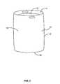
- FIG. 1is a perspective view of a container constructed in accordance with the present invention
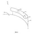
- FIG. 2is a cross sectional side view of the slot in the container
- FIG. 3is a schematic diagram illustrating communication between the transponder and an interrogation reader
- FIG. 4Ais a schematic view of the slot antenna using direct feed lines
- FIG. 4Bis a schematic view of the slot antenna using reactive feed lines
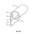
- FIG. 4Cis a schematic view of the slot antenna using a transponder mounting device as feed lines
- FIG. 4Dis a schematic view of the slot antenna using feed lines on a no-conductive substrate to couple to the slot;
- FIG. 5is a schematic diagram illustrating the radiation pattern of the slot antenna arrangement
- FIG. 6is a schematic diagram of an impedance matching circuit between the slot antenna and the transponder
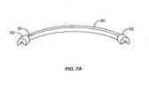
- FIG. 7Ais a schematic diagram of the slot antenna using shorting posts with one shorting post proximate to create a monopole antenna equivalent
- FIG. 7Bis a schematic diagram of a typical monopole antenna radiation pattern
- FIG. 8Ais a schematic diagram of the slot antenna using shorting posts with the transponder in between the shorting posts to create a dipole antenna equivalent
- FIG. 8Bis a schematic diagram of a typical dipole antenna radiation pattern
- FIG. 9is a schematic diagram illustrating the tracking and information system to track containers having a transponder.
- the present inventionis directed to a device and method of using a slot in a container as an antenna for a wireless communication device.
- the inventionincludes a wireless identification device 30 , called a “transponder,” that is mounted in a container 10 for identifying the container 10 .
- the container 10has outer walls 12 , including a bottom wall 18 , a top wall 19 , and outer walls 12 sealed together forming an enclosed chamber for housing a material 16 .
- a rim 14is formed by the outer wall 12 and may extend above the top wall 19 and the bottom wall 18 , for handling the container 10 .
- the outer wall 12extends upward and curls inward to form the rim 14 .
- the gap between the end of the curled outer wall and the outer wall 12is called the slot 20 that extends around the circumference of the container 10 .
- a transponder 30is provided within the rim 14 and preferably contains information about the container 10 that is communicated to at least one interrogation reader.
- FIG. 3illustrates one particular type of wireless communication device 30 called a radio frequency transponder 30 .
- the present inventionis described as using a transponder 30 as the wireless communication device as these terms are interchangeable. It should be readily understood to one of ordinary skill in the art that there are many other different types of wireless communication devices that allow electronic communication and therefore the present invention is not limited to any one particular type.
- the transponder 30includes a control system 34 and wireless communication electronics 32 .
- the transponder 30may also contain local memory 36 for storage of information to be communicated to an interrogation reader.
- the transponder 30may store information such as an identification number or indicia by using diodes, -dip switch or some other like circuitry, and is not limited to transponders 30 that contain memory 36 .
- An antenna 38is also provided for communication that may be either external to or incorporated internal to the transponder 30 . The particular type and location of the antenna 38 will depend on the operating frequency of the transponder 30 and the particular design desired.
- the control system 34is an integrated circuit or other type of microprocessor or micro-controller electronics that controls the substantive operations of the transponder 30 .
- the control system 34is connected to the wireless communication electronics 32 to communicate and receive transmissions.
- the control system 34is also connected to memory 36 for storing and retrieving information.
- Control system 34may further include a clock.
- FIG. 3also depicts how communication is achieved with the transponder 30 .
- An interrogation reader 40contains interrogation communication electronics 42 and an interrogation antenna 44 .
- the interrogation reader 40communicates to the transponder 30 by emitting an electronic signal or command 46 modulated in a frequency through the interrogation antenna 44 .
- the interrogation antenna 44may be any type of antenna that can radiate the modulated signal 46 through a field 48 so that a compatible device such as the transponder 30 can receive such signal 46 through its own antenna 38 .
- the field 48could be any of a variety of different types used in electronic communications including electromagnetic, magnetic, or electric.
- the signal 46is a message containing information and/or specific instructions for the transponder 30 .
- the wireless communication electronics 32When the transponder antenna 38 is in the presence of the field 48 emitted by the interrogation reader antenna 44 , the wireless communication electronics 32 are energized thereby energizing the transponder 30 . The transponder 30 remains energized so long as its antenna 38 is in the field 48 of the interrogation reader 40 .
- the wireless communication electronics 32demodulate the signal 46 and send the message containing information and/or specific instructions to the control system 34 for appropriate actions.
- the request in the messagemay be for the transponder 30 to send back its identification information about the container 10 or the materials 16 housed within the container 10 including date of manufacture, place of manufacture, and type of product within the container.
- the messagemay also be instructions to send back information regarding the temperature of the container, pressure levels, etc.
- the transponder 30communicates back the information requested to the interrogation reader 40 by altering the contents of the signal 46 .
- the transponder 30may have a transmitter that can send information to the interrogation reader 40 without having to use the signal 46 as the means for communication.
- the transponder 30may contain a battery to power the transmitter, or an energy storage unit that is charged by the energy when the device is in the field 48 of the signal 46 . It is understood to one of ordinary skill in the art there are many other manners in which to communicate with a wireless identification device such as a transponder 30 , and. that the present invention is not limited to the particular manner described above.
- FIGS. 4A-4Dshow various configurations of slot antenna arrangements to provide an antenna 38 by using the slot 20 in the container 10 as previously described.
- Voltage signalsare provided by the transponder 30 to opposites sides of the slot 20 .
- one side of the slot 20is formed by the outer wall 12 and the other side of the slot 20 is formed by the rim edge 52 .
- the slot 20radiates electro-magnetic waves similar to the manner in which a pole antenna arrangement would radiate to effectuate communications.
- FIG. 4Aillustrates a close-up of the outer wall 12 and the rim 14 illustrating how the transponder 30 uses the slot 20 as an antenna 38 using feed lines 54 .
- the transponder 30is located in the inner portion of the rim 14 .
- the slot 20is formed by the gap between the outer wall edge 50 and the rim edge 52 extends around the entire circumference of the container 10 .
- Feed lines 54are connected to the outer wall edge 50 and the rim edge 52 to provide an electrical connection between the transponder 30 , and particularly the wireless communication electronics 32 , and the slot 20 .
- FIG. 4Bcontains an embodiment whereby the feed line 54 from the transponder 30 does not directly connect to the outer wall edge 50 or the rim edge 52 . Instead, the feed line 54 is placed in close proximity to the outer wall edge 50 or the rim edge 52 to reactively couple to the slot 20 . The feed line 54 is still excited without direct contact between the feed line 54 and the slot 20 due to its close proximity to the slot 20 .
- FIG. 4Can embodiment is shown whereby a mounting device, called a conductive clip 60 in the preferred embodiment, provides a mounting technique for the transponder 30 and also provides a connection between the transponder's 30 wireless communication electronics 32 and the slot 20 to provide antenna 38 functionality.
- the conductive clip 60is substantially in the shape of an “R” in the preferred embodiment, however other types of clips with the same characteristics as described herein may also be used.
- the conductive clip 60has mounted to it the transponder 30 at the top of the conductive clip 60 .
- the conductive clip 60is inserted with the round portion. inside the slot 20 to provide a secure fit between the outer wall 12 and the rim edge 52 .
- the portion of the conductive clip 60 contacting the outer wall 12provides a ground plane 62 for the slot antenna 38 .
- the portion of the conductive clip 60 contacting the rim edge 52provides a connection or feed line 54 to the slot 20 to provide antenna 38 functionality for the transponder 30 .
- FIG. 4Dshows another alternative arrangement whereby the transponder 30 is mounted to a substrate material 70 .
- the substrate material 70is curled and placed inside the rim 14 whereby one side of the substrate material 70 contacts the outer wall 12 and the other side of the substrate material 70 contacts the rim edge 52 .
- the transponder 30has a feed line 54 that extends from the wireless communication electronics 32 and rests on the substrate material 70 , extending downward proximate to the rim edge 52 .
- the transponder 30 located proximate to the outer wall 12provides coupling to the outer wall creating a ground plane 62 with earth.
- the feed line 54extends to the rim edge 52 and is coupled with the rim edge 52 either as an open circuit or a short circuit to provide the optimum coupling of the transponder wireless communication electronics 32 to the slot 20 to create the slot antenna 38 depending on the length of the feed line 54 .
- FIG. 5illustrates the radiation pattern of a slot antenna 38 that has the same basic radiation pattern as a pole antenna arrangement such as a dipole antenna, but the E and H fields are interchanged.
- the radiation pattern of the slot antenna 38is a modified version of this radiation pattern due to both the curved nature of the slot 20 and the reflection from the surface of the container 10 . Therefore while it is noted that the radiation of the slot antenna 39 may have the characteristics of that illustrated in FIG. 5, such is provided for background purposes only and the present invention is not limited to a slot antenna 38 with such radiation pattern.
- the impedance of the slot 20When using a slot antenna 38 , it is desired for the impedance of the slot 20 to match the impedance of the transponder 30 at the desired frequency to maximize energy transfer from the transponder 30 to the slot antenna 38 for a maximum emitted radiation pattern. If the transponder 30 has a characteristic impedance that is not the conjugate of the slot 20 to maximize energy transfer, a matching network can be provided to do so.
- An antenna itselfcan be considered a matching network of sorts transforming its terminal impedance to 377 ohms, the impedance of free space.
- the impedance of the transponder 30may not be the same as the slot 20 . In this instance, the slot antenna 38 may not perform optimally since the maximum energy transfer would not occur between the transponder 30 and the slot antenna 38 .
- the slot antenna 38has a fairly low impedance. Therefore it is necessary to transform this impedance into the impedance of transponder 30 to maximum energy transfer and therefore maximize the strength of radiation pattern emitted by the slot antenna 38 .
- An impedance matching network illustrated in FIG. 6is provided to match the impedance of the slot 20 to the impedance of the transponder 30 ensure that the slot antenna 38 radiates an efficient radiation pattern for the operating frequency of the transponder 30 with minimal or no reflection.
- the matching network circuitconverts the impedance of the slot 20 to the impedance of the transponder 30 for an operating frequency of 868 MHz.
- the transponder 30has an impedance of 50 ohms.
- the matching network circuitis connected on the rim 14 and the outer wall 12 across the slot 20 in parallel with a capacitor 120 of approximately 3 pico Farads. Then connected in series to the node, connecting the circuit to the rim 14 and the capacitor 120 , is an inductor 122 of approximately 5 nano Henries. Another capacitor 124 of approximately 9 pico Farads is connected in series with the inductor 122 and in parallel with the node connecting the circuit to the outer wall 12 and the capacitor 120 . It should be noted that the characteristics of containers 10 and slot 20 impedances for desired frequencies may require different matching networks than described for the preferred embodiment and that the present invention is not limited hereto.
- the container 10has a continuous slot 20 that extends in a circular path. It may be desired to provide a technique or manner in which to define the length of the slot 20 so that the slot antenna 38 radiates in an improved manner at the operating frequency of the transponder 30 .
- One method of defining the slot 20 lengthis to provide shorting posts 82 as illustrated in FIGS. 7A and 8A to further improve performance of the slot antenna 38 depending on the frequency.
- the length of antenna or the slot 20 for a slot antenna 38is related to the radiation pattern of electronic signals radiated at the desired frequencies. For instance, the length of a dipole antenna is ⁇ divided by 2 where ⁇ is equal to the speed of light divided by the desired operating frequency.
- the length of the slot 20is defined by the boundaries, at which there is no longer a gap of space or the placement of conductive material.
- Some slot antennas 38are designed in containers 10 or other materials in which the slot 20 is placed at a predefined and desired length.
- the slot 20 lengthis defined by providing a conductive material in the slot 20 that shorts one side of the slot 20 to the other side. In the preferred embodiment, this is the outer wall 12 and the rim edge 52 . Shorting the slot 20 gives a finite length to the slot antenna 38 .
- Shorting posts 82are placed in the slot 20 at desired locations on each side of the location of transponder 30 coupled to the slot 20 to define the length of the slot 20 .
- An impedance matching networkmay or may not be necessary with shorting posts 82 depending if the impedance of the slot 20 and the impedance of the transponder 30 are matched sufficiently in order for the slot antenna 38 to emit a desired radiation pattern.
- FIG. 7illustrates an arrangement where one shorting post 82 is located near to or proximate to the transponder 30 and the other shorting post 82 is located a distance away from the transponder 30 .
- the transponder 30is mounted to a carrier material 80 that is placed inside the rim 14 for mounting the transponder 30 and shorting posts 82 .
- the carrier material 80is used as a convenient manner in which to mount the transponder 30 and the shorting posts 82 in the rim 14 of the container 10 .
- the carrier material 80is made out of a non-conductive material so that it does not conduct with the slot 20 , i.e. the outer wall 12 or the rim edge 52 .
- the transponder 30is coupled to the slot 20 to provide slot antenna 38 by techniques of coupling the transponder's 30 wireless communication electronics 32 as previously described above. Coupling the transponder 30 to the slot 20 at or proximate to one of the shorting posts 82 creates a slot antenna 38 similar to a radiation pattern of monopole antenna like that shown in FIG. 7B, but it should be noted that the exact radiation pattern of the slot antenna 38 may be different depending on the frequency of the transponder 30 and the shape and other characteristics of the container 10 .
- the transponder 30 and shorting posts 82are mounted on the carrier material 80 to mount inside the rim 14 of the container 10 similar to FIG. 7 A.
- the transponder 30is coupled to the slot 20 between the two shorting posts 82 .
- Coupling the transponder 30 to the slot 20 in the middle or center of the shorting posts 82creates a slot antenna 38 similar to a dipole like shown in FIG. 8B, but it should be noted that the exact radiation pattern of the slot antenna 38 may be different depending on the frequency of the transponder 30 and the shape and other characteristics of the container 10 .
- FIG. 9illustrates a tracking system in which containers 10 containing transponders 30 can be tracked through an environment such as a factory or distribution facility.
- the transponder 30 connected to container 10could pass a first interrogation point 90 that includes an interrogation reader 40 .
- a message containing information and/or a specific request for informationmay be transmitted by the interrogation reader 40 and received by the transponder 30 .
- This processcontinues as the container 10 moves to a second interrogation point 92 , a third interrogation point 94 , a fourth interrogation point 96 , and on to a last interrogation point 98 .
- a central control system 100maintains the information from the interrogation readers 40 and monitors the movement of the containers 10 through the facility.
- the information received by each of the interrogation readers 40may be forwarded to the central control system 100 either through direct wire or LAN connection.
- the central control system 100could also send information to the interrogation reader 40 to be transmitted to the transponder 30 for identification purposes.
- the central control system 100tracks the expected location of the containers 10 and may be alerted if it expects to receive information about a particular container and does not.
- each container 10During commissioning of each container 10 , it may be necessary to place the container 10 containing the transponder 30 in range of an interrogation reader 40 in order to erase previously stored information in memory, 36 or to store particular data or configuration information about the container 10 in memory 36 for later use.
Landscapes
- Engineering & Computer Science (AREA)
- Physics & Mathematics (AREA)
- General Physics & Mathematics (AREA)
- Theoretical Computer Science (AREA)
- Computer Hardware Design (AREA)
- Microelectronics & Electronic Packaging (AREA)
- Computer Networks & Wireless Communication (AREA)
- Mechanical Engineering (AREA)
- Support Of Aerials (AREA)
- Near-Field Transmission Systems (AREA)
- Details Of Aerials (AREA)
- Waveguide Aerials (AREA)
- Automatic Analysis And Handling Materials Therefor (AREA)
- Transceivers (AREA)
Abstract
Description
Claims (44)
Priority Applications (12)
| Application Number | Priority Date | Filing Date | Title |
|---|---|---|---|
| US09/536,334US6628237B1 (en) | 2000-03-25 | 2000-03-25 | Remote communication using slot antenna |
| AU2001242571AAU2001242571A1 (en) | 2000-03-25 | 2001-03-23 | A device for identifying a container |
| EP01915479AEP1269395B1 (en) | 2000-03-25 | 2001-03-23 | A device for identifying a container |
| PCT/GB2001/001295WO2001073675A2 (en) | 2000-03-25 | 2001-03-23 | A device for identifying a container |
| JP2001571318AJP4388725B2 (en) | 2000-03-25 | 2001-03-23 | Device for identifying containers |
| DE60132881TDE60132881T2 (en) | 2000-03-25 | 2001-03-23 | DEVICE FOR IDENTIFYING A CONTAINER |
| AT01915479TATE386992T1 (en) | 2000-03-25 | 2001-03-23 | DEVICE FOR IDENTIFYING A CONTAINER |
| US10/125,783US6985119B2 (en) | 2000-03-25 | 2002-04-18 | Multiple feed point slot antenna |
| US10/125,786US6642897B2 (en) | 2000-03-25 | 2002-04-18 | Tuning techniques for a slot antenna |
| US11/267,920USRE40972E1 (en) | 2000-03-25 | 2005-11-04 | Tuning techniques for a slot antenna |
| US11/318,339US7528785B2 (en) | 2000-03-25 | 2005-12-23 | Multiple feed point slot antenna |
| US11/469,360US7432869B2 (en) | 2000-03-25 | 2006-08-31 | Multiple feed point slot antenna |
Applications Claiming Priority (1)
| Application Number | Priority Date | Filing Date | Title |
|---|---|---|---|
| US09/536,334US6628237B1 (en) | 2000-03-25 | 2000-03-25 | Remote communication using slot antenna |
Related Child Applications (2)
| Application Number | Title | Priority Date | Filing Date |
|---|---|---|---|
| US10/125,783Continuation-In-PartUS6985119B2 (en) | 2000-03-25 | 2002-04-18 | Multiple feed point slot antenna |
| US10/125,786Continuation-In-PartUS6642897B2 (en) | 2000-03-25 | 2002-04-18 | Tuning techniques for a slot antenna |
Publications (1)
| Publication Number | Publication Date |
|---|---|
| US6628237B1true US6628237B1 (en) | 2003-09-30 |
Family
ID=24138085
Family Applications (6)
| Application Number | Title | Priority Date | Filing Date |
|---|---|---|---|
| US09/536,334Expired - LifetimeUS6628237B1 (en) | 2000-03-25 | 2000-03-25 | Remote communication using slot antenna |
| US10/125,786CeasedUS6642897B2 (en) | 2000-03-25 | 2002-04-18 | Tuning techniques for a slot antenna |
| US10/125,783Expired - LifetimeUS6985119B2 (en) | 2000-03-25 | 2002-04-18 | Multiple feed point slot antenna |
| US11/267,920Expired - LifetimeUSRE40972E1 (en) | 2000-03-25 | 2005-11-04 | Tuning techniques for a slot antenna |
| US11/318,339Expired - Fee RelatedUS7528785B2 (en) | 2000-03-25 | 2005-12-23 | Multiple feed point slot antenna |
| US11/469,360Expired - LifetimeUS7432869B2 (en) | 2000-03-25 | 2006-08-31 | Multiple feed point slot antenna |
Family Applications After (5)
| Application Number | Title | Priority Date | Filing Date |
|---|---|---|---|
| US10/125,786CeasedUS6642897B2 (en) | 2000-03-25 | 2002-04-18 | Tuning techniques for a slot antenna |
| US10/125,783Expired - LifetimeUS6985119B2 (en) | 2000-03-25 | 2002-04-18 | Multiple feed point slot antenna |
| US11/267,920Expired - LifetimeUSRE40972E1 (en) | 2000-03-25 | 2005-11-04 | Tuning techniques for a slot antenna |
| US11/318,339Expired - Fee RelatedUS7528785B2 (en) | 2000-03-25 | 2005-12-23 | Multiple feed point slot antenna |
| US11/469,360Expired - LifetimeUS7432869B2 (en) | 2000-03-25 | 2006-08-31 | Multiple feed point slot antenna |
Country Status (7)
| Country | Link |
|---|---|
| US (6) | US6628237B1 (en) |
| EP (1) | EP1269395B1 (en) |
| JP (1) | JP4388725B2 (en) |
| AT (1) | ATE386992T1 (en) |
| AU (1) | AU2001242571A1 (en) |
| DE (1) | DE60132881T2 (en) |
| WO (1) | WO2001073675A2 (en) |
Cited By (17)
| Publication number | Priority date | Publication date | Assignee | Title |
|---|---|---|---|---|
| US20040036657A1 (en)* | 2002-04-24 | 2004-02-26 | Forster Ian J. | Energy source communication employing slot antenna |
| US20040041706A1 (en)* | 2002-09-04 | 2004-03-04 | Stratmoen Scott Alan | Smart and secure container |
| US20060250314A1 (en)* | 2000-03-25 | 2006-11-09 | Mineral Lassen Llc | Multiple feed point slot antenna |
| US20070017986A1 (en)* | 2005-07-19 | 2007-01-25 | Carrender Curtis L | Radio frequency identification with a slot antenna |
| WO2008000425A1 (en)* | 2006-06-26 | 2008-01-03 | Giesecke & Devrient Gmbh | Method for producing a transponder |
| US20090027297A1 (en)* | 2005-06-01 | 2009-01-29 | Hardy Zissel | Arrangement with a transponder and a metal element |
| WO2009018922A1 (en)* | 2007-08-09 | 2009-02-12 | Alcan Technology & Management Ltd. | Product packaging having a cover foil |
| WO2009027854A1 (en)* | 2007-08-30 | 2009-03-05 | Abraham Gert Willem Du Plooy | A radio frequency (rf) tag |
| US20090079568A1 (en)* | 2007-09-26 | 2009-03-26 | Forster Ian J | Rfid interposer with impedance matching |
| US20090140860A1 (en)* | 2007-12-03 | 2009-06-04 | Forster Ian J | Dual use rfid/eas device |
| US20090146783A1 (en)* | 2007-12-05 | 2009-06-11 | Forster Ian J | Rfid system with distributed read structure |
| US20090146785A1 (en)* | 2007-12-11 | 2009-06-11 | Forster Ian J | Rfid device with multiple passive operation modes |
| US7768407B2 (en) | 2007-06-22 | 2010-08-03 | Avery Dennison Corporation | Foldable RFID device interposer and method |
| EP2244210A1 (en)* | 2009-04-22 | 2010-10-27 | Fujitsu Limited | RFID tag |
| US20180162636A1 (en)* | 2016-12-13 | 2018-06-14 | Sigma-Aldrich International Gmbh | Electronics assembly for wireless transmission of at least one status information |
| WO2020065554A1 (en)* | 2018-09-26 | 2020-04-02 | ACTA S.r.L. | Container for hazardous waste |
| US20220355971A1 (en)* | 2019-09-23 | 2022-11-10 | Carlsberg Breweries A/S | RFID-equipped pressure chamber for keg |
Families Citing this family (83)
| Publication number | Priority date | Publication date | Assignee | Title |
|---|---|---|---|---|
| US6806842B2 (en) | 2000-07-18 | 2004-10-19 | Marconi Intellectual Property (Us) Inc. | Wireless communication device and method for discs |
| US6483473B1 (en) | 2000-07-18 | 2002-11-19 | Marconi Communications Inc. | Wireless communication device and method |
| US7098850B2 (en) | 2000-07-18 | 2006-08-29 | King Patrick F | Grounded antenna for a wireless communication device and method |
| US7702418B2 (en)* | 2001-06-13 | 2010-04-20 | Advanced Technology Materials, Inc. | Secure reader system |
| US6879876B2 (en)* | 2001-06-13 | 2005-04-12 | Advanced Technology Materials, Inc. | Liquid handling system with electronic information storage |
| US6630910B2 (en) | 2001-10-29 | 2003-10-07 | Marconi Communications Inc. | Wave antenna wireless communication device and method |
| US7691244B2 (en)* | 2001-12-18 | 2010-04-06 | Massachusetts Institute Of Technology | Microfluidic pumps and mixers driven by induced-charge electro-osmosis |
| ATE474287T1 (en) | 2002-04-24 | 2010-07-15 | Mineral Lassen Llc | PRODUCTION METHOD FOR A WIRELESS COMMUNICATION DEVICE AND PRODUCTION APPARATUS |
| FR2839392B1 (en)* | 2002-05-06 | 2004-06-18 | Commissariat Energie Atomique | DEVICE FOR TRANSMITTING ELECTROMAGNETIC RADIATION THROUGH A WALL |
| US7920827B2 (en)* | 2002-06-26 | 2011-04-05 | Nokia Corporation | Apparatus and method for facilitating physical browsing on wireless devices using radio frequency identification |
| JP3803085B2 (en)* | 2002-08-08 | 2006-08-02 | 株式会社日立製作所 | Wireless IC tag |
| US7108880B2 (en)* | 2003-02-14 | 2006-09-19 | Waldron Llc | Confectionery composition and methods of using the same for decorating |
| US20060244599A1 (en)* | 2003-10-22 | 2006-11-02 | Mobile Aspects, Inc. | Identification apparatus |
| US7138955B2 (en)* | 2003-10-23 | 2006-11-21 | Michelin Recherche Et Technique S.A. | Robust antenna connection for an electronics component assembly in a tire |
| ATE392000T1 (en)* | 2004-05-26 | 2008-04-15 | Siemens Ag | CONTACT SYSTEM |
| US7549591B2 (en)* | 2004-06-28 | 2009-06-23 | International Barcode Corporation | Combined multi-frequency electromagnetic and optical communication system |
| US7284704B2 (en)* | 2004-06-28 | 2007-10-23 | International Barcode Corporation | Combined electromagnetic and optical communication system |
| US7274297B2 (en)* | 2004-07-01 | 2007-09-25 | Intermec Ip Corp. | RFID tag and method of manufacture |
| US20060208886A1 (en)* | 2005-03-01 | 2006-09-21 | Static Control Components, Inc. | Systems and methods for providing packages with RFID tags |
| US7268742B2 (en)* | 2005-03-22 | 2007-09-11 | Mobile Aspects, Inc. | Antenna arrangement |
| US7501947B2 (en)* | 2005-05-04 | 2009-03-10 | Tc License, Ltd. | RFID tag with small aperture antenna |
| WO2007000578A2 (en) | 2005-06-25 | 2007-01-04 | Omni-Id Limited | Electromagnetic radiation decoupler |
| GB2428424A (en)* | 2005-07-16 | 2007-01-31 | Linpac Materials Handling Ltd | Stackable crate having a RF identification device |
| US7777626B2 (en)* | 2005-10-13 | 2010-08-17 | BAE Systems Information and Electronic Systems, Integration, Inc. | RFID tag incorporating at least two integrated circuits |
| DE102006029248A1 (en) | 2005-10-26 | 2007-05-16 | Giesecke & Devrient Gmbh | transponder |
| US7573388B2 (en)* | 2005-12-08 | 2009-08-11 | The Kennedy Group, Inc. | RFID device with augmented grain |
| US7750813B2 (en)* | 2005-12-14 | 2010-07-06 | University Of Kansas | Microstrip antenna for RFID device |
| US8564439B2 (en) | 2010-05-27 | 2013-10-22 | The University Of Kansas | Microstrip antenna for RFID device |
| US7519328B2 (en) | 2006-01-19 | 2009-04-14 | Murata Manufacturing Co., Ltd. | Wireless IC device and component for wireless IC device |
| CN101351924A (en)* | 2006-01-19 | 2009-01-21 | 株式会社村田制作所 | Wireless IC device and component for wireless IC device |
| KR101050330B1 (en)* | 2006-01-19 | 2011-07-19 | 가부시키가이샤 무라타 세이사쿠쇼 | Radio ic device and radio ic device part |
| JP4786361B2 (en)* | 2006-02-09 | 2011-10-05 | 京セラミタ株式会社 | Image forming apparatus |
| CN101948025B (en)* | 2006-02-22 | 2012-05-30 | 东洋制罐株式会社 | Metal cover with RFID tag and metal article |
| WO2007141733A2 (en)* | 2006-06-09 | 2007-12-13 | Idtek Track-And-Trace Sa | Bottle of gas including a transponder |
| GB0611983D0 (en) | 2006-06-16 | 2006-07-26 | Qinetiq Ltd | Electromagnetic radiation decoupler |
| DE102006029249A1 (en)* | 2006-06-26 | 2007-12-27 | Giesecke & Devrient Gmbh | Method for mounting a transponder on an object |
| KR101422303B1 (en) | 2006-07-10 | 2014-08-13 | 어드밴스드 테크놀러지 머티리얼즈, 인코포레이티드 | Systems and methods for managing material storage vessels having information storage elements |
| NL1032542C2 (en)* | 2006-09-20 | 2008-03-21 | Knieriem B V J | Vehicle identification. |
| US7564356B1 (en) | 2006-10-06 | 2009-07-21 | Tc License, Ltd. | Interdigit AC coupling for RFID tags |
| GB0624915D0 (en)* | 2006-12-14 | 2007-01-24 | Qinetiq Ltd | Switchable radiation decoupling |
| GB0625342D0 (en)* | 2006-12-20 | 2007-01-24 | Qinetiq Ltd | Radiation decoupling |
| EP2150313B1 (en) | 2007-04-24 | 2013-06-19 | St. Jude Medical AB | Container for storing an implantable medical device, and a method for packaging such a device |
| JP4420070B2 (en)* | 2007-06-20 | 2010-02-24 | ブラザー工業株式会社 | Image forming apparatus |
| TW200904733A (en)* | 2007-07-26 | 2009-02-01 | Yfy Rfid Technologies Company Ltd | Radio frequency identification tag holder and paper roll assembly |
| US20090044385A1 (en)* | 2007-08-16 | 2009-02-19 | Honda Motor Co., Ltd. | Universal spring-clip mounting device for object identifying devices |
| US8121539B2 (en)* | 2007-08-27 | 2012-02-21 | Nokia Corporation | Antenna arrangement |
| US8794533B2 (en)* | 2008-08-20 | 2014-08-05 | Omni-Id Cayman Limited | One and two-part printable EM tags |
| KR101923742B1 (en) | 2010-05-12 | 2018-11-29 | 네스텍 소시에테아노님 | Support and capsule for preparing a beverage by centrifugation, system and method for preparing a beverage by centrifugation |
| US8842044B2 (en) | 2010-08-27 | 2014-09-23 | Netgear, Inc. | Apparatus and method for operation of an antenna system enabling control of radiation characteristics |
| DE102011018877A1 (en)* | 2011-04-28 | 2012-10-31 | Dresden Informatik Gmbh | Method for bulk detection of reusable drink barrels, involves arranging on-metal transponders centrally and transversely to longitudinal direction of slot in grip ring |
| TWI508365B (en)* | 2012-05-04 | 2015-11-11 | Yageo Corp | Antenna having connecting circuit |
| CH706852A1 (en)* | 2012-08-21 | 2014-02-28 | Ymatron Ag | Disposal container. |
| USD698683S1 (en)* | 2012-12-13 | 2014-02-04 | Assa Abloy Ab | UHF keg tag |
| DE102013202930A1 (en)* | 2013-02-22 | 2014-09-11 | Siemens Aktiengesellschaft | Wireless charging system for hearing instruments |
| AT514661A1 (en)* | 2013-07-25 | 2015-02-15 | Seibersdorf Labor Gmbh | container |
| WO2015056048A1 (en)* | 2013-10-14 | 2015-04-23 | Uab "Acorn Intelligence" | Method for producing and modifying open or closed containers providing properties of an antenna |
| TWI539678B (en)* | 2014-05-16 | 2016-06-21 | 宏碁股份有限公司 | Communication device |
| US9668060B2 (en)* | 2015-08-04 | 2017-05-30 | Curtis E. Graber | Transducer |
| US11172308B2 (en) | 2015-08-04 | 2021-11-09 | Curtis E. Graber | Electric motor |
| US10375479B2 (en) | 2015-08-04 | 2019-08-06 | Curtis E. Graber | Electric motor |
| US10063100B2 (en) | 2015-08-07 | 2018-08-28 | Nucurrent, Inc. | Electrical system incorporating a single structure multimode antenna for wireless power transmission using magnetic field coupling |
| US11205848B2 (en) | 2015-08-07 | 2021-12-21 | Nucurrent, Inc. | Method of providing a single structure multi mode antenna having a unitary body construction for wireless power transmission using magnetic field coupling |
| US10658847B2 (en) | 2015-08-07 | 2020-05-19 | Nucurrent, Inc. | Method of providing a single structure multi mode antenna for wireless power transmission using magnetic field coupling |
| US10985465B2 (en) | 2015-08-19 | 2021-04-20 | Nucurrent, Inc. | Multi-mode wireless antenna configurations |
| US10008762B2 (en)* | 2016-01-22 | 2018-06-26 | Fractus Antennas, S.L. | Wireless device including optimized antenna system on metal frame |
| US20180062434A1 (en) | 2016-08-26 | 2018-03-01 | Nucurrent, Inc. | Wireless Connector Receiver Module Circuit |
| US10432031B2 (en) | 2016-12-09 | 2019-10-01 | Nucurrent, Inc. | Antenna having a substrate configured to facilitate through-metal energy transfer via near field magnetic coupling |
| US11502547B2 (en) | 2017-02-13 | 2022-11-15 | Nucurrent, Inc. | Wireless electrical energy transmission system with transmitting antenna having magnetic field shielding panes |
| US11283295B2 (en) | 2017-05-26 | 2022-03-22 | Nucurrent, Inc. | Device orientation independent wireless transmission system |
| SE542229C2 (en) | 2018-07-02 | 2020-03-17 | Stora Enso Oyj | A metal container comprising a uhf rfid tag |
| US11271430B2 (en) | 2019-07-19 | 2022-03-08 | Nucurrent, Inc. | Wireless power transfer system with extended wireless charging range |
| US11227712B2 (en) | 2019-07-19 | 2022-01-18 | Nucurrent, Inc. | Preemptive thermal mitigation for wireless power systems |
| US20210081891A1 (en)* | 2019-09-17 | 2021-03-18 | Altair Engineering, Inc. | Systems and Methods for Tracking Beer Kegs and other Fluid Vessels |
| CN110561072B (en)* | 2019-09-18 | 2020-08-04 | 卢丽花 | Use method of station material distribution equipment |
| US11056922B1 (en) | 2020-01-03 | 2021-07-06 | Nucurrent, Inc. | Wireless power transfer system for simultaneous transfer to multiple devices |
| US11283303B2 (en) | 2020-07-24 | 2022-03-22 | Nucurrent, Inc. | Area-apportioned wireless power antenna for maximized charging volume |
| US11881716B2 (en) | 2020-12-22 | 2024-01-23 | Nucurrent, Inc. | Ruggedized communication for wireless power systems in multi-device environments |
| US11876386B2 (en) | 2020-12-22 | 2024-01-16 | Nucurrent, Inc. | Detection of foreign objects in large charging volume applications |
| DE102021100372A1 (en) | 2021-01-12 | 2022-07-14 | Georg Bauerfeind | Valve insert of a beverage keg as well as monitoring system and method for monitoring beverage kegs |
| US11695302B2 (en) | 2021-02-01 | 2023-07-04 | Nucurrent, Inc. | Segmented shielding for wide area wireless power transmitter |
| CN118661178A (en)* | 2022-02-09 | 2024-09-17 | 艾利丹尼森零售信息服务有限公司 | Metal package with integrated RFID inlay |
| US12003116B2 (en) | 2022-03-01 | 2024-06-04 | Nucurrent, Inc. | Wireless power transfer system for simultaneous transfer to multiple devices with cross talk and interference mitigation |
| US11831174B2 (en) | 2022-03-01 | 2023-11-28 | Nucurrent, Inc. | Cross talk and interference mitigation in dual wireless power transmitter |
Citations (18)
| Publication number | Priority date | Publication date | Assignee | Title |
|---|---|---|---|---|
| DE444623C (en) | 1927-05-23 | Erste Automatische Gussstahlku | Roller hub for the wheels of strollers | |
| US3961323A (en) | 1971-02-22 | 1976-06-01 | American Multi-Lert Corporation | Cargo monitor apparatus and method |
| US4051480A (en) | 1976-10-27 | 1977-09-27 | The United States Of America As Represented By The Secretary Of The Army | Conformal edge-slot radiators |
| US4086598A (en) | 1976-12-02 | 1978-04-25 | Bogner Richard D | Broadband omnidirectional slot antenna with an electrical strap connector |
| US5255819A (en) | 1990-02-09 | 1993-10-26 | Peckels Arganious E | Method and apparatus for manual dispensing from discrete vessels with electronic system control and dispensing data generation on each vessel, data transmission by radio or interrogator, and remote data recording |
| US5461393A (en) | 1993-08-20 | 1995-10-24 | Texas Instruments Incorporated | Dual frequency cavity backed slot antenna |
| US5495218A (en) | 1994-04-20 | 1996-02-27 | Thermo Instrument Controls Inc. | Microwave waveguide seal assembly |
| US5507411A (en) | 1990-02-09 | 1996-04-16 | Berg Company, A Division Of Dec International, Inc. | Electronic dispensing heads |
| US5621419A (en) | 1994-05-26 | 1997-04-15 | Schlumberger Industries Limited | Circular slot antenna |
| US5691731A (en) | 1993-06-15 | 1997-11-25 | Texas Instruments Incorporated | Closed slot antenna having outer and inner magnetic loops |
| US5774876A (en) | 1996-06-26 | 1998-06-30 | Par Government Systems Corporation | Managing assets with active electronic tags |
| US5864323A (en) | 1995-12-22 | 1999-01-26 | Texas Instruments Incorporated | Ring antennas for resonant circuits |
| US5914640A (en) | 1996-02-29 | 1999-06-22 | Texas Instruments Incorporated | Method and system for matching the input impedance of an RF amplifier an antenna to impedance |
| US5929813A (en) | 1998-01-09 | 1999-07-27 | Nokia Mobile Phones Limited | Antenna for mobile communications device |
| WO1999065002A1 (en) | 1998-06-09 | 1999-12-16 | Motorola Inc. | Radio frequency identification tag having an article integrated antenna |
| US6018299A (en) | 1998-06-09 | 2000-01-25 | Motorola, Inc. | Radio frequency identification tag having a printed antenna and method |
| US6023244A (en) | 1997-02-14 | 2000-02-08 | Telefonaktiebolaget Lm Ericsson | Microstrip antenna having a metal frame for control of an antenna lobe |
| US6385407B1 (en)* | 1998-12-28 | 2002-05-07 | Hitachi Maxell, Ltd. | Accommodating enclosure and management system |
Family Cites Families (20)
| Publication number | Priority date | Publication date | Assignee | Title |
|---|---|---|---|---|
| JPS5958819A (en)* | 1982-09-29 | 1984-04-04 | Hitachi Ltd | Formation of thin film |
| US4782345A (en) | 1986-07-29 | 1988-11-01 | Amtech Corporation | Transponder antenna |
| KR920002439B1 (en) | 1988-08-31 | 1992-03-24 | 삼성전자 주식회사 | Slot antenna device for portable radiophone |
| US5339074A (en)* | 1991-09-13 | 1994-08-16 | Fluoroware, Inc. | Very low frequency tracking system |
| US5448220A (en)* | 1993-04-08 | 1995-09-05 | Levy; Raymond H. | Apparatus for transmitting contents information |
| US5682143A (en) | 1994-09-09 | 1997-10-28 | International Business Machines Corporation | Radio frequency identification tag |
| DE4446203A1 (en)* | 1994-12-23 | 1996-06-27 | Hartmut Keuper | Process for digitally recording the circulation of beer kegs |
| US6008770A (en) | 1996-06-24 | 1999-12-28 | Ricoh Company, Ltd. | Planar antenna and antenna array |
| US6085076A (en) | 1997-04-07 | 2000-07-04 | Omnipoint Corporation | Antenna diversity for wireless communication system |
| US5906031A (en) | 1998-04-17 | 1999-05-25 | Hughes Electronics Corporation | Rotating and locking clip for portable electronic device |
| US6072437A (en) | 1998-06-29 | 2000-06-06 | Ems Technologies, Inc. | Antenna exhibiting azimuth and elevation beam shaping characteristics |
| US6538569B1 (en)* | 1998-10-30 | 2003-03-25 | The Goodyear Tire & Rubber Company | Container with sensor |
| US6784789B2 (en)* | 1999-07-08 | 2004-08-31 | Intermec Ip Corp. | Method and apparatus for verifying RFID tags |
| US6784802B1 (en)* | 1999-11-04 | 2004-08-31 | Nordx/Cdt, Inc. | Real time monitoring of cable patch panel |
| US6778088B1 (en)* | 2000-02-11 | 2004-08-17 | Marconi Intellectual Property (Us) Inc. | Deployable identification device |
| US6628237B1 (en) | 2000-03-25 | 2003-09-30 | Marconi Communications Inc. | Remote communication using slot antenna |
| US6989750B2 (en)* | 2001-02-12 | 2006-01-24 | Symbol Technologies, Inc. | Radio frequency identification architecture |
| US6777829B2 (en)* | 2002-03-13 | 2004-08-17 | Celis Semiconductor Corporation | Rectifier utilizing a grounded antenna |
| AU2003233007A1 (en) | 2002-04-24 | 2003-11-10 | Marconi Intellectual Property (Us) Inc | Energy source with a slot antenna formed in the body |
| US6781554B2 (en)* | 2002-08-14 | 2004-08-24 | Raytheon Company | Compact wide scan periodically loaded edge slot waveguide array |
- 2000
- 2000-03-25USUS09/536,334patent/US6628237B1/ennot_activeExpired - Lifetime
- 2001
- 2001-03-23DEDE60132881Tpatent/DE60132881T2/ennot_activeExpired - Lifetime
- 2001-03-23ATAT01915479Tpatent/ATE386992T1/ennot_activeIP Right Cessation
- 2001-03-23AUAU2001242571Apatent/AU2001242571A1/ennot_activeAbandoned
- 2001-03-23EPEP01915479Apatent/EP1269395B1/ennot_activeExpired - Lifetime
- 2001-03-23JPJP2001571318Apatent/JP4388725B2/ennot_activeExpired - Fee Related
- 2001-03-23WOPCT/GB2001/001295patent/WO2001073675A2/enactiveIP Right Grant
- 2002
- 2002-04-18USUS10/125,786patent/US6642897B2/ennot_activeCeased
- 2002-04-18USUS10/125,783patent/US6985119B2/ennot_activeExpired - Lifetime
- 2005
- 2005-11-04USUS11/267,920patent/USRE40972E1/ennot_activeExpired - Lifetime
- 2005-12-23USUS11/318,339patent/US7528785B2/ennot_activeExpired - Fee Related
- 2006
- 2006-08-31USUS11/469,360patent/US7432869B2/ennot_activeExpired - Lifetime
Patent Citations (18)
| Publication number | Priority date | Publication date | Assignee | Title |
|---|---|---|---|---|
| DE444623C (en) | 1927-05-23 | Erste Automatische Gussstahlku | Roller hub for the wheels of strollers | |
| US3961323A (en) | 1971-02-22 | 1976-06-01 | American Multi-Lert Corporation | Cargo monitor apparatus and method |
| US4051480A (en) | 1976-10-27 | 1977-09-27 | The United States Of America As Represented By The Secretary Of The Army | Conformal edge-slot radiators |
| US4086598A (en) | 1976-12-02 | 1978-04-25 | Bogner Richard D | Broadband omnidirectional slot antenna with an electrical strap connector |
| US5255819A (en) | 1990-02-09 | 1993-10-26 | Peckels Arganious E | Method and apparatus for manual dispensing from discrete vessels with electronic system control and dispensing data generation on each vessel, data transmission by radio or interrogator, and remote data recording |
| US5507411A (en) | 1990-02-09 | 1996-04-16 | Berg Company, A Division Of Dec International, Inc. | Electronic dispensing heads |
| US5691731A (en) | 1993-06-15 | 1997-11-25 | Texas Instruments Incorporated | Closed slot antenna having outer and inner magnetic loops |
| US5461393A (en) | 1993-08-20 | 1995-10-24 | Texas Instruments Incorporated | Dual frequency cavity backed slot antenna |
| US5495218A (en) | 1994-04-20 | 1996-02-27 | Thermo Instrument Controls Inc. | Microwave waveguide seal assembly |
| US5621419A (en) | 1994-05-26 | 1997-04-15 | Schlumberger Industries Limited | Circular slot antenna |
| US5864323A (en) | 1995-12-22 | 1999-01-26 | Texas Instruments Incorporated | Ring antennas for resonant circuits |
| US5914640A (en) | 1996-02-29 | 1999-06-22 | Texas Instruments Incorporated | Method and system for matching the input impedance of an RF amplifier an antenna to impedance |
| US5774876A (en) | 1996-06-26 | 1998-06-30 | Par Government Systems Corporation | Managing assets with active electronic tags |
| US6023244A (en) | 1997-02-14 | 2000-02-08 | Telefonaktiebolaget Lm Ericsson | Microstrip antenna having a metal frame for control of an antenna lobe |
| US5929813A (en) | 1998-01-09 | 1999-07-27 | Nokia Mobile Phones Limited | Antenna for mobile communications device |
| WO1999065002A1 (en) | 1998-06-09 | 1999-12-16 | Motorola Inc. | Radio frequency identification tag having an article integrated antenna |
| US6018299A (en) | 1998-06-09 | 2000-01-25 | Motorola, Inc. | Radio frequency identification tag having a printed antenna and method |
| US6385407B1 (en)* | 1998-12-28 | 2002-05-07 | Hitachi Maxell, Ltd. | Accommodating enclosure and management system |
Cited By (39)
| Publication number | Priority date | Publication date | Assignee | Title |
|---|---|---|---|---|
| US7528785B2 (en)* | 2000-03-25 | 2009-05-05 | Ian J Forster | Multiple feed point slot antenna |
| US20060250314A1 (en)* | 2000-03-25 | 2006-11-09 | Mineral Lassen Llc | Multiple feed point slot antenna |
| USRE40972E1 (en) | 2000-03-25 | 2009-11-17 | Forster Ian J | Tuning techniques for a slot antenna |
| US7123204B2 (en)* | 2002-04-24 | 2006-10-17 | Forster Ian J | Energy source communication employing slot antenna |
| US20040036657A1 (en)* | 2002-04-24 | 2004-02-26 | Forster Ian J. | Energy source communication employing slot antenna |
| US7755556B2 (en) | 2002-04-24 | 2010-07-13 | Forster Ian J | Energy source communication employing slot antenna |
| US7372418B2 (en) | 2002-04-24 | 2008-05-13 | Mineral Lassen Llc | Energy source communication employing slot antenna |
| US7414589B2 (en) | 2002-04-24 | 2008-08-19 | Mineral Lassen Llc | Energy source communication employing slot antenna |
| US20040041706A1 (en)* | 2002-09-04 | 2004-03-04 | Stratmoen Scott Alan | Smart and secure container |
| US7002472B2 (en) | 2002-09-04 | 2006-02-21 | Northrop Grumman Corporation | Smart and secure container |
| US7889145B2 (en) | 2005-06-01 | 2011-02-15 | Hardy Zissel | Arrangement with a transponder and a metal element |
| US20090027297A1 (en)* | 2005-06-01 | 2009-01-29 | Hardy Zissel | Arrangement with a transponder and a metal element |
| US7619531B2 (en) | 2005-07-19 | 2009-11-17 | Alien Technology Corporation | Radio frequency identification with a slot antenna |
| US20070017986A1 (en)* | 2005-07-19 | 2007-01-25 | Carrender Curtis L | Radio frequency identification with a slot antenna |
| WO2008000425A1 (en)* | 2006-06-26 | 2008-01-03 | Giesecke & Devrient Gmbh | Method for producing a transponder |
| US20100257730A1 (en)* | 2007-06-22 | 2010-10-14 | Avery Dennison Corporation | Foldable RFID Device Interposer and Method |
| US7768407B2 (en) | 2007-06-22 | 2010-08-03 | Avery Dennison Corporation | Foldable RFID device interposer and method |
| US8531299B2 (en) | 2007-06-22 | 2013-09-10 | Avery Dennison Corporation | Foldable RFID device interposer and method |
| EP2026253A1 (en)* | 2007-08-09 | 2009-02-18 | Alcan Technology & Management AG | Goods packaging with cover film |
| WO2009018922A1 (en)* | 2007-08-09 | 2009-02-12 | Alcan Technology & Management Ltd. | Product packaging having a cover foil |
| WO2009027854A1 (en)* | 2007-08-30 | 2009-03-05 | Abraham Gert Willem Du Plooy | A radio frequency (rf) tag |
| US20090079568A1 (en)* | 2007-09-26 | 2009-03-26 | Forster Ian J | Rfid interposer with impedance matching |
| US7880614B2 (en) | 2007-09-26 | 2011-02-01 | Avery Dennison Corporation | RFID interposer with impedance matching |
| US8633821B2 (en) | 2007-12-03 | 2014-01-21 | Avery Dennison Corporation | Dual use RFID/EAS device |
| US20090140860A1 (en)* | 2007-12-03 | 2009-06-04 | Forster Ian J | Dual use rfid/eas device |
| US8159351B2 (en) | 2007-12-03 | 2012-04-17 | Avery Dennison Corporation | Dual use RFID/EAS device |
| US20110133898A1 (en)* | 2007-12-03 | 2011-06-09 | Avery Dennison Corporation | Dual Use RFID/EAS Device |
| US8847764B2 (en) | 2007-12-05 | 2014-09-30 | Avery Dennison Corporation | RFID system with distributed read structure |
| US20090146783A1 (en)* | 2007-12-05 | 2009-06-11 | Forster Ian J | Rfid system with distributed read structure |
| US9626537B2 (en) | 2007-12-05 | 2017-04-18 | Avery Dennison Retail Information Services, Llc | RFID system with distributed read structure |
| US7786868B2 (en) | 2007-12-11 | 2010-08-31 | Avery Dennison Corporation | RFID device with multiple passive operation modes |
| US20090146785A1 (en)* | 2007-12-11 | 2009-06-11 | Forster Ian J | Rfid device with multiple passive operation modes |
| US20100270381A1 (en)* | 2009-04-22 | 2010-10-28 | Fujitsu Limited | Rfid tag |
| EP2244210A1 (en)* | 2009-04-22 | 2010-10-27 | Fujitsu Limited | RFID tag |
| US20180162636A1 (en)* | 2016-12-13 | 2018-06-14 | Sigma-Aldrich International Gmbh | Electronics assembly for wireless transmission of at least one status information |
| US10618726B2 (en)* | 2016-12-13 | 2020-04-14 | Sigma-Aldrich International Gmbh | Electronics assembly for wireless transmission of at least one status information |
| WO2020065554A1 (en)* | 2018-09-26 | 2020-04-02 | ACTA S.r.L. | Container for hazardous waste |
| US20220355971A1 (en)* | 2019-09-23 | 2022-11-10 | Carlsberg Breweries A/S | RFID-equipped pressure chamber for keg |
| US11975901B2 (en)* | 2019-09-23 | 2024-05-07 | Carlsberg Breweries A/S | RFID-equipped pressure chamber for keg |
Also Published As
| Publication number | Publication date |
|---|---|
| EP1269395A2 (en) | 2003-01-02 |
| US20030058180A1 (en) | 2003-03-27 |
| US7432869B2 (en) | 2008-10-07 |
| JP2003529255A (en) | 2003-09-30 |
| US20070075906A1 (en) | 2007-04-05 |
| USRE40972E1 (en) | 2009-11-17 |
| US6642897B2 (en) | 2003-11-04 |
| AU2001242571A1 (en) | 2001-10-08 |
| US20020177408A1 (en) | 2002-11-28 |
| DE60132881T2 (en) | 2009-03-05 |
| ATE386992T1 (en) | 2008-03-15 |
| EP1269395B1 (en) | 2008-02-20 |
| US20060250314A1 (en) | 2006-11-09 |
| DE60132881D1 (en) | 2008-04-03 |
| JP4388725B2 (en) | 2009-12-24 |
| WO2001073675A2 (en) | 2001-10-04 |
| US7528785B2 (en) | 2009-05-05 |
| US6985119B2 (en) | 2006-01-10 |
| WO2001073675A3 (en) | 2001-12-20 |
Similar Documents
| Publication | Publication Date | Title |
|---|---|---|
| US6628237B1 (en) | Remote communication using slot antenna | |
| US6975834B1 (en) | Multi-band wireless communication device and method | |
| US7336243B2 (en) | Radio frequency identification tag | |
| US6441740B1 (en) | Radio frequency identification transponder having a reflector | |
| US7397438B2 (en) | Wireless communication device and method | |
| US7262701B1 (en) | Antenna structures for RFID devices | |
| JP2012509636A (en) | RFID tag antenna and RFID tag | |
| JP4927665B2 (en) | Auxiliary antenna for RFID tag and its mounting method | |
| CN201898201U (en) | Broadband tag antenna | |
| CN201112565Y (en) | High-performance Yagi electronic label antenna | |
| KR100976326B1 (en) | Multi-loop radio recognition tag (RFC) tag antenna and RDF tag using same | |
| KR100951138B1 (en) | Miniature Wideband RDF Tag Antenna | |
| CN201112558Y (en) | Electronic label antenna | |
| TWI415004B (en) | Wireless identification tag for use in metal plates | |
| JP2017037388A (en) | Connector type IC tag | |
| WO2023156671A1 (en) | On-metal uhf rfid tag |
Legal Events
| Date | Code | Title | Description |
|---|---|---|---|
| AS | Assignment | Owner name:MARCONI DATA SYSTEMS INC., ILLINOIS Free format text:ASSIGNMENT OF ASSIGNORS INTEREST;ASSIGNORS:FORSTER, IAN J.;HORRELL, PETER ROBERT GEORGE;REEL/FRAME:010963/0378 Effective date:20000620 | |
| AS | Assignment | Owner name:MARCONI COMMUNICATIONS INC., PENNSYLVANIA Free format text:ASSIGNMENT OF ASSIGNORS INTEREST;ASSIGNOR:MARCONI DATA SYSTEMS INC.;REEL/FRAME:013289/0420 Effective date:20020121 | |
| STCF | Information on status: patent grant | Free format text:PATENTED CASE | |
| AS | Assignment | Owner name:MARCONI INTELLECTUAL PROPERTY (US) INC., ILLINOIS Free format text:ASSIGNMENT OF ASSIGNORS INTEREST;ASSIGNOR:MARCONI COMMUNICATIONS, INC.;REEL/FRAME:015000/0466 Effective date:20030815 | |
| AS | Assignment | Owner name:MINERAL LASSEN LLC, NEVADA Free format text:ASSIGNMENT OF ASSIGNORS INTEREST;ASSIGNOR:MARCONI INTELLECTUAL PROPERTY (US) INC.;REEL/FRAME:015797/0398 Effective date:20050106 Owner name:MINERAL LASSEN LLC,NEVADA Free format text:ASSIGNMENT OF ASSIGNORS INTEREST;ASSIGNOR:MARCONI INTELLECTUAL PROPERTY (US) INC.;REEL/FRAME:015797/0398 Effective date:20050106 | |
| FPAY | Fee payment | Year of fee payment:4 | |
| FPAY | Fee payment | Year of fee payment:8 | |
| FPAY | Fee payment | Year of fee payment:12 |