US6627976B1 - Leadframe for semiconductor package and mold for molding the same - Google Patents
Leadframe for semiconductor package and mold for molding the sameDownload PDFInfo
- Publication number
- US6627976B1 US6627976B1US09/687,331US68733100AUS6627976B1US 6627976 B1US6627976 B1US 6627976B1US 68733100 AUS68733100 AUS 68733100AUS 6627976 B1US6627976 B1US 6627976B1
- Authority
- US
- United States
- Prior art keywords
- leadframe
- sill
- mold
- frame body
- chip
- Prior art date
- Legal status (The legal status is an assumption and is not a legal conclusion. Google has not performed a legal analysis and makes no representation as to the accuracy of the status listed.)
- Expired - Lifetime, expires
Links
- 239000004065semiconductorSubstances0.000titleclaimsabstractdescription94
- 238000000465mouldingMethods0.000titleabstractdescription10
- 239000000463materialSubstances0.000claimsabstractdescription52
- 238000005538encapsulationMethods0.000claimsabstractdescription41
- 239000011800void materialSubstances0.000claimsabstractdescription12
- 238000007667floatingMethods0.000claimsabstractdescription5
- RKTYLMNFRDHKIL-UHFFFAOYSA-Ncopper;5,10,15,20-tetraphenylporphyrin-22,24-diideChemical compound[Cu+2].C1=CC(C(=C2C=CC([N-]2)=C(C=2C=CC=CC=2)C=2C=CC(N=2)=C(C=2C=CC=CC=2)C2=CC=C3[N-]2)C=2C=CC=CC=2)=NC1=C3C1=CC=CC=C1RKTYLMNFRDHKIL-UHFFFAOYSA-N0.000claimsabstractdescription3
- 238000004891communicationMethods0.000claimsdescription3
- 230000015572biosynthetic processEffects0.000claims1
- 230000037361pathwayEffects0.000abstractdescription2
- 238000000034methodMethods0.000description25
- 239000012778molding materialSubstances0.000description20
- 230000008569processEffects0.000description18
- 239000002184metalSubstances0.000description15
- 239000004634thermosetting polymerSubstances0.000description6
- 238000004519manufacturing processMethods0.000description5
- 239000004593EpoxySubstances0.000description3
- 125000003700epoxy groupChemical group0.000description3
- 239000004033plasticSubstances0.000description3
- 229920003023plasticPolymers0.000description3
- 229920000647polyepoxidePolymers0.000description3
- 235000013824polyphenolsNutrition0.000description3
- 229920001296polysiloxanePolymers0.000description3
- 240000004282Grewia occidentalisSpecies0.000description2
- 239000004020conductorSubstances0.000description2
- 239000008393encapsulating agentSubstances0.000description2
- 238000012986modificationMethods0.000description2
- 230000004048modificationEffects0.000description2
- 229920001169thermoplasticPolymers0.000description2
- 239000004416thermosoftening plasticSubstances0.000description2
- 230000001413cellular effectEffects0.000description1
- 238000010276constructionMethods0.000description1
- 238000005336crackingMethods0.000description1
- 230000007547defectEffects0.000description1
- 230000002950deficientEffects0.000description1
- 238000013461designMethods0.000description1
- 238000005516engineering processMethods0.000description1
- 239000000383hazardous chemicalSubstances0.000description1
- 239000011159matrix materialSubstances0.000description1
- 238000004377microelectronicMethods0.000description1
- 238000004806packaging method and processMethods0.000description1
- 229910000679solderInorganic materials0.000description1
- 238000010408sweepingMethods0.000description1
- 238000012360testing methodMethods0.000description1
- 229920001187thermosetting polymerPolymers0.000description1
Images


Classifications
- H—ELECTRICITY
- H01—ELECTRIC ELEMENTS
- H01L—SEMICONDUCTOR DEVICES NOT COVERED BY CLASS H10
- H01L23/00—Details of semiconductor or other solid state devices
- H01L23/48—Arrangements for conducting electric current to or from the solid state body in operation, e.g. leads, terminal arrangements ; Selection of materials therefor
- H01L23/488—Arrangements for conducting electric current to or from the solid state body in operation, e.g. leads, terminal arrangements ; Selection of materials therefor consisting of soldered or bonded constructions
- H01L23/495—Lead-frames or other flat leads
- H01L23/49541—Geometry of the lead-frame
- H01L23/49548—Cross section geometry
- H—ELECTRICITY
- H01—ELECTRIC ELEMENTS
- H01L—SEMICONDUCTOR DEVICES NOT COVERED BY CLASS H10
- H01L23/00—Details of semiconductor or other solid state devices
- H01L23/48—Arrangements for conducting electric current to or from the solid state body in operation, e.g. leads, terminal arrangements ; Selection of materials therefor
- H01L23/488—Arrangements for conducting electric current to or from the solid state body in operation, e.g. leads, terminal arrangements ; Selection of materials therefor consisting of soldered or bonded constructions
- H01L23/495—Lead-frames or other flat leads
- H—ELECTRICITY
- H01—ELECTRIC ELEMENTS
- H01L—SEMICONDUCTOR DEVICES NOT COVERED BY CLASS H10
- H01L21/00—Processes or apparatus adapted for the manufacture or treatment of semiconductor or solid state devices or of parts thereof
- H01L21/02—Manufacture or treatment of semiconductor devices or of parts thereof
- H01L21/04—Manufacture or treatment of semiconductor devices or of parts thereof the devices having potential barriers, e.g. a PN junction, depletion layer or carrier concentration layer
- H01L21/50—Assembly of semiconductor devices using processes or apparatus not provided for in a single one of the groups H01L21/18 - H01L21/326 or H10D48/04 - H10D48/07 e.g. sealing of a cap to a base of a container
- H01L21/56—Encapsulations, e.g. encapsulation layers, coatings
- H01L21/565—Moulds
- H—ELECTRICITY
- H01—ELECTRIC ELEMENTS
- H01L—SEMICONDUCTOR DEVICES NOT COVERED BY CLASS H10
- H01L24/00—Arrangements for connecting or disconnecting semiconductor or solid-state bodies; Methods or apparatus related thereto
- H01L24/93—Batch processes
- H01L24/95—Batch processes at chip-level, i.e. with connecting carried out on a plurality of singulated devices, i.e. on diced chips
- H01L24/97—Batch processes at chip-level, i.e. with connecting carried out on a plurality of singulated devices, i.e. on diced chips the devices being connected to a common substrate, e.g. interposer, said common substrate being separable into individual assemblies after connecting
- H—ELECTRICITY
- H01—ELECTRIC ELEMENTS
- H01L—SEMICONDUCTOR DEVICES NOT COVERED BY CLASS H10
- H01L2224/00—Indexing scheme for arrangements for connecting or disconnecting semiconductor or solid-state bodies and methods related thereto as covered by H01L24/00
- H01L2224/01—Means for bonding being attached to, or being formed on, the surface to be connected, e.g. chip-to-package, die-attach, "first-level" interconnects; Manufacturing methods related thereto
- H01L2224/02—Bonding areas; Manufacturing methods related thereto
- H01L2224/04—Structure, shape, material or disposition of the bonding areas prior to the connecting process
- H01L2224/05—Structure, shape, material or disposition of the bonding areas prior to the connecting process of an individual bonding area
- H01L2224/0554—External layer
- H01L2224/05599—Material
- H—ELECTRICITY
- H01—ELECTRIC ELEMENTS
- H01L—SEMICONDUCTOR DEVICES NOT COVERED BY CLASS H10
- H01L2224/00—Indexing scheme for arrangements for connecting or disconnecting semiconductor or solid-state bodies and methods related thereto as covered by H01L24/00
- H01L2224/01—Means for bonding being attached to, or being formed on, the surface to be connected, e.g. chip-to-package, die-attach, "first-level" interconnects; Manufacturing methods related thereto
- H01L2224/26—Layer connectors, e.g. plate connectors, solder or adhesive layers; Manufacturing methods related thereto
- H01L2224/31—Structure, shape, material or disposition of the layer connectors after the connecting process
- H01L2224/32—Structure, shape, material or disposition of the layer connectors after the connecting process of an individual layer connector
- H01L2224/321—Disposition
- H01L2224/32151—Disposition the layer connector connecting between a semiconductor or solid-state body and an item not being a semiconductor or solid-state body, e.g. chip-to-substrate, chip-to-passive
- H01L2224/32221—Disposition the layer connector connecting between a semiconductor or solid-state body and an item not being a semiconductor or solid-state body, e.g. chip-to-substrate, chip-to-passive the body and the item being stacked
- H01L2224/32245—Disposition the layer connector connecting between a semiconductor or solid-state body and an item not being a semiconductor or solid-state body, e.g. chip-to-substrate, chip-to-passive the body and the item being stacked the item being metallic
- H—ELECTRICITY
- H01—ELECTRIC ELEMENTS
- H01L—SEMICONDUCTOR DEVICES NOT COVERED BY CLASS H10
- H01L2224/00—Indexing scheme for arrangements for connecting or disconnecting semiconductor or solid-state bodies and methods related thereto as covered by H01L24/00
- H01L2224/01—Means for bonding being attached to, or being formed on, the surface to be connected, e.g. chip-to-package, die-attach, "first-level" interconnects; Manufacturing methods related thereto
- H01L2224/42—Wire connectors; Manufacturing methods related thereto
- H01L2224/47—Structure, shape, material or disposition of the wire connectors after the connecting process
- H01L2224/48—Structure, shape, material or disposition of the wire connectors after the connecting process of an individual wire connector
- H01L2224/4805—Shape
- H01L2224/4809—Loop shape
- H01L2224/48091—Arched
- H—ELECTRICITY
- H01—ELECTRIC ELEMENTS
- H01L—SEMICONDUCTOR DEVICES NOT COVERED BY CLASS H10
- H01L2224/00—Indexing scheme for arrangements for connecting or disconnecting semiconductor or solid-state bodies and methods related thereto as covered by H01L24/00
- H01L2224/01—Means for bonding being attached to, or being formed on, the surface to be connected, e.g. chip-to-package, die-attach, "first-level" interconnects; Manufacturing methods related thereto
- H01L2224/42—Wire connectors; Manufacturing methods related thereto
- H01L2224/47—Structure, shape, material or disposition of the wire connectors after the connecting process
- H01L2224/48—Structure, shape, material or disposition of the wire connectors after the connecting process of an individual wire connector
- H01L2224/481—Disposition
- H01L2224/48151—Connecting between a semiconductor or solid-state body and an item not being a semiconductor or solid-state body, e.g. chip-to-substrate, chip-to-passive
- H01L2224/48221—Connecting between a semiconductor or solid-state body and an item not being a semiconductor or solid-state body, e.g. chip-to-substrate, chip-to-passive the body and the item being stacked
- H01L2224/48245—Connecting between a semiconductor or solid-state body and an item not being a semiconductor or solid-state body, e.g. chip-to-substrate, chip-to-passive the body and the item being stacked the item being metallic
- H01L2224/48247—Connecting between a semiconductor or solid-state body and an item not being a semiconductor or solid-state body, e.g. chip-to-substrate, chip-to-passive the body and the item being stacked the item being metallic connecting the wire to a bond pad of the item
- H—ELECTRICITY
- H01—ELECTRIC ELEMENTS
- H01L—SEMICONDUCTOR DEVICES NOT COVERED BY CLASS H10
- H01L2224/00—Indexing scheme for arrangements for connecting or disconnecting semiconductor or solid-state bodies and methods related thereto as covered by H01L24/00
- H01L2224/73—Means for bonding being of different types provided for in two or more of groups H01L2224/10, H01L2224/18, H01L2224/26, H01L2224/34, H01L2224/42, H01L2224/50, H01L2224/63, H01L2224/71
- H01L2224/732—Location after the connecting process
- H01L2224/73251—Location after the connecting process on different surfaces
- H01L2224/73265—Layer and wire connectors
- H—ELECTRICITY
- H01—ELECTRIC ELEMENTS
- H01L—SEMICONDUCTOR DEVICES NOT COVERED BY CLASS H10
- H01L2224/00—Indexing scheme for arrangements for connecting or disconnecting semiconductor or solid-state bodies and methods related thereto as covered by H01L24/00
- H01L2224/80—Methods for connecting semiconductor or other solid state bodies using means for bonding being attached to, or being formed on, the surface to be connected
- H01L2224/85—Methods for connecting semiconductor or other solid state bodies using means for bonding being attached to, or being formed on, the surface to be connected using a wire connector
- H01L2224/8538—Bonding interfaces outside the semiconductor or solid-state body
- H01L2224/85399—Material
- H—ELECTRICITY
- H01—ELECTRIC ELEMENTS
- H01L—SEMICONDUCTOR DEVICES NOT COVERED BY CLASS H10
- H01L2224/00—Indexing scheme for arrangements for connecting or disconnecting semiconductor or solid-state bodies and methods related thereto as covered by H01L24/00
- H01L2224/93—Batch processes
- H01L2224/95—Batch processes at chip-level, i.e. with connecting carried out on a plurality of singulated devices, i.e. on diced chips
- H01L2224/97—Batch processes at chip-level, i.e. with connecting carried out on a plurality of singulated devices, i.e. on diced chips the devices being connected to a common substrate, e.g. interposer, said common substrate being separable into individual assemblies after connecting
- H—ELECTRICITY
- H01—ELECTRIC ELEMENTS
- H01L—SEMICONDUCTOR DEVICES NOT COVERED BY CLASS H10
- H01L24/00—Arrangements for connecting or disconnecting semiconductor or solid-state bodies; Methods or apparatus related thereto
- H01L24/01—Means for bonding being attached to, or being formed on, the surface to be connected, e.g. chip-to-package, die-attach, "first-level" interconnects; Manufacturing methods related thereto
- H01L24/42—Wire connectors; Manufacturing methods related thereto
- H01L24/47—Structure, shape, material or disposition of the wire connectors after the connecting process
- H01L24/48—Structure, shape, material or disposition of the wire connectors after the connecting process of an individual wire connector
- H—ELECTRICITY
- H01—ELECTRIC ELEMENTS
- H01L—SEMICONDUCTOR DEVICES NOT COVERED BY CLASS H10
- H01L2924/00—Indexing scheme for arrangements or methods for connecting or disconnecting semiconductor or solid-state bodies as covered by H01L24/00
- H01L2924/0001—Technical content checked by a classifier
- H01L2924/00014—Technical content checked by a classifier the subject-matter covered by the group, the symbol of which is combined with the symbol of this group, being disclosed without further technical details
- H—ELECTRICITY
- H01—ELECTRIC ELEMENTS
- H01L—SEMICONDUCTOR DEVICES NOT COVERED BY CLASS H10
- H01L2924/00—Indexing scheme for arrangements or methods for connecting or disconnecting semiconductor or solid-state bodies as covered by H01L24/00
- H01L2924/01—Chemical elements
- H01L2924/01005—Boron [B]
- H—ELECTRICITY
- H01—ELECTRIC ELEMENTS
- H01L—SEMICONDUCTOR DEVICES NOT COVERED BY CLASS H10
- H01L2924/00—Indexing scheme for arrangements or methods for connecting or disconnecting semiconductor or solid-state bodies as covered by H01L24/00
- H01L2924/01—Chemical elements
- H01L2924/01039—Yttrium [Y]
- H—ELECTRICITY
- H01—ELECTRIC ELEMENTS
- H01L—SEMICONDUCTOR DEVICES NOT COVERED BY CLASS H10
- H01L2924/00—Indexing scheme for arrangements or methods for connecting or disconnecting semiconductor or solid-state bodies as covered by H01L24/00
- H01L2924/01—Chemical elements
- H01L2924/01078—Platinum [Pt]
- H—ELECTRICITY
- H01—ELECTRIC ELEMENTS
- H01L—SEMICONDUCTOR DEVICES NOT COVERED BY CLASS H10
- H01L2924/00—Indexing scheme for arrangements or methods for connecting or disconnecting semiconductor or solid-state bodies as covered by H01L24/00
- H01L2924/013—Alloys
- H01L2924/014—Solder alloys
- H—ELECTRICITY
- H01—ELECTRIC ELEMENTS
- H01L—SEMICONDUCTOR DEVICES NOT COVERED BY CLASS H10
- H01L2924/00—Indexing scheme for arrangements or methods for connecting or disconnecting semiconductor or solid-state bodies as covered by H01L24/00
- H01L2924/10—Details of semiconductor or other solid state devices to be connected
- H01L2924/11—Device type
- H01L2924/14—Integrated circuits
- H—ELECTRICITY
- H01—ELECTRIC ELEMENTS
- H01L—SEMICONDUCTOR DEVICES NOT COVERED BY CLASS H10
- H01L2924/00—Indexing scheme for arrangements or methods for connecting or disconnecting semiconductor or solid-state bodies as covered by H01L24/00
- H01L2924/15—Details of package parts other than the semiconductor or other solid state devices to be connected
- H01L2924/181—Encapsulation
- H01L2924/183—Connection portion, e.g. seal
- H01L2924/18301—Connection portion, e.g. seal being an anchoring portion, i.e. mechanical interlocking between the encapsulation resin and another package part
Definitions
- the present inventionrelates to a leadframe for semiconductor packages, as well as a combination of a top mold and the leadframe. Further, the present invention relates to a mold for molding the semiconductor package. More particularly, but not by way of limitation, the present invention relates to a leadframe that reduces occurrences of chip-out and floating of a chip paddle upon singulation after encapsulation, and a mold for molding the same.
- the semiconductor package therein describedincorporates a leadframe as the central supporting structure of such a package.
- a portion of the leadframe completely surrounded by the plastic encapsulantis internal to the package. Portions of the leadframe extend internally from the package and are then used to connect the package externally.
- More information relative to leadframe technologymay be found in Chapter 8 of the book Micro Electronics Packaging Handbook , (1989), edited. by R. Tummala and E. Rymaszewski. This book is published by Van Nostrand Reinhold, 115 Fifth Avenue, New York, N.Y., which is hereby incorporated by reference.
- the integrated circuit chipsmay be used in a wide variety of electronic appliances.
- the variety of electronic devices utilizing semiconductor packageshas grown dramatically in recent years. These devices include cellular phones, portable computers, etc. Each of these devices typically include a motherboard on which a significant number of such semiconductor packages are secured to provide multiple electronic functions.
- These electronic appliancesare typically manufactured in reduced sizes and at reduced costs, consumer demand increases. Accordingly, not only are semiconductor chips highly integrated, but also semiconductor packages are highly miniaturized with an increased level of package mounting density.
- semiconductor packageswhich transmit electrical signals from semiconductor chips to motherboards and support the semiconductor chips on the motherboards, have been designed to have a small size.
- semiconductor packagesmay have a size on the order of 1 ⁇ 1 mm to 10 ⁇ 10 mm.
- Examples of such semiconductor packagesare referred to as MLF (micro leadframe) type semiconductor packages and MLP (micro leadframe package) type semiconductor packages. Both MLF type semiconductor packages and MLF type semiconductor packages are generally manufactured in the same manner.
- a typical leadframe used in a semiconductor packageis comprised of a plate-type metal frame body that is provided with and a tie bar, which is internally extended from each of the four corners.
- a chip paddleis in contact with the tie bars.
- a semiconductor chipis mounted on the chip paddle.
- a plurality of leadsare located along and at a distance away from the perimeter of the chip paddle. From the internal leads external leads are extended with their terminals being connected to the frame body.
- Dam bars 10are provided between the internal leads and the external leads to prevent a molding material from flowing over the external leads upon encapsulating. The dam bars, the external leads, and predetermined areas of the tie bars and the frame body are all removed in a subsequent singulation process.
- the leadframeis positioned between a top mold and a bottom mold and encapsulated by a molding material.
- the top moldis designed to clamp the dam bar of the leadframe and a part of the internal leads located at the internal side of the dam bar with the aid of a sill and to provide a cavity on the internal side of the sill in which the semiconductor chip, etc. are encapsulated with the encapsulation material.
- a mold gateis formed as a passage through which the encapsulation material flows.
- gas and dregs of the encapsulation material(hereinafter referred to as flash), to the outside in the molding process, a plurality of air vents are also provided.
- the mold gateis formed to have a space between the tie bar of the leadframe and the upper surface of the body. Because the four corner areas of the leadframe (in which the tie bars are formed) are not clamped by the sill of the top mold and because the mold gate is connected to the cavity, the molding material flows along the upper surface of the leadframe, the upper surface and opposite end sides of the tie bars and the mold gate into the inside of the cavity.
- the upper surface of the tie bar and its opposite end sides in the leadframe, with which the molding material is in contact while flowing into the cavityis defined as a frame gate.
- a mold air vent formed in the top moldis connected to the cavity, so that the molding material flash, gas and air are discharged along the surface of the leadframe, the upper surface and opposite end sides of the tie bar and the mold air vent to the outside in the molding process.
- the upper surface of the tie bar and its opposite end sides in the leadframe, with which the flash is in contact while flowing into the cavityis defined as a mold air vent.
- a molding material flashis usually formed at the side of the package body. That is, a significant amount of the flash is formed at positions corresponding to the mold gate of the top mold and to the mold air vent, respectively.
- the flashis connected to the package body formed inside the cavity. Some flash is removed when the leadframe is ejected from the top mold and the bottom mold.
- the flashis not uniform in thickness owing to various factors such as molding pressure, molding period of time, temperature, etc. and, therefore causes problems in the singulation of the leadframe.
- the encapsulated semiconductor packageis preferably firmly positioned between a bottom clamp and an upper clamp while turning upside down. Thereafter, a boundary area between the internal leads, the dam bars and a predetermined area of the tie bars are cut with the aid of a singulation tool. At this time, any flash present on the tie bars of the leadframe prevents close contact of the semiconductor package with the bottom clamp.
- the pressure of the molding materialcauses the chip paddle to lean on one side or float, giving rise to an increase in wire sweeping in addition to leaving a significant amount of flash on the bottom surface of the chip paddle.
- the internal leads and the chip paddleare externally exposed at their bottom surfaces. Thus, when a flash is formed on the chip paddle, it must be removed or the semiconductor package is regarded defective.
- the present inventionrelates to leadframes for semiconductor packages. More particularly, one aspect of the present invention comprises a semiconductor package, including a frame body and a chip paddle that is defined by inner voids that are formed in the frame body.
- the leadframehas at least one tie bar that communicates with an outer portion of the frame body with the chip paddle and at least one dam bar in communication with an outer surface of the inner void.
- at least one end of an inner voidextends outwardly beyond the dam bar to provide a flow under pathway for the encapsulating material when the leadframe is engaged by a top mold.
- the top moldcomprises a sill that protrudes from a face of a base plate.
- the silldefines a cavity and has a contact surface on a distal end of the sill.
- the sillin continuous such that the cavity is completely enclosed when the contact surface is mated against a flat surface.
- the sillclamps onto the die bar of the leadframe.
- the sillis wider such that the sill engages the dam bar, a plurality of inner leads and a plurality of outer leads of a leadframe when the upper mold engages the leadframe.
- the semiconductor chip assembled in accordance with the various embodiments of the present inventionis also encapsulated to form a semiconductor package by locating a semiconductor chip on a chip paddle of a leadframe.
- the leadframeis clamped by the sill of a top mold.
- Encapsulating materialis flowed into a mold gate of the leadframe and under a portion of the sill to engulf the semiconductor chip within the cavity formed by the top mold and the leadframe.
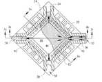
- FIG. 1is a top view of a prior art leadframe
- FIG. 1 ais a cross-sectional view of the prior art leadframe taken along line 1 a — 1 a of FIG. 1;
- FIG. 1 bis a cross-sectional view of the prior art leadframe taken along line 1 b — 1 b of FIG. 1;
- FIG. 1 cis a cross-sectional view of the prior art leadframe taken along line 1 c — 1 c of FIG. 1;
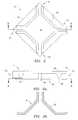
- FIG. 2is a bottom plan view of a prior art top mold in an encapsulation process during the manufacture of a semiconductor package
- FIG. 2 ais a cross-sectional view of the top mold of FIG. 2 taken along line 2 a — 2 a of FIG. 2;
- FIG. 2 bis a cross-sectional view of the top mold of FIG. 2 taken along line 2 b — 2 b of FIG. 2 a ;
- FIG. 3is a bottom view of the prior art top mold of FIG. 3 receiving encapsulating material during an encapsulation phase;
- FIG. 3 ais a cross-sectional view of the prior art top mold of FIG. 3 taken along line 3 a — 3 a of FIG. 3;
- FIG. 3 bis a cross-sectional view of the prior art top mold of FIG. 3 taken along line 3 b — 3 b of FIG. 3;
- FIG. 3 cis a cross-sectional view of the prior art top mold of FIG. 3 taken along line 3 c — 3 c of FIG. 3;
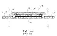
- FIG. 4 ais a cross-sectional view of prior art encapsulated semiconductor package encapsulated by the method shown in FIGS. 3 — 3 c;
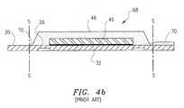
- FIG. 4 bis a cross-sectional view of prior art encapsulated semiconductor package encapsulated by the method shown in FIGS. 3-3 c;
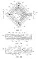
- FIG. 5is a top view of a leadframe of the invention.
- FIG. 5 ais a cross-sectional view of the leadframe of FIG. 5 taken along line 5 a — 5 a of FIG. 5;
- FIG. 5 bis a cross-sectional view of the leadframe of FIG. 5 taken along line 5 b — 5 b of FIG. 5;
- FIG. 6is a bottom view of a top mold of an embodiment of the present invention used in an encapsulation process during the manufacture of a semiconductor package;
- FIG. 6 ais a cross sectional view of the top mold of FIG. 6 taken along line 6 a — 6 a of FIG. 6;
- FIG. 6 bis a cross-sectional view of the top mold of FIG. 6 taken along line 6 b — 6 b of FIG. 6 a;
- FIG. 7is a partial cross-sectional view of the leadframe of FIG. 5 being clamped by the top mold of FIG. 6 during an encapsulation process;
- FIG. 7 ais a cross-sectional view of the leadframe and top mold of FIG. 7 taken along line 7 a — 7 a of FIG. 7 and of a bottom mold;
- FIG. 7 bis a cross-sectional view of the leadframe and top mold of FIG. 7 taken along line 7 b — 7 b of FIG. 7;
- FIG. 8is a cross-section view of an encapsulated semiconductor package of the invention undergoing singulation
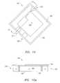
- FIG. 9is a top view of an alternative embodiment leadframe of the present invention.
- FIG. 10is a bottom view of an alternative embodiment top mold of the present invention.
- FIG. 10 ais a cross-sectional view of the top mold of FIG. 10;
- FIG. 11is a partial cross-sectional view of the leadframe of FIG. 9 being clamped by the top mold of FIG. 10 during an encapsulation process;
- FIG. 11 ais a cross-sectional view of the leadframe and top mold of FIG. 11 taken along line 11 a — 11 a of FIG. 11 and of a bottom mold.
- FIG. 1there is shown is a prior art leadframe 20 that has a plate type metal frame body 22 .
- many leadframesmay be formed in a larger frame body in a matrix form, e.g. the frame body described in U.S. patent application Ser. No. 09/176,614 which is commonly owned by assignee and which is hereby incorporated by reference.
- frame body 22is typically a small wafer of metal used in semiconductor package that may have a size on the order of 1 ⁇ 1 mm to 10 ⁇ 10 mm.
- these dimensionsare provided as examples only and other dimensions may be used.
- the prior art leadframe 20has a plurality of inner voids 24 , which define internal leads 26 .
- Leadframe 20additionally has a plurality of outer voids 28 .
- Outer voids 28define a plurality of external leads 30 .
- Inner voids 24define a chip paddle 32 , which is typically square.
- Adjacent inner voids 24define tie bars 34 , 36 , 38 and 40 , which communicate or make contact with chip paddle 32 with the portion of metal frame body 22 that is outside of inner voids 24 .
- the plurality of internal leads 26are offset from and surround the perimeter of chip paddle 32 .
- Dam bars 42are formed between the outer edge of inner voids 24 the inner edge of outer voids 28 . Dam bars 42 are provided to prevent molding material from flowing over the external leads 30 upon encapsulating.
- the dam bars 42 , external leads 30 , portions of tie bars 34 through 40 and the frame body 22are all removed in a singulation process.
- Leadframe 20has a groove 44 formed on its underside. Groove 44 can be seen in a cross section of FIG. 1, taken along line 1 a — 1 a , which is shown in FIG. 1 a . Additionally, groove 44 may be seen in FIG. 1 c , which is a cross sectional view taken along line 1 c — 1 c . Line 1 c — 1 c cuts through tie bars 36 and 40 .
- FIG. 1 bshows a cross sectional view of prior art leadframe 20 taken along lines 1 b — 1 b in FIG. 1 .
- Line 1 b — 1 bpasses through inner void 24 proximate tie bars 36 and 40 .
- a semiconductor chipTo form a semiconductor package, a semiconductor chip must be adhered to the leadframe 20 .
- a semiconductor chip(FIG. 4 a-c ) is mounted onto chip paddle 32 .
- the leadframe 20is positioned between a top mold 47 (FIGS. 2 a , 2 b , 3 a-c ) and a bottom mold (not shown) where the semiconductor chip 45 is encapsulated by an encapsulating material 46 .
- Top mold 47is designed to clamp onto dam bar 42 (FIG. 1) of the leadframe 20 and a portion of internal leads 26 (FIG. 1) with a sill 48 that protrudes down from the top mold plate 50 (FIG. 2 ).
- Sill 48forms a mold gate 52 and a plurality of mold vents 54 , 56 and 58 (FIG. 3 ). Mold gate 52 extends further outwardly than do mold vents 54 , 56 and 58 . Sill 48 surrounds a cavity 60 (FIGS. 2 and 2 a ) in which the semiconductor chip 45 (FIGS. 3 a - 3 c ) is encapsulated with encapsulation material 46 .
- a cross sectional view of top mold 47is shown in FIG. 2 a , which is taken along lines 2 a — 2 a of FIG. 2.
- a further cross sectional view shown in FIG. 2 bis taken along line 2 b — 2 b in FIG. 2 a and shows the sill contact surfaces 62 of sill 48 .
- FIGS. 3 through 3 cthe process of encapsulating the semiconductor chip with encapsulating material 46 is shown.
- Sill contact surface 62 of top mold 47is shown clamping leadframe 20 .
- Sill contact surface 62is positioned to clamp dam bars 42 and metal frame body 22 (FIG. 1 ).
- Encapsulating material 46is shown in FIG. 4, being introduced through mold gate 52 .
- Encapsulation material 46can be thermoplastics or thermoset resins, with thermoset resins including silicones, phenolics, and epoxies. Mold vents 54 , 56 and 58 allow discharge of gas and dregs of the encapsulation material 46 .
- the semiconductor chip 45is not shown in FIG. 3, but is visible in FIGS.
- FIGS. 3 a - 3 cshow semiconductor chip 45 being encapsulated by encapsulation material 46 .
- FIG. 3 ais a cross sectional view taken along lines 3 a — 3 a of FIG. 3 .
- encapsulation material 46can be seen surrounding semiconductor chip 45 and flowing through inner voids 24 into groove 44 .
- FIG. 3 bis a cross sectional view taken along lines 3 b — 3 b of FIG. 3 .
- Line 3 b — 3 bis a sectional line passing through the ends of internal voids 24 .
- the four-corner areas of leadframe 20are not clamped by the sill contact surfaces 62 of the top mold 47 .
- the encapsulating material 46flows through mold gate 52 , along the upper surface of the leadframe 20 , across tie bar 36 and into the cavity 60 . Gas and encapsulating material 46 escape through the mold vents 54 , 56 and 58 . The escape path for gas and encapsulating material may be seen in FIG. 3 .
- an encapsulated semiconductor package 68(FIG. 4 a ) is formed.
- Encapsulated semiconductor package 68is shown in a cross-sectional view similar to that seen in FIG. 3 b .
- Encapsulated semiconductor package 68may also be seen in FIG. 4 b which is a view similar to the cross-sectional view shown in FIG. 3 c .
- overflow encapsulation material, or flash 70is visible.
- Reference lines S—Sare provided to indicate where the singulation process acts upon the encapsulated semiconductor package 68 .
- the portion of flash 70 that is outside reference lines S—Smay be removed when the leadframe 20 is ejected from top mold 47 and the bottom mold.
- Flash 70 shown in FIGS. 5 a and 5 bis not uniform in thickness due to various factors such as molding pressure, molding period of time, temperature, etc.
- the flash 70 that is present inside of reference lines S—Smay cause problems during the singulation of leadframe 20 .
- the singulation processwill be explained in greater detail below.
- the flash 70is formed in the cavity 60 between the top mold 47 and the frame body 22 at locations of mold vents 54 , 56 and 58 . Gaps 71 are visible in FIGS. 3 b and 3 c.
- FIG. 6shows a leadframe 120 that has a plate type metal frame body 122 . Portions of metal frame body 122 are removed from the frame body 122 , which create a plurality of voids therein.
- Leadframe 120has a plurality of inner voids 124 having elongated ends 125 as compared to prior art inner voids 24 (FIG. 1 ).
- Leadframe 120additionally has a plurality of outer voids 128 formed therein. Outer voids 128 define a plurality of external leads 130 .
- Inner voids 124define a chip paddle 132 , which is typically square.
- Adjacent inner voids 124define tie bars 134 , 136 , 138 and 140 , which communicate chip paddle 132 with the portion of metal frame body 122 that is outside of inner voids 124 .
- the plurality of internal leads 126are offset from and surround the perimeter of chip paddle 132 .
- Dam bars 142are formed between the outer edge of inner voids 124 the inner edge of outer voids 128 . Dam bars 142 are provided to prevent a molding material from flowing over the external leads 130 upon encapsulating.
- Elongated ends 125extend beyond dam bars 142 toward the corners of leadframe 120 .
- Leadframe 120has a groove 144 formed on its underside. Groove 144 can be seen in the cross section in FIG.
- FIG. 5 bwhich is a cross sectional view of FIG. 5 taken along line 5 b — 5 b .
- Line 5 b — 5 bcuts through tie bars 136 and 140 .
- Groove 144can be seen passing beneath tie bars 136 and 140 of FIG. 5 b .
- FIG. 5 ashows a cross sectional view of leadframe 120 taken along lines 5 a — 5 a of FIG. 5 .
- Line 5 a — 5 apasses through inner void 124 proximate tie bars 136 and 140 .
- chip paddle 132 and leadframe 120are positioned between a top mold 146 (FIG. 6) and a bottom mold 149 (FIGS. 7 a and 7 b ) and encapsulated by an encapsulating material 147 (FIGS. 7, 7 a and 7 b ).
- Encapsulating material 147can be thermoset plastics or thermoset resins, with thermoset resins including silicones, phenolics, and epoxies.
- Top mold 146is designed to clamp the dam bar 142 of the leadframe 120 and part of the internal leads 126 (FIG.
- Sill 148forms a mold gate 152 and a plurality of mold vents 154 , 156 and 158 .
- Sill 148forms a cavity 160 (FIGS. 6 and 6 a ) in which the semiconductor chip 145 , wires, etc., are encapsulated with the encapsulation material 147 .
- a cross sectional view of cavity 160can be seen in FIG. 6 a , which is taken along lines 6 a — 6 a of FIG. 6 .
- FIG. 6 bis a cross-sectional view of FIG. 6 a taken along line 6 b — 6 b in FIG. 6 a .
- Sill 148has a tetragonal shape and is chamfered in the area of the bars 134 - 140 .
- FIG. 6 bshows sill contact surfaces 162 of sill 148 .
- FIGS. 7 through 7 bthe process of encapsulating the semiconductor chip 145 with encapsulating material 147 is shown.
- Leadframe 120is shown being clamped by sill contact surface 162 of top mold 146 .
- Sill contact surface 162is positioned to apply clamping pressure to dam bars 142 and metal frame body 122 .
- Encapsulating material 147is shown being introduced through mold gate 152 .
- Mold vents 154 , 156 and 158allow discharge of gas and dregs of the encapsulation material 164 .
- the semiconductor chip 145is not shown in FIG. 7 . However, semiconductor chip 145 is visible in FIGS. 7 a and 7 b , where it is shown being encapsulated by encapsulation material 147 .
- FIG. 7 ais a cross sectional view taken along lines 7 a — 7 a of FIG. 7 .
- encapsulation material 147can be seen surrounding semiconductor chip 145 .
- FIG. 7 bis a cross sectional view taken along lines 7 b — 7 b of FIG. 7 .
- Line 7 b — 7 bcrosses through elongated ends 125 of inner voids 124 .
- encapsulation material 147When encapsulation material 147 enters through mold gate 152 , the encapsulation material 147 must pass below sill 148 (see FIG. 7 and 7 b ) before entering cavity 160 Gas that is to be vented is allowed to pass through small openings 163 (FIGS. 7 a & 7 b ) in mold vents 154 , 156 and 158 . However, since the openings 163 are small and substantially restrict flow of encapsulation material 147 , the occurrence of flash is reduced.
- FIG. 7 btaken along the line 7 b — 7 b of FIG. 7, the encapsulating material 147 is shown flowing through elongated ends 125 of inner voids 124 under sill 148 and into cavity 160 .
- molding material gas, air and molding material flashare also discharged through to the outside. Therefore, no molding material flashes remain on the upper surfaces of the tie bars 134 - 140 which are brought into close contact with the sill 148 of the top mold 146 .
- an encapsulated semiconductor package 168(FIG. 8) is formed.
- Encapsulated semiconductor package 168is shown in the cross-sectional view similar to that shown in prior art FIG. 3 c .
- the encapsulated semiconductor package 168is shown in FIG. 8 undergoing a singulation process.
- the encapsulated semiconductor package 168is undergoing the encapsulation process and is strongly clamped between the top clamp 170 and the bottom clamp 172 .
- the absence of the molding material flash on the leadframe 120 in the tie bar areaenables the leadframe 120 to be accurately brought into close contact with the top clamp 170 and the bottom clamp 172 . Therefore, the dam bars and the tie bars all can be clamped with uniform force.
- a singulation tool 174is allowed to cut the dam bars and the tie bars with uniform force. Without being damaged, the package body 176 is isolated into an individual unit.
- FIG. 9shows a leadframe 220 that has a plate type metal frame body 222 . Portions of metal frame body 222 are removed from the metal frame body 222 , which create a plurality of voids therein.
- Leadframe 220has two large inner voids 224 .
- Inner voids 224define internal leads 226 .
- Leadframe 220additionally has a plurality of outer voids 228 formed therein.
- Outer voids 228define a plurality of external leads 230 .
- Inner voids 224define a chip paddle 232 .
- the two inner voids 224define tie bars 234 and 236 , which communicate chip paddle 232 with the portion of metal frame body 222 that is outside of inner voids 224 .
- the plurality of internal leads 226are offset from and surround the perimeter of chip paddle 232 .
- Dam bars 242are formed between the outer edge of inner voids 224 the inner edge of outer voids 228 . Dam bars 242 are provided to prevent a molding material from flowing over the external leads 230 upon encapsulating.
- chip paddle 232 and leadframe 220are positioned between a top mold 246 (FIGS. 10 and 10 a ) and a bottom mold 249 and encapsulated by an encapsulating material 247 (FIG. 11 ).
- Encapsulating material 247can be thermoplastics or thermoset resins, with thermoset resins including silicones, phenolics, and epoxies.
- Top mold 246is designed to clamp the dam bar 242 of the leadframe 220 and part of the internal leads 226 with a sill 248 , which protrudes down from the top mold plate 250 .
- Sill 248forms a mold gate 252 and a plurality of mold vents 254 and 256 .
- Sill 248forms a cavity 260 (FIGS. 10 and 10 a ) in which the semiconductor chip, wires, etc., are encapsulated with the encapsulation material 247 .
- FIG. 11the process of encapsulating a semiconductor chip 245 with encapsulating material 247 is shown.
- Leadframe 220is shown being clamped by sill 248 of top mold 246 .
- Sill 248is positioned to apply clamping pressure to dam bars and metal frame body.
- Encapsulating material 247is shown being introduced through mold gate 252 . Mold vents 254 and 256 allow for discharge of gas, as well as dregs, of the encapsulation material 264 .
- the semiconductor chip 245is not shown in FIG. 11 . However, semiconductor chip 245 is visible in FIG. 11 a , where it is shown being encapsulated by encapsulation material 247 .
- FIG. 11 ais a cross sectional view taken along lines 11 a — 11 a of FIG. 11 . In FIG. 11 a , encapsulation material 247 can be seen surrounding semiconductor chip 245 .
- FIG. 11 ataken along the line 11 a — 11 a of FIG. 11, the encapsulating material 247 is shown flowing through one of inner voids 224 under sill 248 and into cavity 260 .
- molding material gas, air and molding material flashare also discharged through mold vent 254 to the outside. Therefore, no molding material flash remains on the upper surfaces of the tie bars 234 and 236 , which are brought into close contact with the sill 248 of the top mold 246 .
- the leadframewhen the leadframe is subjected to singulation after the encapsulation, no flash is found in the leadframe area of the singulation, i.e. in the areas of the dam bars and tie bars.
- the entire leadframecan be clamped with uniform force, resulting in a smooth singulation operation and preventing the chip-out phenomenon.
- the sill of the top moldclamps the dam bars as well as the tie bars, so that the chip paddle is prevented from being tilted or floated by pressure of the molding material and thus, no flashes remain on the bottom surface of the chip paddle.
Landscapes
- Engineering & Computer Science (AREA)
- Computer Hardware Design (AREA)
- Microelectronics & Electronic Packaging (AREA)
- Power Engineering (AREA)
- Physics & Mathematics (AREA)
- Condensed Matter Physics & Semiconductors (AREA)
- General Physics & Mathematics (AREA)
- Geometry (AREA)
- Manufacturing & Machinery (AREA)
- Encapsulation Of And Coatings For Semiconductor Or Solid State Devices (AREA)
Abstract
Description
| Application | First Named | |
| Number | Title of Application | Inventor |
| 09/687,787 | Thin and Heat Radiant Semi- | Jae Hun Ku |
| conductor Package and Method for | ||
| Manufacturing | ||
| 09/687,532 | Method for Making a Semi- | Tae Heon Lee |
| conductor Package Having | ||
| Improved Defect Testing and | ||
| Increased Production Yield | ||
| 09/687,876 | Near Chip Size Semiconductor | Sean Timothy Crowley |
| Package | ||
| 09/687,536 | End Grid Array Semiconductor | Jae Hun Ku |
| Package | ||
| 09/687,048 | Leadframe and Semiconductor | Tae Heon Lee |
| Package with Improved Solder | ||
| Joint Strength | ||
| 09/687,585 | Semiconductor Package Having | Tae Heon Lee |
| Reduced Thickness | ||
| 09/687,541 | Semiconductor Package Leadframe | Young Suk Chung |
| Assembly and Method of | ||
| Manufacture | ||
| 09/687,049 | Improved Method for Making | Young Suk Chung |
| Semiconductor Packages | ||
Claims (20)
Applications Claiming Priority (2)
| Application Number | Priority Date | Filing Date | Title |
|---|---|---|---|
| KR1019990044646AKR100355796B1 (en) | 1999-10-15 | 1999-10-15 | structure of leadframe for semiconductor package and mold for molding the same |
| KR99-44646 | 1999-10-15 |
Publications (1)
| Publication Number | Publication Date |
|---|---|
| US6627976B1true US6627976B1 (en) | 2003-09-30 |
Family
ID=19615429
Family Applications (1)
| Application Number | Title | Priority Date | Filing Date |
|---|---|---|---|
| US09/687,331Expired - LifetimeUS6627976B1 (en) | 1999-10-15 | 2000-10-13 | Leadframe for semiconductor package and mold for molding the same |
Country Status (2)
| Country | Link |
|---|---|
| US (1) | US6627976B1 (en) |
| KR (1) | KR100355796B1 (en) |
Cited By (31)
| Publication number | Priority date | Publication date | Assignee | Title |
|---|---|---|---|---|
| US20030087478A1 (en)* | 2000-08-18 | 2003-05-08 | Hitachi, Ltd. | Semiconductor device and a method of manufacturing the same |
| US20030234446A1 (en)* | 2002-02-20 | 2003-12-25 | Stmicroelectronics Sa | Flat leadframe for a semiconductor package |
| US20040018663A1 (en)* | 2002-07-26 | 2004-01-29 | Mitsubishi Denki Kabushiki Kaisha | .Lead frame, and method for manufacturing semiconductor device and method for inspecting electrical properties of small device using the lead frame |
| US20040080026A1 (en)* | 2002-10-24 | 2004-04-29 | Matsushita Electric Industrial Co., Ltd. | Leadframe, plastic-encapsulated semiconductor device, and method for fabricating the same |
| US6876068B1 (en)* | 2002-09-09 | 2005-04-05 | Amkor Technology, Inc | Semiconductor package with increased number of input and output pins |
| US20050186711A1 (en)* | 2004-02-20 | 2005-08-25 | Yee Richard M.L. | Mould for encapsulating a leadframe package and method of making the same |
| US20060181861A1 (en)* | 2005-02-17 | 2006-08-17 | Walker Harold Y Jr | Etched leadframe for reducing metal gaps |
| US20060234426A1 (en)* | 2005-04-14 | 2006-10-19 | Stats Chippac Ltd. | Leadframe with encapsulant guide and method for the fabrication thereof |
| US20060267163A1 (en)* | 2004-07-21 | 2006-11-30 | Linear Technology Corporation | Flashless lead frame with horizontal singulation |
| US20070004092A1 (en)* | 2003-08-29 | 2007-01-04 | Hiromichi Suzuki | Semiconductor device manufacturing method |
| US7166496B1 (en) | 2005-08-17 | 2007-01-23 | Ciclon Semiconductor Device Corp. | Method of making a packaged semiconductor device |
| US20070085204A1 (en)* | 2005-10-19 | 2007-04-19 | Cicion Semiconductor Device Corp. | Chip scale power LDMOS device |
| US20070215939A1 (en)* | 2006-03-14 | 2007-09-20 | Shuming Xu | Quasi-vertical LDMOS device having closed cell layout |
| US20080036078A1 (en)* | 2006-08-14 | 2008-02-14 | Ciclon Semiconductor Device Corp. | Wirebond-less semiconductor package |
| US20080237816A1 (en)* | 2007-03-30 | 2008-10-02 | Henry Descalzo Bathan | Integrated circuit package system with encapsulating features |
| US20090174055A1 (en)* | 2000-06-09 | 2009-07-09 | Vishay-Siliconix | Leadless Semiconductor Packages |
| US7612436B1 (en) | 2008-07-31 | 2009-11-03 | Micron Technology, Inc. | Packaged microelectronic devices with a lead frame |
| US20100044844A1 (en)* | 2008-08-22 | 2010-02-25 | Sumitomo Chemical Company, Limited | Lead frame, resin package, semiconductor device and resin package manufacturing method |
| US20100176508A1 (en)* | 2009-01-12 | 2010-07-15 | Ciclon Semiconductor Device Corp. | Semiconductor device package and method of assembly thereof |
| US20100227436A1 (en)* | 2008-03-04 | 2010-09-09 | Infineon Technologies Ag | Method of fabricating a semiconductor package with mold lock opening |
| US20130154079A1 (en)* | 2011-12-14 | 2013-06-20 | Oh Han Kim | Integrated circuit packaging system with substrate mold gate and method of manufacture thereof |
| US8588017B2 (en) | 2010-10-20 | 2013-11-19 | Samsung Electronics Co., Ltd. | Memory circuits, systems, and modules for performing DRAM refresh operations and methods of operating the same |
| CN104795377A (en)* | 2014-01-17 | 2015-07-22 | 飞思卡尔半导体公司 | Semiconductor device with lead webbings |
| CN104838494A (en)* | 2013-12-05 | 2015-08-12 | 新电元工业株式会社 | Lead frame, molding die, and method for manufacturing mounting component-attached lead frame |
| US20150364456A1 (en)* | 2014-06-12 | 2015-12-17 | Taiwan Semiconductor Manufacturing Company, Ltd. | Wafer-level molding chase design |
| US9443746B2 (en) | 2014-08-15 | 2016-09-13 | Freescale Semiconductor, Inc. | Floating mold tool for semicondcutor packaging |
| US9881814B2 (en) | 2015-02-12 | 2018-01-30 | Samsung Electronics Co., Ltd. | Apparatus for manufacturing semiconductor package and method for manufacturing semiconductor package using the same |
| US10373887B2 (en) | 2017-09-15 | 2019-08-06 | Samsung Electronics Co., Ltd. | Fan-out semiconductor package |
| US20190348348A1 (en)* | 2000-10-06 | 2019-11-14 | Rohm Co., Ltd. | Semiconductor device with lead terminals having portions thereof extending obliquely |
| CN113421871A (en)* | 2021-07-21 | 2021-09-21 | 强茂电子(无锡)有限公司 | Improvement type DFN lead frame |
| US11942383B2 (en) | 2020-11-09 | 2024-03-26 | Infineon Technologies Ag | Linear spacer for spacing a carrier of a package |
Families Citing this family (3)
| Publication number | Priority date | Publication date | Assignee | Title |
|---|---|---|---|---|
| KR100559551B1 (en)* | 2003-10-11 | 2006-03-15 | 앰코 테크놀로지 코리아 주식회사 | Lead frame for semiconductor device, encapsulation mold and encapsulation method |
| KR100646495B1 (en)* | 2005-09-14 | 2006-11-14 | 앰코 테크놀로지 코리아 주식회사 | Lead frame and mold for sealing it |
| KR20170051085A (en) | 2015-11-02 | 2017-05-11 | 삼성전자주식회사 | Embedded refresh controller and memory device including the same |
Citations (43)
| Publication number | Priority date | Publication date | Assignee | Title |
|---|---|---|---|---|
| US4289922A (en)* | 1979-09-04 | 1981-09-15 | Plessey Incorporated | Integrated circuit package and lead frame |
| JPS5745959A (en) | 1980-09-02 | 1982-03-16 | Nec Corp | Resin-sealed semiconductor device |
| JPS58101317A (en) | 1981-12-14 | 1983-06-16 | Koike Sanso Kogyo Co Ltd | Rotating positioning device of positioner |
| JPS58160095A (en) | 1982-03-12 | 1983-09-22 | 明産株式会社 | Slitter device automatically positioning slitter knife |
| US4530152A (en) | 1982-04-01 | 1985-07-23 | Compagnie Industrielle Des Telecommunications Cit-Alcatel | Method for encapsulating semiconductor components using temporary substrates |
| JPS6139555A (en) | 1984-07-31 | 1986-02-25 | Toshiba Corp | Resin sealed type semiconductor device with heat sink |
| JPS629639A (en) | 1985-07-05 | 1987-01-17 | Nec Yamagata Ltd | Manufacture of semiconductor device |
| JPS63205935A (en) | 1987-02-23 | 1988-08-25 | Toshiba Corp | Resin-encapsulated semiconductor device with heat sink |
| JPS63233555A (en) | 1987-03-23 | 1988-09-29 | Toshiba Corp | Resin-encapsulated semiconductor device |
| JPS6454749A (en) | 1987-08-26 | 1989-03-02 | Matsushita Electric Industrial Co Ltd | Semiconductor device and manufacture thereof |
| US5041902A (en) | 1989-12-14 | 1991-08-20 | Motorola, Inc. | Molded electronic package with compression structures |
| KR920010286A (en) | 1990-11-19 | 1992-06-26 | 존 디. 후써 | A device to shuttle test elements from the discharge path to the cleaning station |
| US5157480A (en) | 1991-02-06 | 1992-10-20 | Motorola, Inc. | Semiconductor device having dual electrical contact sites |
| US5172213A (en) | 1991-05-23 | 1992-12-15 | At&T Bell Laboratories | Molded circuit package having heat dissipating post |
| US5172214A (en) | 1991-02-06 | 1992-12-15 | Motorola, Inc. | Leadless semiconductor device and method for making the same |
| US5278446A (en) | 1992-07-06 | 1994-01-11 | Motorola, Inc. | Reduced stress plastic package |
| US5424576A (en)* | 1993-03-22 | 1995-06-13 | Motorola, Inc. | Semiconductor device having x-shaped die support member and method for making the same |
| US5428248A (en) | 1992-08-21 | 1995-06-27 | Goldstar Electron Co., Ltd. | Resin molded semiconductor package |
| JPH07312405A (en) | 1994-05-17 | 1995-11-28 | Hitachi Ltd | Semiconductor device |
| KR960009774A (en) | 1994-08-06 | 1996-03-22 | 김광호 | Clock fault detection circuit of all electronic switch |
| US5517056A (en)* | 1993-09-30 | 1996-05-14 | Motorola, Inc. | Molded carrier ring leadframe having a particular resin injecting area design for gate removal and semiconductor device employing the same |
| JPH08125066A (en) | 1994-10-26 | 1996-05-17 | Dainippon Printing Co Ltd | Resin-sealed semiconductor device, lead frame used therefor, and method of manufacturing resin-sealed semiconductor device |
| US5521429A (en) | 1993-11-25 | 1996-05-28 | Sanyo Electric Co., Ltd. | Surface-mount flat package semiconductor device |
| JPH08306853A (en) | 1995-05-09 | 1996-11-22 | Fujitsu Ltd | Semiconductor device, method of manufacturing the same, and method of manufacturing lead frame |
| JPH098205A (en) | 1995-06-14 | 1997-01-10 | Dainippon Printing Co Ltd | Resin-sealed semiconductor device |
| JPH098206A (en) | 1995-06-19 | 1997-01-10 | Dainippon Printing Co Ltd | Lead frame and bga resin sealed semiconductor device |
| JPH098207A (en) | 1995-06-21 | 1997-01-10 | Dainippon Printing Co Ltd | Resin-sealed semiconductor device |
| US5594274A (en)* | 1993-07-01 | 1997-01-14 | Nec Corporation | Lead frame for use in a semiconductor device and method of manufacturing the semiconductor device using the same |
| JPH0992775A (en) | 1995-09-22 | 1997-04-04 | Hitachi Cable Ltd | Semiconductor device |
| US5633528A (en)* | 1994-05-25 | 1997-05-27 | Texas Instruments Incorporated | Lead frame structure for IC devices with strengthened encapsulation adhesion |
| US5701034A (en) | 1994-05-03 | 1997-12-23 | Amkor Electronics, Inc. | Packaged semiconductor die including heat sink with locking feature |
| US5783861A (en) | 1994-03-29 | 1998-07-21 | Lg Semicon Co., Ltd. | Semiconductor package and lead frame |
| US5835988A (en) | 1996-03-27 | 1998-11-10 | Mitsubishi Denki Kabushiki Kaisha | Packed semiconductor device with wrap around external leads |
| US5866939A (en) | 1996-01-21 | 1999-02-02 | Anam Semiconductor Inc. | Lead end grid array semiconductor package |
| US5894108A (en) | 1997-02-11 | 1999-04-13 | National Semiconductor Corporation | Plastic package with exposed die |
| US5977613A (en) | 1996-03-07 | 1999-11-02 | Matsushita Electronics Corporation | Electronic component, method for making the same, and lead frame and mold assembly for use therein |
| US5977630A (en) | 1997-08-15 | 1999-11-02 | International Rectifier Corp. | Plural semiconductor die housed in common package with split heat sink |
| US6143981A (en) | 1998-06-24 | 2000-11-07 | Amkor Technology, Inc. | Plastic integrated circuit package and method and leadframe for making the package |
| US6201186B1 (en)* | 1998-06-29 | 2001-03-13 | Motorola, Inc. | Electronic component assembly and method of making the same |
| US6229200B1 (en) | 1998-06-10 | 2001-05-08 | Asat Limited | Saw-singulated leadless plastic chip carrier |
| US6291273B1 (en)* | 1996-12-26 | 2001-09-18 | Hitachi, Ltd. | Plastic molded type semiconductor device and fabrication process thereof |
| US6294100B1 (en) | 1998-06-10 | 2001-09-25 | Asat Ltd | Exposed die leadless plastic chip carrier |
| US6355502B1 (en) | 2000-04-25 | 2002-03-12 | National Science Council | Semiconductor package and method for making the same |
- 1999
- 1999-10-15KRKR1019990044646Apatent/KR100355796B1/ennot_activeExpired - Fee Related
- 2000
- 2000-10-13USUS09/687,331patent/US6627976B1/ennot_activeExpired - Lifetime
Patent Citations (44)
| Publication number | Priority date | Publication date | Assignee | Title |
|---|---|---|---|---|
| US4289922A (en)* | 1979-09-04 | 1981-09-15 | Plessey Incorporated | Integrated circuit package and lead frame |
| JPS5745959A (en) | 1980-09-02 | 1982-03-16 | Nec Corp | Resin-sealed semiconductor device |
| JPS58101317A (en) | 1981-12-14 | 1983-06-16 | Koike Sanso Kogyo Co Ltd | Rotating positioning device of positioner |
| JPS58160095A (en) | 1982-03-12 | 1983-09-22 | 明産株式会社 | Slitter device automatically positioning slitter knife |
| US4530152A (en) | 1982-04-01 | 1985-07-23 | Compagnie Industrielle Des Telecommunications Cit-Alcatel | Method for encapsulating semiconductor components using temporary substrates |
| JPS6139555A (en) | 1984-07-31 | 1986-02-25 | Toshiba Corp | Resin sealed type semiconductor device with heat sink |
| JPS629639A (en) | 1985-07-05 | 1987-01-17 | Nec Yamagata Ltd | Manufacture of semiconductor device |
| JPS63205935A (en) | 1987-02-23 | 1988-08-25 | Toshiba Corp | Resin-encapsulated semiconductor device with heat sink |
| JPS63233555A (en) | 1987-03-23 | 1988-09-29 | Toshiba Corp | Resin-encapsulated semiconductor device |
| JPS6454749A (en) | 1987-08-26 | 1989-03-02 | Matsushita Electric Industrial Co Ltd | Semiconductor device and manufacture thereof |
| US5041902A (en) | 1989-12-14 | 1991-08-20 | Motorola, Inc. | Molded electronic package with compression structures |
| KR920010286A (en) | 1990-11-19 | 1992-06-26 | 존 디. 후써 | A device to shuttle test elements from the discharge path to the cleaning station |
| US5157480A (en) | 1991-02-06 | 1992-10-20 | Motorola, Inc. | Semiconductor device having dual electrical contact sites |
| US5172214A (en) | 1991-02-06 | 1992-12-15 | Motorola, Inc. | Leadless semiconductor device and method for making the same |
| US5172213A (en) | 1991-05-23 | 1992-12-15 | At&T Bell Laboratories | Molded circuit package having heat dissipating post |
| US5278446A (en) | 1992-07-06 | 1994-01-11 | Motorola, Inc. | Reduced stress plastic package |
| US5428248A (en) | 1992-08-21 | 1995-06-27 | Goldstar Electron Co., Ltd. | Resin molded semiconductor package |
| US5424576A (en)* | 1993-03-22 | 1995-06-13 | Motorola, Inc. | Semiconductor device having x-shaped die support member and method for making the same |
| US5594274A (en)* | 1993-07-01 | 1997-01-14 | Nec Corporation | Lead frame for use in a semiconductor device and method of manufacturing the semiconductor device using the same |
| US5517056A (en)* | 1993-09-30 | 1996-05-14 | Motorola, Inc. | Molded carrier ring leadframe having a particular resin injecting area design for gate removal and semiconductor device employing the same |
| US5521429A (en) | 1993-11-25 | 1996-05-28 | Sanyo Electric Co., Ltd. | Surface-mount flat package semiconductor device |
| US5783861A (en) | 1994-03-29 | 1998-07-21 | Lg Semicon Co., Ltd. | Semiconductor package and lead frame |
| US5701034A (en) | 1994-05-03 | 1997-12-23 | Amkor Electronics, Inc. | Packaged semiconductor die including heat sink with locking feature |
| JPH07312405A (en) | 1994-05-17 | 1995-11-28 | Hitachi Ltd | Semiconductor device |
| US5633528A (en)* | 1994-05-25 | 1997-05-27 | Texas Instruments Incorporated | Lead frame structure for IC devices with strengthened encapsulation adhesion |
| KR960009774A (en) | 1994-08-06 | 1996-03-22 | 김광호 | Clock fault detection circuit of all electronic switch |
| JPH08125066A (en) | 1994-10-26 | 1996-05-17 | Dainippon Printing Co Ltd | Resin-sealed semiconductor device, lead frame used therefor, and method of manufacturing resin-sealed semiconductor device |
| JPH08306853A (en) | 1995-05-09 | 1996-11-22 | Fujitsu Ltd | Semiconductor device, method of manufacturing the same, and method of manufacturing lead frame |
| JPH098205A (en) | 1995-06-14 | 1997-01-10 | Dainippon Printing Co Ltd | Resin-sealed semiconductor device |
| JPH098206A (en) | 1995-06-19 | 1997-01-10 | Dainippon Printing Co Ltd | Lead frame and bga resin sealed semiconductor device |
| JPH098207A (en) | 1995-06-21 | 1997-01-10 | Dainippon Printing Co Ltd | Resin-sealed semiconductor device |
| JPH0992775A (en) | 1995-09-22 | 1997-04-04 | Hitachi Cable Ltd | Semiconductor device |
| US5866939A (en) | 1996-01-21 | 1999-02-02 | Anam Semiconductor Inc. | Lead end grid array semiconductor package |
| US5977613A (en) | 1996-03-07 | 1999-11-02 | Matsushita Electronics Corporation | Electronic component, method for making the same, and lead frame and mold assembly for use therein |
| US5835988A (en) | 1996-03-27 | 1998-11-10 | Mitsubishi Denki Kabushiki Kaisha | Packed semiconductor device with wrap around external leads |
| US6291273B1 (en)* | 1996-12-26 | 2001-09-18 | Hitachi, Ltd. | Plastic molded type semiconductor device and fabrication process thereof |
| US5894108A (en) | 1997-02-11 | 1999-04-13 | National Semiconductor Corporation | Plastic package with exposed die |
| US5977630A (en) | 1997-08-15 | 1999-11-02 | International Rectifier Corp. | Plural semiconductor die housed in common package with split heat sink |
| US6242281B1 (en) | 1998-06-10 | 2001-06-05 | Asat, Limited | Saw-singulated leadless plastic chip carrier |
| US6229200B1 (en) | 1998-06-10 | 2001-05-08 | Asat Limited | Saw-singulated leadless plastic chip carrier |
| US6294100B1 (en) | 1998-06-10 | 2001-09-25 | Asat Ltd | Exposed die leadless plastic chip carrier |
| US6143981A (en) | 1998-06-24 | 2000-11-07 | Amkor Technology, Inc. | Plastic integrated circuit package and method and leadframe for making the package |
| US6201186B1 (en)* | 1998-06-29 | 2001-03-13 | Motorola, Inc. | Electronic component assembly and method of making the same |
| US6355502B1 (en) | 2000-04-25 | 2002-03-12 | National Science Council | Semiconductor package and method for making the same |
Cited By (64)
| Publication number | Priority date | Publication date | Assignee | Title |
|---|---|---|---|---|
| US8928157B2 (en)* | 2000-06-09 | 2015-01-06 | Vishay-Siliconix | Encapsulation techniques for leadless semiconductor packages |
| US20090174055A1 (en)* | 2000-06-09 | 2009-07-09 | Vishay-Siliconix | Leadless Semiconductor Packages |
| US20040104490A1 (en)* | 2000-08-18 | 2004-06-03 | Hitachi, Ltd. | Semiconductor device and a method of manufacturing the same |
| US6800507B2 (en) | 2000-08-18 | 2004-10-05 | Renesas Technology Corp. | Semiconductor device and a method of manufacturing the same |
| US20030087478A1 (en)* | 2000-08-18 | 2003-05-08 | Hitachi, Ltd. | Semiconductor device and a method of manufacturing the same |
| US6897093B2 (en) | 2000-08-18 | 2005-05-24 | Renesas Technology Corp. | Method of manufacturing a resin molded or encapsulation for small outline non-leaded (SON) or quad flat non-leaded (QFN) package |
| US10886204B2 (en)* | 2000-10-06 | 2021-01-05 | Rohm Co., Ltd. | Semiconductor device with lead terminals having portions thereof extending obliquely |
| US20190348348A1 (en)* | 2000-10-06 | 2019-11-14 | Rohm Co., Ltd. | Semiconductor device with lead terminals having portions thereof extending obliquely |
| US20030234446A1 (en)* | 2002-02-20 | 2003-12-25 | Stmicroelectronics Sa | Flat leadframe for a semiconductor package |
| US6885088B2 (en)* | 2002-02-20 | 2005-04-26 | Stmicroelectronics Sa | Flat leadframe for a semiconductor package |
| US6836004B2 (en)* | 2002-07-26 | 2004-12-28 | Renesas Technology Corp. | Lead frame, and method for manufacturing semiconductor device and method for inspecting electrical properties of small device using the lead frame |
| US20040018663A1 (en)* | 2002-07-26 | 2004-01-29 | Mitsubishi Denki Kabushiki Kaisha | .Lead frame, and method for manufacturing semiconductor device and method for inspecting electrical properties of small device using the lead frame |
| US6876068B1 (en)* | 2002-09-09 | 2005-04-05 | Amkor Technology, Inc | Semiconductor package with increased number of input and output pins |
| US20050236701A1 (en)* | 2002-10-24 | 2005-10-27 | Matsushita Electric Industrial Co., Ltd. | Leadframe, plastic-encapsulated semiconductor device, and method for fabricating the same |
| US7042071B2 (en)* | 2002-10-24 | 2006-05-09 | Matsushita Electric Industrial Co., Ltd. | Leadframe, plastic-encapsulated semiconductor device, and method for fabricating the same |
| US7132315B2 (en) | 2002-10-24 | 2006-11-07 | Matsushita Electric Industrial Co., Ltd. | Leadframe, plastic-encapsulated semiconductor device, and method for fabricating the same |
| US20040080026A1 (en)* | 2002-10-24 | 2004-04-29 | Matsushita Electric Industrial Co., Ltd. | Leadframe, plastic-encapsulated semiconductor device, and method for fabricating the same |
| US20070004092A1 (en)* | 2003-08-29 | 2007-01-04 | Hiromichi Suzuki | Semiconductor device manufacturing method |
| US7351611B2 (en) | 2004-02-20 | 2008-04-01 | Carsem (M) Sdn Bhd | Method of making the mould for encapsulating a leadframe package |
| US20050186711A1 (en)* | 2004-02-20 | 2005-08-25 | Yee Richard M.L. | Mould for encapsulating a leadframe package and method of making the same |
| US7414302B2 (en)* | 2004-07-21 | 2008-08-19 | Linear Technology Corporation | Flashless lead frame with horizontal singulation |
| US20060267163A1 (en)* | 2004-07-21 | 2006-11-30 | Linear Technology Corporation | Flashless lead frame with horizontal singulation |
| US20060181861A1 (en)* | 2005-02-17 | 2006-08-17 | Walker Harold Y Jr | Etched leadframe for reducing metal gaps |
| US20060234426A1 (en)* | 2005-04-14 | 2006-10-19 | Stats Chippac Ltd. | Leadframe with encapsulant guide and method for the fabrication thereof |
| US7338841B2 (en)* | 2005-04-14 | 2008-03-04 | Stats Chippac Ltd. | Leadframe with encapsulant guide and method for the fabrication thereof |
| US7166496B1 (en) | 2005-08-17 | 2007-01-23 | Ciclon Semiconductor Device Corp. | Method of making a packaged semiconductor device |
| US7504733B2 (en) | 2005-08-17 | 2009-03-17 | Ciclon Semiconductor Device Corp. | Semiconductor die package |
| US20070040254A1 (en)* | 2005-08-17 | 2007-02-22 | Lopez Osvaldo J | Semiconductor die package |
| US20070085204A1 (en)* | 2005-10-19 | 2007-04-19 | Cicion Semiconductor Device Corp. | Chip scale power LDMOS device |
| US7560808B2 (en) | 2005-10-19 | 2009-07-14 | Texas Instruments Incorporated | Chip scale power LDMOS device |
| US7446375B2 (en) | 2006-03-14 | 2008-11-04 | Ciclon Semiconductor Device Corp. | Quasi-vertical LDMOS device having closed cell layout |
| US20070215939A1 (en)* | 2006-03-14 | 2007-09-20 | Shuming Xu | Quasi-vertical LDMOS device having closed cell layout |
| US20080036078A1 (en)* | 2006-08-14 | 2008-02-14 | Ciclon Semiconductor Device Corp. | Wirebond-less semiconductor package |
| US20110095411A1 (en)* | 2006-08-14 | 2011-04-28 | Texas Instruments Incorporated | Wirebond-less Semiconductor Package |
| US8304903B2 (en) | 2006-08-14 | 2012-11-06 | Texas Instruments Incorporated | Wirebond-less semiconductor package |
| US20080237816A1 (en)* | 2007-03-30 | 2008-10-02 | Henry Descalzo Bathan | Integrated circuit package system with encapsulating features |
| US8207600B2 (en)* | 2007-03-30 | 2012-06-26 | Stats Chippac Ltd. | Integrated circuit package system with encapsulating features |
| US20100227436A1 (en)* | 2008-03-04 | 2010-09-09 | Infineon Technologies Ag | Method of fabricating a semiconductor package with mold lock opening |
| US8466009B2 (en)* | 2008-03-04 | 2013-06-18 | Infineon Technologies Ag | Method of fabricating a semiconductor package with mold lock opening |
| US20100029043A1 (en)* | 2008-07-31 | 2010-02-04 | Micron Technology, Inc. | Packaged microelectronic devices and methods for manufacturing packaged microelectronic devices |
| US8283761B2 (en) | 2008-07-31 | 2012-10-09 | Micron Technology, Inc. | Packaged microelectronic devices and methods for manufacturing packaged microelectronic devices |
| US7968376B2 (en) | 2008-07-31 | 2011-06-28 | Micron Technology, Inc. | Packaged microelectronic devices and methods for manufacturing packaged microelectronic devices |
| US7612436B1 (en) | 2008-07-31 | 2009-11-03 | Micron Technology, Inc. | Packaged microelectronic devices with a lead frame |
| US8410589B2 (en)* | 2008-08-22 | 2013-04-02 | Sumitomo Chemical Company, Limited | Lead frame, resin package, semiconductor device and resin package manufacturing method |
| US20100044844A1 (en)* | 2008-08-22 | 2010-02-25 | Sumitomo Chemical Company, Limited | Lead frame, resin package, semiconductor device and resin package manufacturing method |
| US8049312B2 (en) | 2009-01-12 | 2011-11-01 | Texas Instruments Incorporated | Semiconductor device package and method of assembly thereof |
| US20100176508A1 (en)* | 2009-01-12 | 2010-07-15 | Ciclon Semiconductor Device Corp. | Semiconductor device package and method of assembly thereof |
| US8588017B2 (en) | 2010-10-20 | 2013-11-19 | Samsung Electronics Co., Ltd. | Memory circuits, systems, and modules for performing DRAM refresh operations and methods of operating the same |
| US20130154079A1 (en)* | 2011-12-14 | 2013-06-20 | Oh Han Kim | Integrated circuit packaging system with substrate mold gate and method of manufacture thereof |
| US8859342B2 (en)* | 2011-12-14 | 2014-10-14 | Stats Chippac Ltd. | Integrated circuit packaging system with substrate mold gate and method of manufacture thereof |
| CN104838494A (en)* | 2013-12-05 | 2015-08-12 | 新电元工业株式会社 | Lead frame, molding die, and method for manufacturing mounting component-attached lead frame |
| US9601416B2 (en)* | 2013-12-05 | 2017-03-21 | Shindengen Electric Manufacturing Co., Ltd. | Lead frame, mold and method of manufacturing lead frame with mounted component |
| CN104838494B (en)* | 2013-12-05 | 2017-06-23 | 新电元工业株式会社 | Lead frame, mould, the manufacture method of the lead frame of subsidiary mount components |
| US9190351B2 (en)* | 2014-01-17 | 2015-11-17 | Freescale Semiconductor, Inc. Austin | Semiconductor device with webbing between leads |
| CN104795377A (en)* | 2014-01-17 | 2015-07-22 | 飞思卡尔半导体公司 | Semiconductor device with lead webbings |
| CN104795377B (en)* | 2014-01-17 | 2019-02-19 | 恩智浦美国有限公司 | Semiconductor devices with lead net |
| US20150364456A1 (en)* | 2014-06-12 | 2015-12-17 | Taiwan Semiconductor Manufacturing Company, Ltd. | Wafer-level molding chase design |
| US10020211B2 (en)* | 2014-06-12 | 2018-07-10 | Taiwan Semiconductor Manufacturing Company, Ltd. | Wafer-level molding chase design |
| US9443746B2 (en) | 2014-08-15 | 2016-09-13 | Freescale Semiconductor, Inc. | Floating mold tool for semicondcutor packaging |
| US9881814B2 (en) | 2015-02-12 | 2018-01-30 | Samsung Electronics Co., Ltd. | Apparatus for manufacturing semiconductor package and method for manufacturing semiconductor package using the same |
| US10373887B2 (en) | 2017-09-15 | 2019-08-06 | Samsung Electronics Co., Ltd. | Fan-out semiconductor package |
| US10658260B2 (en) | 2017-09-15 | 2020-05-19 | Samsung Electronics Co., Ltd. | Fan-out semiconductor package |
| US11942383B2 (en) | 2020-11-09 | 2024-03-26 | Infineon Technologies Ag | Linear spacer for spacing a carrier of a package |
| CN113421871A (en)* | 2021-07-21 | 2021-09-21 | 强茂电子(无锡)有限公司 | Improvement type DFN lead frame |
Also Published As
| Publication number | Publication date |
|---|---|
| KR100355796B1 (en) | 2002-10-19 |
| KR20010037242A (en) | 2001-05-07 |
Similar Documents
| Publication | Publication Date | Title |
|---|---|---|
| US6627976B1 (en) | Leadframe for semiconductor package and mold for molding the same | |
| US6696747B1 (en) | Semiconductor package having reduced thickness | |
| US6646339B1 (en) | Thin and heat radiant semiconductor package and method for manufacturing | |
| US6677663B1 (en) | End grid array semiconductor package | |
| US6812063B2 (en) | Semiconductor package and fabricating method thereof | |
| US7728414B2 (en) | Lead frame and resin-encapsulated semiconductor device | |
| US7535085B2 (en) | Semiconductor package having improved adhesiveness and ground bonding | |
| KR100192028B1 (en) | Plastic package type semiconductor device | |
| US7271037B2 (en) | Leadframe alteration to direct compound flow into package | |
| US6555899B1 (en) | Semiconductor package leadframe assembly and method of manufacture | |
| US20030113954A1 (en) | Method of making a semiconductor package having exposed metal strap | |
| US20070087480A1 (en) | Chip package method | |
| KR20080027920A (en) | Semiconductor devices | |
| US6677665B2 (en) | Dual-die integrated circuit package | |
| US6501161B1 (en) | Semiconductor package having increased solder joint strength | |
| US6475827B1 (en) | Method for making a semiconductor package having improved defect testing and increased production yield | |
| US6639308B1 (en) | Near chip size semiconductor package | |
| US7482679B2 (en) | Leadframe for a semiconductor device | |
| US6677662B1 (en) | Clamp and heat block assembly for wire bonding a semiconductor package assembly | |
| US20060043566A1 (en) | Electronic component package | |
| US7102208B1 (en) | Leadframe and semiconductor package with improved solder joint strength | |
| US6921967B2 (en) | Reinforced die pad support structure | |
| KR100279252B1 (en) | Ceramic Package | |
| US20030037947A1 (en) | Chip scale package with a small surface mounting area | |
| JPH11163011A (en) | Manufacture of resin-sealed semiconductor device |
Legal Events
| Date | Code | Title | Description |
|---|---|---|---|
| AS | Assignment | Owner name:AMKOR TECHNOLOGY, INC., ARIZONA Free format text:ASSIGNMENT OF ASSIGNORS INTEREST;ASSIGNORS:CHUNG, YOUNG SUK;LEE, HYUNG JU;REEL/FRAME:012058/0633;SIGNING DATES FROM 20010110 TO 20010116 | |
| STCF | Information on status: patent grant | Free format text:PATENTED CASE | |
| AS | Assignment | Owner name:CITICORP NORTH AMERICA, INC. AS ADMINISTRATIVE AGE Free format text:SECURITY AGREEMENT;ASSIGNORS:AMKOR TECHNOLOGY, INC.;GUARDIAN ASSETS, INC.;REEL/FRAME:014885/0691 Effective date:20040629 | |
| AS | Assignment | Owner name:CITICORP NORTH AMERICA, INC. AS "AGENT", NEW YORK Free format text:SECURITY AGREEMENT;ASSIGNORS:AMKOR TECHNOLOGY, INC.;GUARDIAN ASSETS, INC.;REEL/FRAME:015942/0521 Effective date:20041027 | |
| AS | Assignment | Owner name:AMKOR TECHNOLOGY, INC., ARIZONA Free format text:TERMINATION & RELEASE OF PATENT SECURITY AGREEMENT;ASSIGNOR:CITICORP NORTH AMERICA, INC.;REEL/FRAME:017388/0868 Effective date:20051128 Owner name:BANK OF AMERICA, N.A., TEXAS Free format text:SECURITY AGREEMENT;ASSIGNOR:AMKOR TECHNOLOGY, INC.;REEL/FRAME:017379/0630 Effective date:20051123 | |
| FPAY | Fee payment | Year of fee payment:4 | |
| FPAY | Fee payment | Year of fee payment:8 | |
| FPAY | Fee payment | Year of fee payment:12 | |
| AS | Assignment | Owner name:BANK OF AMERICA, N.A., AS AGENT, CALIFORNIA Free format text:SECURITY INTEREST;ASSIGNOR:AMKOR TECHNOLOGY, INC.;REEL/FRAME:046683/0139 Effective date:20180713 | |
| AS | Assignment | Owner name:AMKOR TECHNOLOGY SINGAPORE HOLDING PTE.LTD., SINGAPORE Free format text:ASSIGNMENT OF ASSIGNORS INTEREST;ASSIGNOR:AMKOR TECHNOLOGY, INC.;REEL/FRAME:054067/0135 Effective date:20191119 |