US6627857B1 - Illuminating candle warming apparatus - Google Patents
Illuminating candle warming apparatusDownload PDFInfo
- Publication number
- US6627857B1 US6627857B1US10/197,013US19701302AUS6627857B1US 6627857 B1US6627857 B1US 6627857B1US 19701302 AUS19701302 AUS 19701302AUS 6627857 B1US6627857 B1US 6627857B1
- Authority
- US
- United States
- Prior art keywords
- warming apparatus
- housing
- heating
- warming
- selectively
- Prior art date
- Legal status (The legal status is an assumption and is not a legal conclusion. Google has not performed a legal analysis and makes no representation as to the accuracy of the status listed.)
- Expired - Lifetime
Links
- 238000010792warmingMethods0.000titleclaimsabstractdescription207
- 238000010438heat treatmentMethods0.000claimsabstractdescription141
- 239000000126substanceSubstances0.000claimsabstractdescription36
- 230000002093peripheral effectEffects0.000claimsabstractdescription32
- 230000000284resting effectEffects0.000claimsabstractdescription23
- 238000005286illuminationMethods0.000claimsabstractdescription20
- 230000000694effectsEffects0.000claimsabstractdescription11
- 239000002245particleSubstances0.000claimsabstractdescription4
- 230000007246mechanismEffects0.000claimsdescription34
- 230000014759maintenance of locationEffects0.000claimsdescription16
- 238000000034methodMethods0.000claimsdescription12
- 239000000919ceramicSubstances0.000claimsdescription8
- 230000008878couplingEffects0.000claimsdescription4
- 238000010168coupling processMethods0.000claimsdescription4
- 238000005859coupling reactionMethods0.000claimsdescription4
- 230000000712assemblyEffects0.000claimsdescription3
- 238000000429assemblyMethods0.000claimsdescription3
- 239000003086colorantSubstances0.000claimsdescription3
- 229920003023plasticPolymers0.000claimsdescription3
- 238000005034decorationMethods0.000claimsdescription2
- 239000004033plasticSubstances0.000claimsdescription2
- 239000012528membraneSubstances0.000claims1
- BFKJFAAPBSQJPD-UHFFFAOYSA-NtetrafluoroetheneChemical groupFC(F)=C(F)FBFKJFAAPBSQJPD-UHFFFAOYSA-N0.000claims1
- 239000000463materialSubstances0.000abstractdescription9
- 230000005611electricityEffects0.000abstractdescription4
- 239000001993waxSubstances0.000description18
- 230000000717retained effectEffects0.000description4
- 238000002485combustion reactionMethods0.000description3
- 229910052736halogenInorganic materials0.000description3
- 150000002367halogensChemical class0.000description3
- 238000002844meltingMethods0.000description3
- 230000008018meltingEffects0.000description3
- 239000004809TeflonSubstances0.000description2
- 229920006362Teflon®Polymers0.000description2
- 125000003118aryl groupChemical group0.000description2
- 238000004140cleaningMethods0.000description2
- 239000011248coating agentSubstances0.000description2
- 238000000576coating methodMethods0.000description2
- 230000001276controlling effectEffects0.000description2
- 239000011521glassSubstances0.000description2
- 239000002184metalSubstances0.000description2
- 239000006223plastic coatingSubstances0.000description2
- 230000001932seasonal effectEffects0.000description2
- 230000000007visual effectEffects0.000description2
- 244000269722Thea sinensisSpecies0.000description1
- 244000178289Verbascum thapsusSpecies0.000description1
- 235000019568aromasNutrition0.000description1
- 229910010293ceramic materialInorganic materials0.000description1
- 230000000295complement effectEffects0.000description1
- 239000002131composite materialSubstances0.000description1
- 235000009508confectioneryNutrition0.000description1
- 238000010276constructionMethods0.000description1
- 238000005520cutting processMethods0.000description1
- 230000007812deficiencyEffects0.000description1
- 238000005516engineering processMethods0.000description1
- 235000013305foodNutrition0.000description1
- 238000004519manufacturing processMethods0.000description1
- 239000000155meltSubstances0.000description1
- 238000004806packaging method and processMethods0.000description1
- 239000002304perfumeSubstances0.000description1
- 230000002265preventionEffects0.000description1
- 230000001105regulatory effectEffects0.000description1
- 238000000926separation methodMethods0.000description1
- 230000035939shockEffects0.000description1
- 239000012780transparent materialSubstances0.000description1
- 238000009423ventilationMethods0.000description1
Images


Classifications
- A—HUMAN NECESSITIES
- A61—MEDICAL OR VETERINARY SCIENCE; HYGIENE
- A61L—METHODS OR APPARATUS FOR STERILISING MATERIALS OR OBJECTS IN GENERAL; DISINFECTION, STERILISATION OR DEODORISATION OF AIR; CHEMICAL ASPECTS OF BANDAGES, DRESSINGS, ABSORBENT PADS OR SURGICAL ARTICLES; MATERIALS FOR BANDAGES, DRESSINGS, ABSORBENT PADS OR SURGICAL ARTICLES
- A61L9/00—Disinfection, sterilisation or deodorisation of air
- A61L9/015—Disinfection, sterilisation or deodorisation of air using gaseous or vaporous substances, e.g. ozone
- A61L9/02—Disinfection, sterilisation or deodorisation of air using gaseous or vaporous substances, e.g. ozone using substances evaporated in the air by heating or combustion
- A61L9/03—Apparatus therefor
- H—ELECTRICITY
- H05—ELECTRIC TECHNIQUES NOT OTHERWISE PROVIDED FOR
- H05B—ELECTRIC HEATING; ELECTRIC LIGHT SOURCES NOT OTHERWISE PROVIDED FOR; CIRCUIT ARRANGEMENTS FOR ELECTRIC LIGHT SOURCES, IN GENERAL
- H05B3/00—Ohmic-resistance heating
- H05B3/68—Heating arrangements specially adapted for cooking plates or analogous hot-plates
- A—HUMAN NECESSITIES
- A61—MEDICAL OR VETERINARY SCIENCE; HYGIENE
- A61L—METHODS OR APPARATUS FOR STERILISING MATERIALS OR OBJECTS IN GENERAL; DISINFECTION, STERILISATION OR DEODORISATION OF AIR; CHEMICAL ASPECTS OF BANDAGES, DRESSINGS, ABSORBENT PADS OR SURGICAL ARTICLES; MATERIALS FOR BANDAGES, DRESSINGS, ABSORBENT PADS OR SURGICAL ARTICLES
- A61L2209/00—Aspects relating to disinfection, sterilisation or deodorisation of air
- A61L2209/10—Apparatus features
- A61L2209/12—Lighting means
- F—MECHANICAL ENGINEERING; LIGHTING; HEATING; WEAPONS; BLASTING
- F21—LIGHTING
- F21S—NON-PORTABLE LIGHTING DEVICES; SYSTEMS THEREOF; VEHICLE LIGHTING DEVICES SPECIALLY ADAPTED FOR VEHICLE EXTERIORS
- F21S13/00—Non-electric lighting devices or systems employing a point-like light source; Non-electric lighting devices or systems employing a light source of unspecified shape
- F21S13/12—Devices intended to be free-standing, e.g. table lamp, floor lamp
Definitions
- the present inventionrelates to a warming apparatus. More particularly, the present invention relates to a warming apparatus adapted to warm a substance, such as a scented candle or other object resting thereon, the apparatus configured to include one or more of an adjustable cord apparatus, a light source for illuminating a candle, or auxiliary attachment means for attaching decorative or functional items.
- a warming apparatusadapted to warm a substance, such as a scented candle or other object resting thereon
- the apparatusconfigured to include one or more of an adjustable cord apparatus, a light source for illuminating a candle, or auxiliary attachment means for attaching decorative or functional items.
- Warming apparatusessuch as hot plates, are adapted to provide heat to an object or substance in contact therewith.
- a vast array of uses and configurations of warming apparatuseshave been developed.
- Current warming apparatusesrange from the simple wire coil heaters for warming food to the composite ceramic electromechanical assemblies used in complex manufacturing.
- Scented candleshave become enormously popular sale items in boutiques, gift stores, craft centers, and even gun shows. Manufacturers and retailers offer scented candles in a variety of configurations and aromas. Scented candles are typically sold in glass or ceramic containers. The container provides both a means of controlling wax loss and as decorative packaging for the candle. When a user lights the wick of the scented candle, heat from the combustion of the wick slowly melts the candle wax and heats the perfume or other substance responsible for producing the desired scent. Once the wax reaches a molten state, the scented particles are released or escape from the wax or other candle mediums.
- the hot plateobviates the need to burn the candle wick, the wax is itself not depleted or emitted into the air. Only the scent is emitted into the air. Even when heated to liquification, little or no wax is emitted into the air.
- FIG. 1illustrates a simple candle warming apparatus 10 adapted for warming scented candles.
- Warming apparatus 10comprises a hot plate 12 , a housing 14 , a switch 16 , and a cord 18 .
- the hot plate 12is sized so as to warm a standard sized scented candle resting thereon.
- the housing 14is adapted to surround the hot plate 12 while providing a covering to the internal wiring and internal heating element of the warming apparatus 10 .
- the switch 16is used to selectively activate and deactivate the hot plate 12 .
- the cord 18is of a standard length and provides an electrical connection to a standard AC outlet, thus providing the energy needed to heat the hot plate 12 .
- the candle warming apparatus 10is substantially similar to coffee mug warming devices.
- the candle warming apparatus 10while providing a mechanism to heat a scented candle, nevertheless suffers from several deficiencies.
- the candle warming apparatus 10while releasing the aroma of the candle, provides an inadequate alternative to an actual burning candle for many candle lovers.
- Second, the cord 18is of a fixed length and is located in a fixed location. As a result, in those cases where the entire cord length is not needed, it can provide an aesthetically displeasing effect.
- a cord left to dangle or with excessive slackcan cause a hazard of being snagged or looped around a person's foot (e.g., a child or careless adult), thereby potentially causing the warming apparatus 10 and candle to fall to the ground.
- no mechanismis provided for varying the temperature of the warming apparatus 10 in order to account for variations in the melting temperature of different waxes used to make scented candles.
- the warming apparatus 10is merely an adapted coffee mug warmer, it lacks a variety of desirable features geared to the serious scented candle burning enthusiast.
- the present inventionfeatures a warming apparatus, and more particularly, a heating surface, such as a hot plate apparatus, adapted to warm a scented candle or other object resting thereon, wherein the heating surface comprises a number of additional features to enhance the candle burning experience.
- a heating surfacesuch as a hot plate apparatus
- the heating surfacecomprises a number of additional features to enhance the candle burning experience.
- the warming apparatus of the present inventionis configured to include one or a combination of features, such as one or more light sources for illuminating the candle and/or the warming device, a cord-adjusting apparatus, and/or auxiliary attachment means for attaching decorative or functional items, such as seasonal or holiday oriented designs, various art and craft designs, etc., to the warming apparatus.
- the warming apparatusincludes a heating surface or a hot plate and means for illuminating an object, such as a candle.
- Means for illuminating an objectcomprises a light source operable with the warming apparatus that functions to provide or simulate the same or similar visual effects as existing in a burning candle.
- the light sourceis embedded within or near the heating surface so that the light may penetrate the liquefied substance within the container resting atop and in contact with and being heated by the heating surface.
- the heating surfacemay comprises a heat source of any known or desired means, such as a resistive heating device, halogen lighting, coil heating, etc.
- the heating surfaceis heated by means of a ceramic heating element. Ceramic heating elements are advantageous because they can generate adequate quantities of heat energy within a controlled temperature range.
- the light sourcemay be located internally or externally relative to the heating surface of the warming apparatus. As stated, in a preferred embodiment, the light source is embedded or otherwise disposed within the heating surface or other location of the hot plate in order to illuminate the candle (or some other type of container containing a wax or wax-like substance) through either the bottom surface or a side surface, or both, of the candle. In addition to, or instead of a light source disposed within the hot plate, one or more light sources may be located on or within the housing of the warming apparatus surrounding the hot plate in order to illuminate the candle through the sidewall of the candle container.
- the light sourcecan be adapted to provide a constant warm glow.
- the light sourcecan be adapted to replicate or simulate the flicker and lighting of a burning candle.
- a combination of lights in various locationscan be utilized in order to provide a multiplicity of lighting effects, such as a continuous warm background glow and/or intermittent flickering.
- the several different configurations and lighting effectsare not all discussed herein as one ordinarily skilled in the art will recognize the possibilities.
- the warming apparatus of the present inventionfurther features an adjustable power cord apparatus.
- the adjustable power cord apparatusmay be adapted to allow the user to alter the length of the cord extending from the housing of the warming apparatus.
- the usermay be able to reposition the relative location of the power cord and where the power cord extends from the housing to account for varying locations of power outlets relative to the warming device. This also helps to prevent an excess of visible cord length.
- the adjustable cord apparatusitself preferably comprises a cord retention mechanism adapted to secure some or all of the electrical cord adjacent to, or within, the housing of the warming apparatus.
- the cord retention mechanismis designed to be concealed in a recess existing on the underside of the housing. Slots positioned around the perimeter of the underside of the housing may be included to provide varying exit points for the cord from the housing.
- the cord retention mechanismmay be adapted to permit a user to coil or spool some or all of the cord around the retention mechanism such that the retained portion of the cord is not seen when the warming apparatus is in use.
- the cord retention mechanismmay provide manual (e.g., by means of a stationary spool) or automatic spooling of the cord (e.g. a biased mechanism or device, such as a rotatable spring coil mechanism).
- the warming apparatus of the present inventionmay include auxiliary attachment means.
- the auxiliary attachment meansis adapted to permit additional components and/or materials to be selectively coupled to the warming apparatus.
- the auxiliary attachment meanscomprises a plurality of slots or recesses that are adapted to allow decorative face plates, covers, and similar items to be selectively attached to the warming apparatus as desired. These decorative face plates and covers are preferably interchangeable to allow the warming apparatus of the present invention to feature various designs, themes, and looks as desirable.
- Such slots or recessesmay also accommodate one or more clips that can be used to hold a decorative sleeve around the candle, such as a transparent plastic sleeve having decorations printed thereon, a colored sleeve and/or a sleeve that has been cut or stamped so as to have various designs or reliefs.
- a decorative sleeve around the candlesuch as a transparent plastic sleeve having decorations printed thereon, a colored sleeve and/or a sleeve that has been cut or stamped so as to have various designs or reliefs.
- the warming devicesinclude, but are not limited to, the following: internal lighting means for illuminating the warming apparatus itself in addition to, or instead of, lighting the candle; a housing having a desired decorative shape (e.g., a tear drop); a housing that is transparent or that is of a desired color or design; interchangeable face plates; interchangeable decorative sleeves for different occasions (seasonal changes, holidays, birthdays, anniversaries or other special occasions); a non-stick coating for the hot plate (e.g., Teflon) to provide easy cleaning; plastic under the hot plate for a nonpermeable plate in between the lights; lighting features so that the warming device can function as a night light (e.g., it can remain illuminated even when not warming a candle); a built-in voltage adapter to accommodate different voltages around the world and obviate the need for an external voltage converter; changeable electric plugs to accommodate different outlets worldwide; a built in timer for automatically turning on and off
- a desired decorative shapee.g., a tear drop
- FIG. 1is a perspective view illustrating a prior art warming apparatus.
- FIG. 2is a top perspective view illustrating a warming apparatus according to the present invention that is able to illuminate a candle or other object resting thereon.
- FIG. 3is a cross-section view of the warming apparatus of FIG. 2 taken along cutting line 3 — 3 .
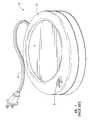
- FIG. 4is a bottom perspective view of the warming apparatus of FIG. 2 showing features that allow for adjustments to cord length and position relative to the warming apparatus housing.
- FIG. 5Ais a perspective view of the warming apparatus of FIG. 2 with the cord positioned so that at least a portion of the cord extends from the right side of the warming apparatus rather than the rear as in FIG. 2 .
- FIG. 5Bis a perspective view of the warming apparatus of FIG. 2 with the cord positioned so that at least a portion of the cord extends from the front of the warming apparatus.
- FIG. 6illustrates an embodiment of an adjustable cord utilizing a rotatable spool with coiled spring to more precisely adjust the cord length as desired.
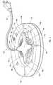
- FIG. 7is a perspective view of a warming apparatus according to the present invention illustrating the manner in which a light source disposed within the hot plate can be used to illuminate a transparent or translucent object resting on the hot plate.
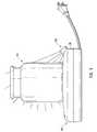
- FIG. 8depicts an embodiment of a warming apparatus according to the present invention in which a decorative sleeve is attached to the warming apparatus.
- FIG. 9depicts an embodiment of a warming apparatus in which the lighting source is located external to the hot plate so as to illuminate a transparent or translucent object from the side.
- the present inventionfeatures a warming apparatus. More particularly the invention features a hot plate apparatus adapted to warm an object, such as a scented candle or other object resting thereon.
- the apparatuscan be configured to include one, or a combination of, features, such as one or more light sources for illuminating the candle and/or the warming device, a cord-adjusting apparatus, and/or attachment means for attaching decorative items to the warming apparatus.
- the following disclosurewill feature four focused areas of discussion as follows: 1) the warming apparatus and its functions; 2) the adjustable cord feature; 3) the means for illuminating or the light source; and 4) the attachment apparatus.
- warming apparatus 100comprises a heating surface (e.g. hot plate) 110 , a housing 120 , a switch 130 , an adjustable cord apparatus 140 , a light source 160 , and attachment means 170 . There is also shown an on/off LED 132 and a cord outlet 146 . Warming apparatus 100 is configured to provide heat to an object or substance resting thereon.
- warming apparatus 100has a generally circular or oval shape, any of a variety of configurations are possible.
- warming apparatus 100can be adapted to have a decorative shape, such as a tear drop or flower.
- the warming apparatus 100can also be adapted to heat objects and substances having different sizes, properties, and configurations.
- the surface area of heating surface 110is adapted to correspond with the bottom surface area of a small candle.
- a larger warming apparatus 100is provided having one or more vents to heat the sides of a taller or more massive candle.
- Heating surface 110is adapted to transfer heat to an object or substance in contact therewith from a heating element (not shown).
- heating element and heating surface 110can warm an aromatic candle contained in a glass container. By providing additional heat to the candle, the aroma of the candle can be released without lighting the candle. Not only does this preserve the life of the candle, but can also reduce the fire hazard that can be caused by having a lit candle in a dwelling.
- the use of heating surface 110is not limited to heating of aromatic candles. Heating surface 110 can also be used to heat other objects or substances, such as coffee mugs, tea cups, etc.
- Housing 120is adapted to provide a full or partial covering to internal circuitry associated with heating surface 110 .
- Housing 120provides an insulating covering to protect a user from inadvertent electrical shock or burn caused by touching the internal wiring or heating element associated with heating surface 110 .
- Housing 120can be comprised of a single unit, or two or more sections adapted to be coupled together.
- Housing 120can also be adapted to provide features in addition to the covering of the internal circuitry.
- housing 120can be adapted with an annular flange surrounding the surface of heating surface 110 . The annular flange would provide a mechanism for keeping an object from sliding off the surface of heating surface 110 .
- Housing 120can also provide decorative features to warming apparatus 100 .
- housing 120can be adapted to receive a decorative faceplate having a custom design.
- Switch 130provides a method of actuating and deactivating warming apparatus 100 .
- a variety of switch mechanismscan be utilized to actuate or deactivate heating element and heating surface 110 .
- switch 130comprises a three-way switch. Switch 130 will be discussed in greater detail with reference to FIG. 7 .
- On/off LED 132operates in connection with switch 130 . On/off LED 132 is utilized to provide a visual indication that heating surface 110 is actuated.
- Adjustable cord apparatus 140is adapted to provide electricity to a heating element associated with heating surface 110 while allowing the user to alter the length of the electrical cord that is extending from the warming apparatus.
- Adjustable cord apparatus 140can include a plurality of outlet slots 146 . Outlet slots 146 allow the user to affix the electrical cord to housing 120 . Outlet slots 146 provide alternative positions at which the cord can extend from the warming apparatus 100 .
- the adjustable cord apparatus 140will be discussed in greater detail with reference to FIGS. 4, 5 a , 5 b , and 6 .
- Light source 160is adapted to provide illumination to an object or substance resting on heating surface 110 or housing 120 .
- light source 160can illuminate a candle resting on heating surface 110 .
- light source 160is adapted to be proximal to heating surface 110 .
- Light source 120can comprise one or more types of known lighting mechanisms.
- light source 120comprises a first light emitting diode (LED) 160 a and a second LED 160 b.
- light source 160can comprise one or more incandescent or halogen bulbs. In the case of a halogen bulb, such may also be used to serve as heating means to heat heating surface 110 .
- Light source 160can be coupled to housing 120 or emanate from below heating surface 110 . In one embodiment, light source 160 provides a focused illumination. In an alternative embodiment light source 160 is configured to wrap around the rim portion of housing 120 . Light source can be adapted to illuminate an object resting on heating surface 110 (i.e. candle), an object resting on housing 120 (i.e. decorative cover,) or the warming apparatus 100 itself.
- illumination of the warming apparatuscan be provided independent of actuation of hot plate 100 . This allows a user to selectively illuminate the warming apparatus 100 , such that warming apparatus 100 can be employed as nightlight or decorative accent.
- Light source 160will be discussed in greater detail with reference to FIGS. 7 and 8.
- Attachment means or apparatus 170is provided to permit additional components or materials to be coupled to the warming apparatus.
- attachment means 170comprises a plurality of slots, 170 a and 170 b , configured to allow a decorative cover to be attached to the warming apparatus.
- the decorative coveris attached to warming apparatus 100 using tabs that are insertable into slots 170 a and 170 b .
- Attachment means 170will be discussed in greater detail with reference to FIG. 8 .
- FIG. 2further illustrates temperature switch 230 and timer 240 .
- Temperature switch 230provides for varying temperature control to heating surface 110 .
- Timer 240allows one to set the time at which heating element or heating surface 110 will be actuated. Timer 240 may be set to allow any length of time for the actuation of heating surface 110 . Once the set amount of time elapses, timer 240 deactivates heating surface 110 and warming apparatus 100 shuts off.
- FIG. 3is a side cut-away view illustrating one embodiment of the warming apparatus of the present invention.
- heating surface 110comprises a hot plate contacting surface 112 , a heating element 114 , and a circuit board 116 .
- Hot plate contacting surface 112comprises a metal, ceramic, or other material capable of conducting heat to an object or substance in contact therewith.
- Hot plate contacting surface 112can be coated with Teflon, or another no-stick coating, to allow for easy cleaning.
- Heating element 114is coupled to the hot plate contacting surface 112 .
- Heating element 114is positioned below hot plate contacting surface 112 such that heating element 114 is enclosed by hot plate contacting surface 112 and housing 120 .
- heating element 114is comprised of a ceramic material due to the advantageous properties of ceramic heaters.
- heating element 114is comprised of an element comprised of metal, wire coil, or other materials and constructions adapted to provide heat to hot plate contacting surface 112 .
- Circuit board 116is adapted to provide logic functions required to actuate and deactivate heating surface 110 and first and second LEDs 160 a and 160 b .
- circuit board 116operates in connection with an adjustable rheostat, allowing a user to adoptively alter the temperature of hot plate contacting surface 112 in correspondence with the properties of the object or material resting thereon.
- the rheostatcan be configured to provide temperatures adapted to the particular temperature requirements of different candles (i.e. based on size of the candle or the type of container/wax.)
- Heating surface 110can also include additional components.
- a plastic coatingis included under hot plate contacting surface 112 .
- the plastic coatingprovides an impermeable seal to protect the internal circuitry of heating surface 110 and/or the light source.
- a voltage adapteris included in the internal circuitry of heating surface 110 to allow the warming apparatus 100 to be used with different power sources of different voltages.
- a timeris included to control the functionality of heating surface 110 and/or the light source.
- FIG. 3illustrates the manner in which a light source can be coupled to heating surface 110 .
- first and second LEDs 160 a,bare positioned such that the tip of first and second LEDs 160 a,b fill apertures in hot plate contacting surface 112 .
- the LED'scan be integrally or separably coupled to hot plate contacting surface 112 .
- FIG. 3also illustrates an adjustable cord apparatus 140 .
- Adjustable cord apparatus 140is adapted such that the user can alter the length of the electrical cord that is extending from the warming apparatus. The adjustable cord apparatus 140 will be discussed in greater detail with reference to FIGS. 4 and 5.
- FIG. 4is a bottom view illustrating one embodiment of the adjustable cord apparatus 140 of the present invention.
- adjustable cord apparatus 140comprises a cord 142 , a cord retention mechanism 144 , and cord outlets 146 a-d .
- housing recess 150 and scuff pads 180 a-dare also shown.
- Adjustable cord apparatus 140provides electricity to heating surface 110 while allowing the user to alter the length of the cord that is extending from warming apparatus 100 .
- Cord 142comprises an electrical cord that is electrically connected to the internal circuitry of heating surface 110 .
- Cord 142provides a mechanism for providing electricity to heating surface 110 .
- cord 142is an electrical cord of a type that is typically used with small electronic appliances. As will be understood by those skilled in the art, any electrical cord can be utilized that is suited to the requirements of warming apparatus 100 .
- electrical cord 142is adapted to have changeable electrical plugs allowing the warming apparatus to be plugged into electrical outlets having different configurations.
- Cord retention mechanism 144is adapted to secure some or all of the cord proximate to housing 120 .
- cord retention mechanismpermits the user to coil cord 142 .
- Cord retention mechanism 144includes a plurality of projections 145 a-d .
- Cord 142is positioned such that a retained cord portion 142 a is wrapped below projections 145 a-d , while an extended cord portion 142 b projects from the warming apparatus 100 .
- Projections 145 a-dhold the retained cord portion 142 a in a tightly coiled configuration while allowing the user to alter the length of extended cord portion 142 b by coiling, or uncoiling cord 142 from the cord retention mechanism 144 .
- Cord outlets 146 a-dare adapted to receive cord 142 .
- cord outlets 146 a-dcomprise a plurality of slots adapted to permit the user to affix the cord to housing 120 , thus providing alternative positions at which the cord can extend from warming apparatus 100 .
- cord outlets 146 a-dpermit the user to vary the length of extended cord portion 142 b.
- a housing recess 150is provided to conceal adjustable cord apparatus 140 .
- housing recess 150permits the retained cord portion 142 a and the cord retention mechanism 144 to be concealed when the warming apparatus 100 is in use.
- unneeded portions of cord 142can be quickly and efficiently secured and concealed to provide a more tidy appearance to the warming apparatus 100 .
- Scuff pads 180 a-dare coupled to housing 120 . Scuff pads 180 a-d prevent scratches in surfaces on which warming apparatus 100 is placed. Scuff pads 180 a-d can be adapted to provide a variety of benefits in addition to scratch prevention. For example, scuff pads can be adapted to provide slip resistance or separation between housing 120 and a counter top surface.
- voltage converter 220allowing warming apparatus 100 to switch or alternate voltage levels, shown in FIG. 4 as either 110 or 220 volts. Voltage converter 220 compensates for varying circuitry and power levels existing within a location.
- FIGS. 5 a and 5 bare perspective views of warming apparatus 100 illustrating the way in which adjustable cord apparatus 140 can be used to vary the configuration and length of the cord extending from warming apparatus 100 .
- FIG. 5 athere is shown a configuration of warming apparatus 100 in which the extended cord portion 142 b has a first length.
- the first length of extended cord portion 142 bis a shorter length.
- the shorter cord lengthis accomplished by securing the majority of cord 142 proximate housing 120 utilizing cord retention mechanism 144 .
- Cord 142is affixed to housing 120 using cord outlet 146 . Due to the position of cord outlet 146 , cord 142 extends from warming apparatus 100 from a side different or opposite switch 130 .
- FIG. 5 bthere is shown a configuration of warming apparatus 100 in which the extended cord portion 142 b has a second length.
- the second length of extended cord portion 142 bis a longer length achieved by securing a minority of cord 142 proximate to housing 120 utilizing cord retention mechanism 144 .
- Cord 142is affixed to housing 120 using cord outlet 146 c . Due to the position of cord outlet 146 c , cord 142 extends from warming apparatus 100 from the side proximate switch 130 .
- cord outlet 146 cDue to the position of cord outlet 146 c , cord 142 extends from warming apparatus 100 from the side proximate switch 130 .
- Cord outlets 146 a-dalso allow the user to alter the configuration of warming apparatus 100 by permitting the user to alternate the position at which cord 142 extends from warming apparatus 100 .
- the usercan secure unneeded lengths of electrical cord in a concealed fashion.
- the ability to secure a portion of cord 142can be useful where the distance between the warming apparatus 100 and the electrical outlet is less than the length of cord 142 .
- the adjustable cord apparatus 140can also be useful for neatly storing cord 142 when the warming apparatus 100 is not in use.
- the adjustable cord apparatus 140comprises a spring or biasing coil mechanism.
- the spring coil mechanismis adapted to provide a method of effortlessly altering the length of cord 142 extending from warming apparatus 100 .
- the spring coilis located internal to housing 120 of warming apparatus 100 . This permits some, or all of, cord 142 to be secured and concealed internally in housing 120 .
- spring coil mechanismrotates with respect to housing 120 to coil and uncoil cord 142 .
- tension in the spring or biasing memberincreases having a tendency to want to re-coil and rotate in an opposing direction than taken to uncoil cord 142 .
- a locking mechanismmay be in place to prevent adjustable cord apparatus 140 from re-coiling until desired. If a shorter length of cord is needed, adjustable cord apparatus 140 , and particularly spring coil mechanism, is actuated so that adjustable cord apparatus 140 is causes to rotate and re-coil or wind cord 142 to a desired length.
- adjustable cord apparatus 140While alternative embodiments of adjustable cord apparatus 140 have been described with reference to FIGS. 4, 5 a , 5 c , and 6 , it will be appreciated that additional embodiments of the adjustable cord apparatus can be utilized within the scope and spirit of the present invention.
- FIG. 7illustrates the manner in which a user can utilize illumination means or a light source 160 to illuminate internally, from within, or the outside of an object resting on heating surface 110 .
- a heating surface 110is shown a heating surface 110 , a switch 130 , a candle 190 , and a power source 200 .
- heating surface 110is adapted to provide heat to an object resting thereon.
- Switch 130provides a mechanism for actuating and deactivating heating surface 110 .
- switch 130comprises a three-way switch having a switch knob 134 .
- Switch knob 134allows a user to control functionality associated with warming apparatus 100 . When switch knob 134 is in a first position 136 a , heating surface 110 is actuated and the light source is illuminated.
- both heating surface 110 and the light sourceare deactivated.
- switch knob 134is in a third position 136 c , heating surface 110 is actuated while the light source is deactivated.
- a light emitting diode (LED) 132may be implemented to show or indicate that warming apparatus 100 is actuated and heating.
- switch 130comprises a three-way switch
- any variety of mechanisms for actuating and deactivating heating surface 110 and/or light sourcecan be utilized.
- one or more simple on/off switchescan be utilized.
- a rheostat providing adjustable temperature functionalitycan be provided.
- the usercan be required to actuate and deactivate the hot plate and/or the light source by simply attaching and detaching cord 142 to and from power source 200 .
- switch knob 134is in first position 136 a . Accordingly, heating surface 110 is actuated and the light source is illuminated. Illumination of the light source causes illumination of the object resting on heating surface 110 . Preferably, the illumination of the object is internal or from within to simulate various lighting effects of a burning candle. In the illustrated embodiment, the object resting on heating surface 110 is candle 190 . Where the light source is integrally coupled to heating surface 110 (see FIG. 2 ), illumination of the light source is most readily apparent where the candle, or liquefied wax, is at least partially transparent. In an alternative embodiment of the present invention, the light source is coupled to either heating surface 110 or housing 120 such that opaque objects and/or substances resting on hot plate 120 are illuminated.
- Illumination of objects resting on warming apparatus 100can be adapted to a variety of functions.
- a candlecan be illuminated to emphasize the color of the candle wax or to replicate a burning candle.
- the light sourcecan be utilized to provide lighting for decorative objects and/or features associated with warming apparatus 100 (see FIG. 8 ).
- Illuminationmay be created to be emanate partially from the object or totally from the object.
- partial illuminationmay be achieved by providing one or more lighting sources targeted or directed towards the object, as shown in FIG. 9 .
- Total illumination, or illumination emanating from within the objectmay be achieved by using lighting sources 160 as illustrated in FIG. 2 .
- FIG. 8shows one embodiment of the warming apparatus 100 of the present invention illustrating the method in which attachment means 170 can be utilized.
- Attachment means 170permits additional and/or peripheral components, materials, objects, devices, covers, faceplates, light sources, etc. (collectively known as peripherals) to be coupled or interchangeably coupled to warming apparatus 100 .
- attachment means 170comprises a plurality of slots 170 a and 170 b configured to allow a peripheral to be attached to warming apparatus 100 .
- Slots 170 a and 170 bare integrally coupled to housing 120 .
- Slots 170 a and 170 bare configured to receive corresponding tabs included on the peripheral. Slots 170 a and 170 b and tabs of the peripheral allow the peripheral to be selectively attached and removed from warming apparatus 100 .
- attachment means 170is not limited to the configuration of the illustrated embodiment. A variety of configurations and mechanisms can be employed in scope and spirit of the present invention.
- attachment means 170may comprise one or more clips configured to allow materials or modules to be attached to the warming apparatus, or attachment means 170 may comprise other various known devices, structures, assemblies, etc. designed to allow one or more peripherals to be removably coupled to warming apparatus 100 .
- warming apparatus 100may comprise snaps, Velcro®, a tongue and groove assembly, a snap-fit extension and receiver assembly, threading, an interference fit assembly, or any other known and obvious means capable of removably coupling a peripheral item to the warming apparatus.
- warming apparatus 100is designed to accept several different types of peripherals through use of attachment means 170 .
- warming apparatus 100is adapted to receive one or more face plates thereon.
- the face platesare preferably interchangeable in order to accommodate the changing of several themes or to be adaptable to different environments, etc. in which warming apparatus 100 may be placed.
- these face platesmay be fixed or rigidly attached.
- the face platesmay comprise any color, shape, wording, graphic, or texture as desirable.
- the several face platesmay comprise themes corresponding to the several holidays existing throughout the year, such as Christmas, Thanksgiving, Halloween, and Valentine's Day, or may comprise various designs, colors, and/or patterns to match the interior design of the particular environment in which warming apparatus 100 is placed.
- the present inventioncontemplates the ability to alter its physical appearance and design through the interchanging of one or more detachable face plates.
- warming apparatus 100is adapted to receive a peripheral in the form of decorative cover 210 .
- Decorative cover 210may include a cover design 212 to enhance the aesthetics of the cover.
- the configuration of decorative cover 210can include a variety of designs and colors.
- the decorative covercan have a uniform opaque, variable transparent, or semitransparent design, or any other conceivable configuration.
- decorative cover 210is comprised primarily of an opaque material.
- Cover design 212may be added to lend aesthetic ornamentation to decorative cover 210 .
- the portion of decorative cover 210 corresponding to cover design 212comprises an aperture or transparent material allowing the light source to provide a backlight to accent or highlight cover design 212 .
- the light source and the peripheralnamely the cover and cover design, can be utilized to achieve a variety of different aesthetic features.
- a decorative coverconfigured to substantially cover a candle resting on the hot plate is affixed to the warming apparatus utilizing the attachment apparatus.
- the light sourceis adapted to provide a flickering illumination, thus lending the impression that the candle is lit.
- warming apparatus 100is adapted to receive a peripheral in the form of one or more crafts and/or modules.
- Example craftsmay include such items as flowers, wreaths, shams, skirts, etc.
- Modulesmay include any device or structure or item that protrudes out from warming apparatus 100 and that is removably attached to warming apparatus 100 using attachment means 170 .
- attachment means 170For example, during Christmas, one may wish to attach a candy holder, a bell, an ornament, etc.; or, one may desire to attach a figurine, etc.; or, one may wish to attach exterior lights.
- the present inventionfurther contemplates the attachment or coupling of a heat condenser to warming apparatus 100 using attachment means 170 .
- the heat condenseris designed to focus heat from heating surface 110 to an object proximate heating surface 110 .
- the heat condensercan be utilized, for example, where a the surface area of the bottom of a candle is much smaller than the surface area of contacting surface 112 .
- the heat condenserfocuses the heat emanating from the larger contacting surface 112 to the candle.
- FIG. 9illustrates one embodiment of warming apparatus 100 in which lighting source 250 is located external to heating surface so as to illuminate a transparent or translucent object from the side.
- lighting source 250may be employed to provide various ambient lighting effects.
Landscapes
- Health & Medical Sciences (AREA)
- Epidemiology (AREA)
- Life Sciences & Earth Sciences (AREA)
- Animal Behavior & Ethology (AREA)
- General Health & Medical Sciences (AREA)
- Public Health (AREA)
- Veterinary Medicine (AREA)
- Arrangement Of Elements, Cooling, Sealing, Or The Like Of Lighting Devices (AREA)
- Non-Portable Lighting Devices Or Systems Thereof (AREA)
Abstract
Description
Claims (64)
Priority Applications (4)
| Application Number | Priority Date | Filing Date | Title |
|---|---|---|---|
| US10/197,013US6627857B1 (en) | 2002-05-09 | 2002-07-18 | Illuminating candle warming apparatus |
| PCT/US2002/023500WO2003096748A1 (en) | 2002-05-09 | 2002-07-19 | Illuminating candle warming apparatus |
| AU2002317570AAU2002317570A1 (en) | 2002-05-09 | 2002-07-19 | Illuminating candle warming apparatus |
| US10/308,342US7067772B2 (en) | 2002-05-09 | 2002-12-03 | Candle warming apparatus |
Applications Claiming Priority (2)
| Application Number | Priority Date | Filing Date | Title |
|---|---|---|---|
| US37909402P | 2002-05-09 | 2002-05-09 | |
| US10/197,013US6627857B1 (en) | 2002-05-09 | 2002-07-18 | Illuminating candle warming apparatus |
Related Child Applications (1)
| Application Number | Title | Priority Date | Filing Date |
|---|---|---|---|
| US10/308,342DivisionUS7067772B2 (en) | 2002-05-09 | 2002-12-03 | Candle warming apparatus |
Publications (1)
| Publication Number | Publication Date |
|---|---|
| US6627857B1true US6627857B1 (en) | 2003-09-30 |
Family
ID=28456801
Family Applications (2)
| Application Number | Title | Priority Date | Filing Date |
|---|---|---|---|
| US10/197,013Expired - LifetimeUS6627857B1 (en) | 2002-05-09 | 2002-07-18 | Illuminating candle warming apparatus |
| US10/308,342Expired - Fee RelatedUS7067772B2 (en) | 2002-05-09 | 2002-12-03 | Candle warming apparatus |
Family Applications After (1)
| Application Number | Title | Priority Date | Filing Date |
|---|---|---|---|
| US10/308,342Expired - Fee RelatedUS7067772B2 (en) | 2002-05-09 | 2002-12-03 | Candle warming apparatus |
Country Status (3)
| Country | Link |
|---|---|
| US (2) | US6627857B1 (en) |
| AU (1) | AU2002317570A1 (en) |
| WO (1) | WO2003096748A1 (en) |
Cited By (74)
| Publication number | Priority date | Publication date | Assignee | Title |
|---|---|---|---|---|
| US20040246711A1 (en)* | 2001-05-18 | 2004-12-09 | Rachel Brenchley | Apparatus and method for flameless burning of candles |
| US20050016985A1 (en)* | 2003-05-01 | 2005-01-27 | Rodney Haas | Electrically-operated temperature-regulated scented wax warmer |
| US20050053368A1 (en)* | 2003-09-04 | 2005-03-10 | Bradley Pesu | Illuminated air freshener |
| US20050150886A1 (en)* | 2004-01-12 | 2005-07-14 | Andrew Niemeyer | Heater for scented candles |
| US20050169846A1 (en)* | 2004-01-31 | 2005-08-04 | Bart Kennington | Enhancement of fragrance release from candles |
| US20050195600A1 (en)* | 2004-03-03 | 2005-09-08 | S.C. Johnson & Son, Inc. | Led light bulb with active ingredient emission |
| US20060018786A1 (en)* | 2004-07-20 | 2006-01-26 | Jc Candle Company, Inc. | Multi-compartment container for use in producing an aroma |
| USD522671S1 (en)* | 2005-02-01 | 2006-06-06 | Crazy Mountain Imports, Inc. | Candle warmer |
| US20060138120A1 (en)* | 2004-12-27 | 2006-06-29 | Taylor Curtis P | Warming device and methods for warming an article |
| US20060138119A1 (en)* | 2004-12-27 | 2006-06-29 | Taylor Curtis P | Warming device and methods for warming an article |
| WO2006071888A3 (en)* | 2004-12-27 | 2006-09-14 | Consumer Innovation Partners L | Warming device and methods for warming an article |
| US20060240371A1 (en)* | 2005-04-25 | 2006-10-26 | Rimports (Usa) Llc | Cover for a candle warmer |
| US20060272199A1 (en)* | 2005-06-02 | 2006-12-07 | Bmc Manufacturing, Llc | Aqueous gel candle for use with a warming device |
| US7188780B2 (en) | 2004-06-30 | 2007-03-13 | S.C. Johnson & Son, Inc. | Volatile material expiration indicating system |
| USD542437S1 (en) | 2005-06-14 | 2007-05-08 | Wesley Snow | Candle warmer |
| US7213770B2 (en) | 2004-06-30 | 2007-05-08 | S. C. Johnson & Son, Inc. | Volatile material dispensing system |
| US20070158326A1 (en)* | 2006-01-06 | 2007-07-12 | Ming-Ren Xiao | Wax burning device |
| US20070180759A1 (en)* | 2006-02-08 | 2007-08-09 | Bart Kennington | Quick and safe release of candle fragrance |
| US7318659B2 (en) | 2004-03-03 | 2008-01-15 | S. C. Johnson & Son, Inc. | Combination white light and colored LED light device with active ingredient emission |
| USD575422S1 (en) | 2007-05-22 | 2008-08-19 | S.C. Johnson & Son, Inc. | Decorative candleholder |
| US7426799B2 (en) | 2004-06-30 | 2008-09-23 | S.C. Johnson & Son, Inc. | Air freshener with frame and refill holder |
| US7441360B2 (en) | 2004-06-30 | 2008-10-28 | S.C. Johnson & Son, Inc. | Air freshener with picture frame |
| US7476002B2 (en) | 2003-07-02 | 2009-01-13 | S.C. Johnson & Son, Inc. | Color changing light devices with active ingredient and sound emission for mood enhancement |
| US7484860B2 (en) | 2003-07-02 | 2009-02-03 | S.C. Johnson & Son, Inc. | Combination white light and colored LED light device with active ingredient emission |
| US7503675B2 (en) | 2004-03-03 | 2009-03-17 | S.C. Johnson & Son, Inc. | Combination light device with insect control ingredient emission |
| US7520635B2 (en) | 2003-07-02 | 2009-04-21 | S.C. Johnson & Son, Inc. | Structures for color changing light devices |
| US7523577B2 (en) | 2006-04-03 | 2009-04-28 | S.C. Johnson & Son, Inc. | Air freshener with holder |
| US20090238685A1 (en)* | 2006-05-08 | 2009-09-24 | Roland Santa Ana | Disguised air displacement device |
| USD602615S1 (en)* | 2008-09-29 | 2009-10-20 | Yi-Chuan Liu | Combined portable nightlight and charger |
| US7604378B2 (en) | 2003-07-02 | 2009-10-20 | S.C. Johnson & Son, Inc. | Color changing outdoor lights with active ingredient and sound emission |
| US7607250B2 (en) | 2004-06-30 | 2009-10-27 | S.C. Johnson & Son, Inc. | Air freshener with picture frame |
| US7637737B2 (en) | 1999-12-21 | 2009-12-29 | S.C. Johnson & Son, Inc. | Candle assembly with light emitting system |
| US20100032494A1 (en)* | 2008-08-05 | 2010-02-11 | Ousley Lisa J | Portable Scent Disperser |
| US7665238B2 (en) | 2006-04-03 | 2010-02-23 | S.C. Johnson & Son, Inc. | Air freshener with holder |
| US7699603B2 (en) | 1999-12-21 | 2010-04-20 | S.C. Johnson & Son, Inc. | Multisensory candle assembly |
| USD620303S1 (en) | 2010-01-28 | 2010-07-27 | Hamilton Beach Brands, Inc. | Percolator |
| USD621014S1 (en) | 2009-04-23 | 2010-08-03 | Heatwave Products, LLC | Towel warming device |
| USD625796S1 (en) | 2009-04-23 | 2010-10-19 | Heatwave Products, LLC | Towel warming device |
| USD626639S1 (en) | 2009-04-23 | 2010-11-02 | Heatwave Products, LLC | Towel warming device |
| US20100290238A1 (en)* | 2009-05-14 | 2010-11-18 | Mary Elle Fashions | Light-emitting apparatus |
| US20110135287A1 (en)* | 2009-12-08 | 2011-06-09 | Wen-Hung Huang | Power supply device with humidifying function |
| US20130020307A1 (en)* | 2011-07-22 | 2013-01-24 | Scentsy, Inc. | Warming device, dish for a warming device and related methods |
| US8364028B1 (en)* | 2008-04-23 | 2013-01-29 | Gold Canyon International, LLC | Plastic scent pod and method for heating a scent pod |
| US8481895B2 (en) | 2004-12-27 | 2013-07-09 | HeatWave | Portable warming device and method for warming an article |
| US8716632B1 (en) | 2008-04-23 | 2014-05-06 | Gold Canyon International, LLC | Ceramic scent bowl and method for heating a scent bowl |
| US20140133132A1 (en)* | 2012-10-24 | 2014-05-15 | Ming Jen Hsiao | Aroma-diffusing heating device |
| US8772675B2 (en) | 2011-06-15 | 2014-07-08 | Scentsy, Inc. | Electrical lighting and heating modules, assemblies and scent warmers comprising such modules, and related methods |
| US8878102B2 (en) | 2011-06-15 | 2014-11-04 | Scentsy, Inc. | Base structures, scent warmers including such base structures, and related methods |
| US20150327722A1 (en)* | 2014-01-25 | 2015-11-19 | Douglas R. Nielson | Candle Warming Image Display Lamp |
| US9211355B2 (en) | 2010-07-27 | 2015-12-15 | Scentsy, Inc. | Scent warmers having non-incandescent heating and light-emitting devices and related methods |
| US9332595B2 (en) | 2012-04-11 | 2016-05-03 | Jeanne M. CALIGIURI | Microwaveable heat retentive container |
| US9500358B2 (en)* | 2012-10-24 | 2016-11-22 | Ming Jen Hsiao | Aroma diffusing heating device using an aroma capsule |
| US20170067608A1 (en)* | 2015-09-03 | 2017-03-09 | Luminara Worldwide, Llc | Electric Lighting Device With Scent Cartridge |
| US9717814B2 (en) | 2010-10-01 | 2017-08-01 | S. C. Johnson & Son, Inc. | Dispensing device |
| US20170238364A1 (en)* | 2014-08-15 | 2017-08-17 | S.C. Johnson & Son, Inc. | Wax warmers |
| US20180070698A1 (en)* | 2016-09-14 | 2018-03-15 | April Bartlett | Depilatory wax melting apparatus |
| USD817525S1 (en)* | 2015-02-27 | 2018-05-08 | Anchor Hocking, Llc | Wax candle vessel |
| CN108055717A (en)* | 2017-12-29 | 2018-05-18 | 安徽省宁国市天成电机有限公司 | A kind of adjustable suspension type, which is heated up water, uses heating tube |
| US10225885B2 (en) | 2014-04-17 | 2019-03-05 | S. C. Johnson & Son, Inc. | Electrical barrier for wax warmer |
| USD846764S1 (en)* | 2015-03-18 | 2019-04-23 | Rimports, LLC—A Sterno Group Company | Candle warmer |
| US10616954B2 (en)* | 2014-04-17 | 2020-04-07 | S. C. Johnson & Son, Inc. | Electrical barrier for wax warmer |
| US11207437B2 (en) | 2016-02-15 | 2021-12-28 | S. C. Johnson & Son, Inc. | Sealed heater engine for a wax warmer |
| KR102387715B1 (en)* | 2020-10-23 | 2022-04-18 | 이가영 | Aroma diffuser |
| USD995884S1 (en)* | 2021-11-05 | 2023-08-15 | Essence Technology Holdings (HK) Limited | Automatic wake-up light |
| USD995826S1 (en)* | 2023-02-15 | 2023-08-15 | Fan CHEN | Candle warmer lamp |
| USD1002072S1 (en)* | 2023-06-26 | 2023-10-17 | Weida Luo | Wax melting lamp |
| USD1002082S1 (en)* | 2023-05-25 | 2023-10-17 | Lin Lin | Candle warmer lamp |
| USD1024385S1 (en)* | 2022-03-02 | 2024-04-23 | Collin D. Bernsen | Shelf with light illumination device |
| USD1035105S1 (en)* | 2023-12-19 | 2024-07-09 | Shuai Han | Candle warmer lamp |
| USD1035973S1 (en)* | 2023-12-14 | 2024-07-16 | Wenqiang Duan | Candle warmer lamp |
| USD1041730S1 (en)* | 2024-01-19 | 2024-09-10 | Kai Chen | Candle warmer lamp |
| USD1047258S1 (en)* | 2024-01-20 | 2024-10-15 | Ya Liang | Candle warmer lamp |
| USD1047259S1 (en)* | 2024-01-20 | 2024-10-15 | Ya Liang | Candle warmer lamp |
| USD1079068S1 (en)* | 2021-03-30 | 2025-06-10 | Lindsay Raquel Pasteris | Reusable candle vessel |
Families Citing this family (26)
| Publication number | Priority date | Publication date | Assignee | Title |
|---|---|---|---|---|
| US20070020573A1 (en)* | 1999-12-21 | 2007-01-25 | Furner Paul E | Candle assembly with light emitting system |
| US7591646B2 (en) | 1999-12-21 | 2009-09-22 | S. C. Johnson & Son, Inc. | Heat exchange method for melting plate candle |
| US7247017B2 (en) | 1999-12-21 | 2007-07-24 | S.C. Johnson & Son, Inc. | Melting plate candles |
| WO2005074999A1 (en) | 2004-02-03 | 2005-08-18 | S.C. Johnson & Son, Inc. | Device providing coordinated emission of light and volatile active |
| US7824627B2 (en) | 2004-02-03 | 2010-11-02 | S.C. Johnson & Son, Inc. | Active material and light emitting device |
| WO2006109218A1 (en)* | 2005-04-14 | 2006-10-19 | Koninklijke Philips Electronics N.V. | Discharge lamp and assembly of a fitting and such a discharge lamp |
| US20070148038A1 (en)* | 2005-04-25 | 2007-06-28 | Sundhar Shaam P | Plug-In Oxygenator |
| US7905224B2 (en)* | 2007-02-15 | 2011-03-15 | Charles Flather | Beverage warmer apparatus |
| US20090289128A1 (en)* | 2008-05-21 | 2009-11-26 | Ben Warren Borchert | Enhancement of fragrance release from top of candles continuity |
| USD599921S1 (en)* | 2008-10-06 | 2009-09-08 | Fish Factory Lighting, Inc. | Surface mountable underwater light |
| WO2011005958A1 (en)* | 2009-07-08 | 2011-01-13 | Heat Seal Llc | Packaging machine |
| US8693852B2 (en) | 2010-05-19 | 2014-04-08 | Partylite Worldwide, Inc. | Warmers for scented oils |
| USD637275S1 (en) | 2010-05-19 | 2011-05-03 | Partylite Worldwide, Inc. | Scented oil warmer |
| USD762294S1 (en) | 2013-12-06 | 2016-07-26 | Burton Hanna | Wax melt |
| US9566362B1 (en) | 2013-12-06 | 2017-02-14 | Burton Hanna | Poured and/or compressed multiple wax object |
| USD748499S1 (en) | 2013-12-06 | 2016-02-02 | Burton Hanna | Package for wax melts |
| US10039851B2 (en)* | 2014-01-28 | 2018-08-07 | S. C. Johnson & Son, Inc. | Wax melt system |
| US9485811B1 (en)* | 2014-03-20 | 2016-11-01 | E. Dean Sansom | Spray bottle warming system |
| KR101735815B1 (en)* | 2015-06-08 | 2017-05-29 | (주) 레판토 | candle warmer with touch type switch |
| US20190307912A1 (en) | 2015-10-20 | 2019-10-10 | Takasago International Corporation | Fragrance delivery device, system, and method |
| US20200069832A1 (en) | 2017-05-08 | 2020-03-05 | Takasago International Corporation | Fragrance releasing device |
| US11000617B1 (en) | 2019-01-10 | 2021-05-11 | Burton Hanna | Safety media for wax melts |
| USD1022571S1 (en)* | 2021-05-03 | 2024-04-16 | Zhan Amalyan | Cup warmer for to-go paper cups |
| US20230341122A1 (en)* | 2022-04-21 | 2023-10-26 | Lee Schaak | Lighting assembly having an integrated coffee/tea heater |
| USD1063497S1 (en)* | 2024-06-18 | 2025-02-25 | Taizhou Fenglu Technology Co., Ltd. | Smoker device |
| USD1071646S1 (en)* | 2024-08-06 | 2025-04-22 | Yuanyuan Wu | Cup warmer |
Citations (16)
| Publication number | Priority date | Publication date | Assignee | Title |
|---|---|---|---|---|
| US2469656A (en) | 1946-04-19 | 1949-05-10 | Peter H Lienert | Vaporizer |
| US3748464A (en) | 1972-02-08 | 1973-07-24 | F Andeweg | Wax shade |
| US3780260A (en)* | 1972-08-04 | 1973-12-18 | E Elsner | Combination night light and liquid vaporizer |
| US3813501A (en)* | 1972-04-06 | 1974-05-28 | Vacuum Cleaner Corp | Electrical cord-reel apparatus |
| US3876861A (en)* | 1974-10-03 | 1975-04-08 | John W Wightman | Heating unit |
| US4330702A (en)* | 1980-10-20 | 1982-05-18 | General Electric Company | Electronic control system for coffeemaker |
| US4399351A (en)* | 1980-12-05 | 1983-08-16 | William Koff | Electric heat exchange cooking apparatus |
| US5032360A (en) | 1987-06-15 | 1991-07-16 | Reagan Houston | Odor remover |
| US5395233A (en) | 1994-01-18 | 1995-03-07 | Scentex, Inc. | Potpourri decorative candle and method of making same |
| US5434386A (en)* | 1993-09-01 | 1995-07-18 | Holmes Products Corp. | Electric circuit having a heater element and a night light |
| US5647052A (en)* | 1995-04-28 | 1997-07-08 | Reckitt & Colman Inc. | Volatile substance dispenser and method of dispensing a volatile substance with dissipation indication |
| US5651942A (en) | 1996-01-11 | 1997-07-29 | Christensen; Arthur E. | Aromatic fragrance generator |
| US5744106A (en) | 1996-10-15 | 1998-04-28 | Eagle; Richard E. | Heated scent dispenser |
| US6106786A (en) | 1998-01-14 | 2000-08-22 | Futaba Denshi Kogyo K.K. | Aroma apparatus |
| US6196706B1 (en) | 1994-01-14 | 2001-03-06 | Creighton Cutts | Glowing electric light assembly |
| US6354710B1 (en) | 2000-09-06 | 2002-03-12 | George J. Nacouzi | Aromatic system and method of use |
Family Cites Families (8)
| Publication number | Priority date | Publication date | Assignee | Title |
|---|---|---|---|---|
| US2348966A (en)* | 1942-02-12 | 1944-05-16 | Air Way Electric Appl Corp | Electric appliance |
| US3948445A (en)* | 1973-06-26 | 1976-04-06 | Andeweg Frits J | Material vapor generator with heat accelerated vapor release |
| US3990848A (en)* | 1975-04-10 | 1976-11-09 | The Risdon Manufacturing Company | System for inducing air flow past a gel type product |
| US4968456A (en)* | 1989-06-02 | 1990-11-06 | Turbo Blast Air Freshener Co., Inc. | Electrical air freshener for automobiles |
| US5498397A (en)* | 1995-05-09 | 1996-03-12 | Horng; Chin-Fu | Air freshener |
| US5684759A (en)* | 1996-08-29 | 1997-11-04 | Ever Splendor Enterprises Co. Ltd. | Electronic timer for a coffee maker |
| US6310329B1 (en)* | 2000-09-08 | 2001-10-30 | Tina H. Carter | Heatable container assembly |
| US6249645B1 (en)* | 2000-09-20 | 2001-06-19 | Tamu Smith | Potpourri kettle that is adapted for use in a vehicle |
- 2002
- 2002-07-18USUS10/197,013patent/US6627857B1/ennot_activeExpired - Lifetime
- 2002-07-19AUAU2002317570Apatent/AU2002317570A1/ennot_activeAbandoned
- 2002-07-19WOPCT/US2002/023500patent/WO2003096748A1/ennot_activeApplication Discontinuation
- 2002-12-03USUS10/308,342patent/US7067772B2/ennot_activeExpired - Fee Related
Patent Citations (16)
| Publication number | Priority date | Publication date | Assignee | Title |
|---|---|---|---|---|
| US2469656A (en) | 1946-04-19 | 1949-05-10 | Peter H Lienert | Vaporizer |
| US3748464A (en) | 1972-02-08 | 1973-07-24 | F Andeweg | Wax shade |
| US3813501A (en)* | 1972-04-06 | 1974-05-28 | Vacuum Cleaner Corp | Electrical cord-reel apparatus |
| US3780260A (en)* | 1972-08-04 | 1973-12-18 | E Elsner | Combination night light and liquid vaporizer |
| US3876861A (en)* | 1974-10-03 | 1975-04-08 | John W Wightman | Heating unit |
| US4330702A (en)* | 1980-10-20 | 1982-05-18 | General Electric Company | Electronic control system for coffeemaker |
| US4399351A (en)* | 1980-12-05 | 1983-08-16 | William Koff | Electric heat exchange cooking apparatus |
| US5032360A (en) | 1987-06-15 | 1991-07-16 | Reagan Houston | Odor remover |
| US5434386A (en)* | 1993-09-01 | 1995-07-18 | Holmes Products Corp. | Electric circuit having a heater element and a night light |
| US6196706B1 (en) | 1994-01-14 | 2001-03-06 | Creighton Cutts | Glowing electric light assembly |
| US5395233A (en) | 1994-01-18 | 1995-03-07 | Scentex, Inc. | Potpourri decorative candle and method of making same |
| US5647052A (en)* | 1995-04-28 | 1997-07-08 | Reckitt & Colman Inc. | Volatile substance dispenser and method of dispensing a volatile substance with dissipation indication |
| US5651942A (en) | 1996-01-11 | 1997-07-29 | Christensen; Arthur E. | Aromatic fragrance generator |
| US5744106A (en) | 1996-10-15 | 1998-04-28 | Eagle; Richard E. | Heated scent dispenser |
| US6106786A (en) | 1998-01-14 | 2000-08-22 | Futaba Denshi Kogyo K.K. | Aroma apparatus |
| US6354710B1 (en) | 2000-09-06 | 2002-03-12 | George J. Nacouzi | Aromatic system and method of use |
Cited By (94)
| Publication number | Priority date | Publication date | Assignee | Title |
|---|---|---|---|---|
| US7699603B2 (en) | 1999-12-21 | 2010-04-20 | S.C. Johnson & Son, Inc. | Multisensory candle assembly |
| US7637737B2 (en) | 1999-12-21 | 2009-12-29 | S.C. Johnson & Son, Inc. | Candle assembly with light emitting system |
| US20040246711A1 (en)* | 2001-05-18 | 2004-12-09 | Rachel Brenchley | Apparatus and method for flameless burning of candles |
| US20050016985A1 (en)* | 2003-05-01 | 2005-01-27 | Rodney Haas | Electrically-operated temperature-regulated scented wax warmer |
| US7618151B2 (en) | 2003-07-02 | 2009-11-17 | S.C. Johnson & Son, Inc. | Combination compact flourescent light with active ingredient emission |
| US7604378B2 (en) | 2003-07-02 | 2009-10-20 | S.C. Johnson & Son, Inc. | Color changing outdoor lights with active ingredient and sound emission |
| US7520635B2 (en) | 2003-07-02 | 2009-04-21 | S.C. Johnson & Son, Inc. | Structures for color changing light devices |
| US7484860B2 (en) | 2003-07-02 | 2009-02-03 | S.C. Johnson & Son, Inc. | Combination white light and colored LED light device with active ingredient emission |
| US7476002B2 (en) | 2003-07-02 | 2009-01-13 | S.C. Johnson & Son, Inc. | Color changing light devices with active ingredient and sound emission for mood enhancement |
| US7277626B2 (en)* | 2003-09-04 | 2007-10-02 | Bath & Body Works Brand Management, Inc. | Illuminated air freshener |
| US20050053368A1 (en)* | 2003-09-04 | 2005-03-10 | Bradley Pesu | Illuminated air freshener |
| US7133605B2 (en) | 2004-01-12 | 2006-11-07 | Crazy Mountain Imports, Inc. | Heater for scented candles |
| US20050150886A1 (en)* | 2004-01-12 | 2005-07-14 | Andrew Niemeyer | Heater for scented candles |
| US20060269885A1 (en)* | 2004-01-31 | 2006-11-30 | Candle Warmers Etc. Inc. | Enhancement of fragrance release from candles |
| US20050169846A1 (en)* | 2004-01-31 | 2005-08-04 | Bart Kennington | Enhancement of fragrance release from candles |
| US20050195600A1 (en)* | 2004-03-03 | 2005-09-08 | S.C. Johnson & Son, Inc. | Led light bulb with active ingredient emission |
| US7318659B2 (en) | 2004-03-03 | 2008-01-15 | S. C. Johnson & Son, Inc. | Combination white light and colored LED light device with active ingredient emission |
| US7503675B2 (en) | 2004-03-03 | 2009-03-17 | S.C. Johnson & Son, Inc. | Combination light device with insect control ingredient emission |
| US7246919B2 (en) | 2004-03-03 | 2007-07-24 | S.C. Johnson & Son, Inc. | LED light bulb with active ingredient emission |
| US7188780B2 (en) | 2004-06-30 | 2007-03-13 | S.C. Johnson & Son, Inc. | Volatile material expiration indicating system |
| US7607250B2 (en) | 2004-06-30 | 2009-10-27 | S.C. Johnson & Son, Inc. | Air freshener with picture frame |
| US7426799B2 (en) | 2004-06-30 | 2008-09-23 | S.C. Johnson & Son, Inc. | Air freshener with frame and refill holder |
| US7441360B2 (en) | 2004-06-30 | 2008-10-28 | S.C. Johnson & Son, Inc. | Air freshener with picture frame |
| US7213770B2 (en) | 2004-06-30 | 2007-05-08 | S. C. Johnson & Son, Inc. | Volatile material dispensing system |
| US20060018786A1 (en)* | 2004-07-20 | 2006-01-26 | Jc Candle Company, Inc. | Multi-compartment container for use in producing an aroma |
| US8481895B2 (en) | 2004-12-27 | 2013-07-09 | HeatWave | Portable warming device and method for warming an article |
| US20060138120A1 (en)* | 2004-12-27 | 2006-06-29 | Taylor Curtis P | Warming device and methods for warming an article |
| WO2006071888A3 (en)* | 2004-12-27 | 2006-09-14 | Consumer Innovation Partners L | Warming device and methods for warming an article |
| US20060138119A1 (en)* | 2004-12-27 | 2006-06-29 | Taylor Curtis P | Warming device and methods for warming an article |
| USD522671S1 (en)* | 2005-02-01 | 2006-06-06 | Crazy Mountain Imports, Inc. | Candle warmer |
| US20060240371A1 (en)* | 2005-04-25 | 2006-10-26 | Rimports (Usa) Llc | Cover for a candle warmer |
| US7329839B2 (en) | 2005-04-25 | 2008-02-12 | Palmer Jeffery W | Cover for a candle warmer |
| US20060272199A1 (en)* | 2005-06-02 | 2006-12-07 | Bmc Manufacturing, Llc | Aqueous gel candle for use with a warming device |
| USD542437S1 (en) | 2005-06-14 | 2007-05-08 | Wesley Snow | Candle warmer |
| US20070158326A1 (en)* | 2006-01-06 | 2007-07-12 | Ming-Ren Xiao | Wax burning device |
| US20070180759A1 (en)* | 2006-02-08 | 2007-08-09 | Bart Kennington | Quick and safe release of candle fragrance |
| US7665238B2 (en) | 2006-04-03 | 2010-02-23 | S.C. Johnson & Son, Inc. | Air freshener with holder |
| US7523577B2 (en) | 2006-04-03 | 2009-04-28 | S.C. Johnson & Son, Inc. | Air freshener with holder |
| US20090238685A1 (en)* | 2006-05-08 | 2009-09-24 | Roland Santa Ana | Disguised air displacement device |
| USD575422S1 (en) | 2007-05-22 | 2008-08-19 | S.C. Johnson & Son, Inc. | Decorative candleholder |
| US8364028B1 (en)* | 2008-04-23 | 2013-01-29 | Gold Canyon International, LLC | Plastic scent pod and method for heating a scent pod |
| US8716632B1 (en) | 2008-04-23 | 2014-05-06 | Gold Canyon International, LLC | Ceramic scent bowl and method for heating a scent bowl |
| US20100032494A1 (en)* | 2008-08-05 | 2010-02-11 | Ousley Lisa J | Portable Scent Disperser |
| US7931213B2 (en) | 2008-08-05 | 2011-04-26 | Ousley Lisa J | Portable scent disperser |
| USD602615S1 (en)* | 2008-09-29 | 2009-10-20 | Yi-Chuan Liu | Combined portable nightlight and charger |
| USD621014S1 (en) | 2009-04-23 | 2010-08-03 | Heatwave Products, LLC | Towel warming device |
| USD625796S1 (en) | 2009-04-23 | 2010-10-19 | Heatwave Products, LLC | Towel warming device |
| USD626639S1 (en) | 2009-04-23 | 2010-11-02 | Heatwave Products, LLC | Towel warming device |
| US20100290238A1 (en)* | 2009-05-14 | 2010-11-18 | Mary Elle Fashions | Light-emitting apparatus |
| CN102460004A (en)* | 2009-05-14 | 2012-05-16 | 玛丽艾拉时尚公司 | Light emitting device |
| US8215789B2 (en)* | 2009-05-14 | 2012-07-10 | Mary Elle Fashions | Light-emitting apparatus |
| US20110135287A1 (en)* | 2009-12-08 | 2011-06-09 | Wen-Hung Huang | Power supply device with humidifying function |
| USD620303S1 (en) | 2010-01-28 | 2010-07-27 | Hamilton Beach Brands, Inc. | Percolator |
| US9211355B2 (en) | 2010-07-27 | 2015-12-15 | Scentsy, Inc. | Scent warmers having non-incandescent heating and light-emitting devices and related methods |
| US9717814B2 (en) | 2010-10-01 | 2017-08-01 | S. C. Johnson & Son, Inc. | Dispensing device |
| US8772675B2 (en) | 2011-06-15 | 2014-07-08 | Scentsy, Inc. | Electrical lighting and heating modules, assemblies and scent warmers comprising such modules, and related methods |
| US8878102B2 (en) | 2011-06-15 | 2014-11-04 | Scentsy, Inc. | Base structures, scent warmers including such base structures, and related methods |
| US9125956B2 (en) | 2011-06-15 | 2015-09-08 | Scentsy, Inc. | Electrical lighting and heating modules, assemblies and scent warmers comprising such modules, and related methods |
| US9775925B2 (en) | 2011-06-15 | 2017-10-03 | Scentsy, Inc. | Scent warmers and related methods |
| US9775926B2 (en) | 2011-06-15 | 2017-10-03 | Scentsy, Inc. | Scent warmers including lighting and heating modules and related methods |
| US9345800B2 (en) | 2011-06-15 | 2016-05-24 | Scentsy, Inc. | Base structures, scent warmers including such base structures, and related methods |
| US20130020307A1 (en)* | 2011-07-22 | 2013-01-24 | Scentsy, Inc. | Warming device, dish for a warming device and related methods |
| US9332595B2 (en) | 2012-04-11 | 2016-05-03 | Jeanne M. CALIGIURI | Microwaveable heat retentive container |
| US9410695B2 (en)* | 2012-10-24 | 2016-08-09 | Ming Jen Hsiao | Aroma-diffusing heating device |
| US9500358B2 (en)* | 2012-10-24 | 2016-11-22 | Ming Jen Hsiao | Aroma diffusing heating device using an aroma capsule |
| US20140133132A1 (en)* | 2012-10-24 | 2014-05-15 | Ming Jen Hsiao | Aroma-diffusing heating device |
| US20150328353A1 (en)* | 2014-01-25 | 2015-11-19 | Michael R. Schramm | Candle Warming Image Display Lamp |
| US20150327722A1 (en)* | 2014-01-25 | 2015-11-19 | Douglas R. Nielson | Candle Warming Image Display Lamp |
| US10322200B2 (en)* | 2014-01-25 | 2019-06-18 | Michael R. Schramm | Candle warming image display lamp |
| US10616954B2 (en)* | 2014-04-17 | 2020-04-07 | S. C. Johnson & Son, Inc. | Electrical barrier for wax warmer |
| US10225885B2 (en) | 2014-04-17 | 2019-03-05 | S. C. Johnson & Son, Inc. | Electrical barrier for wax warmer |
| US20170238364A1 (en)* | 2014-08-15 | 2017-08-17 | S.C. Johnson & Son, Inc. | Wax warmers |
| US10524311B2 (en)* | 2014-08-15 | 2019-12-31 | S.C. Johnson & Son, Inc. | Wax warmers |
| USD817525S1 (en)* | 2015-02-27 | 2018-05-08 | Anchor Hocking, Llc | Wax candle vessel |
| USD846764S1 (en)* | 2015-03-18 | 2019-04-23 | Rimports, LLC—A Sterno Group Company | Candle warmer |
| US10161584B2 (en)* | 2015-09-03 | 2018-12-25 | Luminara Worldwide, Llc | Electric lighting device with scent cartridge |
| US20170067608A1 (en)* | 2015-09-03 | 2017-03-09 | Luminara Worldwide, Llc | Electric Lighting Device With Scent Cartridge |
| US11207437B2 (en) | 2016-02-15 | 2021-12-28 | S. C. Johnson & Son, Inc. | Sealed heater engine for a wax warmer |
| US10238200B2 (en)* | 2016-09-14 | 2019-03-26 | April Bartlett | Depilatory wax melting apparatus |
| US20180070698A1 (en)* | 2016-09-14 | 2018-03-15 | April Bartlett | Depilatory wax melting apparatus |
| CN108055717A (en)* | 2017-12-29 | 2018-05-18 | 安徽省宁国市天成电机有限公司 | A kind of adjustable suspension type, which is heated up water, uses heating tube |
| CN108055717B (en)* | 2017-12-29 | 2024-02-27 | 安徽省宁国市天成电机有限公司 | Adjustable hanging type heating pipe for water heating |
| KR102387715B1 (en)* | 2020-10-23 | 2022-04-18 | 이가영 | Aroma diffuser |
| USD1079068S1 (en)* | 2021-03-30 | 2025-06-10 | Lindsay Raquel Pasteris | Reusable candle vessel |
| USD995884S1 (en)* | 2021-11-05 | 2023-08-15 | Essence Technology Holdings (HK) Limited | Automatic wake-up light |
| USD1024385S1 (en)* | 2022-03-02 | 2024-04-23 | Collin D. Bernsen | Shelf with light illumination device |
| USD995826S1 (en)* | 2023-02-15 | 2023-08-15 | Fan CHEN | Candle warmer lamp |
| USD1002082S1 (en)* | 2023-05-25 | 2023-10-17 | Lin Lin | Candle warmer lamp |
| USD1002072S1 (en)* | 2023-06-26 | 2023-10-17 | Weida Luo | Wax melting lamp |
| USD1035973S1 (en)* | 2023-12-14 | 2024-07-16 | Wenqiang Duan | Candle warmer lamp |
| USD1035105S1 (en)* | 2023-12-19 | 2024-07-09 | Shuai Han | Candle warmer lamp |
| USD1041730S1 (en)* | 2024-01-19 | 2024-09-10 | Kai Chen | Candle warmer lamp |
| USD1047258S1 (en)* | 2024-01-20 | 2024-10-15 | Ya Liang | Candle warmer lamp |
| USD1047259S1 (en)* | 2024-01-20 | 2024-10-15 | Ya Liang | Candle warmer lamp |
Also Published As
| Publication number | Publication date |
|---|---|
| US7067772B2 (en) | 2006-06-27 |
| US20030209533A1 (en) | 2003-11-13 |
| AU2002317570A1 (en) | 2003-11-11 |
| WO2003096748A1 (en) | 2003-11-20 |
Similar Documents
| Publication | Publication Date | Title |
|---|---|---|
| US6627857B1 (en) | Illuminating candle warming apparatus | |
| US8137630B2 (en) | Light-emitting smell-altering aroma dispenser | |
| US20080129226A1 (en) | Simulated Open Flame Illumination | |
| US9211355B2 (en) | Scent warmers having non-incandescent heating and light-emitting devices and related methods | |
| AU2006331898B2 (en) | Candle assembly with light emitting system | |
| AU2005219978B2 (en) | LED light bulb with active ingredient emission | |
| US7476002B2 (en) | Color changing light devices with active ingredient and sound emission for mood enhancement | |
| EP2074869B1 (en) | Structures for color-changing light devices | |
| US20080130266A1 (en) | Fragrancer | |
| US5455750A (en) | Artificial Christmas tree with scent, sound and visual elements incorporated therein | |
| US7132084B1 (en) | Candle warmer | |
| US20100270943A1 (en) | College and pro sports fragrance oil warmers | |
| US20060018786A1 (en) | Multi-compartment container for use in producing an aroma | |
| US20070020572A1 (en) | Candle and luminary light show | |
| US20040246711A1 (en) | Apparatus and method for flameless burning of candles | |
| US6461014B1 (en) | Ornamental device with thermal cycle of flame | |
| US20080116197A1 (en) | Heater for Aromatic Candles | |
| AU2006331866A1 (en) | Candle and luminary light show | |
| CN216897236U (en) | Rotatable wax melting fragrance lamp | |
| GB2469505A (en) | Light-emitting aroma dispenser | |
| EP2412389A1 (en) | Scent warmers having non-incandescent heating and light-emitting devices and related methods | |
| AU2009100362A4 (en) | Light-emitting smell-altering aroma dispenser | |
| CN212226978U (en) | Fragrance lamp | |
| AU2011286420B2 (en) | Scent warmers having non-incandescent heating and light-emitting devices and related methods |
Legal Events
| Date | Code | Title | Description |
|---|---|---|---|
| AS | Assignment | Owner name:PARK CITIES CAPITAL, L.L.C., UTAH Free format text:ASSIGNMENT OF ASSIGNORS INTEREST;ASSIGNORS:TANNER, BRENT ROBERT;JACOBSEN, GREG GERARD;REEL/FRAME:013213/0592 Effective date:20021028 | |
| AS | Assignment | Owner name:CANDLE WARMERS ETC., INC., UTAH Free format text:ASSIGNMENT OF ASSIGNORS INTEREST;ASSIGNOR:PARK CITIES CAPITAL, LLC, A NEVADA LIMITED LIABILITY COMPANY;REEL/FRAME:014261/0744 Effective date:20040114 | |
| FPAY | Fee payment | Year of fee payment:4 | |
| AS | Assignment | Owner name:CANDLE WARMERS, ETC., UTAH Free format text:ASSIGNMENT OF ASSIGNORS INTEREST;ASSIGNOR:PARK CITIES CAPITAL, LLC;REEL/FRAME:022482/0785 Effective date:20090313 | |
| AS | Assignment | Owner name:KENNINGTON, BART, UTAH Free format text:ASSIGNMENT OF ASSIGNORS INTEREST;ASSIGNOR:CANDLE WARMERS ETC., INC.;REEL/FRAME:022645/0054 Effective date:20090403 | |
| REMI | Maintenance fee reminder mailed | ||
| LAPS | Lapse for failure to pay maintenance fees | ||
| REIN | Reinstatement after maintenance fee payment confirmed | ||
| FP | Lapsed due to failure to pay maintenance fee | Effective date:20110930 | |
| FEPP | Fee payment procedure | Free format text:PETITION RELATED TO MAINTENANCE FEES GRANTED (ORIGINAL EVENT CODE: PMFG); ENTITY STATUS OF PATENT OWNER: SMALL ENTITY | |
| FEPP | Fee payment procedure | Free format text:PETITION RELATED TO MAINTENANCE FEES FILED (ORIGINAL EVENT CODE: PMFP); ENTITY STATUS OF PATENT OWNER: SMALL ENTITY | |
| FPAY | Fee payment | Year of fee payment:8 | |
| PRDP | Patent reinstated due to the acceptance of a late maintenance fee | Effective date:20131007 | |
| STCF | Information on status: patent grant | Free format text:PATENTED CASE | |
| FPAY | Fee payment | Year of fee payment:12 |