US6626909B2 - Apparatus and method for spine fixation - Google Patents
Apparatus and method for spine fixationDownload PDFInfo
- Publication number
- US6626909B2 US6626909B2US10/185,477US18547702AUS6626909B2US 6626909 B2US6626909 B2US 6626909B2US 18547702 AUS18547702 AUS 18547702AUS 6626909 B2US6626909 B2US 6626909B2
- Authority
- US
- United States
- Prior art keywords
- vertebra
- elongated
- screws
- location
- spine fixation
- Prior art date
- Legal status (The legal status is an assumption and is not a legal conclusion. Google has not performed a legal analysis and makes no representation as to the accuracy of the status listed.)
- Expired - Lifetime
Links
Images


Classifications
- A—HUMAN NECESSITIES
- A61—MEDICAL OR VETERINARY SCIENCE; HYGIENE
- A61B—DIAGNOSIS; SURGERY; IDENTIFICATION
- A61B17/00—Surgical instruments, devices or methods
- A61B17/56—Surgical instruments or methods for treatment of bones or joints; Devices specially adapted therefor
- A61B17/58—Surgical instruments or methods for treatment of bones or joints; Devices specially adapted therefor for osteosynthesis, e.g. bone plates, screws or setting implements
- A61B17/68—Internal fixation devices, including fasteners and spinal fixators, even if a part thereof projects from the skin
- A61B17/70—Spinal positioners or stabilisers, e.g. stabilisers comprising fluid filler in an implant
- A61B17/7059—Cortical plates
- A—HUMAN NECESSITIES
- A61—MEDICAL OR VETERINARY SCIENCE; HYGIENE
- A61B—DIAGNOSIS; SURGERY; IDENTIFICATION
- A61B17/00—Surgical instruments, devices or methods
- A61B17/56—Surgical instruments or methods for treatment of bones or joints; Devices specially adapted therefor
- A61B17/58—Surgical instruments or methods for treatment of bones or joints; Devices specially adapted therefor for osteosynthesis, e.g. bone plates, screws or setting implements
- A61B17/68—Internal fixation devices, including fasteners and spinal fixators, even if a part thereof projects from the skin
- A61B17/70—Spinal positioners or stabilisers, e.g. stabilisers comprising fluid filler in an implant
- A61B17/7062—Devices acting on, attached to, or simulating the effect of, vertebral processes, vertebral facets or ribs ; Tools for such devices
- A—HUMAN NECESSITIES
- A61—MEDICAL OR VETERINARY SCIENCE; HYGIENE
- A61B—DIAGNOSIS; SURGERY; IDENTIFICATION
- A61B17/00—Surgical instruments, devices or methods
- A61B17/56—Surgical instruments or methods for treatment of bones or joints; Devices specially adapted therefor
- A61B17/58—Surgical instruments or methods for treatment of bones or joints; Devices specially adapted therefor for osteosynthesis, e.g. bone plates, screws or setting implements
- A61B17/68—Internal fixation devices, including fasteners and spinal fixators, even if a part thereof projects from the skin
- A61B17/84—Fasteners therefor or fasteners being internal fixation devices
- A61B17/86—Pins or screws or threaded wires; nuts therefor
- A61B17/8625—Shanks, i.e. parts contacting bone tissue
- A61B17/863—Shanks, i.e. parts contacting bone tissue with thread interrupted or changing its form along shank, other than constant taper
- A—HUMAN NECESSITIES
- A61—MEDICAL OR VETERINARY SCIENCE; HYGIENE
- A61B—DIAGNOSIS; SURGERY; IDENTIFICATION
- A61B17/00—Surgical instruments, devices or methods
- A61B17/56—Surgical instruments or methods for treatment of bones or joints; Devices specially adapted therefor
- A61B17/58—Surgical instruments or methods for treatment of bones or joints; Devices specially adapted therefor for osteosynthesis, e.g. bone plates, screws or setting implements
- A61B17/68—Internal fixation devices, including fasteners and spinal fixators, even if a part thereof projects from the skin
- A61B17/84—Fasteners therefor or fasteners being internal fixation devices
- A61B17/86—Pins or screws or threaded wires; nuts therefor
- A61B17/8645—Headless screws, e.g. ligament interference screws
- A—HUMAN NECESSITIES
- A61—MEDICAL OR VETERINARY SCIENCE; HYGIENE
- A61B—DIAGNOSIS; SURGERY; IDENTIFICATION
- A61B17/00—Surgical instruments, devices or methods
- A61B17/56—Surgical instruments or methods for treatment of bones or joints; Devices specially adapted therefor
- A61B17/58—Surgical instruments or methods for treatment of bones or joints; Devices specially adapted therefor for osteosynthesis, e.g. bone plates, screws or setting implements
- A61B17/68—Internal fixation devices, including fasteners and spinal fixators, even if a part thereof projects from the skin
- A61B17/84—Fasteners therefor or fasteners being internal fixation devices
- A61B17/86—Pins or screws or threaded wires; nuts therefor
- A61B17/8665—Nuts
- A—HUMAN NECESSITIES
- A61—MEDICAL OR VETERINARY SCIENCE; HYGIENE
- A61B—DIAGNOSIS; SURGERY; IDENTIFICATION
- A61B17/00—Surgical instruments, devices or methods
- A61B17/56—Surgical instruments or methods for treatment of bones or joints; Devices specially adapted therefor
- A61B17/58—Surgical instruments or methods for treatment of bones or joints; Devices specially adapted therefor for osteosynthesis, e.g. bone plates, screws or setting implements
- A61B17/68—Internal fixation devices, including fasteners and spinal fixators, even if a part thereof projects from the skin
- A61B17/70—Spinal positioners or stabilisers, e.g. stabilisers comprising fluid filler in an implant
- A61B2017/7073—Spinal positioners or stabilisers, e.g. stabilisers comprising fluid filler in an implant with intervertebral connecting element crossing an imaginary spinal median surface
Definitions
- the present inventionrelates to an apparatus and a method for spine fixation, and more particularly to a spine fixation assembly utilizing plates.
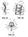
- the human spine 29comprises individual vertebrae 30 that interlock with each other to form a spinal column, shown in FIG. 1 A.
- each vertebra 30has a cylindrical bony body (vertebral body) 32 , three winglike projections (two transverse processes 33 , 35 and one spinous process 34 ), and a bony arch (neural arch) 36 .
- the bodies of the vertebrae 32are stacked one on top of the other and form the strong but flexible spinal column.
- the neural arches 36are positioned so that the space they enclose forms a tube, i.e., the spinal canal 37 .
- the spinal canal 37houses and protects the spinal cord and other neural elements.
- a fluid filled protective membrane, the dura 38covers the contents of the spinal canal.
- the spinal columnis flexible enough to allow the body to twist and bend, but sturdy enough to support and protect the spinal cord and the other neural elements.
- inter-vertebral discs 40provide flexibility to the spine and act as shock absorbers during activity.
- disorders of the spinethat may cause misalignment of the vertebrae or constriction of the spinal canal include spinal injuries, infections, tumor formation, herniation of the inter-vertebral discs (i.e., slippage or protrusion), arthritic disorders, and scoliosis.
- surgerymay be tried to either decompress the neural elements and/or fuse adjacent vertebral segments. Decompression may involve laminectomy, discectomy, or corpectomy.
- Laminectomyinvolves the removal of part of the lamina 47 , i.e., the bony roof of the spinal canal.
- Discectomyinvolves removal of the inter-vertebral discs 40 .
- Corpectomyinvolves removal of the vertebral body 32 as well as the adjacent disc spaces 40 .
- Laminectomy and corpectomyresult in central exposure of the dura 38 and its contents.
- An exposed dura 38puts the neural elements and spinal cord at risk from direct mechanical injury or scarring from overlying soft tissues.
- the surgeonneeds to stabilize the spine with a fusion. Fusion involves the fixation of two or more vertebrae. Fusion works well because it stops pain due to movement of the intervertebral discs 40 or facets 46 , immobilizes the spine, and prevents instability and or deformity of the spine after laminectomy or corpectomy.
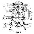
- a bone graft( 202 shown in FIG. 6 ), i.e., a solid piece of bone (1-2 inches) or bone chips, is inserted between laterally adjacent transverse processes and/or pars.
- FIG. 1 CSeveral spinal fixation systems exist for stabilizing the spine so that bony fusion is achieved.
- the majority of these fixation systemsuse either plates or rods that attach to screws inserted into the vertebral body or the pedicles 48 , shown in FIG. 1 C.
- Plate fixation systemsare more commonly used in the anterior part of the spine, i.e., vertebral bodies, while rods are the accepted standard for posterior fixation.
- plate fixation systemsare also used to fuse two adjacent vertebral segments. This construction usually consists of two longitudinal plates that are each placed laterally to connect two adjacent pedicles of the segments to be fused. This system can be extended along the sides of the spine by connecting two adjacent pedicles at a time similar to the concept of a bicycle chain.
- Current plate fixation systemsare basically designed to function in place of rods with the advantage of allowing intersegmental fixation without the need to contour a long rod across multiple segments.
- Single or multilevel segmental posterior fusionsare most commonly achieved by contouring a solid 1 ⁇ 4inch cylindrical rod and attaching it to adjacent pedicle screws on each side of the spine using various connecting assemblies.
- This longitudinal constructioncan be made more rigid by connecting the rods to each other to form an “H” configuration.
- the rod systemrequires contouring of each rod across several vertebras in many cases.
- the contouring of each roddepends on the configuration of the pedicle screws and varies from side to side in the same patient and among patients. This may add considerable time to an operation.
- Recent generations of pedicle screws and rod connectorsseek to diminish this drawback by allowing variable axes of movements in the pedicle screw recess for the rod or in the rod connectors.
- thisadds another level of complexity to the operation and often further increases the operative time.
- This increase in operative time and the complexity of the connectorsput substantial stress on the surgeon and the supporting staff.
- Even in the hands of the best spine surgeonthe rod is often not perfectly contoured to align with the pedicle screws.
- rod fixation systemis difficult to extend to higher or lower levels that need to be fused. Although there are connectors and techniques to lengthen the fixation, they tend to be difficult to use and time consuming.
- the inventionfeatures a spine fixation assembly connecting a first and second vertebra.
- the spine fixation assemblyincludes a first elongated plate having a first and second end and a second elongated plate having a first and second end.
- the first and second ends of the first plateare adapted to be attached to a first location of the first vertebra and to a second location of the second vertebra, respectively.
- the first and second ends of the second plateare adapted to be attached to a second location of the first vertebra and to a first location of the second vertebra, respectively.
- the first and second elongated platesform an X-shaped structure and may be cross-coupled.
- the locations where the ends of the plates may be attachedinclude a pedicle, transverse processes, pars, lamina, vertebral body, sacrum, lateral mass, and occiput.
- Implementations of this aspect of the inventionmay include one or more of the following features.
- the first and second elongated platesare cross-coupled and attached to each other via a screw.
- the spine fixation assemblymay further include a third elongated plate having a first and second end. The first and second ends of the third plate are adapted to be attached to the first and second locations of the first vertebra, respectively.
- the spine fixation assemblymay further include a fourth elongated plate having a first and second end. The first and second ends of the fourth plate are adapted to be attached to the first and second locations of the second vertebra, respectively.
- the first and second vertebramay be adjacent to each other.
- the ends of the elongated platesmay be attached to the locations of the vertebrae via screws or hooks.
- the screwsmay include a body portion, a first head portion connected to the body portion, a second head portion connected to the first head portion, and a head connected to the second head portion.
- the body portionhas a threaded outer surface for screwing into the locations of the vertebrae.
- the first head portionhas a serrated or a smooth outer surface for receiving an end of the elongated plates, the end having an aperture for sliding over the first head portion, and the aperture has a serrated or smooth inner surface interlocking with the serrated or smooth outer surface of the first head portion, respectively.
- the second head portionhas a threaded outer surface for receiving a washer with matching inner threads.
- the headhas a slot for receiving a screwdriver.
- the screwsmay be made of stainless steel, titanium, gold, silver, alloys thereof, or absorbable material.
- the elongated platesmay be made of metal, plastic, ceramic, bone, absorbable material, composites, or combinations thereof.
- the elongated platesmay have a length in the range of 20 millimeters to 200 millimeters.
- the elongated platesmay be flat close to the center of the plate and arch downward towards the first and second ends.
- the length of the elongated platesmay be adjustable.
- the elongated platesmay include a first and a second segment and the first and second segments are connected to each other. The first and second segments are connected to each other via a sliding mechanism, and this sliding mechanism provides an adjustable length of the elongated plates.
- the elongated platesmay include a first and a second component and the first and second component can rotate relative to each other and around a central axis passing through the center of the X-shaped structure.
- the ends of the elongated platesmay be circular and have an aperture for sliding over a screw positioned in the locations of the vertebrae.
- the aperturemay have a serrated inner surface interlocking with a serrated outer surface of the screw.
- the circular endsmay have grooves on their top and bottom surfaces. The grooves may be spaced ten degrees apart from each other.
- a washer having a grooved bottom surfacemay be adapted to be placed on the top surface of the end of the elongated plate. The washer grooves interlock with the grooves on the top surface of the end of the elongated plate.
- the elongated platesmay have a circular center and the center may have an aperture for receiving a screw.
- the aperture of the circular centermay have a threaded inner surface interlocking with a threaded outer surface of the screw.
- the top surface of the circular centermay have grooves which are spaced ten degrees apart from each other
- the inventionfeatures a spine fixation apparatus connecting a plurality of pairs of a first and a second vertebra.
- the spine fixation apparatusincludes a plurality of first elongated plates each first plate having a first and second ends, a plurality of second elongated plates having a first and second ends, and the pluralities of the first and second elongated plates form a plurality of X-shaped structures that are connected to each other.
- the first and second ends of the first platesare adapted to be attached to a plurality of first location of the plurality of first vertebra and to a plurality of second location of the plurality of second vertebra, respectively.
- the first and second ends of the second platesare adapted to be attached to a plurality of second location of the plurality of first vertebra and to a plurality of first location of the plurality of second vertebra, respectively.
- the first and second elongated platesform a plurality of X-shapes and may be cross-coupled.
- the spine fixation apparatusmay further include a third elongated plate having first and second ends, and the first and second ends of the third plate may be adapted to be attached to the first and second locations of the first vertebra, respectively.
- the spine fixation apparatusmay further include a fourth elongated plate having a first and second end, and the first and second ends of the fourth plate are adapted to be attached to the first and second locations of the second vertebra, respectively.
- the inventionfeatures a spine fixation assembly connecting a first and a second vertebra including a central structure, first, second, third and fourth elongated plates.
- the first elongated platehas a first end adapted to be attached to the central structure and a second end adapted to be attached to a first location of the first vertebra.
- the second elongated platehas a first end adapted to be attached to the central structure and a second end adapted to be attached to a second location of the first vertebra.
- the third elongated platehas a first end adapted to be attached to the central structure and a second end adapted to be attached to a first location of the second vertebra
- the fourth elongated platehas a first end adapted to be attached to the central structure and a second end adapted to be attached to a second location of the second vertebra.
- the central structuremay have a circular or rectangular shape.
- the elongated platesmay have adjustable length and the length may be in the range of 10 millimeters to 200 millimeters.
- the second ends of the elongated platesmay be attached to the locations of the vertebrae via screws or hooks.
- the first ends of the elongated platesmay be attached to the central structure allowing rotational movement around an axis passing through the central structure and are secured via screws or a ring.
- the inventionfeatures a spine fixation method connecting a first and second vertebra including the following steps. First, providing a first elongated plate having a first and second ends and attaching the first and second ends of the first plate to a first location of the first vertebra and to a second location of the second vertebra, respectively. Next, providing a second elongated plate having a first and second ends and attaching the first and second ends of the second plate to a second location of the first vertebra and to a first location of the second vertebra, respectively.
- the first and second platesform an X-shaped structure.
- the methodmay further include cross-coupling the first and second elongated plates.
- the methodmay further include providing a third elongated plate having first and second ends and attaching the first and second ends of the third plate to the first and second locations of the first vertebra, respectively.
- the methodmay further include providing a fourth elongated plate having first and second ends and attaching the first and second ends of the fourth plate to the first and second locations of the second vertebra, respectively.
- the inventionfeatures a spine fixation method connecting a first and second vertebra including the following steps. First attaching first and second screws to first and second locations of the first and second vertebra, respectively. Then, attaching third and fourth screws to second and first locations of the first and second vertebra, respectively. Next, providing a first elongated plate having a first and second ends and attaching the first and second ends of the first elongated plate to the first location of the first vertebra and to a second location of the second vertebra via the first and second screws, respectively.
- first and second elongated plateshaving a first and second ends and attaching the first and second ends of the second elongated plate to the second location of the first vertebra and to the first location of the second vertebra via the third and fourth screws, respectively.
- the first and second elongated platesform an X-shaped structure.
- cross-coupling the first and second elongated platesby placing a central screw through the center of he X-shaped structure; and tightening of all said screws.
- the methodmay further include adjusting the length of the first and second elongated plates.
- the inventionfeatures a spine fixation method connecting a first and second vertebra including the following step. First, attaching first and second screws to first and second locations of the first and second vertebra, respectively. Next, attaching third and fourth screws to second and first locations of the first and second vertebra, respectively. Then, providing a first elongated plate having a first and second ends and a center, and attaching the first and second ends of the first elongated plate to the first location of the first vertebra and to a second location of the second vertebra via the first and second screws, respectively.
- the methodmay further include adjusting the length of the first, second, and third elongated plates.
- the inventionfeatures a spine fixation method connecting a first and second vertebra including the following steps. First, attaching first and second screws to first and second locations of the first vertebra, respectively. Next, attaching third and fourth screws to first and second locations of the second vertebra, respectively. Then providing a central structure having fifth, sixth, seventh and eighth screws. Next, providing a first elongated plate having first and second ends, and attaching the first and second ends of the first elongated plate to the first location of the first vertebra and the central structure via the first and fifth screws, respectively.
- the methodmay further include adjusting the length of the first, second, third, and fourth elongated plates.
- the inventionfeatures a spine fixation method connecting a first and second vertebra including the following steps. First attaching first and second screws to first and second locations of the first vertebra, respectively. Next, attaching third and fourth screws to first and second locations of the second vertebra, respectively. Next, providing a pair of first and second elongated plates forming an X-shaped structure and then placing the X-shaped structure over the first and second vertebra. Next, attaching a first and a second end of the first elongated plate to the first location of the first vertebra and the second location of the second vertebra via the first and fourth screws, respectively.
- the methodmay further include adjusting the length of the first and second elongated plates.
- the spine fixation assembly of this inventionprovides a rigid and compact structure. It has low side and front profiles and does not interfere with the lateral soft tissues and bones.
- the basic X-shaped structureincreases the available area for bone grafting and provides easy access to the transverse processes 230 , 232 and pars 234 , 236 for bone graft 202 , 204 placement after implanting the spine fixation assembly, shown in FIG. 6 .
- the flexibility in length and orientation of the platesallows the assembly to be adapted to non-symmetric spinal anatomies.
- the basic X-shape structureis repeated to extend the spine fixation in either caudad or cephalad directions either at the initial surgery or during revision.
- the modular platescouple to each other and the pedicle screws without the need to apply excessive retraction on the surrounding soft tissues. This reduces the injury risk of the surrounding soft tissue, bones, and neural elements during placement of the plates. Furthermore, the cross-coupled plates cover and protect the midline and spinal canal of the patient from direct injury or possible scarring from overlying soft tissues.
- FIG. 1Ais a side view of the human spinal column
- FIG. 1Bis an enlarged view of area A of FIG. 1 A:
- FIG. 1Cis an axial cross-sectional view of a lumbar vertebra
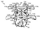
- FIG. 2Ais a schematic posterior view of two adjacent vertebrae rigidly connected to each other via a spine fixation assembly according to this invention
- FIG. 2Bis a schematic side view of FIG. 2A;
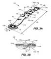
- FIG. 3Ais a perspective view of elongated plate 110 of FIG. 2A;
- FIG. 3Bis a cross-sectional side view of area 183 of FIG. 3A;
- FIG. 3Cis a partial top view of the elongated plate 110 of FIG. 3 A.
- FIG. 3Dis a side view of the elongated plate 110 of FIG. 3A;
- FIG. 4is an exploded partial view of the spine fixation assembly of FIG. 2A;
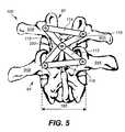
- FIG. 5is a schematic posterior view of a spine fixation assembly connecting two non-symmetric (i.e., scoliotic) adjacent vertebrae;
- FIG. 6is a perspective posterior view of the spinal column and the modular spine fixation assembly of this invention connecting three adjacent vertebrae;
- FIG. 7is a schematic diagram of an alternative spine fixation assembly according to this invention.
- FIG. 8is a schematic diagram of another alternative spine fixation assembly according to this invention.
- FIG. 9is a flow diagram depicting the method of applying the spine fixation assembly of this invention.
- FIG. 10is a flow diagram depicting another embodiment of the method of applying the spine fixation assembly of this invention.
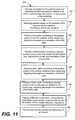
- FIG. 11is a flow diagram depicting another embodiment of the method of applying the spine fixation assembly of this invention.
- FIG. 12is a flow diagram depicting another embodiment of the method of applying the spine fixation assembly of this invention.
- a spine fixation assembly 100connects vertebra 92 to adjacent vertebra 94 .
- the spine fixation assembly 100includes elongated plates 110 , 112 , 114 and 116 .
- Plates 110 , 112 , 114 and 116have circular ends 110 a and 110 b , 112 a and 112 b , 114 a and 114 b , 116 a and 116 b , respectively.
- Plates 110 and 112are cross-coupled at midpoint 108 forming a X-shaped structure.
- the ends 110 a , 110 b of plate 110are secured to diagonally opposite pedicles 92 A and 94 B of adjacent vertebrae 92 and 94 via pedicle screws 120 a and 122 b , respectively.
- ends 112 a , 112 b of plate 112are secured to diagonally opposite pedicles 92 B and 94 A of the adjacent vertebrae 92 and 94 via pedicle screws 120 b and 122 a , respectively.
- Pedicle screws 120 a , 120 b , 122 a , 122 bare inserted into the vertebral body through the pedicles 92 A, 94 B, 92 B, 94 A, respectively, as shown in FIGS. 2A and 2B.
- Plates 110 and 112are also attached to each other in the midpoint 108 via a center screw 125 and a locking threaded nut 123 , shown in FIG. 4 .
- the spine fixation assembly 100further includes transverse plates 114 and 116 with circular ends 114 a , 114 b , and 116 a , 116 b , respectively.
- Ends 114 a and 114 b of plate 114are secured to opposite pedicles 92 A and 92 B of vertebra 92 via pedicle screws 120 a and 120 b , respectively.
- ends 116 a and 116 bare secured to opposite pedicles 94 A and 94 B of vertebra 94 via pedicle screws 122 a and 122 b , respectively.
- Transverse plates 114 and 116provide additional structural support to the X-shaped structure.
- elongated plate 110comprises circular ends 110 a , 110 b , a circular center 109 , a first elongated segment 105 , and a second elongated segment 107 .
- Segment 105extends from the circular center 109 to circular end 110 a and segment 107 extends from the circular center 109 to circular end 110 b .
- Ends 110 a , 110 b and circular center 109have apertures 152 a , 152 b , and 194 , respectively.
- Aperture 194has a threaded inner surface for locking a threaded screw 125 , shown in FIG. 4 .
- Apertures 152 a and 152 bhave serrated inner surfaces for receiving a pedicle screw with matching longitudinal serrations 143 , shown in FIG. 4 .
- the top and bottom surfaces of circular ends 110 a , 110 b , and the top surface of circular center 109have radial extending grooves 88 , shown in FIG. 3 D.
- Grooves 88define ten-degree arcs, thus allowing the plates 110 , 112 , 114 , 116 to rotate relative to each other by ten degree steps.
- segment 107comprises of two separate plates 111 A and 111 B that overlap at area 183 .
- Plates 111 A and 111 Bhave overlapping elongated slots 184 A and 184 B, respectively, extending through the thickness of the corresponding plate.
- a housing 182slides over the overlapping plates 111 A and 111 B.
- Housing 182has an elongated slot 186 that runs through the thickness of the housing 182 and is aligned with the elongated slots 184 A and 184 B.
- the length 160 of plate 110is 80 millimeters and it can be increased or decreased up to 10 millimeters via the combined sliding mechanisms 180 .
- the width 162 of plate 110is 8 millimeters and the thickness 164 is 4 millimeters.
- the diameter 161 of the circular center 109is 10 millimeters and the diameter 163 of the circular ends is 10 millimeters.
- the width 162 of plate 110may taper from 10 millimeters close to the circular center 109 to 8 millimeters close to the circular end 110 b , shown in FIG.
- Segments 105 and 107may be flat close to the center 109 and then gently curve downwards before flattening out at the circular ends 110 a , 110 b or curve more sharply closer to the ends 110 a and 110 b to clear the facet joints before flattening out at the circular ends 100 a and 110 b shown in FIG. 3 D.
- the curvature of the plate 110provides space between the spine fixation assembly and the spinal canal and is also designed to clear the facets 46 laterally. This arrangement covers the central spinal canal and may protect the neural elements from scar tissue formation or mechanical damage.
- pedicle screw 122 bcomprises a body portion 140 , a first head portion 142 , a second head portion 144 , and a head 146 .
- the body portion 140 of pedicle screw 122 bhas helical threads on its exterior surface and screws into the vertebral body through the pedicle 94 B.
- a hexagonal screwdriver(not shown) is inserted into a slot 148 formed on the head 146 of the pedicle screw 122 a and is used to drive the screw 122 b into the vertebral body.
- the first head portion 142is directly above the body portion 140 and has a smooth or serrated outer surface for receiving the end 110 b of plate 110 .
- End 110 bhas an aperture 152 b that allows end 110 a to slide over the pedicle screw 122 b .
- the second head portion 144has a threaded outer surface for receiving washer 154 .
- Washer 154slides over the head 146 of the pedicle screw 112 b and screws around the threaded outer surface of the second head portion 144 , thus securely attaching the end 110 b of plate 110 to pedicle screw 122 b .
- the end 116 b of plate 116is also attached to pedicle screw 122 b in a similar way, shown in FIG. 2 A.
- pedicle screw 122 ahas a length 220 of 57 millimeters and a diameter 222 of 6.5 millimeters.
- elongated plate 112comprises two separate plates 113 and 115 .
- Plate 13has an end 11 3 a overlapping with end 115 a of plate 115 and with circular center 109 of plate 110 .
- End 113 a , end 115 a , and circular center 109have overlapping aligned apertures 190 , 192 , and 194 , respectively.
- a screw 125is threaded through the aligned apertures 190 , 192 , and 194 and is secured by a threaded nut or a washer 123 .
- plates 113 and 115have a length 159 of 40 millimeters. Length 159 can be adjusted via the sliding mechanism 180 , described above. In one example, screw 125 has a length 223 of 16 millimeters.
- plates 113 and 115are rotated relative to each other and around the central axis 250 of the spine fixation assembly 100 to accommodate non-symmetric vertebrae and pedicle locations as in scoliosis.
- circular ends 113 a and 115 ahave grooves 88 that define ten degree arcs. Grooves 88 allow plates 113 and 115 to rotate by ten degree steps until the desired orientation with respect to the pedicle screw is reached. The desired orientation is finally secured via screw 125 and washer 123 , shown in FIG. 4 .
- Transverse plates 114 and 116connect to opposite pedicles 92 A, 92 B of vertebra 92 and opposite pedicles 94 A, 94 B of vertebra 94 , respectively.
- Transverse plates 114 , 116provide structural support and rigidity to the spine fixation assembly 100 .
- transverse plates 114 , 116have a length 165 of 40 millimeters.
- the basic spine fixation assembly of FIG. 2Ais repeated to connect adjacent vertebrae 92 , 94 and 96 comprising the spine 90 .
- the top and bottom pedicles 92 A, 92 B and 96 A, 96 Bare connected with transverse plates 114 and 116 , respectively.
- the basic X-shape structuremay be repeated to extend the spine fixation in either caudad 272 or cephalad 270 directions.
- the modular structure of the spine fixation assembly 100allows a surgeon to correct spinal deformities over any distance and orientation along the entire spine 29 .
- plates 302 , 304 , 306 , and 308extend radially from a central structure 300 and are attached to pedicles 92 A, 92 B, 94 A, and 94 B, respectively.
- the length of each plate 302 , 304 , 306 , 308may be varied via the sliding mechanism 180 described above. Plates 302 , 304 , 306 and 308 may also be rotated relative to the central axis 350 . The final orientation is secured via the central ring 310 .
- Central structure 300may have a circular (FIG. 7) or square cross-section (FIG. 8 ).
- a method 400 of using the spine fixation assembly 100comprises the following steps. Opening an incision in the patient's back, exposing the first and second vertebrae and their corresponding transverse processes to be fused, and performing laminectomy posteriorly or anterior discectomy or corpectomy of the two vertebrae ( 410 ). Placing pedicle screws within the pedicles of the first and second vertebra ( 420 ). Placing a first plate connecting two diagonally across pedicle screws on the first and second vertebra, adjusting the length and orientation of the first plate, and placing a center screw through the center of the first plate ( 430 ).
- an alternative method of using the spine fixation assembly 100comprises the following steps. Opening an incision in the patient's back, exposing the first and second vertebrae and their corresponding transverse processes to be fused, and performing laminectomy posteriorly or anterior discectomy or corpectomy of the two vertebrae ( 412 ). Placing four pedicle screws within the first and second pedicles of the first and second vertebra ( 422 ). Placing a first plate connecting two diagonally across pedicle screws on the first and second vertebra, adjusting the length and orientation of the first plate, and placing a center screw through an aperture at the center of the fist plate ( 432 ).
- an alternative method of using the spine fixation assembly 100comprises the following steps. First opening an incision in the patient's back, exposing the first and second vertebrae and their corresponding transverse processes to be fused and performing laminectomy posteriorly or anterior discectomy or corpectomy of the two vertebrae ( 414 ). Placing first, second, third and fourth pedicle screws within the first and second pedicles of the first and second vertebra, respectively, and providing a central structure having fifth, sixth, seventh and eighth screws ( 424 ).
- an alternative method of using the spine fixation assembly 100comprises the following steps. First opening an incision in the patient's back, exposing the first and second vertebrae and their corresponding transverse processes to be fused and performing laminectomy posteriorly or anterior discectomy or corpectomy of the two vertebrae ( 416 ). Placing first, second, third and fourth pedicle screws within the first and second pedicles of the first and second vertebra, respectively ( 426 ). Providing a pair of cross-coupled first and second elongated plates forming an X-shaped structure; adjusting the length of the elongated plates ( 436 ). Placing the X-shaped structure over the first and second vertebra to be fused ( 446 ).
- plate 110may also comprise two separate segments which are rotated relative to the central axis 250 in order to accommodate non-symmetric vertebrae arrangements and pedicle screw orientation.
- the ends of platesmay be secured to pedicle screws via connectors.
- the ends of platesmay be attached to the vertebrae via hooks.
- Other locations where screws or hooks may be anchored for attaching the fixation assembly of this inventioninclude the transverse processes 33 , 35 , the lamina 47 , the vertebral body 32 , the sacrum 24 , lateral mass 28 and the occiput 26 , shown in FIGS. 1A and 1C.
- the sliding mechanism 180may be also designed to accommodate rotational motion of plates 111 A and 11 B.
- Plates 110 , 112may have integral screws or bolts with a threaded end.
- plate 110has a bolt or screw extending from the center of the circular center 109 , instead of a central aperture 194 .
- the boltis threaded through the central aperture of plate 112 and a locking nut is placed over the threaded end of the bolt for attaching the two plates together.
- the assemblymay be also constructed with rods instead of plates or a combination of rods and plates.
- Plates 112 , 113 , 110 ; 111 , 114 , 116may be manufactured from a variety of materials including among others stainless steel, titanium, nickel, composites, ceramics, plastic, bone, absorbable material or combination thereof.
- Pedicle screwsmay be manufactured from a variety of materials including among others stainless steel, titanium, gold, silver or alloys thereof.
- any two vertebras, not necessarily adjacentmay be fused together with the spine fixation system of this invention.
Landscapes
- Health & Medical Sciences (AREA)
- Orthopedic Medicine & Surgery (AREA)
- Life Sciences & Earth Sciences (AREA)
- Neurology (AREA)
- Surgery (AREA)
- Heart & Thoracic Surgery (AREA)
- Engineering & Computer Science (AREA)
- Biomedical Technology (AREA)
- Nuclear Medicine, Radiotherapy & Molecular Imaging (AREA)
- Medical Informatics (AREA)
- Molecular Biology (AREA)
- Animal Behavior & Ethology (AREA)
- General Health & Medical Sciences (AREA)
- Public Health (AREA)
- Veterinary Medicine (AREA)
- Surgical Instruments (AREA)
- Prostheses (AREA)
Abstract
Description
Claims (66)
Priority Applications (3)
| Application Number | Priority Date | Filing Date | Title |
|---|---|---|---|
| US10/185,477US6626909B2 (en) | 2002-02-27 | 2002-06-28 | Apparatus and method for spine fixation |
| EP03716113AEP1487360A4 (en) | 2002-02-27 | 2003-02-24 | Apparatus and method for spine fixation |
| PCT/US2003/005242WO2003071960A1 (en) | 2002-02-27 | 2003-02-24 | Apparatus and method for spine fixation |
Applications Claiming Priority (2)
| Application Number | Priority Date | Filing Date | Title |
|---|---|---|---|
| US35996802P | 2002-02-27 | 2002-02-27 | |
| US10/185,477US6626909B2 (en) | 2002-02-27 | 2002-06-28 | Apparatus and method for spine fixation |
Publications (2)
| Publication Number | Publication Date |
|---|---|
| US20030163132A1 US20030163132A1 (en) | 2003-08-28 |
| US6626909B2true US6626909B2 (en) | 2003-09-30 |
Family
ID=27760109
Family Applications (1)
| Application Number | Title | Priority Date | Filing Date |
|---|---|---|---|
| US10/185,477Expired - LifetimeUS6626909B2 (en) | 2002-02-27 | 2002-06-28 | Apparatus and method for spine fixation |
Country Status (3)
| Country | Link |
|---|---|
| US (1) | US6626909B2 (en) |
| EP (1) | EP1487360A4 (en) |
| WO (1) | WO2003071960A1 (en) |
Cited By (111)
| Publication number | Priority date | Publication date | Assignee | Title |
|---|---|---|---|---|
| US20020133155A1 (en)* | 2000-02-25 | 2002-09-19 | Ferree Bret A. | Cross-coupled vertebral stabilizers incorporating spinal motion restriction |
| US20050102028A1 (en)* | 2003-11-07 | 2005-05-12 | Uri Arnin | Spinal prostheses |
| US20050203518A1 (en)* | 2004-03-05 | 2005-09-15 | Biedermann Motech Gmbh | Stabilization device for the dynamic stabilization of vertebrae or bones and rod like element for such a stabilization device |
| US20050228381A1 (en)* | 2004-04-09 | 2005-10-13 | Kirschman David L | Disk augmentation system and method |
| US20060036259A1 (en)* | 2004-08-03 | 2006-02-16 | Carl Allen L | Spine treatment devices and methods |
| US20060058790A1 (en)* | 2004-08-03 | 2006-03-16 | Carl Allen L | Spinous process reinforcement device and method |
| US20060079896A1 (en)* | 2004-09-30 | 2006-04-13 | Depuy Spine, Inc. | Methods and devices for posterior stabilization |
| US20060084991A1 (en)* | 2004-09-30 | 2006-04-20 | Depuy Spine, Inc. | Posterior dynamic stabilizer devices |
| US7041136B2 (en) | 2000-11-29 | 2006-05-09 | Facet Solutions, Inc. | Facet joint replacement |
| US20060149230A1 (en)* | 2004-12-30 | 2006-07-06 | Kwak Seungkyu Daniel | Posterior stabilization system |
| US20060149229A1 (en)* | 2004-12-30 | 2006-07-06 | Kwak Seungkyu Daniel | Artificial facet joint |
| US7074237B2 (en) | 2000-12-13 | 2006-07-11 | Facet Solutions, Inc. | Multiple facet joint replacement |
| US20060161154A1 (en)* | 2004-12-10 | 2006-07-20 | Mcafee Paul | Prosthetic spinous process and method |
| US7090698B2 (en) | 2001-03-02 | 2006-08-15 | Facet Solutions | Method and apparatus for spine joint replacement |
| US20060217723A1 (en)* | 2005-03-11 | 2006-09-28 | Suh Sean S | Translational scissor plate fixation system |
| US20060241610A1 (en)* | 2005-04-08 | 2006-10-26 | Sdgi Holdings, Inc. | Interspinous process spacer |
| US20060276787A1 (en)* | 2005-05-26 | 2006-12-07 | Accin Corporation | Pedicle screw, cervical screw and rod |
| US20060282075A1 (en)* | 2005-06-10 | 2006-12-14 | Depuy Spine, Inc. | Posterior dynamic stabilization x-device |
| US20070005062A1 (en)* | 2005-06-20 | 2007-01-04 | Sdgi Holdings, Inc. | Multi-directional spinal stabilization systems and methods |
| US20070079517A1 (en)* | 2004-04-22 | 2007-04-12 | Augostino Teena M | Facet joint prosthesis measurement and implant tools |
| US20070173823A1 (en)* | 2006-01-18 | 2007-07-26 | Sdgi Holdings, Inc. | Intervertebral prosthetic device for spinal stabilization and method of implanting same |
| US20070238069A1 (en)* | 2006-04-10 | 2007-10-11 | Scott Lovald | Osteosynthesis plate, method of customizing same, and method for installing same |
| US20080015585A1 (en)* | 2005-03-22 | 2008-01-17 | Philip Berg | Minimally invasive spine restoration systems, devices, methods and kits |
| US20080033438A1 (en)* | 2006-08-04 | 2008-02-07 | Roy Frizzell | Cervical Saddle Plate |
| US20080039847A1 (en)* | 2006-08-09 | 2008-02-14 | Mark Piper | Implant and system for stabilization of the spine |
| US20080058805A1 (en)* | 2006-08-28 | 2008-03-06 | Microdexterity Systems, Inc. | Spinal fusion implant |
| US20080119845A1 (en)* | 2006-09-25 | 2008-05-22 | Archus Orthopedics, Inc. | Facet replacement device removal and revision systems and methods |
| US20080177308A1 (en)* | 2004-10-04 | 2008-07-24 | Archus Orthopedics, Inc. | Polymeric joint complex and methods of use |
| US20080195151A1 (en)* | 2007-02-13 | 2008-08-14 | Ferree Bret A | Methods of Bone, Joint, and Ligament Reconstruction |
| US20080208256A1 (en)* | 2006-11-10 | 2008-08-28 | Lanx, Llc | Pedicle based spinal stabilization with adjacent vertebral body support |
| US20080249568A1 (en)* | 2004-10-25 | 2008-10-09 | Kuiper Mark K | Crossbar Spinal Prosthesis Having a Modular Design and Systems for Treating Spinal Pathologies |
| US20080287959A1 (en)* | 2005-09-26 | 2008-11-20 | Archus Orthopedics, Inc. | Measurement and trialing system and methods for orthopedic device component selection |
| US20090024165A1 (en)* | 2007-07-17 | 2009-01-22 | Ferree Bret A | Methods of annulus and ligament reconstruction using flexible devices |
| US7507242B2 (en) | 2004-06-02 | 2009-03-24 | Facet Solutions | Surgical measurement and resection framework |
| US20090105755A1 (en)* | 2007-10-22 | 2009-04-23 | Warsaw Orthopedics, Inc. | Apparatus and method for connecting spinal fixation systems together |
| US20090131984A1 (en)* | 2007-11-19 | 2009-05-21 | Linares Miguel A | Spine support implant including inter vertebral insertable fluid ballastable insert and inter-vertebral web retaining harnesses |
| WO2009064419A1 (en)* | 2007-11-12 | 2009-05-22 | Dong Myung Jeon | Dynamic spinal stabilization device |
| US7566345B1 (en) | 2001-03-01 | 2009-07-28 | Facet Solutions, Inc | Prosthesis for the replacement of a posterior element of a vertebra |
| US7588590B2 (en) | 2003-12-10 | 2009-09-15 | Facet Solutions, Inc | Spinal facet implant with spherical implant apposition surface and bone bed and methods of use |
| US20090248023A1 (en)* | 2008-03-31 | 2009-10-01 | Cochlear Limited | Mechanical fixation system for a prosthetic device |
| US20090248026A1 (en)* | 2001-03-28 | 2009-10-01 | Moximed, Inc. | Bone fixated, articulated joint load control device |
| US7608104B2 (en) | 2003-05-14 | 2009-10-27 | Archus Orthopedics, Inc. | Prostheses, tools and methods for replacement of natural facet joints with artifical facet joint surfaces |
| US7674293B2 (en) | 2004-04-22 | 2010-03-09 | Facet Solutions, Inc. | Crossbar spinal prosthesis having a modular design and related implantation methods |
| US7691145B2 (en) | 1999-10-22 | 2010-04-06 | Facet Solutions, Inc. | Prostheses, systems and methods for replacement of natural facet joints with artificial facet joint surfaces |
| US7708765B2 (en) | 2004-08-03 | 2010-05-04 | K Spine, Inc. | Spine stabilization device and method |
| US7722647B1 (en) | 2005-03-14 | 2010-05-25 | Facet Solutions, Inc. | Apparatus and method for posterior vertebral stabilization |
| US20100161056A1 (en)* | 2008-12-19 | 2010-06-24 | Depuy Spine, Inc. | Methods and devices for expanding a spinal canal |
| US7763052B2 (en) | 2003-12-05 | 2010-07-27 | N Spine, Inc. | Method and apparatus for flexible fixation of a spine |
| US7766943B1 (en) | 2005-08-11 | 2010-08-03 | Medicine Lodge Inc. | Modular percutaneous spinal fusion system and method |
| US20100234958A1 (en)* | 2007-11-19 | 2010-09-16 | Linares Medical Devices, Llc | Combination spacer insert and support for providing inter-cervical vertebral support |
| US7815665B2 (en) | 2003-09-24 | 2010-10-19 | N Spine, Inc. | Adjustable spinal stabilization system |
| US7854752B2 (en) | 2004-08-09 | 2010-12-21 | Theken Spine, Llc | System and method for dynamic skeletal stabilization |
| US7867256B2 (en) | 2004-10-07 | 2011-01-11 | Synthes Usa, Llc | Device for dynamic stabilization of bones or bone fragments |
| US7896902B2 (en) | 2006-04-05 | 2011-03-01 | Dong Myung Jeon | Multi-axial double locking bone screw assembly |
| US7914556B2 (en) | 2005-03-02 | 2011-03-29 | Gmedelaware 2 Llc | Arthroplasty revision system and method |
| US20110106087A1 (en)* | 2009-10-30 | 2011-05-05 | Gamache Thomas J | Bone Plate Holder |
| US20110106083A1 (en)* | 2009-10-30 | 2011-05-05 | Voellmicke John C | Laminoplasty Plates and Methods of Expanding the Spinal Canal |
| US20110106084A1 (en)* | 2009-10-30 | 2011-05-05 | Thomas J Gamache | Bone Graft Loading Instruments and Methods of Connecting a Bone Graft to a Bone Plate |
| US20110106169A1 (en)* | 2009-10-30 | 2011-05-05 | Zalenski Edward B | Bone Plate Holder |
| US7959653B2 (en) | 2004-09-03 | 2011-06-14 | Lanx, Inc. | Spinal rod cross connector |
| US7959679B2 (en) | 1999-08-18 | 2011-06-14 | Intrinsic Therapeutics, Inc. | Intervertebral anulus and nucleus augmentation |
| US7972337B2 (en) | 2005-12-28 | 2011-07-05 | Intrinsic Therapeutics, Inc. | Devices and methods for bone anchoring |
| US7988710B2 (en) | 2003-09-24 | 2011-08-02 | N Spine, Inc. | Spinal stabilization device |
| US7993370B2 (en) | 2003-09-24 | 2011-08-09 | N Spine, Inc. | Method and apparatus for flexible fixation of a spine |
| US7993373B2 (en) | 2005-02-22 | 2011-08-09 | Hoy Robert W | Polyaxial orthopedic fastening apparatus |
| US8002836B2 (en) | 1999-08-18 | 2011-08-23 | Intrinsic Therapeutics, Inc. | Method for the treatment of the intervertebral disc anulus |
| US8021425B2 (en)* | 1999-08-18 | 2011-09-20 | Intrinsic Therapeutics, Inc. | Versatile method of repairing an intervertebral disc |
| US8025681B2 (en) | 2006-03-29 | 2011-09-27 | Theken Spine, Llc | Dynamic motion spinal stabilization system |
| US8034081B2 (en) | 2007-02-06 | 2011-10-11 | CollabComl, LLC | Interspinous dynamic stabilization implant and method of implanting |
| US8114158B2 (en) | 2004-08-03 | 2012-02-14 | Kspine, Inc. | Facet device and method |
| US20120095510A1 (en)* | 2010-10-18 | 2012-04-19 | Raj Nihalani | Cross connectors |
| US8162979B2 (en) | 2007-06-06 | 2012-04-24 | K Spine, Inc. | Medical device and method to correct deformity |
| US8187303B2 (en) | 2004-04-22 | 2012-05-29 | Gmedelaware 2 Llc | Anti-rotation fixation element for spinal prostheses |
| US8206418B2 (en) | 2007-01-10 | 2012-06-26 | Gmedelaware 2 Llc | System and method for facet joint replacement with detachable coupler |
| WO2012054356A3 (en)* | 2010-10-18 | 2012-07-19 | Spinofix, Inc. | Cross connectors |
| US8231655B2 (en) | 2003-07-08 | 2012-07-31 | Gmedelaware 2 Llc | Prostheses and methods for replacement of natural facet joints with artificial facet joint surfaces |
| US8231678B2 (en) | 1999-08-18 | 2012-07-31 | Intrinsic Therapeutics, Inc. | Method of treating a herniated disc |
| US8323341B2 (en) | 2007-09-07 | 2012-12-04 | Intrinsic Therapeutics, Inc. | Impaction grafting for vertebral fusion |
| US8357182B2 (en) | 2009-03-26 | 2013-01-22 | Kspine, Inc. | Alignment system with longitudinal support features |
| US8398681B2 (en) | 2004-08-18 | 2013-03-19 | Gmedelaware 2 Llc | Adjacent level facet arthroplasty devices, spine stabilization systems, and methods |
| US8409254B2 (en) | 2003-05-14 | 2013-04-02 | Gmedelaware 2 Llc | Prostheses, tools and methods for replacement of natural facet joints with artificial facet joint surfaces |
| US8449576B2 (en) | 2006-06-28 | 2013-05-28 | DePuy Synthes Products, LLC | Dynamic fixation system |
| US8454612B2 (en) | 2007-09-07 | 2013-06-04 | Intrinsic Therapeutics, Inc. | Method for vertebral endplate reconstruction |
| US8491641B2 (en) | 2010-09-28 | 2013-07-23 | Spinofix, Inc. | Pedicle screws and dynamic adaptors |
| US8556936B2 (en) | 2000-11-29 | 2013-10-15 | Gmedelaware 2 Llc | Facet joint replacement |
| US8562649B2 (en) | 2004-02-17 | 2013-10-22 | Gmedelaware 2 Llc | System and method for multiple level facet joint arthroplasty and fusion |
| US8594356B2 (en) | 2010-04-29 | 2013-11-26 | Cochlear Limited | Bone conduction device having limited range of travel |
| US8623057B2 (en) | 2003-09-24 | 2014-01-07 | DePuy Synthes Products, LLC | Spinal stabilization device |
| US8675930B2 (en) | 2004-04-22 | 2014-03-18 | Gmedelaware 2 Llc | Implantable orthopedic device component selection instrument and methods |
| US8702755B2 (en) | 2006-08-11 | 2014-04-22 | Gmedelaware 2 Llc | Angled washer polyaxial connection for dynamic spine prosthesis |
| US8758439B2 (en) | 2007-11-19 | 2014-06-24 | Linares Medical Devices, Llc | Spine support implant including inter vertebral insertable fluid ballastable insert and inter-vertebral web retaining harnesses |
| US8764801B2 (en) | 2005-03-28 | 2014-07-01 | Gmedelaware 2 Llc | Facet joint implant crosslinking apparatus and method |
| US8828058B2 (en) | 2008-11-11 | 2014-09-09 | Kspine, Inc. | Growth directed vertebral fixation system with distractible connector(s) and apical control |
| US8900273B2 (en) | 2005-02-22 | 2014-12-02 | Gmedelaware 2 Llc | Taper-locking fixation system |
| US8920472B2 (en) | 2011-11-16 | 2014-12-30 | Kspine, Inc. | Spinal correction and secondary stabilization |
| US8992576B2 (en) | 2008-12-17 | 2015-03-31 | DePuy Synthes Products, LLC | Posterior spine dynamic stabilizer |
| US8998961B1 (en) | 2009-02-26 | 2015-04-07 | Lanx, Inc. | Spinal rod connector and methods |
| US9056016B2 (en) | 2003-12-15 | 2015-06-16 | Gmedelaware 2 Llc | Polyaxial adjustment of facet joint prostheses |
| US9168071B2 (en) | 2009-09-15 | 2015-10-27 | K2M, Inc. | Growth modulation system |
| US9204908B2 (en) | 2007-07-26 | 2015-12-08 | Dynamic Spine, Llc | Segmental orthopedic device for spinal elongation and for treatment of scoliosis |
| US9204899B2 (en) | 2007-07-26 | 2015-12-08 | Dynamic Spine, Llc | Segmental orthopedic device for spinal elongation and for treatment of scoliosis |
| US9277950B2 (en) | 2010-06-10 | 2016-03-08 | Dynamic Spine, Llc | Low-profile, uniplanar bone screw |
| US9333009B2 (en) | 2011-06-03 | 2016-05-10 | K2M, Inc. | Spinal correction system actuators |
| US9451987B2 (en) | 2011-11-16 | 2016-09-27 | K2M, Inc. | System and method for spinal correction |
| US9468468B2 (en) | 2011-11-16 | 2016-10-18 | K2M, Inc. | Transverse connector for spinal stabilization system |
| US9468471B2 (en) | 2013-09-17 | 2016-10-18 | K2M, Inc. | Transverse coupler adjuster spinal correction systems and methods |
| US9468469B2 (en) | 2011-11-16 | 2016-10-18 | K2M, Inc. | Transverse coupler adjuster spinal correction systems and methods |
| US9706947B2 (en) | 1999-08-18 | 2017-07-18 | Intrinsic Therapeutics, Inc. | Method of performing an anchor implantation procedure within a disc |
| US10702311B2 (en) | 2011-11-16 | 2020-07-07 | K2M, Inc. | Spinal correction and secondary stabilization |
| US20210322062A1 (en)* | 2020-03-11 | 2021-10-21 | Chaim Rogozinski | System and Method for the Treatment of Spinal Conditions |
| US20230329757A1 (en)* | 2020-12-17 | 2023-10-19 | Institute For Spine & Scoliosis, P.A. | Method for improved spinal correction surgery implementing non-fusion anterior scoliosis correction techniques |
Families Citing this family (30)
| Publication number | Priority date | Publication date | Assignee | Title |
|---|---|---|---|---|
| US7588589B2 (en)* | 2003-03-20 | 2009-09-15 | Medical Designs Llc | Posterior spinal reconstruction system |
| ES2295708T3 (en)* | 2003-09-08 | 2008-04-16 | Synthes Gmbh | DEVICE FOR OSEA FIXATION. |
| US8167917B2 (en)* | 2003-09-24 | 2012-05-01 | Spinefrontier Lls | Apparatus and method for spine fixation |
| US20070225713A1 (en)* | 2004-10-20 | 2007-09-27 | Moti Altarac | Systems and methods for posterior dynamic stabilization of the spine |
| US7621942B2 (en)* | 2005-03-21 | 2009-11-24 | Zimmer Spine, Inc. | Variable geometry occipital fixation plate |
| US8430911B2 (en)* | 2005-12-14 | 2013-04-30 | Spinefrontier Inc | Spinous process fixation implant |
| US20070270820A1 (en)* | 2006-04-26 | 2007-11-22 | Sdgi Holdings, Inc. | Revision fixation plate and method of use |
| US20070299441A1 (en)* | 2006-06-09 | 2007-12-27 | Zachary M. Hoffman | Adjustable Occipital Plate |
| US7901433B2 (en) | 2006-10-04 | 2011-03-08 | Zimmer Spine, Inc. | Occipito-cervical stabilization system and method |
| US8147527B2 (en)* | 2006-11-28 | 2012-04-03 | Zimmer Spine, Inc. | Adjustable occipital plate |
| US8636737B2 (en)* | 2006-12-27 | 2014-01-28 | Zimmer Spine, Inc. | Modular occipital plate |
| US8246662B2 (en)* | 2006-12-27 | 2012-08-21 | Zimmer Spine, Inc. | Modular occipital plate |
| US8506567B2 (en) | 2009-02-04 | 2013-08-13 | Lanx, Inc. | Occipital plate fixation system |
| US8518042B2 (en)* | 2010-10-19 | 2013-08-27 | Biomet Manufacturing, Llc | Orthopedic plate assembly for a distal radius having re-contouring features and method for using same |
| DE102012105123B3 (en)* | 2012-06-13 | 2013-09-12 | Hipp Medical Ag | Fixation device for fixing fractured ends of bones of a bone fracture |
| WO2015187123A1 (en)* | 2014-06-02 | 2015-12-10 | Albany Medical College | Dynamic decompressive craniotomy fixation devices and related methods |
| FR3054124B1 (en)* | 2016-07-25 | 2018-07-13 | Paul Fayada | DEVICE FOR VERTEBRAL STABILIZATION |
| US11806250B2 (en) | 2018-02-22 | 2023-11-07 | Warsaw Orthopedic, Inc. | Expandable spinal implant system and method of using same |
| CN112190321A (en)* | 2020-05-26 | 2021-01-08 | 陆金明 | Minimally invasive chain type stabilizing device for lumbar artificial slippage |
| US12171439B2 (en) | 2020-11-05 | 2024-12-24 | Warsaw Orthopedic, Inc. | Protected drill |
| US12318308B2 (en)* | 2020-11-05 | 2025-06-03 | Warsaw Orthopedic, Inc. | Dual expandable inter-body device |
| US11963881B2 (en) | 2020-11-05 | 2024-04-23 | Warsaw Orthopedic, Inc. | Expandable inter-body device, system, and method |
| US12121453B2 (en) | 2020-11-05 | 2024-10-22 | Warsaw Orthopedic, Inc. | Dual wedge expandable implant with eyelets, system, and method of use |
| US11638653B2 (en) | 2020-11-05 | 2023-05-02 | Warsaw Orthopedic, Inc. | Surgery instruments with a movable handle |
| US11517363B2 (en) | 2020-11-05 | 2022-12-06 | Warsaw Orthopedic, Inc. | Screw driver and complimentary screws |
| US12239544B2 (en) | 2020-11-05 | 2025-03-04 | Warsaw Orthopedic, Inc. | Rhomboid shaped implants |
| US11833059B2 (en)* | 2020-11-05 | 2023-12-05 | Warsaw Orthopedic, Inc. | Expandable inter-body device, expandable plate system, and associated methods |
| WO2022271280A1 (en) | 2021-06-24 | 2022-12-29 | Warsaw Orthopedic, Inc. | Expandable interbody implant and corresponding surgical tool |
| US12295865B2 (en) | 2021-06-24 | 2025-05-13 | Warsaw Orthopedic, Inc. | Expandable interbody implant and corresponding inserter |
| US11612499B2 (en) | 2021-06-24 | 2023-03-28 | Warsaw Orthopedic, Inc. | Expandable interbody implant |
Citations (13)
| Publication number | Priority date | Publication date | Assignee | Title |
|---|---|---|---|---|
| US5112332A (en)* | 1988-12-21 | 1992-05-12 | Zimmer, Inc. | Method of performing spinal surgery |
| US5352224A (en)* | 1990-11-29 | 1994-10-04 | Howmedica Gmbh | Correction implant for the human vertebral column |
| US5584831A (en)* | 1993-07-09 | 1996-12-17 | September 28, Inc. | Spinal fixation device and method |
| US5607427A (en) | 1992-06-15 | 1997-03-04 | Medicon Eg | Surgical system |
| US5676703A (en)* | 1994-05-11 | 1997-10-14 | Gelbard; Steven D. | Spinal stabilization implant system |
| US5707372A (en)* | 1996-07-11 | 1998-01-13 | Third Millennium Engineering, Llc. | Multiple node variable length cross-link device |
| US5716357A (en) | 1993-10-08 | 1998-02-10 | Rogozinski; Chaim | Spinal treatment and long bone fixation apparatus and method |
| US5766254A (en)* | 1992-08-11 | 1998-06-16 | Gelbard; Steven D. | Spinal stabilization implant system |
| US6083226A (en) | 1998-04-22 | 2000-07-04 | Fiz; Daniel | Bone fixation device and transverse linking bridge |
| US6193721B1 (en)* | 1997-02-11 | 2001-02-27 | Gary K. Michelson | Multi-lock anterior cervical plating system |
| US6248106B1 (en) | 2000-02-25 | 2001-06-19 | Bret Ferree | Cross-coupled vertebral stabilizers |
| US6331179B1 (en) | 2000-01-06 | 2001-12-18 | Spinal Concepts, Inc. | System and method for stabilizing the human spine with a bone plate |
| US20020169449A1 (en)* | 2001-04-19 | 2002-11-14 | Kuslich Stephen D. | Stacked intermedular rods for spinal fixation |
- 2002
- 2002-06-28USUS10/185,477patent/US6626909B2/ennot_activeExpired - Lifetime
- 2003
- 2003-02-24WOPCT/US2003/005242patent/WO2003071960A1/enactiveApplication Filing
- 2003-02-24EPEP03716113Apatent/EP1487360A4/ennot_activeWithdrawn
Patent Citations (15)
| Publication number | Priority date | Publication date | Assignee | Title |
|---|---|---|---|---|
| US5112332A (en)* | 1988-12-21 | 1992-05-12 | Zimmer, Inc. | Method of performing spinal surgery |
| US5352224A (en)* | 1990-11-29 | 1994-10-04 | Howmedica Gmbh | Correction implant for the human vertebral column |
| US5607427A (en) | 1992-06-15 | 1997-03-04 | Medicon Eg | Surgical system |
| US5766254A (en)* | 1992-08-11 | 1998-06-16 | Gelbard; Steven D. | Spinal stabilization implant system |
| US5584831A (en)* | 1993-07-09 | 1996-12-17 | September 28, Inc. | Spinal fixation device and method |
| US5984922A (en)* | 1993-07-09 | 1999-11-16 | Mckay; Douglas William | Spinal fixation device and method |
| US5716357A (en) | 1993-10-08 | 1998-02-10 | Rogozinski; Chaim | Spinal treatment and long bone fixation apparatus and method |
| US6010504A (en) | 1993-10-08 | 2000-01-04 | Rogozinski; Chaim | Apparatus, method and system for the treatment of spinal conditions and fixation of pelvis and long bones |
| US5676703A (en)* | 1994-05-11 | 1997-10-14 | Gelbard; Steven D. | Spinal stabilization implant system |
| US5707372A (en)* | 1996-07-11 | 1998-01-13 | Third Millennium Engineering, Llc. | Multiple node variable length cross-link device |
| US6193721B1 (en)* | 1997-02-11 | 2001-02-27 | Gary K. Michelson | Multi-lock anterior cervical plating system |
| US6083226A (en) | 1998-04-22 | 2000-07-04 | Fiz; Daniel | Bone fixation device and transverse linking bridge |
| US6331179B1 (en) | 2000-01-06 | 2001-12-18 | Spinal Concepts, Inc. | System and method for stabilizing the human spine with a bone plate |
| US6248106B1 (en) | 2000-02-25 | 2001-06-19 | Bret Ferree | Cross-coupled vertebral stabilizers |
| US20020169449A1 (en)* | 2001-04-19 | 2002-11-14 | Kuslich Stephen D. | Stacked intermedular rods for spinal fixation |
Non-Patent Citations (3)
| Title |
|---|
| EBI Spine Systems, Intrasegmental Fixation System, Company Brochure. |
| EBI Spine Systems, SpineLink, Company Brochure. |
| Monarch Spine Systems, Surgical Technique, Company Brochure. |
Cited By (249)
| Publication number | Priority date | Publication date | Assignee | Title |
|---|---|---|---|---|
| US8025698B2 (en) | 1999-08-18 | 2011-09-27 | Intrinsic Therapeutics, Inc. | Method of rehabilitating an anulus fibrosus |
| US7998213B2 (en) | 1999-08-18 | 2011-08-16 | Intrinsic Therapeutics, Inc. | Intervertebral disc herniation repair |
| US9706947B2 (en) | 1999-08-18 | 2017-07-18 | Intrinsic Therapeutics, Inc. | Method of performing an anchor implantation procedure within a disc |
| US8409284B2 (en) | 1999-08-18 | 2013-04-02 | Intrinsic Therapeutics, Inc. | Methods of repairing herniated segments in the disc |
| US8002836B2 (en) | 1999-08-18 | 2011-08-23 | Intrinsic Therapeutics, Inc. | Method for the treatment of the intervertebral disc anulus |
| US8231678B2 (en) | 1999-08-18 | 2012-07-31 | Intrinsic Therapeutics, Inc. | Method of treating a herniated disc |
| US8257437B2 (en) | 1999-08-18 | 2012-09-04 | Intrinsic Therapeutics, Inc. | Methods of intervertebral disc augmentation |
| US9333087B2 (en) | 1999-08-18 | 2016-05-10 | Intrinsic Therapeutics, Inc. | Herniated disc repair |
| US8105384B2 (en) | 1999-08-18 | 2012-01-31 | Intrinsic Therapeutics, Inc. | Weakened anulus repair |
| US7959679B2 (en) | 1999-08-18 | 2011-06-14 | Intrinsic Therapeutics, Inc. | Intervertebral anulus and nucleus augmentation |
| US8021425B2 (en)* | 1999-08-18 | 2011-09-20 | Intrinsic Therapeutics, Inc. | Versatile method of repairing an intervertebral disc |
| US7691145B2 (en) | 1999-10-22 | 2010-04-06 | Facet Solutions, Inc. | Prostheses, systems and methods for replacement of natural facet joints with artificial facet joint surfaces |
| US8066740B2 (en) | 1999-10-22 | 2011-11-29 | Gmedelaware 2 Llc | Facet joint prostheses |
| US20070179503A1 (en)* | 2000-02-25 | 2007-08-02 | Ferree Bret A | Cross-coupled vertebral stabilizers incorporating spinal motion restriction |
| US20020133155A1 (en)* | 2000-02-25 | 2002-09-19 | Ferree Bret A. | Cross-coupled vertebral stabilizers incorporating spinal motion restriction |
| US7621955B2 (en) | 2000-11-29 | 2009-11-24 | Facet Solutions, Inc. | Facet joint replacement |
| US8556936B2 (en) | 2000-11-29 | 2013-10-15 | Gmedelaware 2 Llc | Facet joint replacement |
| US8313511B2 (en) | 2000-11-29 | 2012-11-20 | Gmedelaware 2 Llc | Facet joint replacement |
| US7041136B2 (en) | 2000-11-29 | 2006-05-09 | Facet Solutions, Inc. | Facet joint replacement |
| US7618453B2 (en) | 2000-11-29 | 2009-11-17 | Facet Solutions, Inc | Facet joint replacement |
| US7074237B2 (en) | 2000-12-13 | 2006-07-11 | Facet Solutions, Inc. | Multiple facet joint replacement |
| US7618455B2 (en) | 2000-12-13 | 2009-11-17 | Facet Solutions, Inc | Multiple facet joint replacement |
| US7566345B1 (en) | 2001-03-01 | 2009-07-28 | Facet Solutions, Inc | Prosthesis for the replacement of a posterior element of a vertebra |
| US7955390B2 (en) | 2001-03-02 | 2011-06-07 | GME Delaware 2 LLC | Method and apparatus for spine joint replacement |
| US7090698B2 (en) | 2001-03-02 | 2006-08-15 | Facet Solutions | Method and apparatus for spine joint replacement |
| US7445635B2 (en) | 2001-03-02 | 2008-11-04 | Facet Solutions | Method and apparatus for spine joint replacement |
| US20100145336A1 (en)* | 2001-03-28 | 2010-06-10 | Moximed, Inc. | Bone fixated, articulated joint load control device |
| US9610103B2 (en)* | 2001-03-28 | 2017-04-04 | Moximed, Inc. | Bone fixated, articulated joint load control device |
| US9943336B2 (en)* | 2001-03-28 | 2018-04-17 | Moximed, Inc. | Bone fixated, articulated joint load control device |
| US20090248026A1 (en)* | 2001-03-28 | 2009-10-01 | Moximed, Inc. | Bone fixated, articulated joint load control device |
| US9198766B2 (en) | 2003-05-14 | 2015-12-01 | Gmedelaware 2 Llc | Prostheses, tools, and methods for replacement of natural facet joints with artificial facet joint surfaces |
| US7608104B2 (en) | 2003-05-14 | 2009-10-27 | Archus Orthopedics, Inc. | Prostheses, tools and methods for replacement of natural facet joints with artifical facet joint surfaces |
| US8409254B2 (en) | 2003-05-14 | 2013-04-02 | Gmedelaware 2 Llc | Prostheses, tools and methods for replacement of natural facet joints with artificial facet joint surfaces |
| US8523907B2 (en) | 2003-07-08 | 2013-09-03 | Gmedelaware 2 Llc | Prostheses, tools and methods for replacement of natural facet joints with artificial facet joint surfaces |
| US8231655B2 (en) | 2003-07-08 | 2012-07-31 | Gmedelaware 2 Llc | Prostheses and methods for replacement of natural facet joints with artificial facet joint surfaces |
| US8979900B2 (en) | 2003-09-24 | 2015-03-17 | DePuy Synthes Products, LLC | Spinal stabilization device |
| US8623057B2 (en) | 2003-09-24 | 2014-01-07 | DePuy Synthes Products, LLC | Spinal stabilization device |
| US7815665B2 (en) | 2003-09-24 | 2010-10-19 | N Spine, Inc. | Adjustable spinal stabilization system |
| US7988710B2 (en) | 2003-09-24 | 2011-08-02 | N Spine, Inc. | Spinal stabilization device |
| US8968366B2 (en) | 2003-09-24 | 2015-03-03 | DePuy Synthes Products, LLC | Method and apparatus for flexible fixation of a spine |
| US7993370B2 (en) | 2003-09-24 | 2011-08-09 | N Spine, Inc. | Method and apparatus for flexible fixation of a spine |
| US20080009948A1 (en)* | 2003-11-07 | 2008-01-10 | Uri Arnin | Spinal prostheses |
| US7011685B2 (en) | 2003-11-07 | 2006-03-14 | Impliant Ltd. | Spinal prostheses |
| US20050102028A1 (en)* | 2003-11-07 | 2005-05-12 | Uri Arnin | Spinal prostheses |
| US7763052B2 (en) | 2003-12-05 | 2010-07-27 | N Spine, Inc. | Method and apparatus for flexible fixation of a spine |
| US7588590B2 (en) | 2003-12-10 | 2009-09-15 | Facet Solutions, Inc | Spinal facet implant with spherical implant apposition surface and bone bed and methods of use |
| US7753937B2 (en) | 2003-12-10 | 2010-07-13 | Facet Solutions Inc. | Linked bilateral spinal facet implants and methods of use |
| US8926700B2 (en) | 2003-12-10 | 2015-01-06 | Gmedelware 2 LLC | Spinal facet joint implant |
| US8419770B2 (en) | 2003-12-10 | 2013-04-16 | Gmedelaware 2 Llc | Spinal facet implants with mating articulating bearing surface and methods of use |
| US9056016B2 (en) | 2003-12-15 | 2015-06-16 | Gmedelaware 2 Llc | Polyaxial adjustment of facet joint prostheses |
| US7998177B2 (en) | 2004-02-17 | 2011-08-16 | Gmedelaware 2 Llc | Linked bilateral spinal facet implants and methods of use |
| US7914560B2 (en) | 2004-02-17 | 2011-03-29 | Gmedelaware 2 Llc | Spinal facet implant with spherical implant apposition surface and bone bed and methods of use |
| US8562649B2 (en) | 2004-02-17 | 2013-10-22 | Gmedelaware 2 Llc | System and method for multiple level facet joint arthroplasty and fusion |
| US7998178B2 (en) | 2004-02-17 | 2011-08-16 | Gmedelaware 2 Llc | Linked bilateral spinal facet implants and methods of use |
| US8579941B2 (en) | 2004-02-17 | 2013-11-12 | Alan Chervitz | Linked bilateral spinal facet implants and methods of use |
| US8906063B2 (en) | 2004-02-17 | 2014-12-09 | Gmedelaware 2 Llc | Spinal facet joint implant |
| US7601166B2 (en)* | 2004-03-05 | 2009-10-13 | Biedermann Motech Gmbh | Stabilization device for the dynamic stabilization of vertebrae or bones and rod like element for such a stabilization device |
| US20050203518A1 (en)* | 2004-03-05 | 2005-09-15 | Biedermann Motech Gmbh | Stabilization device for the dynamic stabilization of vertebrae or bones and rod like element for such a stabilization device |
| US8257400B2 (en) | 2004-03-05 | 2012-09-04 | Biedermann Technologies Gmbh & Co. Kg | Stabilization device for the dynamic stabilization of vertebrae or bones and rod like element for such a stabilization device |
| US20100049254A1 (en)* | 2004-03-05 | 2010-02-25 | Lutz Biedermann | Stabilization device for the dynamic stabilization of vertebrae or bones and rod like element for such a stabilization device |
| US7282065B2 (en) | 2004-04-09 | 2007-10-16 | X-Spine Systems, Inc. | Disk augmentation system and method |
| US8226720B2 (en) | 2004-04-09 | 2012-07-24 | X-Spine Systems, Inc. | Disk augmentation system |
| US20050228381A1 (en)* | 2004-04-09 | 2005-10-13 | Kirschman David L | Disk augmentation system and method |
| US8496687B2 (en) | 2004-04-22 | 2013-07-30 | Gmedelaware 2 Llc | Crossbar spinal prosthesis having a modular design and related implantation methods |
| US8425557B2 (en) | 2004-04-22 | 2013-04-23 | Gmedelaware 2 Llc | Crossbar spinal prosthesis having a modular design and related implantation methods |
| US8187303B2 (en) | 2004-04-22 | 2012-05-29 | Gmedelaware 2 Llc | Anti-rotation fixation element for spinal prostheses |
| US20070079517A1 (en)* | 2004-04-22 | 2007-04-12 | Augostino Teena M | Facet joint prosthesis measurement and implant tools |
| US8491635B2 (en) | 2004-04-22 | 2013-07-23 | Gmedelaware 2 Llc | Crossbar spinal prosthesis having a modular design and related implantation methods |
| US7674293B2 (en) | 2004-04-22 | 2010-03-09 | Facet Solutions, Inc. | Crossbar spinal prosthesis having a modular design and related implantation methods |
| US8675930B2 (en) | 2004-04-22 | 2014-03-18 | Gmedelaware 2 Llc | Implantable orthopedic device component selection instrument and methods |
| US8777994B2 (en) | 2004-06-02 | 2014-07-15 | Gmedelaware 2 Llc | System and method for multiple level facet joint arthroplasty and fusion |
| US7588578B2 (en) | 2004-06-02 | 2009-09-15 | Facet Solutions, Inc | Surgical measurement systems and methods |
| US7815648B2 (en) | 2004-06-02 | 2010-10-19 | Facet Solutions, Inc | Surgical measurement systems and methods |
| US7507242B2 (en) | 2004-06-02 | 2009-03-24 | Facet Solutions | Surgical measurement and resection framework |
| US9451997B2 (en) | 2004-08-03 | 2016-09-27 | K2M, Inc. | Facet device and method |
| US20060058790A1 (en)* | 2004-08-03 | 2006-03-16 | Carl Allen L | Spinous process reinforcement device and method |
| US20060036259A1 (en)* | 2004-08-03 | 2006-02-16 | Carl Allen L | Spine treatment devices and methods |
| US8043345B2 (en) | 2004-08-03 | 2011-10-25 | K Spine, Inc. | Device and method for correcting a spinal deformity |
| US8016860B2 (en) | 2004-08-03 | 2011-09-13 | K Spine, Inc. | Device and method for correcting a spinal deformity |
| US10512490B2 (en) | 2004-08-03 | 2019-12-24 | Albany Medical College | Device and method for correcting a spinal deformity |
| US7611526B2 (en) | 2004-08-03 | 2009-11-03 | K Spine, Inc. | Spinous process reinforcement device and method |
| US7708765B2 (en) | 2004-08-03 | 2010-05-04 | K Spine, Inc. | Spine stabilization device and method |
| US8114158B2 (en) | 2004-08-03 | 2012-02-14 | Kspine, Inc. | Facet device and method |
| US9011491B2 (en) | 2004-08-03 | 2015-04-21 | K Spine, Inc. | Facet device and method |
| US8002801B2 (en) | 2004-08-03 | 2011-08-23 | K Spine, Inc. | Adjustable spinal implant device and method |
| US9801666B2 (en) | 2004-08-03 | 2017-10-31 | K2M, Inc. | Device and method for correcting a spinal deformity |
| US7854752B2 (en) | 2004-08-09 | 2010-12-21 | Theken Spine, Llc | System and method for dynamic skeletal stabilization |
| US8398681B2 (en) | 2004-08-18 | 2013-03-19 | Gmedelaware 2 Llc | Adjacent level facet arthroplasty devices, spine stabilization systems, and methods |
| US7959653B2 (en) | 2004-09-03 | 2011-06-14 | Lanx, Inc. | Spinal rod cross connector |
| US20060079896A1 (en)* | 2004-09-30 | 2006-04-13 | Depuy Spine, Inc. | Methods and devices for posterior stabilization |
| US7985244B2 (en) | 2004-09-30 | 2011-07-26 | Depuy Spine, Inc. | Posterior dynamic stabilizer devices |
| US8092496B2 (en) | 2004-09-30 | 2012-01-10 | Depuy Spine, Inc. | Methods and devices for posterior stabilization |
| US20060084991A1 (en)* | 2004-09-30 | 2006-04-20 | Depuy Spine, Inc. | Posterior dynamic stabilizer devices |
| WO2006039260A3 (en)* | 2004-09-30 | 2007-07-12 | Depuy Spine Inc | Posterior dynamic stabilizer devices |
| US20080177308A1 (en)* | 2004-10-04 | 2008-07-24 | Archus Orthopedics, Inc. | Polymeric joint complex and methods of use |
| US7867256B2 (en) | 2004-10-07 | 2011-01-11 | Synthes Usa, Llc | Device for dynamic stabilization of bones or bone fragments |
| US8221461B2 (en) | 2004-10-25 | 2012-07-17 | Gmedelaware 2 Llc | Crossbar spinal prosthesis having a modular design and systems for treating spinal pathologies |
| US20080249568A1 (en)* | 2004-10-25 | 2008-10-09 | Kuiper Mark K | Crossbar Spinal Prosthesis Having a Modular Design and Systems for Treating Spinal Pathologies |
| US8597331B2 (en)* | 2004-12-10 | 2013-12-03 | Life Spine, Inc. | Prosthetic spinous process and method |
| US20060161154A1 (en)* | 2004-12-10 | 2006-07-20 | Mcafee Paul | Prosthetic spinous process and method |
| US7896906B2 (en) | 2004-12-30 | 2011-03-01 | Depuy Spine, Inc. | Artificial facet joint |
| US20060271046A1 (en)* | 2004-12-30 | 2006-11-30 | Kwak Seungkyu Daniel | Facet joint replacement |
| US20060149229A1 (en)* | 2004-12-30 | 2006-07-06 | Kwak Seungkyu Daniel | Artificial facet joint |
| US20060149230A1 (en)* | 2004-12-30 | 2006-07-06 | Kwak Seungkyu Daniel | Posterior stabilization system |
| US8070783B2 (en) | 2004-12-30 | 2011-12-06 | Depuy Spine, Inc. | Facet joint replacement |
| US20110118787A1 (en)* | 2004-12-30 | 2011-05-19 | Depuy Spine, Inc. | Artificial facet joint |
| US20100312283A1 (en)* | 2004-12-30 | 2010-12-09 | Depuy Spine, Inc. | Facet joint replacement |
| US7799054B2 (en) | 2004-12-30 | 2010-09-21 | Depuy Spine, Inc. | Facet joint replacement |
| US8709043B2 (en) | 2004-12-30 | 2014-04-29 | Depuy Spine, Inc. | Artificial facet joint |
| US7766940B2 (en) | 2004-12-30 | 2010-08-03 | Depuy Spine, Inc. | Posterior stabilization system |
| US8900273B2 (en) | 2005-02-22 | 2014-12-02 | Gmedelaware 2 Llc | Taper-locking fixation system |
| US7993373B2 (en) | 2005-02-22 | 2011-08-09 | Hoy Robert W | Polyaxial orthopedic fastening apparatus |
| US8062336B2 (en) | 2005-02-22 | 2011-11-22 | Gmedelaware 2 Llc | Polyaxial orthopedic fastening apparatus with independent locking modes |
| US7914556B2 (en) | 2005-03-02 | 2011-03-29 | Gmedelaware 2 Llc | Arthroplasty revision system and method |
| US20060217723A1 (en)* | 2005-03-11 | 2006-09-28 | Suh Sean S | Translational scissor plate fixation system |
| US7500976B2 (en)* | 2005-03-11 | 2009-03-10 | Synthes Usa, Llc | Translational scissor plate fixation system |
| US7722647B1 (en) | 2005-03-14 | 2010-05-25 | Facet Solutions, Inc. | Apparatus and method for posterior vertebral stabilization |
| US8496686B2 (en) | 2005-03-22 | 2013-07-30 | Gmedelaware 2 Llc | Minimally invasive spine restoration systems, devices, methods and kits |
| US20080015585A1 (en)* | 2005-03-22 | 2008-01-17 | Philip Berg | Minimally invasive spine restoration systems, devices, methods and kits |
| US8764801B2 (en) | 2005-03-28 | 2014-07-01 | Gmedelaware 2 Llc | Facet joint implant crosslinking apparatus and method |
| US7862590B2 (en) | 2005-04-08 | 2011-01-04 | Warsaw Orthopedic, Inc. | Interspinous process spacer |
| US20060241610A1 (en)* | 2005-04-08 | 2006-10-26 | Sdgi Holdings, Inc. | Interspinous process spacer |
| US20060276787A1 (en)* | 2005-05-26 | 2006-12-07 | Accin Corporation | Pedicle screw, cervical screw and rod |
| US7967844B2 (en)* | 2005-06-10 | 2011-06-28 | Depuy Spine, Inc. | Multi-level posterior dynamic stabilization systems and methods |
| US7763051B2 (en) | 2005-06-10 | 2010-07-27 | Depuy Spine, Inc. | Posterior dynamic stabilization systems and methods |
| US20060282077A1 (en)* | 2005-06-10 | 2006-12-14 | Depuy Spine, Inc. | Multi-level posterior dynamic stabilization systems and methods |
| US20060282075A1 (en)* | 2005-06-10 | 2006-12-14 | Depuy Spine, Inc. | Posterior dynamic stabilization x-device |
| US20060282078A1 (en)* | 2005-06-10 | 2006-12-14 | Depuy Spine, Inc. | Posterior dynamic stabilization cross connectors |
| US7951169B2 (en)* | 2005-06-10 | 2011-05-31 | Depuy Spine, Inc. | Posterior dynamic stabilization cross connectors |
| US7695496B2 (en) | 2005-06-10 | 2010-04-13 | Depuy Spine, Inc. | Posterior dynamic stabilization Y-device |
| US7658752B2 (en)* | 2005-06-10 | 2010-02-09 | DePay Spine, Inc. | Posterior dynamic stabilization x-device |
| US20070005062A1 (en)* | 2005-06-20 | 2007-01-04 | Sdgi Holdings, Inc. | Multi-directional spinal stabilization systems and methods |
| US7799060B2 (en) | 2005-06-20 | 2010-09-21 | Warsaw Orthopedic, Inc. | Multi-directional spinal stabilization systems and methods |
| US20100256682A1 (en)* | 2005-08-11 | 2010-10-07 | Medicinelodge, Inc. Dba Imds Co-Innovation | Modular percutaneous spinal fusion |
| US7766943B1 (en) | 2005-08-11 | 2010-08-03 | Medicine Lodge Inc. | Modular percutaneous spinal fusion system and method |
| US8425565B2 (en) | 2005-08-11 | 2013-04-23 | Imds Corporation | Modular percutaneous spinal fusion |
| US20080287959A1 (en)* | 2005-09-26 | 2008-11-20 | Archus Orthopedics, Inc. | Measurement and trialing system and methods for orthopedic device component selection |
| US11185354B2 (en) | 2005-12-28 | 2021-11-30 | Intrinsic Therapeutics, Inc. | Bone anchor delivery systems and methods |
| US9610106B2 (en) | 2005-12-28 | 2017-04-04 | Intrinsic Therapeutics, Inc. | Bone anchor systems |
| US7972337B2 (en) | 2005-12-28 | 2011-07-05 | Intrinsic Therapeutics, Inc. | Devices and methods for bone anchoring |
| US8114082B2 (en) | 2005-12-28 | 2012-02-14 | Intrinsic Therapeutics, Inc. | Anchoring system for disc repair |
| US9039741B2 (en) | 2005-12-28 | 2015-05-26 | Intrinsic Therapeutics, Inc. | Bone anchor systems |
| US8394146B2 (en) | 2005-12-28 | 2013-03-12 | Intrinsic Therapeutics, Inc. | Vertebral anchoring methods |
| US10470804B2 (en) | 2005-12-28 | 2019-11-12 | Intrinsic Therapeutics, Inc. | Bone anchor delivery systems and methods |
| US20070173823A1 (en)* | 2006-01-18 | 2007-07-26 | Sdgi Holdings, Inc. | Intervertebral prosthetic device for spinal stabilization and method of implanting same |
| US8025681B2 (en) | 2006-03-29 | 2011-09-27 | Theken Spine, Llc | Dynamic motion spinal stabilization system |
| US7896902B2 (en) | 2006-04-05 | 2011-03-01 | Dong Myung Jeon | Multi-axial double locking bone screw assembly |
| US20070238069A1 (en)* | 2006-04-10 | 2007-10-11 | Scott Lovald | Osteosynthesis plate, method of customizing same, and method for installing same |
| US8246663B2 (en)* | 2006-04-10 | 2012-08-21 | Scott Lovald | Osteosynthesis plate, method of customizing same, and method for installing same |
| US8449576B2 (en) | 2006-06-28 | 2013-05-28 | DePuy Synthes Products, LLC | Dynamic fixation system |
| US20080033438A1 (en)* | 2006-08-04 | 2008-02-07 | Roy Frizzell | Cervical Saddle Plate |
| US20080039847A1 (en)* | 2006-08-09 | 2008-02-14 | Mark Piper | Implant and system for stabilization of the spine |
| US8702755B2 (en) | 2006-08-11 | 2014-04-22 | Gmedelaware 2 Llc | Angled washer polyaxial connection for dynamic spine prosthesis |
| US20080058805A1 (en)* | 2006-08-28 | 2008-03-06 | Microdexterity Systems, Inc. | Spinal fusion implant |
| US20080119845A1 (en)* | 2006-09-25 | 2008-05-22 | Archus Orthopedics, Inc. | Facet replacement device removal and revision systems and methods |
| US20080208256A1 (en)* | 2006-11-10 | 2008-08-28 | Lanx, Llc | Pedicle based spinal stabilization with adjacent vertebral body support |
| US8740941B2 (en)* | 2006-11-10 | 2014-06-03 | Lanx, Inc. | Pedicle based spinal stabilization with adjacent vertebral body support |
| US8252027B2 (en) | 2007-01-10 | 2012-08-28 | Gmedelaware 2 Llc | System and method for facet joint replacement |
| US8211147B2 (en) | 2007-01-10 | 2012-07-03 | Gmedelaware 2 Llc | System and method for facet joint replacement |
| US8206418B2 (en) | 2007-01-10 | 2012-06-26 | Gmedelaware 2 Llc | System and method for facet joint replacement with detachable coupler |
| US8308768B2 (en) | 2007-01-10 | 2012-11-13 | Gmedelaware 2 Llc | System and method for facet joint replacement |
| US8333789B2 (en) | 2007-01-10 | 2012-12-18 | Gmedelaware 2 Llc | Facet joint replacement |
| US8034081B2 (en) | 2007-02-06 | 2011-10-11 | CollabComl, LLC | Interspinous dynamic stabilization implant and method of implanting |
| US20080195151A1 (en)* | 2007-02-13 | 2008-08-14 | Ferree Bret A | Methods of Bone, Joint, and Ligament Reconstruction |
| US8337529B2 (en)* | 2007-02-13 | 2012-12-25 | Anova Corp. | Methods of bone, joint, and ligament reconstruction |
| US8702759B2 (en) | 2007-04-17 | 2014-04-22 | Gmedelaware 2 Llc | System and method for bone anchorage |
| US8353933B2 (en) | 2007-04-17 | 2013-01-15 | Gmedelaware 2 Llc | Facet joint replacement |
| US9050144B2 (en) | 2007-04-17 | 2015-06-09 | Gmedelaware 2 Llc | System and method for implant anchorage with anti-rotation features |
| US8162979B2 (en) | 2007-06-06 | 2012-04-24 | K Spine, Inc. | Medical device and method to correct deformity |
| US10426523B2 (en) | 2007-06-06 | 2019-10-01 | K2M, Inc. | Medical device and method to correct deformity |
| US11246628B2 (en) | 2007-06-06 | 2022-02-15 | K2M, Inc. | Medical device and method to correct deformity |
| US9848917B2 (en) | 2007-06-06 | 2017-12-26 | K2M, Inc. | Medical device and method to correct deformity |
| US12262922B2 (en) | 2007-06-06 | 2025-04-01 | K2M, Inc. | Medical device and method to correct deformity |
| US8177810B2 (en)* | 2007-07-17 | 2012-05-15 | Anova Corporation | Methods of annulus and ligament reconstruction using flexible devices |
| US20090024165A1 (en)* | 2007-07-17 | 2009-01-22 | Ferree Bret A | Methods of annulus and ligament reconstruction using flexible devices |
| US9204899B2 (en) | 2007-07-26 | 2015-12-08 | Dynamic Spine, Llc | Segmental orthopedic device for spinal elongation and for treatment of scoliosis |
| US9204908B2 (en) | 2007-07-26 | 2015-12-08 | Dynamic Spine, Llc | Segmental orthopedic device for spinal elongation and for treatment of scoliosis |
| US8361155B2 (en) | 2007-09-07 | 2013-01-29 | Intrinsic Therapeutics, Inc. | Soft tissue impaction methods |
| US8323341B2 (en) | 2007-09-07 | 2012-12-04 | Intrinsic Therapeutics, Inc. | Impaction grafting for vertebral fusion |
| US10716685B2 (en) | 2007-09-07 | 2020-07-21 | Intrinsic Therapeutics, Inc. | Bone anchor delivery systems |
| US8454612B2 (en) | 2007-09-07 | 2013-06-04 | Intrinsic Therapeutics, Inc. | Method for vertebral endplate reconstruction |
| US9226832B2 (en) | 2007-09-07 | 2016-01-05 | Intrinsic Therapeutics, Inc. | Interbody fusion material retention methods |
| US10076424B2 (en) | 2007-09-07 | 2018-09-18 | Intrinsic Therapeutics, Inc. | Impaction systems |
| US20090105755A1 (en)* | 2007-10-22 | 2009-04-23 | Warsaw Orthopedics, Inc. | Apparatus and method for connecting spinal fixation systems together |
| WO2009064419A1 (en)* | 2007-11-12 | 2009-05-22 | Dong Myung Jeon | Dynamic spinal stabilization device |
| WO2009067515A1 (en)* | 2007-11-19 | 2009-05-28 | Linares Medical Devices, Llc | Spine support implant including inter vertebral insertable fluid ballastable insert and inter-vertebral web retaining harness |
| US20090131984A1 (en)* | 2007-11-19 | 2009-05-21 | Linares Miguel A | Spine support implant including inter vertebral insertable fluid ballastable insert and inter-vertebral web retaining harnesses |
| US8888850B2 (en) | 2007-11-19 | 2014-11-18 | Linares Medical Devices, Llc | Combination spacer insert and support for providing inter-cervical vertebral support |
| US20100234958A1 (en)* | 2007-11-19 | 2010-09-16 | Linares Medical Devices, Llc | Combination spacer insert and support for providing inter-cervical vertebral support |
| EP2211739A4 (en)* | 2007-11-19 | 2012-11-21 | Linares Medical Devices Llc | Spine support implant including inter vertebral insertable fluid ballastable insert and inter-vertebral web retaining harness |
| US8758439B2 (en) | 2007-11-19 | 2014-06-24 | Linares Medical Devices, Llc | Spine support implant including inter vertebral insertable fluid ballastable insert and inter-vertebral web retaining harnesses |
| US20090248085A1 (en)* | 2008-03-31 | 2009-10-01 | Cochlear Limited | Tissue injection fixation system for a prosthetic device |
| US8852251B2 (en)* | 2008-03-31 | 2014-10-07 | Cochlear Limited | Mechanical fixation system for a prosthetic device |
| US20090248023A1 (en)* | 2008-03-31 | 2009-10-01 | Cochlear Limited | Mechanical fixation system for a prosthetic device |
| US20090245554A1 (en)* | 2008-03-31 | 2009-10-01 | Cochlear Limited | Snap-Lock Coupling System for a Prosthetic Device |
| US8401213B2 (en) | 2008-03-31 | 2013-03-19 | Cochlear Limited | Snap-lock coupling system for a prosthetic device |
| US10842536B2 (en) | 2008-11-11 | 2020-11-24 | K2M, Inc. | Growth directed vertebral fixation system with distractible connector(s) and apical control |
| US9510865B2 (en) | 2008-11-11 | 2016-12-06 | K2M, Inc. | Growth directed vertebral fixation system with distractible connector(s) and apical control |
| US8828058B2 (en) | 2008-11-11 | 2014-09-09 | Kspine, Inc. | Growth directed vertebral fixation system with distractible connector(s) and apical control |
| US8992576B2 (en) | 2008-12-17 | 2015-03-31 | DePuy Synthes Products, LLC | Posterior spine dynamic stabilizer |
| US8133280B2 (en) | 2008-12-19 | 2012-03-13 | Depuy Spine, Inc. | Methods and devices for expanding a spinal canal |
| US20100161056A1 (en)* | 2008-12-19 | 2010-06-24 | Depuy Spine, Inc. | Methods and devices for expanding a spinal canal |
| US8449580B2 (en) | 2008-12-19 | 2013-05-28 | Depuy Spine, Inc. | Methods and devices for expanding a spinal canal |
| US8998961B1 (en) | 2009-02-26 | 2015-04-07 | Lanx, Inc. | Spinal rod connector and methods |
| US8357182B2 (en) | 2009-03-26 | 2013-01-22 | Kspine, Inc. | Alignment system with longitudinal support features |
| US11154329B2 (en) | 2009-03-26 | 2021-10-26 | K2M, Inc. | Semi-constrained anchoring system |
| US8357183B2 (en) | 2009-03-26 | 2013-01-22 | Kspine, Inc. | Semi-constrained anchoring system |
| US9173681B2 (en) | 2009-03-26 | 2015-11-03 | K2M, Inc. | Alignment system with longitudinal support features |
| US9358044B2 (en) | 2009-03-26 | 2016-06-07 | K2M, Inc. | Semi-constrained anchoring system |
| US12137943B2 (en) | 2009-03-26 | 2024-11-12 | K2M, Inc. | Semi-constrained anchoring system |
| US8518086B2 (en) | 2009-03-26 | 2013-08-27 | K Spine, Inc. | Semi-constrained anchoring system |
| US9827022B2 (en) | 2009-09-15 | 2017-11-28 | K2M, Llc | Growth modulation system |
| US9168071B2 (en) | 2009-09-15 | 2015-10-27 | K2M, Inc. | Growth modulation system |
| US10736669B2 (en) | 2009-09-15 | 2020-08-11 | K2M, Inc. | Growth modulation system |
| US9211152B2 (en) | 2009-10-30 | 2015-12-15 | DePuy Synthes Products, Inc. | Bone plate holder |
| US9795420B2 (en) | 2009-10-30 | 2017-10-24 | DePuy Synthes Products, Inc. | Laminoplasty plates and methods of expanding the spinal canal |
| US20110106083A1 (en)* | 2009-10-30 | 2011-05-05 | Voellmicke John C | Laminoplasty Plates and Methods of Expanding the Spinal Canal |
| US8926616B2 (en) | 2009-10-30 | 2015-01-06 | DePuy Synthes Products, LLC | Bone plate holder |
| US20110106087A1 (en)* | 2009-10-30 | 2011-05-05 | Gamache Thomas J | Bone Plate Holder |
| US8470003B2 (en) | 2009-10-30 | 2013-06-25 | DePuy Synthes Products, LLC | Laminoplasty plates and methods of expanding the spinal canal |
| US10709483B2 (en) | 2009-10-30 | 2020-07-14 | DePuy Synthes Products, Inc. | Laminoplasty plates and methods of expanding the spinal canal |
| US8425520B2 (en) | 2009-10-30 | 2013-04-23 | Depuy Spine, Inc. | Bone plate holder |
| US20110106084A1 (en)* | 2009-10-30 | 2011-05-05 | Thomas J Gamache | Bone Graft Loading Instruments and Methods of Connecting a Bone Graft to a Bone Plate |
| US20110106169A1 (en)* | 2009-10-30 | 2011-05-05 | Zalenski Edward B | Bone Plate Holder |
| US8425515B2 (en) | 2009-10-30 | 2013-04-23 | Depuy Spine, Inc. | Bone graft loading instruments and methods of connecting a bone graft to a bone plate |
| US8594356B2 (en) | 2010-04-29 | 2013-11-26 | Cochlear Limited | Bone conduction device having limited range of travel |
| US9277950B2 (en) | 2010-06-10 | 2016-03-08 | Dynamic Spine, Llc | Low-profile, uniplanar bone screw |
| US8491641B2 (en) | 2010-09-28 | 2013-07-23 | Spinofix, Inc. | Pedicle screws and dynamic adaptors |
| US20120095510A1 (en)* | 2010-10-18 | 2012-04-19 | Raj Nihalani | Cross connectors |
| WO2012054356A3 (en)* | 2010-10-18 | 2012-07-19 | Spinofix, Inc. | Cross connectors |
| US9408638B2 (en) | 2011-06-03 | 2016-08-09 | K2M, Inc. | Spinal correction system actuators |
| US9895168B2 (en) | 2011-06-03 | 2018-02-20 | K2M, Inc. | Spinal correction system actuators |
| US9333009B2 (en) | 2011-06-03 | 2016-05-10 | K2M, Inc. | Spinal correction system actuators |
| US10675062B2 (en) | 2011-06-03 | 2020-06-09 | K2M, Inc. | Spinal correction system actuators |
| US11013538B2 (en) | 2011-11-16 | 2021-05-25 | K2M, Inc. | System and method for spinal correction |
| US10702311B2 (en) | 2011-11-16 | 2020-07-07 | K2M, Inc. | Spinal correction and secondary stabilization |
| US8920472B2 (en) | 2011-11-16 | 2014-12-30 | Kspine, Inc. | Spinal correction and secondary stabilization |
| US9113959B2 (en) | 2011-11-16 | 2015-08-25 | K2M, Inc. | Spinal correction and secondary stabilization |
| US9468469B2 (en) | 2011-11-16 | 2016-10-18 | K2M, Inc. | Transverse coupler adjuster spinal correction systems and methods |
| US10342581B2 (en) | 2011-11-16 | 2019-07-09 | K2M, Inc. | System and method for spinal correction |
| US9827017B2 (en) | 2011-11-16 | 2017-11-28 | K2M, Inc. | Spinal correction and secondary stabilization |
| US9757157B2 (en) | 2011-11-16 | 2017-09-12 | K2M, Inc. | System and method for spinal correction |
| US9468468B2 (en) | 2011-11-16 | 2016-10-18 | K2M, Inc. | Transverse connector for spinal stabilization system |
| US9451987B2 (en) | 2011-11-16 | 2016-09-27 | K2M, Inc. | System and method for spinal correction |
| US9468471B2 (en) | 2013-09-17 | 2016-10-18 | K2M, Inc. | Transverse coupler adjuster spinal correction systems and methods |
| US11849980B2 (en)* | 2020-03-11 | 2023-12-26 | Chaim Rogozinski | System and method for the treatment of spinal conditions |
| US20210322062A1 (en)* | 2020-03-11 | 2021-10-21 | Chaim Rogozinski | System and Method for the Treatment of Spinal Conditions |
| US20230329757A1 (en)* | 2020-12-17 | 2023-10-19 | Institute For Spine & Scoliosis, P.A. | Method for improved spinal correction surgery implementing non-fusion anterior scoliosis correction techniques |
| US12193711B2 (en)* | 2020-12-17 | 2025-01-14 | Md Antonacci Family Trust | Method for improved spinal correction surgery implementing non-fusion anterior scoliosis correction techniques |
Also Published As
| Publication number | Publication date |
|---|---|
| US20030163132A1 (en) | 2003-08-28 |
| WO2003071960A1 (en) | 2003-09-04 |
| EP1487360A1 (en) | 2004-12-22 |
| EP1487360A4 (en) | 2010-12-22 |
Similar Documents
| Publication | Publication Date | Title |
|---|---|---|
| US6626909B2 (en) | Apparatus and method for spine fixation | |
| US6669729B2 (en) | Apparatus and method for the replacement of posterior vertebral elements | |
| US7282064B2 (en) | Apparatus and method for connecting spinal vertebrae | |
| US8460341B2 (en) | Dynamic facet replacement system | |
| US9636145B2 (en) | Flexible spine stabilization system | |
| US8758408B2 (en) | Spinous process fixation implant | |
| US5961518A (en) | Polyaxial pedicle screw having a through bar clamp locking mechanism | |
| US20070299448A1 (en) | Methods and devices for static or dynamic spine stabilization | |
| US20070270814A1 (en) | Vertebral stabilizer | |
| US20060089645A1 (en) | Internal fixation system for spine surgery | |
| JP2006087955A (en) | Variable length and variable angle cross-link device | |
| EP1948048A2 (en) | Dynamic spinal stabilization systems | |
| EP3015084B1 (en) | Spinal fixation member | |
| US20200289164A1 (en) | Flexible spine stabilization system |
Legal Events
| Date | Code | Title | Description |
|---|---|---|---|
| FPAY | Fee payment | Year of fee payment:4 | |
| AS | Assignment | Owner name:SPINEFRONTIER, L.L.S., PENNSYLVANIA Free format text:ASSIGNMENT OF ASSIGNORS INTEREST;ASSIGNOR:CHIN, KINGSLEY R.;REEL/FRAME:019068/0618 Effective date:20070312 | |
| FPAY | Fee payment | Year of fee payment:8 | |
| REMI | Maintenance fee reminder mailed | ||
| LAPS | Lapse for failure to pay maintenance fees | ||
| FP | Lapsed due to failure to pay maintenance fee | Effective date:20150930 | |
| AS | Assignment | Owner name:LESFACETS, LLC., MASSACHUSETTS Free format text:ASSIGNMENT OF ASSIGNORS INTEREST;ASSIGNOR:SPINEFRONTIER, L.L.S.;REEL/FRAME:044147/0850 Effective date:20171103 | |
| FEPP | Fee payment procedure | Free format text:PETITION RELATED TO MAINTENANCE FEES FILED (ORIGINAL EVENT CODE: PMFP) | |
| FEPP | Fee payment procedure | Free format text:PETITION RELATED TO MAINTENANCE FEES DISMISSED (ORIGINAL EVENT CODE: PMFS) | |
| FEPP | Fee payment procedure | Free format text:PETITION RELATED TO MAINTENANCE FEES FILED (ORIGINAL EVENT CODE: PMFP); ENTITY STATUS OF PATENT OWNER: SMALL ENTITY | |
| FEPP | Fee payment procedure | Free format text:PETITION RELATED TO MAINTENANCE FEES DISMISSED (ORIGINAL EVENT CODE: PMFS); ENTITY STATUS OF PATENT OWNER: SMALL ENTITY | |
| FEPP | Fee payment procedure | Free format text:PETITION RELATED TO MAINTENANCE FEES FILED (ORIGINAL EVENT CODE: PMFP); ENTITY STATUS OF PATENT OWNER: SMALL ENTITY | |
| FEPP | Fee payment procedure | Free format text:PETITION RELATED TO MAINTENANCE FEES FILED (ORIGINAL EVENT CODE: PMFP); ENTITY STATUS OF PATENT OWNER: SMALL ENTITY | |
| FEPP | Fee payment procedure | Free format text:SURCHARGE, PETITION TO ACCEPT PYMT AFTER EXP, UNINTENTIONAL. (ORIGINAL EVENT CODE: M2558); ENTITY STATUS OF PATENT OWNER: SMALL ENTITY Free format text:PETITION RELATED TO MAINTENANCE FEES GRANTED (ORIGINAL EVENT CODE: PMFG); ENTITY STATUS OF PATENT OWNER: SMALL ENTITY | |
| MAFP | Maintenance fee payment | Free format text:PAYMENT OF MAINTENANCE FEE, 12TH YR, SMALL ENTITY (ORIGINAL EVENT CODE: M2553); ENTITY STATUS OF PATENT OWNER: SMALL ENTITY Year of fee payment:12 | |
| PRDP | Patent reinstated due to the acceptance of a late maintenance fee | Effective date:20181203 | |
| STCF | Information on status: patent grant | Free format text:PATENTED CASE |