US6626907B2 - Anterior cervical plate and fixation system - Google Patents
Anterior cervical plate and fixation systemDownload PDFInfo
- Publication number
- US6626907B2 US6626907B2US09/803,394US80339401AUS6626907B2US 6626907 B2US6626907 B2US 6626907B2US 80339401 AUS80339401 AUS 80339401AUS 6626907 B2US6626907 B2US 6626907B2
- Authority
- US
- United States
- Prior art keywords
- head
- aperture
- fastener
- surface region
- retaining
- Prior art date
- Legal status (The legal status is an assumption and is not a legal conclusion. Google has not performed a legal analysis and makes no representation as to the accuracy of the status listed.)
- Expired - Lifetime
Links
- 239000000463materialSubstances0.000claimsabstractdescription31
- 210000000988bone and boneAnatomy0.000claimsdescription24
- 230000035515penetrationEffects0.000claimsdescription5
- 238000010276constructionMethods0.000claimsdescription2
- RTAQQCXQSZGOHL-UHFFFAOYSA-NTitaniumChemical compound[Ti]RTAQQCXQSZGOHL-UHFFFAOYSA-N0.000description4
- 238000003780insertionMethods0.000description4
- 230000037431insertionEffects0.000description4
- 229910052719titaniumInorganic materials0.000description4
- 239000010936titaniumSubstances0.000description4
- 238000013459approachMethods0.000description3
- 230000002452interceptive effectEffects0.000description3
- 238000000034methodMethods0.000description3
- 230000035939shockEffects0.000description3
- 208000020307Spinal diseaseDiseases0.000description2
- 230000008901benefitEffects0.000description2
- 230000000694effectsEffects0.000description2
- 230000005489elastic deformationEffects0.000description2
- 230000006355external stressEffects0.000description2
- 238000003698laser cuttingMethods0.000description2
- 238000003754machiningMethods0.000description2
- 230000002093peripheral effectEffects0.000description2
- 238000010079rubber tappingMethods0.000description2
- 238000005452bendingMethods0.000description1
- 230000009194climbingEffects0.000description1
- 238000005553drillingMethods0.000description1
- 230000002349favourable effectEffects0.000description1
- 208000014674injuryDiseases0.000description1
- 238000009434installationMethods0.000description1
- 230000000717retained effectEffects0.000description1
- 210000004872soft tissueAnatomy0.000description1
- 229910001220stainless steelInorganic materials0.000description1
- 230000008733traumaEffects0.000description1
Images


Classifications
- A—HUMAN NECESSITIES
- A61—MEDICAL OR VETERINARY SCIENCE; HYGIENE
- A61B—DIAGNOSIS; SURGERY; IDENTIFICATION
- A61B17/00—Surgical instruments, devices or methods
- A61B17/56—Surgical instruments or methods for treatment of bones or joints; Devices specially adapted therefor
- A61B17/58—Surgical instruments or methods for treatment of bones or joints; Devices specially adapted therefor for osteosynthesis, e.g. bone plates, screws or setting implements
- A61B17/68—Internal fixation devices, including fasteners and spinal fixators, even if a part thereof projects from the skin
- A61B17/70—Spinal positioners or stabilisers, e.g. stabilisers comprising fluid filler in an implant
- A61B17/7059—Cortical plates
- A—HUMAN NECESSITIES
- A61—MEDICAL OR VETERINARY SCIENCE; HYGIENE
- A61B—DIAGNOSIS; SURGERY; IDENTIFICATION
- A61B17/00—Surgical instruments, devices or methods
- A61B17/56—Surgical instruments or methods for treatment of bones or joints; Devices specially adapted therefor
- A61B17/58—Surgical instruments or methods for treatment of bones or joints; Devices specially adapted therefor for osteosynthesis, e.g. bone plates, screws or setting implements
- A61B17/88—Osteosynthesis instruments; Methods or means for implanting or extracting internal or external fixation devices
- A61B17/8875—Screwdrivers, spanners or wrenches
- A61B17/8886—Screwdrivers, spanners or wrenches holding the screw head
- A61B17/8891—Screwdrivers, spanners or wrenches holding the screw head at its periphery
- A—HUMAN NECESSITIES
- A61—MEDICAL OR VETERINARY SCIENCE; HYGIENE
- A61B—DIAGNOSIS; SURGERY; IDENTIFICATION
- A61B17/00—Surgical instruments, devices or methods
- A61B17/56—Surgical instruments or methods for treatment of bones or joints; Devices specially adapted therefor
- A61B17/58—Surgical instruments or methods for treatment of bones or joints; Devices specially adapted therefor for osteosynthesis, e.g. bone plates, screws or setting implements
- A61B17/68—Internal fixation devices, including fasteners and spinal fixators, even if a part thereof projects from the skin
- A61B17/80—Cortical plates, i.e. bone plates; Instruments for holding or positioning cortical plates, or for compressing bones attached to cortical plates
- A61B17/8033—Cortical plates, i.e. bone plates; Instruments for holding or positioning cortical plates, or for compressing bones attached to cortical plates having indirect contact with screw heads, or having contact with screw heads maintained with the aid of additional components, e.g. nuts, wedges or head covers
- A61B17/8042—Cortical plates, i.e. bone plates; Instruments for holding or positioning cortical plates, or for compressing bones attached to cortical plates having indirect contact with screw heads, or having contact with screw heads maintained with the aid of additional components, e.g. nuts, wedges or head covers the additional component being a cover over the screw head
- A—HUMAN NECESSITIES
- A61—MEDICAL OR VETERINARY SCIENCE; HYGIENE
- A61B—DIAGNOSIS; SURGERY; IDENTIFICATION
- A61B17/00—Surgical instruments, devices or methods
- A61B17/56—Surgical instruments or methods for treatment of bones or joints; Devices specially adapted therefor
- A61B17/58—Surgical instruments or methods for treatment of bones or joints; Devices specially adapted therefor for osteosynthesis, e.g. bone plates, screws or setting implements
- A61B17/68—Internal fixation devices, including fasteners and spinal fixators, even if a part thereof projects from the skin
- A61B17/80—Cortical plates, i.e. bone plates; Instruments for holding or positioning cortical plates, or for compressing bones attached to cortical plates
- A61B17/8052—Cortical plates, i.e. bone plates; Instruments for holding or positioning cortical plates, or for compressing bones attached to cortical plates immobilised relative to screws by interlocking form of the heads and plate holes, e.g. conical or threaded
- A—HUMAN NECESSITIES
- A61—MEDICAL OR VETERINARY SCIENCE; HYGIENE
- A61B—DIAGNOSIS; SURGERY; IDENTIFICATION
- A61B17/00—Surgical instruments, devices or methods
- A61B17/56—Surgical instruments or methods for treatment of bones or joints; Devices specially adapted therefor
- A61B17/58—Surgical instruments or methods for treatment of bones or joints; Devices specially adapted therefor for osteosynthesis, e.g. bone plates, screws or setting implements
- A61B17/68—Internal fixation devices, including fasteners and spinal fixators, even if a part thereof projects from the skin
- A61B17/84—Fasteners therefor or fasteners being internal fixation devices
- A61B17/86—Pins or screws or threaded wires; nuts therefor
- A61B17/8605—Heads, i.e. proximal ends projecting from bone
- A61B17/861—Heads, i.e. proximal ends projecting from bone specially shaped for gripping driver
- A61B17/862—Heads, i.e. proximal ends projecting from bone specially shaped for gripping driver at the periphery of the screw head
Definitions
- the present inventionrelates to cervical plates used for fusing cervical vertebrae in the treatment of spinal disorders, and more particularly to components for fastening such plates.
- An increasingly accepted procedure for treating spinal disordersinvolves using substantially rigid plates to hold vertebrae in desired spatial relationships and orientations relative to each other.
- the upper cervical spinecan be approached anteriorly or posteriorly, although anterior approaches are of more interest in connection with this invention.
- holesare drilled and tapped in at least two of the vertebrae, to receive screws or other fasteners used to secure the plate.
- the holesare accurately positioned with reference to openings formed through the cervical plate.
- the screwsmay be self-tapping.
- the plateis curved about its longitudinal axis to facilitate contiguous surface engagement of the plates with the vertebrae. With the plate maintained against the vertebrae, the fasteners are secure within the holes. As a result, the plate maintains the attached vertebrae in a desired spacing and orientation with respect to each other.
- the curvature of cervical platestypically results in a convergence of fasteners that extend through spaced apart openings in the plate, particularly when each screw is perpendicular to the region of the plate surrounding it. Screws sufficiently short to avoid interfering with one another may not be long enough to assure a secure plate fixation. Further, the physician may encounter difficulties in positioning the plate if one of the vertebrae, due to a particular shape and orientation, cannot readily retain a perpendicularly inserted fastener.
- 5,364,399discloses an anterior cervical plate system in which the openings through the plate guide the screws in a non-perpendicular orientation that causes the screws to diverge, rather than converge, as they proceed into the particular cervical vertebra.
- the platehas a recess for limiting the degree of outward protrusion of the screw heads. After each pair of screws is fully inserted, a locking screw is threaded into the plate until its head encounters the heads of the bone screws.
- Another objectis to provide a fastening system in which the heads of the fasteners are recessed within the cervical plate to minimize their protrusion beyond the plate.
- a further objectis to provide fastener receiving apertures in cervical plates that are shaped to allow a variety of angular orientations of the fasteners with respect to the plate.
- Yet another objectis to provide a system including cervical plates with locking features for retaining fastener heads, in combination with tools for conveniently manipulating the locking features to selectively retain or release the fasteners.
- an applianceattachable to osseous or bony material within a body.
- the applianceincludes a biocompatible structural member having an exterior surface including opposite first and second exterior surface regions. An interior surface region between the exterior surface regions defines an aperture through the structural member.
- a biocompatible fasteneris provided, including an elongate longitudinal shank and a head larger in diameter than the shank. The shank is adapted for an insertion through the aperture and a penetration into osseous material to a depth sufficient to bring the first exterior surface region into a surface engagement with the osseous material while the head engages the interior surface region.
- a retaining elementis permanently fixed to the structural member. The retaining element is moveable from an open position for allowing travel of the head into the aperture and against the interior surface region, to a closed position for maintaining the head against the interior surface region.
- the retaining elementis resilient and ductile, and moveable from the open position to the closed position by applying an external force above the elastic limit of the retaining element.
- the retaining elementcan be a tab supported in cantilevered fashion, or alternatively an elongate member attached at two opposite ends to the structural member.
- the retaining elementcan be elastic, normally (when not subject to external stresses) tending to assume to the closed position, and elastically deformable into the open position when subject to an external force.
- the fastener headwhen maintained in the aperture against the interior surface region, is advantageously contained between the first and second exterior surface regions, so that the head does not protrude outwardly beyond the plate or other structural member.
- the apertureis sized with respect to the shank to allow a pivoting of the fastener with respect to the structural member about at least one transverse axis. More preferably, the fastener is pivotable about all transverse axes passing through a given point in the first aperture, thereby defining a conical volume within which the fastener is selectively positionable.
- the appliancepreferably includes a second fastener substantially identical to the first fastener, and a second aperture through the structural member for receiving a head of the second fastener when a shank thereof is inserted through the second aperture.
- the structural memberis positioned for extension of the first and second fasteners through their respective apertures into different ones of the vertebrae.
- the fastenerscooperate with the structural member to support the vertebrae substantially integrally with respect to one another.
- a system including the structural member and fastenerscan further include tools for securing and removing the structural member, particularly in conjunction with resilient and ductile retaining elements.
- heads of the fastenerscan include non-circular recesses, and a drive tool with a drive shaft can be provided, one end of the shaft having a non-circular profile corresponding to the profile of the recess.
- the fastener shanksin this approach, are externally threaded, with a drive tool rotatable to turn the fasteners.
- the drive toolfurther can incorporate a sleeve coaxial with the drive shaft and incorporating flexure members to grip the fastener being turned by the drive tool.
- locking and releasing toolsalso are provided.
- the locking toolcan include a shaft with a locking end positionable against the retaining element and movable to plastically deform the retaining element, moving the element into the closed position.
- the releasing toolhas a releasing end positionable against the retaining element when the same is in the closed position. The releasing end is movable to force the retaining element into the open position to allow a withdrawal of the associated fastener.
- cervical plates and other structural memberscan be secured to vertebrae or other osseous material in a manner that more reliably prevents fasteners from working loose in response to shock or vibration.
- Resilient tabs or retaining membersare moveable, through either plastic or elastic deformation, to open positions that allow insertion and removal of fasteners, and alternatively are positioned to prevent fasteners from working free of their respective apertures in the cervical plate or other structural members.
- the ability to select non-perpendicular angles at which the fasteners extend from the cervical platepermits relatively close positioning of fastener apertures without the risk of the fasteners interfering with one another, and more generally allows each fastener to be aligned for its most convenient or most secure angle of penetration into a vertebrae or other bony material.
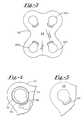
- FIG. 1is a schematic view of an anterior cervical plate and fixation system secured to two vertebrae in accordance with the present invention
- FIG. 2is a top view of the cervical plate
- FIG. 3is a bottom view of the cervical plate
- FIGS. 4 and 5are enlarged partial top and bottom views, respectively;
- FIG. 6is a sectional view taken along the line 6 — 6 in FIG. 1;
- FIG. 7is a sectional view taken along the line 7 — 7 in FIG. 1;
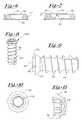
- FIG. 8is an isometric view of one of the system fasteners
- FIG. 9is a side view of the fastener
- FIG. 10is a top view of the fastener
- FIG. 11is a sectional view taken along the line 11 — 11 in FIG. 10;
- FIG. 12is a side view of a drive tool used to install the fasteners
- FIG. 13is an isometric view of one end of the drive tool
- FIG. 14is a side sectional view of a drive tool sleeve
- FIG. 15is a side view of a locking tool shaft used to close the retaining feature
- FIG. 16is an end view of the locking tool shaft
- FIG. 17is a side view of a releasing tool shaft used to open the retaining feature
- FIG. 18is an end view of the releasing tool shaft
- FIG. 19is a top view similar to FIG. 2, further illustrating the fastener
- FIG. 20is a sectional view taken along the line 20 — 20 in FIG. 19;
- FIG. 21is a top view similar to FIG. 19, illustrating a retaining feature in the closed position
- FIG. 22is a sectional view taken along the line 22 — 22 in FIG. 21;
- FIG. 23is a partial top view of an alternative embodiment cervical plate
- FIG. 24is a top view similar to FIG. 23, showing a retaining tab of the plate in a closed position;
- FIG. 25is a sectional view of a further alternative embodiment cervical plate
- FIG. 26is a side view of an alternative embodiment fastener used with the plate in FIG. 25;
- FIG. 27is a sectional view showing the fastener installed within the plate.
- FIGS. 28 and 29schematically illustrate alternative orientations of the fasteners with respect to the plate.
- FIG. 1a cervical plate and fixation system 16 constructed in accordance with the present invention.
- System 16is shown in connection with the upper cervical spine, secured to two vertebrae indicated at 18 and 20 .
- the systemis secured integrally to both of the vertebrae, and thus maintains the vertebrae integrally with respect to one another, in a desired orientation and at a desired spacing from one another as shown.
- System 16includes a cervical plate 22 and four threaded fasteners or bone screws 24 a - 24 d .
- Each of the fastenersextends through one of four apertures in the cervical plate, and further penetrates the osseous material (one of the vertebrae) to anchor the cervical plate.
- the preferred material for plate 22 and fasteners 24is titanium, which provides the requisite strength and resiliency for plate 22 to support the vertebrae in the manner indicated. Further, the titanium plate has sufficient ductility to permit curving the plate about a longitudinal axis (vertical in the figure) so that the cervical plate more readily conforms to the vertebrae. The ductility also plays a role in the use of retaining features that capture each fastener within its aperture, as will be explained.
- Certain stainless steelsare suitable as alternatives to titanium in the plate and fastener construction.
- FIGS. 2 and 3show cervical plate 22 apart from the fasteners, in top plan and bottom plan, respectively, and also show the plate in a flat configuration prior to its curvature to conform to the vertebrae.
- the platehas opposite anterior and posterior surfaces, indicated respectively at 26 and 28 , that are parallel to one another and substantially planar before the plate is curved.
- Four pockets or apertures indicated at 30 a - 30 dare formed through the cervical plate for receiving fasteners 24 a - 24 d used to secure the plate to the osseous material of the vertebrae.
- the plateis symmetrical about longitudinal and transverse central axes, which are respectively vertical and horizontal as viewed in FIGS. 2 and 3.
- FIG. 4illustrates aperture 30 a and the surrounding portion of cervical plate 22 in greater detail. Because apertures 30 b - 30 d are similar, only aperture 30 a is described in detail.
- the apertureis defined by an interior wall of the plate that has three sections, an outer section 32 , a spherical section 34 and an inner or posterior section 36 (FIG. 7 ). Outer section 32 is beveled at about a 45° angle relative to anterior surface 26 .
- the spherical profile of section 34conforms to a spherical profile of the associated fastener 24 a . The utility of this arrangement is discussed below.
- outer section 32is continuous about the aperture
- spherical section 34 and posterior section 36are not. More particularly, material is removed from plate 22 , preferably by a laser machining process, not only to interrupt these latter sections but also to form a depression 38 open to the anterior side of the plate and extending approximately halfway through the plate thickness, as seen from FIG. 6 . Further, a portion of the plate material between aperture 30 a , beginning at a point inwardly of the anterior surface 26 , is removed to leave a curved retaining feature 40 .
- the retaining featureresembles a beam or bridge, attached at its opposite ends to the remainder of the cervical plate.
- the preferred process for forming the retaining featureis laser cutting or laser machining, due to accuracy and the ability to control the depth of depression 38 , e.g., to about 0.5 inches in a cervical plate having a thickness of about 0.9 inches.
- FIGS. 8-11show fastener 24 a , which is substantially identical to the remaining fasteners.
- the fastenerincludes an elongate shank 42 with external threads 44 for securing the fastener within a vertebra or other bony material, thus to anchor plate 22 .
- the fasteneralso has an enlarged head 46 with a spherical profile 48 sized to allow the head to nest within spherical section 34 of the aperture.
- a projection 50with an annular curved surface 52 to facilitate a gripping of the fastener with a tool described below.
- a hexagonal recess 54is formed into the fastener head, to allow use of a tool with a hexagonal shaft to turn or drive the fastener.
- the head, projection and recessalso are seen in FIG. 11 .
- FIG. 12shows a drive tool 56 used to secure the fasteners by turning them into bony material, thus to secure the cervical plate.
- Tool 56includes an elongate shaft 58 and a handle 60 fixed to the proximal end of the shaft.
- a distal end 62 of the shafthas a profile that is non-circular, in this case hexagonal, corresponding to recess 54 of the fastener.
- a sleeve 64is removably mounted to shaft 58 near the distal end, positioned such that a portion of the shaft distal end projects beyond the sleeve.
- sleeve 64is internally threaded at 66 and is removably mounted to shaft 58 by virtue of corresponding external threads (not shown) on the shaft.
- Three flexures or sleeve segments 68project distally from the remainder of sleeve 58 , separated from one another by gaps 70 .
- At the end of each flexureis a nodule 72 , as best seen in FIG. 14 .
- the complete plate fixation systemincludes two further tools: a locking tool 74 and a releasing tool 76 , used respectively to retain a fastener within its associated aperture and release the fastener from the aperture.
- FIG. 15shows a locking tool shaft 78 .
- the shaftis knurled at its proximal end as indicated at 80 , for the later installation of a handle similar to handle 60 .
- a distal end 82 of the shaftis shaped to provide two projections 84 and 86 that are substantially circular except for a flattened region 88 .
- Release tool 76includes an elongate shaft 90 shown in FIG. 17, knurled at its proximal end 92 to accept a handle.
- a distal end 94 of the shaftsupports a cuff 96 with a circular inside wall 98 surrounding the shaft, and a slightly elongated outer wall 100 presenting an oblong profile.
- system 16 to secure vertebrae 18 and 20begins with forming (curving) and aligning cervical plate 22 to determine the proper locations for four openings to be drilled in the vertebrae to accommodate fasteners 24 a - 24 d . The openings are then drilled and tapped. Due to the spherical profiles of the apertures and the fastener heads, the axial extension of each fastener need not be perpendicular to the cervical plate, but instead can be offset by pivoting the screw about an axis transverse to the longitudinal extension of the fastener. Thus, longer fasteners can be used for a more secure mounting, with the screws extended in directions to avoid their convergence or interference with one another.
- each fastenerbecomes nested within its associated aperture while urging the cervical plate against the bony material, as seen in FIG. 19 for fastener 24 a .
- head 46 and projection 50are recessed within aperture 30 , as best seen in FIG. 20 .
- retaining feature 40is plastically deformed to move a medial region 102 radially inwardly, to a closed position in which the retaining member overlies head 46 of the fastener.
- Retaining feature 40when in the closed position, engages head 46 to prevent any substantial retraction or movement of fastener 24 in the anterior direction, substantially maintaining head 46 against section 34 of the aperture, which in turn maintains posterior surface 28 of the plate against the bony material. This overcomes any tendency in fastener 24 to work loose when the fastener and plate are subject to shock, vibration or other disturbance.
- Tool 74is used to close or lock the retaining feature.
- projections 84 and 86 of the shaftare inserted into depression 38 when retaining feature 40 is in the open position shown in FIG. 19, with a substantial portion of the shaft in a rounded sector 104 of the depression and flat region 88 facing feature 40 .
- shaft 78is rotated, bringing wider portions of the projections into contact with the retaining feature, until the force applied to the feature exceeds its elastic limit and bends the feature to the closed position shown in FIG. 21 .
- titaniumis the preferred material, providing a requisite ductility that enables retaining feature 40 to be plastically deformed as described, yet retain the degree of strength required to prevent retraction of the fastener. A slight force in the posterior direction is sufficient to retain the fastener.
- release tool 76is inserted by its distal end into aperture 30 , with cuff 96 oriented angularly so that the narrow-diameter portion is adjacent the closed retaining feature. From this position, shaft 90 is rotated, rotating the cuff to progressively present larger cuff diameters to the retaining feature. This eventually applies a force that exceeds the elastic limit of the feature, once again plastically deforming the feature to move it to the open position. This provides sufficient clearance for head 46 to pass through the aperture in the anterior direction, and also enables the insertion of drive tool 56 into the head to retract the fastener.
- FIG. 23is a partial view of an anterior cervical plate 106 formed according to an alternative embodiment of the present invention.
- Plate 106includes four apertures or pockets, one of which is shown at 108 .
- a fastener 110which can be substantially identical to fasteners 24 , is nested within pocket 108 .
- materialis removed by laser cutting or otherwise to form a tab 112 extended from the cervical plate in cantilevered fashion. In this figure, tab 112 is shown in the open position.
- Cervical plate 106is secured in much the same manner as described above for cervical plate 22 .
- a locking toolsuch as tool 74 is inserted into a depression or cut-out 114 , then rotated to bend tab 112 so that the tab overlies a portion of a fastener head 116 as seen in FIG. 24 .
- the deformationis plastic, so that the tab tends to remain in the closed position to maintain the fastener head within pocket 108 .
- features like feature 40 and tab 112can be resilient and less ductile, and normally (when not subject to external stress) in the closed position. A tool is used to elastically deform the tab or other feature to the open position, if it is necessary to retract the fastener.
- FIG. 25is a sectional view of an anterior cervical plate 118 formed according to a further alternative embodiment of the invention.
- Two transversely spaced apart pockets 120 a and 120 bare illustrated, defined by spherical interior walls 122 a and 122 b , respectively.
- the center of each sphereis inside its associated pocket or aperture, i.e., between an anterior surface 124 and the posterior surface 126 of plate 118 .
- each pocketincludes a constriction 128 near the posterior surface, and a retaining feature in the form of a locking rim 130 near the anterior surface.
- FIG. 26is a side elevation of an alternative embodiment bone screw or fastener 132 .
- the screwincludes an elongate shank 134 with exterior threads 136 for securing the screw within vertebra or other bony matter.
- the screwfurther has an enlarged head 138 with a spherical profile, as indicated at 140 .
- FIG. 27shows fastener 132 with head 138 secured within pocket 120 a .
- Fastener 132like fasteners 24 and 110 , incorporates a hexagonal or other non-circular recess for use with a similarly profiled drive tool.
- six slots 142are formed in a peripheral wall 144 of head 138 , to divide the peripheral wall into six arcuit wall segments 146 . These slots, each open to the anterior end of the fastener, extend in the posterior direction beyond a transverse plane corresponding to the sphere diameter, i.e., the maximum diameter of head 138 .
- Bone screw or fastener 132is shown with its longitudinal extension substantially perpendicular to cervical plate 118 . However, it is readily apparent that the head can be pivoted about any number of transverse axes (transverse with respect to the longitudinal screw extension) so that the fastener can assume a variety of non-perpendicular orientations relative to the plate. As a result, adjacent fasteners 132 can be oriented in a diverging fashion, parallel as shown in FIG. 28, a converging but off-set fashion as in FIG. 29, or in a variety of other orientations, given the degrees of freedom for movement of each fastener head within its associated pocket. In this manner, the fastener orientations can be selected to improve or maximize holding strength, or to minimize the difficulty of drilling and tapping the bone screw holes and later installing the bone screws. All embodiments can incorporate this feature.
- structural memberssuch as cervical plates are secured to vertebrae and other bony material in a manner that substantially prevents the fasteners from working loose when subject to vibration.
- Retaining features, provided near each pocket or aperture that receives a fastener,are moveable between open and closed positions, either by elastic or plastic deformation.
- a further improvementresides in the ability to orient fasteners at a variety of non-perpendicular angles with respect to the cervical plate, which allows a relatively close spacing of fasteners without the risk of fasteners interfering with one another.
Landscapes
- Health & Medical Sciences (AREA)
- Orthopedic Medicine & Surgery (AREA)
- Surgery (AREA)
- Life Sciences & Earth Sciences (AREA)
- Heart & Thoracic Surgery (AREA)
- Nuclear Medicine, Radiotherapy & Molecular Imaging (AREA)
- Engineering & Computer Science (AREA)
- Biomedical Technology (AREA)
- Neurology (AREA)
- Medical Informatics (AREA)
- Molecular Biology (AREA)
- Animal Behavior & Ethology (AREA)
- General Health & Medical Sciences (AREA)
- Public Health (AREA)
- Veterinary Medicine (AREA)
- Surgical Instruments (AREA)
- Prostheses (AREA)
Abstract
Description
Claims (33)
Priority Applications (1)
| Application Number | Priority Date | Filing Date | Title |
|---|---|---|---|
| US09/803,394US6626907B2 (en) | 1998-05-19 | 2001-03-09 | Anterior cervical plate and fixation system |
Applications Claiming Priority (4)
| Application Number | Priority Date | Filing Date | Title |
|---|---|---|---|
| US8596298P | 1998-05-19 | 1998-05-19 | |
| US10597698P | 1998-10-28 | 1998-10-28 | |
| US09/314,617US6258089B1 (en) | 1998-05-19 | 1999-05-19 | Anterior cervical plate and fixation system |
| US09/803,394US6626907B2 (en) | 1998-05-19 | 2001-03-09 | Anterior cervical plate and fixation system |
Related Parent Applications (1)
| Application Number | Title | Priority Date | Filing Date |
|---|---|---|---|
| US09/314,617DivisionUS6258089B1 (en) | 1998-05-19 | 1999-05-19 | Anterior cervical plate and fixation system |
Publications (2)
| Publication Number | Publication Date |
|---|---|
| US20010041894A1 US20010041894A1 (en) | 2001-11-15 |
| US6626907B2true US6626907B2 (en) | 2003-09-30 |
Family
ID=26803170
Family Applications (2)
| Application Number | Title | Priority Date | Filing Date |
|---|---|---|---|
| US09/314,617Expired - LifetimeUS6258089B1 (en) | 1998-05-19 | 1999-05-19 | Anterior cervical plate and fixation system |
| US09/803,394Expired - LifetimeUS6626907B2 (en) | 1998-05-19 | 2001-03-09 | Anterior cervical plate and fixation system |
Family Applications Before (1)
| Application Number | Title | Priority Date | Filing Date |
|---|---|---|---|
| US09/314,617Expired - LifetimeUS6258089B1 (en) | 1998-05-19 | 1999-05-19 | Anterior cervical plate and fixation system |
Country Status (5)
| Country | Link |
|---|---|
| US (2) | US6258089B1 (en) |
| EP (1) | EP1124493A4 (en) |
| JP (1) | JP2002528162A (en) |
| CA (1) | CA2349544A1 (en) |
| WO (1) | WO2000024325A1 (en) |
Cited By (211)
| Publication number | Priority date | Publication date | Assignee | Title |
|---|---|---|---|---|
| US20030149434A1 (en)* | 2000-11-28 | 2003-08-07 | Paul Kamaljit S. | Bone support assembly |
| US20040127899A1 (en)* | 2002-12-31 | 2004-07-01 | Konieczynski David D. | Bone plate and screw system allowing bi-directional attachment |
| US20040127904A1 (en)* | 2002-12-31 | 2004-07-01 | Konieczynski David D. | Bone plate and resilient screw system allowing bi-directional assembly |
| US20050027296A1 (en)* | 2002-06-24 | 2005-02-03 | Jeffrey Thramann | Cervical plate with backout protection |
| US20050071006A1 (en)* | 2003-09-30 | 2005-03-31 | Kirschman David Louis | Spinal fusion system and method for fusing spinal bones |
| US20050177163A1 (en)* | 2003-12-29 | 2005-08-11 | Abdou M. S. | Plating system for bone fixation and method of implantation |
| US20050216011A1 (en)* | 2000-11-28 | 2005-09-29 | Paul Kamaljit S | Bone support plate assembly |
| US20050261781A1 (en)* | 2004-04-15 | 2005-11-24 | Sennett Andrew R | Cement-directing orthopedic implants |
| US20050283152A1 (en)* | 2004-06-17 | 2005-12-22 | Lindemann Gary S | Method and apparatus for retaining screws in a plate |
| US20050288669A1 (en)* | 2004-06-14 | 2005-12-29 | Abdou M S | Occipito fixation system and method of use |
| US20060030850A1 (en)* | 2004-07-23 | 2006-02-09 | Keegan Thomas E | Methods and apparatuses for percutaneous implant delivery |
| US20060229620A1 (en)* | 2005-03-03 | 2006-10-12 | Accin Corporation | Method and apparatus for providing a retainer for a bone stabilization device |
| US20060241611A1 (en)* | 2005-04-12 | 2006-10-26 | Frank Castro | Modular spinal implant system to assist with cervical stabilization |
| US20060271052A1 (en)* | 2005-05-12 | 2006-11-30 | Stern Joseph D | Revisable anterior cervical plating system |
| US20060293669A1 (en)* | 2005-06-10 | 2006-12-28 | Sdgi Holdings, Inc. | System and method for retaining screws relative to a vertebral plate |
| US20060293668A1 (en)* | 2005-06-10 | 2006-12-28 | Sdgi Holdings, Inc. | Bone screw locking mechanism and method of use |
| US20070016206A1 (en)* | 2002-06-24 | 2007-01-18 | Lanx, Llc | Cervical plate |
| US7204837B2 (en) | 2001-12-14 | 2007-04-17 | Paul Kamaljit S | Spinal plate assembly |
| US20070123884A1 (en)* | 2005-11-09 | 2007-05-31 | Abdou M S | Bone fixation systems and methods of implantation |
| US20070123885A1 (en)* | 2003-09-30 | 2007-05-31 | X-Spine Systems, Inc. | Screw locking mechanism and method |
| US7255699B2 (en) | 2001-12-14 | 2007-08-14 | Paul Kamaljit S | Spinal plate assembly |
| US20070225718A1 (en)* | 2006-03-22 | 2007-09-27 | Ensign Michael D | Rotolock cervical plate locking mechanism |
| US20070233078A1 (en)* | 2006-01-27 | 2007-10-04 | Justis Jeff R | Pivoting joints for spinal implants including designed resistance to motion and methods of use |
| US20070270880A1 (en)* | 2006-04-28 | 2007-11-22 | Lindemann Gary S | Bone screw revision tools and methods of use |
| US7306605B2 (en) | 2003-10-02 | 2007-12-11 | Zimmer Spine, Inc. | Anterior cervical plate |
| US20070293862A1 (en)* | 2005-09-30 | 2007-12-20 | Jackson Roger P | Dynamic stabilization connecting member with elastic core and outer sleeve |
| US20080009870A1 (en)* | 2002-10-28 | 2008-01-10 | Alan Lombardo | Bone plate assembly provided with screw locking mechanisms |
| US7341591B2 (en)* | 2003-01-30 | 2008-03-11 | Depuy Spine, Inc. | Anterior buttress staple |
| US20080140136A1 (en)* | 2003-06-18 | 2008-06-12 | Jackson Roger P | Polyaxial bone screw with cam capture |
| US20090018588A1 (en)* | 2006-12-19 | 2009-01-15 | Stephan Eckhof | Orthopedic screw fastener system |
| US20090088849A1 (en)* | 2007-09-27 | 2009-04-02 | Warsaw Orthopedic, Inc. | Intervertebral Implant |
| US20090234393A1 (en)* | 2006-04-27 | 2009-09-17 | Medicrea Technologies | Osteosynthesis plate |
| USD603508S1 (en) | 2008-07-03 | 2009-11-03 | Theken Spine, Llc | Cervical plate |
| USD603507S1 (en) | 2008-07-03 | 2009-11-03 | Theken Spine, Llc | Cervical plate |
| USD603504S1 (en) | 2008-07-03 | 2009-11-03 | Theken Spine, Llc | Cervical plate |
| USD603509S1 (en) | 2008-07-03 | 2009-11-03 | Theken Spine, Llc | Cervical plate |
| USD603505S1 (en) | 2008-07-03 | 2009-11-03 | Theken Spine, Llc | Cervical plate |
| USD603506S1 (en) | 2008-07-03 | 2009-11-03 | Theken Spine, Llc | Cervical plate |
| USD603510S1 (en) | 2008-07-03 | 2009-11-03 | Theken Spine, Llc | Cervical plate |
| USD603511S1 (en) | 2008-07-03 | 2009-11-03 | Theken Spine, Llc | Cervical plate |
| USD603503S1 (en) | 2008-07-03 | 2009-11-03 | Theken Spine, Llc | Cervical plate |
| USD603964S1 (en) | 2008-07-03 | 2009-11-10 | Theken Spine, Llc | Cervical plate |
| USD603963S1 (en) | 2008-07-03 | 2009-11-10 | Theken Spine, Llc | Cervical plate |
| USD603961S1 (en) | 2008-07-03 | 2009-11-10 | Theken Spine, Llc | Cervical plate |
| USD603962S1 (en) | 2008-07-03 | 2009-11-10 | Theken Spine, Llc | Cervical plate |
| US20090326580A1 (en)* | 2008-06-25 | 2009-12-31 | Anderson Mark E | Spinal fixation device |
| US7641701B2 (en) | 2003-09-30 | 2010-01-05 | X-Spine Systems, Inc. | Spinal fusion system and method for fusing spinal bones |
| US7662175B2 (en) | 2003-06-18 | 2010-02-16 | Jackson Roger P | Upload shank swivel head bone screw spinal implant |
| US20100121383A1 (en)* | 2008-11-10 | 2010-05-13 | Todd Stanaford | Method, system, and apparatus for mammalian bony segment stabilization |
| US7722652B2 (en) | 2006-01-27 | 2010-05-25 | Warsaw Orthopedic, Inc. | Pivoting joints for spinal implants including designed resistance to motion and methods of use |
| US20100145338A1 (en)* | 2001-05-28 | 2010-06-10 | Alfred Niederberger | Bone Plate |
| US7736380B2 (en) | 2004-12-21 | 2010-06-15 | Rhausler, Inc. | Cervical plate system |
| US7740649B2 (en) | 2004-02-26 | 2010-06-22 | Pioneer Surgical Technology, Inc. | Bone plate system and methods |
| US7766915B2 (en) | 2004-02-27 | 2010-08-03 | Jackson Roger P | Dynamic fixation assemblies with inner core and outer coil-like member |
| US7766911B1 (en) | 2002-07-05 | 2010-08-03 | Theken Spine, Llc | Fixed and variable locking fixation assembly |
| US20100228299A1 (en)* | 2009-02-23 | 2010-09-09 | Zrinski Ag | Implant for fusion of bones and/or bone parts |
| US20100234897A1 (en)* | 2009-03-13 | 2010-09-16 | Lanx, Inc. | Spinal plate assemblies with backout protection cap and methods |
| US20100241174A1 (en)* | 2007-10-16 | 2010-09-23 | Robinson James C | Bone screw retaining and removal system |
| US20100256686A1 (en)* | 2009-04-06 | 2010-10-07 | Lanx, Inc. | Bone plate assemblies with backout protection and visual indicator |
| US7875065B2 (en) | 2004-11-23 | 2011-01-25 | Jackson Roger P | Polyaxial bone screw with multi-part shank retainer and pressure insert |
| US20110022097A1 (en)* | 2009-07-24 | 2011-01-27 | Spinal USA LLC | Bone plate screw-blocking systems and methods |
| US20110022096A1 (en)* | 2009-07-24 | 2011-01-27 | Spinal USA LLC | Bone plate system and methods of using the same |
| US20110046681A1 (en)* | 2008-10-02 | 2011-02-24 | Bernard Prandi | Orthopedic implant in the form of a plate to be fixed between two bone parts |
| US20110054542A1 (en)* | 2009-08-31 | 2011-03-03 | Warsaw Orthopedic, Inc. | System with integral locking mechanism |
| US7901437B2 (en) | 2007-01-26 | 2011-03-08 | Jackson Roger P | Dynamic stabilization member with molded connection |
| US7909873B2 (en) | 2006-12-15 | 2011-03-22 | Soteira, Inc. | Delivery apparatus and methods for vertebrostenting |
| US7914561B2 (en) | 2002-12-31 | 2011-03-29 | Depuy Spine, Inc. | Resilient bone plate and screw system allowing bi-directional assembly |
| US20110106157A1 (en)* | 2009-10-30 | 2011-05-05 | Warsaw Orthropedic, Inc. | Self-Locking Interference Bone Screw for use with Spinal Implant |
| US7942909B2 (en) | 2009-08-13 | 2011-05-17 | Ortho Innovations, Llc | Thread-thru polyaxial pedicle screw system |
| US7942911B2 (en) | 2007-05-16 | 2011-05-17 | Ortho Innovations, Llc | Polyaxial bone screw |
| US7942910B2 (en) | 2007-05-16 | 2011-05-17 | Ortho Innovations, Llc | Polyaxial bone screw |
| US7947065B2 (en) | 2008-11-14 | 2011-05-24 | Ortho Innovations, Llc | Locking polyaxial ball and socket fastener |
| US7951173B2 (en) | 2007-05-16 | 2011-05-31 | Ortho Innovations, Llc | Pedicle screw implant system |
| US7951170B2 (en) | 2007-05-31 | 2011-05-31 | Jackson Roger P | Dynamic stabilization connecting member with pre-tensioned solid core |
| US7963982B2 (en) | 2007-07-16 | 2011-06-21 | X-Spine Systems, Inc. | Implant plate screw locking system and screw having a locking member |
| US7967850B2 (en) | 2003-06-18 | 2011-06-28 | Jackson Roger P | Polyaxial bone anchor with helical capture connection, insert and dual locking assembly |
| US8012177B2 (en) | 2007-02-12 | 2011-09-06 | Jackson Roger P | Dynamic stabilization assembly with frusto-conical connection |
| US8057519B2 (en) | 2006-01-27 | 2011-11-15 | Warsaw Orthopedic, Inc. | Multi-axial screw assembly |
| US8066739B2 (en) | 2004-02-27 | 2011-11-29 | Jackson Roger P | Tool system for dynamic spinal implants |
| US8070749B2 (en) | 2005-05-12 | 2011-12-06 | Stern Joseph D | Revisable anterior cervical plating system |
| US8075603B2 (en) | 2008-11-14 | 2011-12-13 | Ortho Innovations, Llc | Locking polyaxial ball and socket fastener |
| US8092502B2 (en) | 2003-04-09 | 2012-01-10 | Jackson Roger P | Polyaxial bone screw with uploaded threaded shank and method of assembly and use |
| US8092500B2 (en) | 2007-05-01 | 2012-01-10 | Jackson Roger P | Dynamic stabilization connecting member with floating core, compression spacer and over-mold |
| US8100915B2 (en) | 2004-02-27 | 2012-01-24 | Jackson Roger P | Orthopedic implant rod reduction tool set and method |
| US8100955B2 (en) | 2005-03-17 | 2012-01-24 | Spinal Elements, Inc. | Orthopedic expansion fastener |
| US8105368B2 (en) | 2005-09-30 | 2012-01-31 | Jackson Roger P | Dynamic stabilization connecting member with slitted core and outer sleeve |
| US8128667B2 (en) | 2002-09-06 | 2012-03-06 | Jackson Roger P | Anti-splay medical implant closure with multi-surface removal aperture |
| US8137386B2 (en) | 2003-08-28 | 2012-03-20 | Jackson Roger P | Polyaxial bone screw apparatus |
| US8152810B2 (en) | 2004-11-23 | 2012-04-10 | Jackson Roger P | Spinal fixation tool set and method |
| US8172885B2 (en) | 2003-02-05 | 2012-05-08 | Pioneer Surgical Technology, Inc. | Bone plate system |
| US8197518B2 (en) | 2007-05-16 | 2012-06-12 | Ortho Innovations, Llc | Thread-thru polyaxial pedicle screw system |
| US8257402B2 (en) | 2002-09-06 | 2012-09-04 | Jackson Roger P | Closure for rod receiving orthopedic implant having left handed thread removal |
| US8262710B2 (en) | 2006-10-24 | 2012-09-11 | Aesculap Implant Systems, Llc | Dynamic stabilization device for anterior lower lumbar vertebral fusion |
| US8273109B2 (en) | 2002-09-06 | 2012-09-25 | Jackson Roger P | Helical wound mechanically interlocking mating guide and advancement structure |
| US8308782B2 (en) | 2004-11-23 | 2012-11-13 | Jackson Roger P | Bone anchors with longitudinal connecting member engaging inserts and closures for fixation and optional angulation |
| US8308776B2 (en) | 2005-02-18 | 2012-11-13 | Samy Abdou | Devices and methods for dynamic fixation of skeletal structure |
| US20130006313A1 (en)* | 2004-04-19 | 2013-01-03 | Binder Lawrence J | Bone Fixation Plate |
| US8353932B2 (en) | 2005-09-30 | 2013-01-15 | Jackson Roger P | Polyaxial bone anchor assembly with one-piece closure, pressure insert and plastic elongate member |
| US8361126B2 (en) | 2007-07-03 | 2013-01-29 | Pioneer Surgical Technology, Inc. | Bone plate system |
| US8366745B2 (en) | 2007-05-01 | 2013-02-05 | Jackson Roger P | Dynamic stabilization assembly having pre-compressed spacers with differential displacements |
| US8366753B2 (en) | 2003-06-18 | 2013-02-05 | Jackson Roger P | Polyaxial bone screw assembly with fixed retaining structure |
| US8372152B2 (en) | 2003-09-30 | 2013-02-12 | X-Spine Systems, Inc. | Spinal fusion system utilizing an implant plate having at least one integral lock and ratchet lock |
| US8377100B2 (en) | 2000-12-08 | 2013-02-19 | Roger P. Jackson | Closure for open-headed medical implant |
| US8377139B2 (en) | 2010-06-17 | 2013-02-19 | Aesculap Implant Systems, Llc | Standalone interbody fusion device with locking and release mechanism |
| US8377102B2 (en) | 2003-06-18 | 2013-02-19 | Roger P. Jackson | Polyaxial bone anchor with spline capture connection and lower pressure insert |
| US8398682B2 (en) | 2003-06-18 | 2013-03-19 | Roger P. Jackson | Polyaxial bone screw assembly |
| US8444681B2 (en) | 2009-06-15 | 2013-05-21 | Roger P. Jackson | Polyaxial bone anchor with pop-on shank, friction fit retainer and winged insert |
| US8475498B2 (en) | 2007-01-18 | 2013-07-02 | Roger P. Jackson | Dynamic stabilization connecting member with cord connection |
| US8545538B2 (en) | 2005-12-19 | 2013-10-01 | M. Samy Abdou | Devices and methods for inter-vertebral orthopedic device placement |
| US8556938B2 (en) | 2009-06-15 | 2013-10-15 | Roger P. Jackson | Polyaxial bone anchor with non-pivotable retainer and pop-on shank, some with friction fit |
| US8562656B2 (en) | 2010-10-15 | 2013-10-22 | Warsaw Orrthopedic, Inc. | Retaining mechanism |
| US8574270B2 (en) | 2009-03-13 | 2013-11-05 | Spinal Simplicity Llc | Bone plate assembly with bone screw retention features |
| US8591515B2 (en) | 2004-11-23 | 2013-11-26 | Roger P. Jackson | Spinal fixation tool set and method |
| US8613761B2 (en) | 2007-09-28 | 2013-12-24 | Warsaw Orthopedic, Inc. | Surgical implant with an anti-backout feature |
| US8623019B2 (en) | 2007-07-03 | 2014-01-07 | Pioneer Surgical Technology, Inc. | Bone plate system |
| US8668723B2 (en) | 2011-07-19 | 2014-03-11 | Neurostructures, Inc. | Anterior cervical plate |
| US8740983B1 (en) | 2009-11-11 | 2014-06-03 | Nuvasive, Inc. | Spinal fusion implants and related methods |
| US8753396B1 (en) | 2010-09-13 | 2014-06-17 | Theken Spine, Llc | Intervertebral implant having back-out prevention feature |
| US8771324B2 (en) | 2011-05-27 | 2014-07-08 | Globus Medical, Inc. | Securing fasteners |
| US8784027B2 (en) | 2010-09-14 | 2014-07-22 | Enduralock, Llc | Ratchet locking mechanism for threaded fastener |
| US8814911B2 (en) | 2003-06-18 | 2014-08-26 | Roger P. Jackson | Polyaxial bone screw with cam connection and lock and release insert |
| US8814912B2 (en) | 2012-07-27 | 2014-08-26 | Zimmer Spine, Inc. | Bone stabilization member with bone screw retention mechanism |
| US8814913B2 (en) | 2002-09-06 | 2014-08-26 | Roger P Jackson | Helical guide and advancement flange with break-off extensions |
| US8814915B2 (en) | 2009-03-13 | 2014-08-26 | Spinal Simplicity Llc | Dynamic vertebral column plate system |
| US8821553B2 (en) | 2003-09-30 | 2014-09-02 | X-Spine Systems, Inc. | Spinal fusion system utilizing an implant plate having at least one integral lock |
| US8821554B2 (en) | 2008-11-10 | 2014-09-02 | Amendia, Inc. | Method, system, and apparatus for mammalian bony segment stabilization |
| US8840668B1 (en) | 2009-11-11 | 2014-09-23 | Nuvasive, Inc. | Spinal implants, instruments and related methods |
| US8845649B2 (en) | 2004-09-24 | 2014-09-30 | Roger P. Jackson | Spinal fixation tool set and method for rod reduction and fastener insertion |
| US8876868B2 (en) | 2002-09-06 | 2014-11-04 | Roger P. Jackson | Helical guide and advancement flange with radially loaded lip |
| US8900277B2 (en) | 2004-02-26 | 2014-12-02 | Pioneer Surgical Technology, Inc. | Bone plate system |
| US8911479B2 (en) | 2012-01-10 | 2014-12-16 | Roger P. Jackson | Multi-start closures for open implants |
| US8911477B2 (en) | 2007-10-23 | 2014-12-16 | Roger P. Jackson | Dynamic stabilization member with end plate support and cable core extension |
| US8936623B2 (en) | 2003-06-18 | 2015-01-20 | Roger P. Jackson | Polyaxial bone screw assembly |
| US8974504B2 (en) | 2012-05-10 | 2015-03-10 | Spinal Simplicity Llc | Dynamic bone fracture plates |
| US8979904B2 (en) | 2007-05-01 | 2015-03-17 | Roger P Jackson | Connecting member with tensioned cord, low profile rigid sleeve and spacer with torsion control |
| US8998959B2 (en) | 2009-06-15 | 2015-04-07 | Roger P Jackson | Polyaxial bone anchors with pop-on shank, fully constrained friction fit retainer and lock and release insert |
| US9050139B2 (en) | 2004-02-27 | 2015-06-09 | Roger P. Jackson | Orthopedic implant rod reduction tool set and method |
| US9078706B2 (en) | 2003-09-30 | 2015-07-14 | X-Spine Systems, Inc. | Intervertebral fusion device utilizing multiple mobile uniaxial and bidirectional screw interface plates |
| USD734853S1 (en) | 2009-10-14 | 2015-07-21 | Nuvasive, Inc. | Bone plate |
| US9095444B2 (en) | 2009-07-24 | 2015-08-04 | Warsaw Orthopedic, Inc. | Implant with an interference fit fastener |
| US9168069B2 (en) | 2009-06-15 | 2015-10-27 | Roger P. Jackson | Polyaxial bone anchor with pop-on shank and winged insert with lower skirt for engaging a friction fit retainer |
| US9186189B2 (en) | 2000-06-26 | 2015-11-17 | Stryker Spine | Bone screw retaining system |
| US9192397B2 (en) | 2006-12-15 | 2015-11-24 | Gmedelaware 2 Llc | Devices and methods for fracture reduction |
| US9198769B2 (en) | 2011-12-23 | 2015-12-01 | Pioneer Surgical Technology, Inc. | Bone anchor assembly, bone plate system, and method |
| US9198695B2 (en) | 2010-08-30 | 2015-12-01 | Zimmer Spine, Inc. | Polyaxial pedicle screw |
| USD745159S1 (en) | 2013-10-10 | 2015-12-08 | Nuvasive, Inc. | Intervertebral implant |
| US9216041B2 (en) | 2009-06-15 | 2015-12-22 | Roger P. Jackson | Spinal connecting members with tensioned cords and rigid sleeves for engaging compression inserts |
| US9216039B2 (en) | 2004-02-27 | 2015-12-22 | Roger P. Jackson | Dynamic spinal stabilization assemblies, tool set and method |
| US9220547B2 (en) | 2009-03-27 | 2015-12-29 | Spinal Elements, Inc. | Flanged interbody fusion device |
| US9375237B2 (en) | 2009-03-16 | 2016-06-28 | DePuy Synthes Products, Inc. | System and method for stabilizing vertebrae in spine surgery through a lateral access channel |
| US9408715B2 (en) | 2009-04-15 | 2016-08-09 | DePuy Synthes Products, Inc. | Arcuate fixation member |
| US9414863B2 (en) | 2005-02-22 | 2016-08-16 | Roger P. Jackson | Polyaxial bone screw with spherical capture, compression insert and alignment and retention structures |
| US9445913B2 (en) | 2009-04-15 | 2016-09-20 | DePuy Synthes Products, Inc. | Arcuate fixation member |
| US9451989B2 (en) | 2007-01-18 | 2016-09-27 | Roger P Jackson | Dynamic stabilization members with elastic and inelastic sections |
| US9453526B2 (en) | 2013-04-30 | 2016-09-27 | Degen Medical, Inc. | Bottom-loading anchor assembly |
| US9480485B2 (en) | 2006-12-15 | 2016-11-01 | Globus Medical, Inc. | Devices and methods for vertebrostenting |
| US9480517B2 (en) | 2009-06-15 | 2016-11-01 | Roger P. Jackson | Polyaxial bone anchor with pop-on shank, shank, friction fit retainer, winged insert and low profile edge lock |
| US9486250B2 (en) | 2014-02-20 | 2016-11-08 | Mastros Innovations, LLC. | Lateral plate |
| US9615866B1 (en) | 2004-10-18 | 2017-04-11 | Nuvasive, Inc. | Surgical fixation system and related methods |
| US9629664B2 (en) | 2014-01-20 | 2017-04-25 | Neurostructures, Inc. | Anterior cervical plate |
| US9657766B2 (en) | 2010-09-14 | 2017-05-23 | Enduralock, Llc | Tools and ratchet locking mechanisms for threaded fasteners |
| US9743957B2 (en) | 2004-11-10 | 2017-08-29 | Roger P. Jackson | Polyaxial bone screw with shank articulation pressure insert and method |
| US9841046B2 (en) | 2015-04-17 | 2017-12-12 | Enduralock, Llc | Locking fastener with deflectable lock |
| US9877756B2 (en) | 2011-01-20 | 2018-01-30 | Alphatec Spine, Inc. | Bone fixation methods |
| US9907574B2 (en) | 2008-08-01 | 2018-03-06 | Roger P. Jackson | Polyaxial bone anchors with pop-on shank, friction fit fully restrained retainer, insert and tool receiving features |
| US9943341B2 (en) | 2013-07-16 | 2018-04-17 | K2M, Llc | Retention plate member for a spinal plate system |
| US9980753B2 (en) | 2009-06-15 | 2018-05-29 | Roger P Jackson | pivotal anchor with snap-in-place insert having rotation blocking extensions |
| US9987052B2 (en) | 2015-02-24 | 2018-06-05 | X-Spine Systems, Inc. | Modular interspinous fixation system with threaded component |
| US10039578B2 (en) | 2003-12-16 | 2018-08-07 | DePuy Synthes Products, Inc. | Methods and devices for minimally invasive spinal fixation element placement |
| US10039648B2 (en) | 2015-05-06 | 2018-08-07 | Choice Spine, Lp | Intervertebral implant device |
| US10125807B2 (en) | 2015-09-08 | 2018-11-13 | Enduralock, Llc | Locking mechanisms with deflectable washer members |
| US10194951B2 (en) | 2005-05-10 | 2019-02-05 | Roger P. Jackson | Polyaxial bone anchor with compound articulation and pop-on shank |
| US10206722B2 (en) | 2008-04-25 | 2019-02-19 | Pioneer Surgical Technology, Inc. | Bone plate system |
| US10213237B2 (en) | 2014-10-03 | 2019-02-26 | Stryker European Holdings I, Llc | Periprosthetic extension plate |
| US10215217B2 (en) | 2015-04-17 | 2019-02-26 | Enduralock, Llc | Locking fastener with deflectable lock |
| US10251685B2 (en) | 2016-03-17 | 2019-04-09 | Stryker European Holdings I, Llc | Floating locking insert |
| US10258387B2 (en) | 2006-06-30 | 2019-04-16 | Alphatec Spine, Inc. | Fastener retention system for spinal plates |
| US10258382B2 (en) | 2007-01-18 | 2019-04-16 | Roger P. Jackson | Rod-cord dynamic connection assemblies with slidable bone anchor attachment members along the cord |
| US10299839B2 (en) | 2003-12-16 | 2019-05-28 | Medos International Sárl | Percutaneous access devices and bone anchor assemblies |
| US10363070B2 (en) | 2009-06-15 | 2019-07-30 | Roger P. Jackson | Pivotal bone anchor assemblies with pressure inserts and snap on articulating retainers |
| US10383660B2 (en) | 2007-05-01 | 2019-08-20 | Roger P. Jackson | Soft stabilization assemblies with pretensioned cords |
| USD858769S1 (en) | 2014-11-20 | 2019-09-03 | Nuvasive, Inc. | Intervertebral implant |
| US10512547B2 (en) | 2017-05-04 | 2019-12-24 | Neurostructures, Inc. | Interbody spacer |
| US10543107B2 (en) | 2009-12-07 | 2020-01-28 | Samy Abdou | Devices and methods for minimally invasive spinal stabilization and instrumentation |
| US10548740B1 (en) | 2016-10-25 | 2020-02-04 | Samy Abdou | Devices and methods for vertebral bone realignment |
| US10575961B1 (en) | 2011-09-23 | 2020-03-03 | Samy Abdou | Spinal fixation devices and methods of use |
| US10695105B2 (en) | 2012-08-28 | 2020-06-30 | Samy Abdou | Spinal fixation devices and methods of use |
| US10729469B2 (en) | 2006-01-09 | 2020-08-04 | Roger P. Jackson | Flexible spinal stabilization assembly with spacer having off-axis core member |
| US10758361B2 (en) | 2015-01-27 | 2020-09-01 | Spinal Elements, Inc. | Facet joint implant |
| US10801540B2 (en) | 2015-04-17 | 2020-10-13 | Enduralock, Llc | Locking mechanisms with deflectable lock member |
| US10857003B1 (en) | 2015-10-14 | 2020-12-08 | Samy Abdou | Devices and methods for vertebral stabilization |
| US10918498B2 (en) | 2004-11-24 | 2021-02-16 | Samy Abdou | Devices and methods for inter-vertebral orthopedic device placement |
| US10973648B1 (en) | 2016-10-25 | 2021-04-13 | Samy Abdou | Devices and methods for vertebral bone realignment |
| US10980641B2 (en) | 2017-05-04 | 2021-04-20 | Neurostructures, Inc. | Interbody spacer |
| US11000321B2 (en) | 2017-05-25 | 2021-05-11 | Altus Partners Llc | Secondary screw blocking mechanism |
| US11006982B2 (en) | 2012-02-22 | 2021-05-18 | Samy Abdou | Spinous process fixation devices and methods of use |
| US11071629B2 (en) | 2018-10-13 | 2021-07-27 | Neurostructures Inc. | Interbody spacer |
| US11076892B2 (en) | 2018-08-03 | 2021-08-03 | Neurostructures, Inc. | Anterior cervical plate |
| US11111950B2 (en) | 2019-04-01 | 2021-09-07 | Enduralock, Llc | Locking mechanisms with deflectable lock member |
| US11154338B2 (en) | 2011-01-20 | 2021-10-26 | Alphatec Spine, Inc. | Bone fixation systems and methods |
| US11173040B2 (en) | 2012-10-22 | 2021-11-16 | Cogent Spine, LLC | Devices and methods for spinal stabilization and instrumentation |
| US11179248B2 (en) | 2018-10-02 | 2021-11-23 | Samy Abdou | Devices and methods for spinal implantation |
| US11304817B2 (en) | 2020-06-05 | 2022-04-19 | Neurostructures, Inc. | Expandable interbody spacer |
| US11382761B2 (en) | 2020-04-11 | 2022-07-12 | Neurostructures, Inc. | Expandable interbody spacer |
| US11382769B2 (en) | 2018-09-20 | 2022-07-12 | Spinal Elements, Inc. | Spinal implant device |
| US11419642B2 (en) | 2003-12-16 | 2022-08-23 | Medos International Sarl | Percutaneous access devices and bone anchor assemblies |
| US11717419B2 (en) | 2020-12-10 | 2023-08-08 | Neurostructures, Inc. | Expandable interbody spacer |
| US11877779B2 (en) | 2020-03-26 | 2024-01-23 | Xtant Medical Holdings, Inc. | Bone plate system |
| US11911284B2 (en) | 2020-11-19 | 2024-02-27 | Spinal Elements, Inc. | Curved expandable interbody devices and deployment tools |
| US12279969B2 (en) | 2020-12-17 | 2025-04-22 | Spinal Elements, Inc. | Spinal implant device |
| US12383311B2 (en) | 2010-05-14 | 2025-08-12 | Roger P. Jackson | Pivotal bone anchor assembly and method for use thereof |
Families Citing this family (196)
| Publication number | Priority date | Publication date | Assignee | Title |
|---|---|---|---|---|
| US20040220571A1 (en)* | 1998-04-30 | 2004-11-04 | Richard Assaker | Bone plate assembly |
| FR2778088B1 (en)* | 1998-04-30 | 2000-09-08 | Materiel Orthopedique En Abreg | ANTERIOR IMPLANT, PARTICULARLY FOR THE CERVICAL RACHIS |
| US6533786B1 (en)* | 1999-10-13 | 2003-03-18 | Sdgi Holdings, Inc. | Anterior cervical plating system |
| US6258089B1 (en)* | 1998-05-19 | 2001-07-10 | Alphatec Manufacturing, Inc. | Anterior cervical plate and fixation system |
| US6261291B1 (en) | 1999-07-08 | 2001-07-17 | David J. Talaber | Orthopedic implant assembly |
| FR2897259B1 (en) | 2006-02-15 | 2008-05-09 | Ldr Medical Soc Par Actions Si | INTERSOMATIC TRANSFORAMINAL CAGE WITH INTERBREBAL FUSION GRAFT AND CAGE IMPLANTATION INSTRUMENT |
| US6692503B2 (en)* | 1999-10-13 | 2004-02-17 | Sdgi Holdings, Inc | System and method for securing a plate to the spinal column |
| US6706046B2 (en) | 2000-02-01 | 2004-03-16 | Hand Innovations, Inc. | Intramedullary fixation device for metaphyseal long bone fractures and methods of using the same |
| US7857838B2 (en) | 2003-03-27 | 2010-12-28 | Depuy Products, Inc. | Anatomical distal radius fracture fixation plate |
| US6767351B2 (en) | 2000-02-01 | 2004-07-27 | Hand Innovations, Inc. | Fixation system with multidirectional stabilization pegs |
| US20040153073A1 (en) | 2000-02-01 | 2004-08-05 | Hand Innovations, Inc. | Orthopedic fixation system including plate element with threaded holes having divergent axes |
| US7695502B2 (en) | 2000-02-01 | 2010-04-13 | Depuy Products, Inc. | Bone stabilization system including plate having fixed-angle holes together with unidirectional locking screws and surgeon-directed locking screws |
| US20060041260A1 (en)* | 2000-02-01 | 2006-02-23 | Orbay Jorge L | Fixation system with plate having holes with divergent axes and multidirectional fixators for use therethrough |
| DE60136980D1 (en)* | 2000-03-28 | 2009-01-22 | Showa Ika Kogyo Co Ltd | Spine implant, drive tool and nut guide |
| FR2810532B1 (en)* | 2000-06-26 | 2003-05-30 | Stryker Spine Sa | BONE IMPLANT WITH ANNULAR LOCKING MEANS |
| US6730127B2 (en) | 2000-07-10 | 2004-05-04 | Gary K. Michelson | Flanged interbody spinal fusion implants |
| US7833250B2 (en) | 2004-11-10 | 2010-11-16 | Jackson Roger P | Polyaxial bone screw with helically wound capture connection |
| US6740088B1 (en) | 2000-10-25 | 2004-05-25 | Sdgi Holdings, Inc. | Anterior lumbar plate and method |
| US6656181B2 (en)* | 2000-11-22 | 2003-12-02 | Robert A Dixon | Method and device utilizing tapered screw shanks for spinal stabilization |
| US6413259B1 (en) | 2000-12-14 | 2002-07-02 | Blackstone Medical, Inc | Bone plate assembly including a screw retaining member |
| FR2823096B1 (en)* | 2001-04-06 | 2004-03-19 | Materiel Orthopedique En Abreg | PLATE FOR LTE AND LTE VERTEBRATE OSTEOSYNTHESIS DEVICE, OSTEOSYNTHESIS DEVICE INCLUDING SUCH A PLATE, AND INSTRUMENT FOR LAYING SUCH A PLATE |
| JP4234440B2 (en)* | 2001-04-06 | 2009-03-04 | ウォーソー・オーソペディック・インコーポレーテッド | Front plate mounting system and method |
| US7097645B2 (en)* | 2001-06-04 | 2006-08-29 | Sdgi Holdings, Inc. | Dynamic single-lock anterior cervical plate system having non-detachably fastened and moveable segments |
| CA2443429C (en)* | 2001-06-04 | 2010-08-10 | Gary Karlin Michelson | Anterior cervical plate system having vertebral body engaging anchors, connecting plate, and method for installation thereof |
| US7186256B2 (en)* | 2001-06-04 | 2007-03-06 | Warsaw Orthopedic, Inc. | Dynamic, modular, single-lock anterior cervical plate system having assembleable and movable segments |
| JP4283665B2 (en)* | 2001-06-04 | 2009-06-24 | ウォーソー・オーソペディック・インコーポレーテッド | Dynamic plate for anterior cervical spine with movable segments |
| US7041105B2 (en)* | 2001-06-06 | 2006-05-09 | Sdgi Holdings, Inc. | Dynamic, modular, multilock anterior cervical plate system having detachably fastened assembleable and moveable segments |
| US7044952B2 (en)* | 2001-06-06 | 2006-05-16 | Sdgi Holdings, Inc. | Dynamic multilock anterior cervical plate system having non-detachably fastened and moveable segments |
| US6679883B2 (en) | 2001-10-31 | 2004-01-20 | Ortho Development Corporation | Cervical plate for stabilizing the human spine |
| US7766947B2 (en) | 2001-10-31 | 2010-08-03 | Ortho Development Corporation | Cervical plate for stabilizing the human spine |
| US7008426B2 (en) | 2001-12-14 | 2006-03-07 | Paul Kamaljit S | Bone treatment plate assembly |
| AR038680A1 (en) | 2002-02-19 | 2005-01-26 | Synthes Ag | INTERVERTEBRAL IMPLANT |
| FR2836369B1 (en)* | 2002-02-26 | 2004-04-30 | Medicrea | OSTEOSYNTHESIS OR ARTHRODESIS MATERIAL COMPRISING A BONE PLATE AND SCREWS FOR FIXING THIS PLATE |
| US20050096657A1 (en)* | 2002-02-26 | 2005-05-05 | Alex Autericque | Osteosynthesis or arthrodesis material comprising a bony plate |
| US6695846B2 (en) | 2002-03-12 | 2004-02-24 | Spinal Innovations, Llc | Bone plate and screw retaining mechanism |
| US6989012B2 (en)* | 2002-07-16 | 2006-01-24 | Sdgi Holdings, Inc. | Plating system for stabilizing a bony segment |
| US7625378B2 (en)* | 2002-09-30 | 2009-12-01 | Warsaw Orthopedic, Inc. | Devices and methods for securing a bone plate to a bony segment |
| US7682392B2 (en) | 2002-10-30 | 2010-03-23 | Depuy Spine, Inc. | Regenerative implants for stabilizing the spine and devices for attachment of said implants |
| US7780664B2 (en)* | 2002-12-10 | 2010-08-24 | Depuy Products, Inc. | Endosteal nail |
| CA2515247C (en) | 2003-02-06 | 2010-10-05 | Synthes (U.S.A.) | Intervertebral implant |
| US7819903B2 (en) | 2003-03-31 | 2010-10-26 | Depuy Spine, Inc. | Spinal fixation plate |
| US6945973B2 (en)* | 2003-05-01 | 2005-09-20 | Nuvasive, Inc. | Slidable bone plate system |
| US7377923B2 (en) | 2003-05-22 | 2008-05-27 | Alphatec Spine, Inc. | Variable angle spinal screw assembly |
| DE10326643A1 (en)* | 2003-06-11 | 2004-12-30 | Mückter, Helmut, Dr. med. Dipl.-Ing. | Osteosynthesis plate or comparable implant with ball sleeve |
| US7309340B2 (en) | 2003-06-20 | 2007-12-18 | Medicinelodge, Inc. | Method and apparatus for bone plating |
| KR100552117B1 (en)* | 2003-07-22 | 2006-02-13 | 유앤아이 주식회사 | Cervical vertebrae device and driver used in it |
| US7909860B2 (en) | 2003-09-03 | 2011-03-22 | Synthes Usa, Llc | Bone plate with captive clips |
| US7857839B2 (en)* | 2003-09-03 | 2010-12-28 | Synthes Usa, Llc | Bone plate with captive clips |
| US20050049595A1 (en)* | 2003-09-03 | 2005-03-03 | Suh Sean S. | Track-plate carriage system |
| US8182518B2 (en)* | 2003-12-22 | 2012-05-22 | Life Spine, Inc. | Static and dynamic cervical plates and cervical plate constructs |
| US20050149021A1 (en)* | 2003-12-23 | 2005-07-07 | Tozzi James E. | Spinal implant device |
| US7678137B2 (en) | 2004-01-13 | 2010-03-16 | Life Spine, Inc. | Pedicle screw constructs for spine fixation systems |
| EP2113227B1 (en) | 2004-02-04 | 2015-07-29 | LDR Medical | Intervertebral disc prosthesis |
| CA2603992A1 (en)* | 2004-04-07 | 2005-10-20 | Cg Surgical Limited | Devices to stabilise the lamina |
| US7942913B2 (en)* | 2004-04-08 | 2011-05-17 | Ebi, Llc | Bone fixation device |
| US7938848B2 (en)* | 2004-06-09 | 2011-05-10 | Life Spine, Inc. | Spinal fixation system |
| US7744635B2 (en)* | 2004-06-09 | 2010-06-29 | Spinal Generations, Llc | Spinal fixation system |
| US20060036250A1 (en)* | 2004-08-12 | 2006-02-16 | Lange Eric C | Antero-lateral plating systems for spinal stabilization |
| US8926672B2 (en) | 2004-11-10 | 2015-01-06 | Roger P. Jackson | Splay control closure for open bone anchor |
| WO2006057837A1 (en) | 2004-11-23 | 2006-06-01 | Jackson Roger P | Spinal fixation tool attachment structure |
| US7691133B2 (en)* | 2004-11-30 | 2010-04-06 | Integra Lifesciences Corporation | Systems and methods for bone fixation |
| US8353939B2 (en)* | 2005-01-12 | 2013-01-15 | Warsaw Orthopedic, Inc. | Anchor retaining mechanisms for bone plates |
| US20060195089A1 (en)* | 2005-02-03 | 2006-08-31 | Lehuec Jean-Charles | Spinal plating and intervertebral support systems and methods |
| US7481811B2 (en)* | 2005-03-11 | 2009-01-27 | Synthes (U.S.A.) | Translational plate with spring beam retainer |
| US7678113B2 (en)* | 2005-04-19 | 2010-03-16 | Warsaw Orthopedic, Inc. | Antero-lateral plating systems and methods for spinal stabilization |
| US7452370B2 (en)* | 2005-04-29 | 2008-11-18 | Warsaw Orthopedic, Inc | Apparatus for retaining a bone anchor in a bone plate and method for use thereof |
| US7905909B2 (en) | 2005-09-19 | 2011-03-15 | Depuy Products, Inc. | Bone stabilization system including multi-directional threaded fixation element |
| FR2891135B1 (en) | 2005-09-23 | 2008-09-12 | Ldr Medical Sarl | INTERVERTEBRAL DISC PROSTHESIS |
| US7699880B2 (en)* | 2005-10-24 | 2010-04-20 | Depuy Products, Inc. | Bone fixation system and bone screws having anti-back out feature |
| AU2005338325A1 (en) | 2005-11-16 | 2007-05-24 | Synthes Gmbh | A through hole for bone fixation device |
| EP1971282A2 (en) | 2006-01-10 | 2008-09-24 | Life Spine, Inc. | Pedicle screw constructs and spinal rod attachment assemblies |
| WO2007098188A2 (en)* | 2006-02-21 | 2007-08-30 | Life Spine, Inc. | Structure for joining and retaining multi-part orthopedic implants |
| EP1988855A2 (en) | 2006-02-27 | 2008-11-12 | Synthes GmbH | Intervertebral implant with fixation geometry |
| US7806900B2 (en) | 2006-04-26 | 2010-10-05 | Illuminoss Medical, Inc. | Apparatus and methods for delivery of reinforcing materials to bone |
| US20070270859A1 (en)* | 2006-04-28 | 2007-11-22 | Sdgi Holdings, Inc. | Orthopedic screw with break away drive |
| DE102006026590B3 (en)* | 2006-05-31 | 2008-01-03 | Aesculap Ag & Co. Kg | implant |
| US8388660B1 (en) | 2006-08-01 | 2013-03-05 | Samy Abdou | Devices and methods for superior fixation of orthopedic devices onto the vertebral column |
| US8206390B2 (en)* | 2006-11-02 | 2012-06-26 | Warsaw Orthopedic, Inc. | Uni-directional ratcheting bone plate assembly |
| US7879041B2 (en) | 2006-11-10 | 2011-02-01 | Illuminoss Medical, Inc. | Systems and methods for internal bone fixation |
| CA2669129C (en) | 2006-11-10 | 2014-09-16 | Illuminoss Medical, Inc. | Systems and methods for internal bone fixation |
| WO2008077137A1 (en)* | 2006-12-19 | 2008-06-26 | Small Bone Innovations, Inc. | Locking fixation system and lag tool |
| US8425607B2 (en)* | 2007-04-03 | 2013-04-23 | Warsaw Orthopedic, Inc. | Anchor member locking features |
| FR2916956B1 (en) | 2007-06-08 | 2012-12-14 | Ldr Medical | INTERSOMATIC CAGE, INTERVERTEBRAL PROSTHESIS, ANCHORING DEVICE AND IMPLANTATION INSTRUMENTATION |
| US20090177239A1 (en)* | 2007-08-06 | 2009-07-09 | Michael Castro | Cervical plate instrument kit |
| US9427289B2 (en) | 2007-10-31 | 2016-08-30 | Illuminoss Medical, Inc. | Light source |
| EP3184065B1 (en) | 2007-11-09 | 2019-06-19 | Stryker European Holdings I, LLC | Cervical plate with a feedback device for selective association with bone screw blocking mechanism |
| JP2011502708A (en) | 2007-11-16 | 2011-01-27 | ジンテス ゲゼルシャフト ミット ベシュレンクテル ハフツング | Low profile intervertebral implant |
| FR2924015A1 (en)* | 2007-11-26 | 2009-05-29 | Spineway Soc Par Actions Simpl | Screw head holding system for e.g. osteosynthesis plate in cervical backbone, has hole and screw head presenting complementary holding shapes after placing and locking screw in support, where hole presents arrangements formed by slit |
| US8206143B2 (en) | 2007-12-13 | 2012-06-26 | Biomet Manufacturing Corp. | Modular articulating cement spacer |
| US8403968B2 (en) | 2007-12-26 | 2013-03-26 | Illuminoss Medical, Inc. | Apparatus and methods for repairing craniomaxillofacial bones using customized bone plates |
| FR2926975B1 (en)* | 2008-02-01 | 2010-03-26 | Alexandre Worcel | OSTEOSYNTHESIS DEVICE WITH RAPID FASTENING MEANS |
| US20090210008A1 (en)* | 2008-02-20 | 2009-08-20 | Life Spine, Inc. | Modular spine plate with projection and socket interface |
| US8551144B2 (en)* | 2008-04-22 | 2013-10-08 | Collab Comlo, LLC | Bone plate system configurable as static or dynamic implant |
| US8414584B2 (en) | 2008-07-09 | 2013-04-09 | Icon Orthopaedic Concepts, Llc | Ankle arthrodesis nail and outrigger assembly |
| EP2339976B1 (en) | 2008-07-09 | 2016-03-16 | Icon Orthopaedic Concepts, LLC | Ankle arthrodesis nail and outrigger assembly |
| WO2010025405A1 (en)* | 2008-08-29 | 2010-03-04 | Life Spine, Inc. | Single-sided dynamic spine plates |
| US8709083B2 (en) | 2009-06-04 | 2014-04-29 | William E. Duffield | Intervertebral fusion implant |
| US8328872B2 (en) | 2008-09-02 | 2012-12-11 | Globus Medical, Inc. | Intervertebral fusion implant |
| US8409208B2 (en) | 2008-10-04 | 2013-04-02 | M. Samy Abdou | Device and method to access the anterior column of the spine |
| CN102256570B (en) | 2008-11-07 | 2015-09-02 | 斯恩蒂斯有限公司 | Spacer and connecting plate assembly between vertebral bodies |
| US8992558B2 (en) | 2008-12-18 | 2015-03-31 | Osteomed, Llc | Lateral access system for the lumbar spine |
| US8210729B2 (en) | 2009-04-06 | 2012-07-03 | Illuminoss Medical, Inc. | Attachment system for light-conducting fibers |
| US8512338B2 (en) | 2009-04-07 | 2013-08-20 | Illuminoss Medical, Inc. | Photodynamic bone stabilization systems and methods for reinforcing bone |
| US9668771B2 (en) | 2009-06-15 | 2017-06-06 | Roger P Jackson | Soft stabilization assemblies with off-set connector |
| US11229457B2 (en) | 2009-06-15 | 2022-01-25 | Roger P. Jackson | Pivotal bone anchor assembly with insert tool deployment |
| US8834536B2 (en)* | 2009-07-16 | 2014-09-16 | Nexxt Spine, LLC | Cervical plate fixation system |
| EP2467098A4 (en) | 2009-08-19 | 2015-07-08 | Illuminoss Medical Inc | Devices and methods for bone alignment, stabilization and distraction |
| CN105326585B (en)* | 2009-09-17 | 2018-12-11 | Ldr控股公司 | Intervertebral implant with extensible bone anchoring element |
| US8535356B2 (en) | 2009-11-04 | 2013-09-17 | X-Spine Systems, Inc. | Screw implant and system and method for locking a screw in an implant plate |
| US9486263B2 (en) | 2009-11-04 | 2016-11-08 | X-Spine Systems, Inc. | Screw implant and system and method for locking a screw in an implant plate |
| WO2011080535A1 (en) | 2009-12-31 | 2011-07-07 | Lrd Medical | Anchoring device, intervertebral implant and implantation instrument |
| US9155631B2 (en) | 2010-04-08 | 2015-10-13 | Globus Medical Inc. | Intervertbral implant |
| US8858603B1 (en) | 2010-06-09 | 2014-10-14 | Choice Spine, L.P. | Cervical plate with screw retention clip |
| US8684965B2 (en) | 2010-06-21 | 2014-04-01 | Illuminoss Medical, Inc. | Photodynamic bone stabilization and drug delivery systems |
| US9241809B2 (en) | 2010-12-21 | 2016-01-26 | DePuy Synthes Products, Inc. | Intervertebral implants, systems, and methods of use |
| WO2012088238A2 (en) | 2010-12-21 | 2012-06-28 | Synthes Usa, Llc | Intervertebral implants, systems, and methods of use |
| EP2654584A1 (en) | 2010-12-22 | 2013-10-30 | Illuminoss Medical, Inc. | Systems and methods for treating conditions and diseases of the spine |
| US8940030B1 (en) | 2011-01-28 | 2015-01-27 | Nuvasive, Inc. | Spinal fixation system and related methods |
| US9017412B2 (en) | 2011-04-29 | 2015-04-28 | Life Spine, Inc. | Spinal interbody implant with bone screw retention |
| USD662205S1 (en)* | 2011-07-13 | 2012-06-19 | Shoulder Options, Inc. | Suture anchor |
| US8936644B2 (en) | 2011-07-19 | 2015-01-20 | Illuminoss Medical, Inc. | Systems and methods for joint stabilization |
| US20130023876A1 (en) | 2011-07-19 | 2013-01-24 | Illuminoss Medical, Inc. | Combination Photodynamic Devices |
| CA2841962A1 (en)* | 2011-07-19 | 2013-01-24 | Illuminoss Medical, Inc. | Devices and methods for bone restructure and stabilization |
| US8591556B2 (en) | 2011-07-19 | 2013-11-26 | Globus Medical, Inc. | Locking confirmation mechanism for a bone screw and plate assembly |
| US9539109B2 (en) | 2011-09-16 | 2017-01-10 | Globus Medical, Inc. | Low profile plate |
| US9848994B2 (en) | 2011-09-16 | 2017-12-26 | Globus Medical, Inc. | Low profile plate |
| US9237957B2 (en) | 2011-09-16 | 2016-01-19 | Globus Medical, Inc. | Low profile plate |
| US10245155B2 (en) | 2011-09-16 | 2019-04-02 | Globus Medical, Inc. | Low profile plate |
| US9149365B2 (en) | 2013-03-05 | 2015-10-06 | Globus Medical, Inc. | Low profile plate |
| US9681959B2 (en) | 2011-09-16 | 2017-06-20 | Globus Medical, Inc. | Low profile plate |
| US10881526B2 (en) | 2011-09-16 | 2021-01-05 | Globus Medical, Inc. | Low profile plate |
| US11123117B1 (en) | 2011-11-01 | 2021-09-21 | Nuvasive, Inc. | Surgical fixation system and related methods |
| US8784459B2 (en) | 2012-01-17 | 2014-07-22 | Genesys Spine | Spinal plate and locking screw devices, methods, and systems |
| FR2990845B1 (en)* | 2012-05-25 | 2015-04-24 | Spirits | VERTEBRAL IMPLANT HAVING AUTONOMOUS LOCKING AND UNLOCKING MEANS |
| US20130325071A1 (en) | 2012-05-30 | 2013-12-05 | Marcin Niemiec | Aligning Vertebral Bodies |
| US8939977B2 (en) | 2012-07-10 | 2015-01-27 | Illuminoss Medical, Inc. | Systems and methods for separating bone fixation devices from introducer |
| US9326861B2 (en) | 2012-08-03 | 2016-05-03 | Globus Medical, Inc. | Stabilizing joints |
| KR101331428B1 (en)* | 2012-08-03 | 2013-11-21 | 주식회사 솔고 바이오메디칼 | Apparatus for fixing a cervical spine following an inserting angle of screw |
| US8911478B2 (en) | 2012-11-21 | 2014-12-16 | Roger P. Jackson | Splay control closure for open bone anchor |
| US9687281B2 (en) | 2012-12-20 | 2017-06-27 | Illuminoss Medical, Inc. | Distal tip for bone fixation devices |
| US10058354B2 (en) | 2013-01-28 | 2018-08-28 | Roger P. Jackson | Pivotal bone anchor assembly with frictional shank head seating surfaces |
| US9642652B2 (en)* | 2013-02-13 | 2017-05-09 | Choice Spine, Lp | Variable angle bone plate with semi-constrained articulating screw |
| US10105239B2 (en) | 2013-02-14 | 2018-10-23 | Globus Medical, Inc. | Devices and methods for correcting vertebral misalignment |
| US9585765B2 (en) | 2013-02-14 | 2017-03-07 | Globus Medical, Inc | Devices and methods for correcting vertebral misalignment |
| US8852239B2 (en) | 2013-02-15 | 2014-10-07 | Roger P Jackson | Sagittal angle screw with integral shank and receiver |
| US10117754B2 (en) | 2013-02-25 | 2018-11-06 | Globus Medical, Inc. | Expandable intervertebral implant |
| US9103367B2 (en) | 2013-03-14 | 2015-08-11 | Imds Llc | Polyaxial locking interface |
| US10327910B2 (en) | 2013-03-14 | 2019-06-25 | X-Spine Systems, Inc. | Spinal implant and assembly |
| US9404525B2 (en) | 2013-03-14 | 2016-08-02 | Imds Llc | Polyaxial locking interface |
| US9539103B2 (en) | 2013-03-15 | 2017-01-10 | Globus Medical, Inc. | Expandable intervertebral implant |
| US9034045B2 (en) | 2013-03-15 | 2015-05-19 | Globus Medical, Inc | Expandable intervertebral implant |
| US9456906B2 (en) | 2013-03-15 | 2016-10-04 | Globus Medical, Inc. | Expandable intervertebral implant |
| US9572677B2 (en) | 2013-03-15 | 2017-02-21 | Globus Medical, Inc. | Expandable intervertebral implant |
| US9186258B2 (en) | 2013-03-15 | 2015-11-17 | Globus Medical, Inc. | Expandable intervertebral implant |
| US9149367B2 (en) | 2013-03-15 | 2015-10-06 | Globus Medical Inc | Expandable intervertebral implant |
| US9474622B2 (en) | 2013-03-15 | 2016-10-25 | Globus Medical, Inc | Expandable intervertebral implant |
| US9233009B2 (en) | 2013-03-15 | 2016-01-12 | Globus Medical, Inc. | Expandable intervertebral implant |
| FR3005569B1 (en) | 2013-05-16 | 2021-09-03 | Ldr Medical | VERTEBRAL IMPLANT, VERTEBRAL IMPLANT FIXATION DEVICE AND IMPLANTATION INSTRUMENTATION |
| KR101599603B1 (en) | 2013-08-26 | 2016-03-03 | 경북대학교 산학협력단 | Medical inserting apparatus |
| WO2015038301A1 (en) | 2013-09-13 | 2015-03-19 | X-Spine Systems, Inc. | Screw implant and system and method for locking a screw in an implant plate |
| US9566092B2 (en) | 2013-10-29 | 2017-02-14 | Roger P. Jackson | Cervical bone anchor with collet retainer and outer locking sleeve |
| US9717533B2 (en) | 2013-12-12 | 2017-08-01 | Roger P. Jackson | Bone anchor closure pivot-splay control flange form guide and advancement structure |
| US9451993B2 (en) | 2014-01-09 | 2016-09-27 | Roger P. Jackson | Bi-radial pop-on cervical bone anchor |
| US9877759B2 (en) | 2014-02-06 | 2018-01-30 | Life Spine, Inc. | Foot implant for bone fixation |
| US9889014B2 (en) | 2014-02-06 | 2018-02-13 | Life Spine, Inc. | Implant for bone fixation |
| US9055983B1 (en) | 2014-04-24 | 2015-06-16 | Amendia, Inc. | Self-locking bone screw receiver |
| FR3020756B1 (en) | 2014-05-06 | 2022-03-11 | Ldr Medical | VERTEBRAL IMPLANT, VERTEBRAL IMPLANT FIXATION DEVICE AND IMPLANT INSTRUMENTATION |
| US11160666B2 (en) | 2014-05-15 | 2021-11-02 | Globus Medical, Inc. | Laterally insertable intervertebral spinal implant |
| US9968461B2 (en) | 2014-05-15 | 2018-05-15 | Globus Medical, Inc. | Standalone interbody implants |
| US9545320B2 (en) | 2014-05-15 | 2017-01-17 | Globus Medical, Inc. | Standalone interbody implants |
| US9675465B2 (en) | 2014-05-15 | 2017-06-13 | Globus Medical, Inc. | Standalone interbody implants |
| US9486327B2 (en) | 2014-05-15 | 2016-11-08 | Globus Medical, Inc. | Standalone interbody implants |
| US9913672B2 (en) | 2014-05-28 | 2018-03-13 | Genesys Spine | Resiliant spinal plate system |
| US10064658B2 (en) | 2014-06-04 | 2018-09-04 | Roger P. Jackson | Polyaxial bone anchor with insert guides |
| US9597119B2 (en) | 2014-06-04 | 2017-03-21 | Roger P. Jackson | Polyaxial bone anchor with polymer sleeve |
| US9192483B1 (en) | 2014-06-27 | 2015-11-24 | Amendia, Inc. | Spinal fusion system |
| US9867718B2 (en) | 2014-10-22 | 2018-01-16 | DePuy Synthes Products, Inc. | Intervertebral implants, systems, and methods of use |
| KR101639887B1 (en)* | 2014-11-11 | 2016-07-14 | 경북대학교 산학협력단 | A system for fixing cervical vertebrae and a driver used for an appratus for fixing cervical vertebrae |
| KR101608949B1 (en) | 2014-11-19 | 2016-04-04 | 경북대학교 산학협력단 | A system for fixing cervical vertebrae, an appratus for fixing cervical vertebrae and a driver used for an appratus for fixing cervical vertebrae |
| US9381093B1 (en) | 2015-02-09 | 2016-07-05 | Alliance Partners, Llc | Locking device for fixation mechanism of medical implant |
| KR101670768B1 (en) | 2015-07-16 | 2016-10-31 | 경북대학교 산학협력단 | Screw anchor assembly |
| US10034768B2 (en) | 2015-09-02 | 2018-07-31 | Globus Medical, Inc. | Implantable systems, devices and related methods |
| US10874445B2 (en) | 2015-10-13 | 2020-12-29 | Kyungpook National University Industry-Academic Cooperation Foundation | Screw fixing apparatus |
| KR101712610B1 (en) | 2015-12-29 | 2017-03-06 | 경북대학교 산학협력단 | A rod connecter |
| KR101791004B1 (en) | 2016-06-08 | 2017-10-27 | 경북대학교 산학협력단 | Screw anchor assembly and a method for using the same to pedicle screw instrumentation |
| WO2018039228A1 (en) | 2016-08-23 | 2018-03-01 | Stryker European Holdings I, Llc | Instrumentation for the implantation of spinal implants |
| US11452608B2 (en) | 2017-04-05 | 2022-09-27 | Globus Medical, Inc. | Decoupled spacer and plate and method of installing the same |
| US10376385B2 (en) | 2017-04-05 | 2019-08-13 | Globus Medical, Inc. | Decoupled spacer and plate and method of installing the same |
| EP3668442A2 (en) | 2017-08-17 | 2020-06-24 | Stryker European Holdings I, LLC | Lateral access alignment guide and rigid arm |
| EP3737339B1 (en)* | 2018-01-11 | 2024-06-05 | K2M, Inc. | Implants and instruments with flexible features |
| EP3545857B1 (en) | 2018-03-30 | 2024-01-03 | Stryker European Operations Holdings LLC | Lateral access retractor and core insertion |
| US11071572B2 (en) | 2018-06-27 | 2021-07-27 | Illuminoss Medical, Inc. | Systems and methods for bone stabilization and fixation |
| US11298244B2 (en) | 2019-01-31 | 2022-04-12 | K2M, Inc. | Interbody implants and instrumentation |
| US11534307B2 (en) | 2019-09-16 | 2022-12-27 | K2M, Inc. | 3D printed cervical standalone implant |
| US11564674B2 (en) | 2019-11-27 | 2023-01-31 | K2M, Inc. | Lateral access system and method of use |
| JP7229575B1 (en)* | 2021-08-27 | 2023-02-28 | ヤマト科学株式会社 | test equipment |
Citations (45)
| Publication number | Priority date | Publication date | Assignee | Title |
|---|---|---|---|---|
| US3901298A (en)* | 1974-04-05 | 1975-08-26 | John B Eby | Fastener holding attachment |
| US4197886A (en)* | 1977-09-06 | 1980-04-15 | Clyde Corporation | Fastener driving tool and fastener holding nosepiece |
| US4484570A (en)* | 1980-05-28 | 1984-11-27 | Synthes Ltd. | Device comprising an implant and screws for fastening said implant to a bone, and a device for connecting two separated pieces of bone |
| US5129292A (en)* | 1991-02-06 | 1992-07-14 | Ocean Shore Toys | Disposable holder for starting screws |
| US5176678A (en)* | 1991-03-14 | 1993-01-05 | Tsou Paul M | Orthopaedic device with angularly adjustable anchor attachments to the vertebrae |
| US5234430A (en)* | 1991-12-18 | 1993-08-10 | Huebner Randall J | Orthopedic fixation screw and method |
| US5261910A (en)* | 1992-02-19 | 1993-11-16 | Acromed Corporation | Apparatus for maintaining spinal elements in a desired spatial relationship |
| US5330473A (en)* | 1993-03-04 | 1994-07-19 | Advanced Spine Fixation Systems, Inc. | Branch connector for spinal fixation systems |
| US5344421A (en)* | 1993-07-16 | 1994-09-06 | Amei Technologies Inc. | Apparatus and method for adjusting a bone plate |
| US5454811A (en)* | 1993-11-08 | 1995-10-03 | Smith & Nephew Dyonics, Inc. | Cam lock orthopedic fixation screw and method |
| US5486176A (en)* | 1991-03-27 | 1996-01-23 | Smith & Nephew Richards, Inc. | Angled bone fixation apparatus |
| US5488263A (en)* | 1994-02-17 | 1996-01-30 | Mitsubishi Denki Kabushiki Kaisha | Color selecting electrode for cathode-ray tube |
| US5549608A (en)* | 1995-07-13 | 1996-08-27 | Fastenetix, L.L.C. | Advanced polyaxial locking screw and coupling element device for use with rod fixation apparatus |
| US5554157A (en)* | 1995-07-13 | 1996-09-10 | Fastenetix, L.L.C. | Rod securing polyaxial locking screw and coupling element assembly |
| US5584834A (en)* | 1995-07-13 | 1996-12-17 | Fastenetix, L.L.C. | Polyaxial locking screw and coupling element assembly for use with side loading rod fixation apparatus |
| US5643265A (en)* | 1995-04-13 | 1997-07-01 | Fastenetix, L.L.C. | Dynamic compression polyaxial locking screw plate assembly |
| US5662652A (en)* | 1994-04-28 | 1997-09-02 | Schafer Micomed Gmbh | Bone surgery holding apparatus |
| US5667506A (en)* | 1992-10-22 | 1997-09-16 | Danek Medical, Inc. | Spinal rod transverse connector for supporting vertebral fixation elements |
| US5669911A (en)* | 1995-04-13 | 1997-09-23 | Fastenetix, L.L.C. | Polyaxial pedicle screw |
| US5672175A (en)* | 1993-08-27 | 1997-09-30 | Martin; Jean Raymond | Dynamic implanted spinal orthosis and operative procedure for fitting |
| US5676666A (en)* | 1994-08-23 | 1997-10-14 | Spinetech, Inc. | Cervical spine stabilization system |
| US5713900A (en)* | 1996-05-31 | 1998-02-03 | Acromed Corporation | Apparatus for retaining bone portions in a desired spatial relationship |
| US5725528A (en)* | 1997-02-12 | 1998-03-10 | Third Millennium Engineering, Llc | Modular polyaxial locking pedicle screw |
| US5733286A (en)* | 1997-02-12 | 1998-03-31 | Third Millennium Engineering, Llc | Rod securing polyaxial locking screw and coupling element assembly |
| US5733285A (en)* | 1995-07-13 | 1998-03-31 | Fastenetix, Llc | Polyaxial locking mechanism |
| US5735851A (en)* | 1996-10-09 | 1998-04-07 | Third Millennium Engineering, Llc | Modular polyaxial locking pedicle screw |
| US5776135A (en)* | 1996-12-23 | 1998-07-07 | Third Millennium Engineering, Llc | Side mounted polyaxial pedicle screw |
| US5785711A (en)* | 1997-05-15 | 1998-07-28 | Third Millennium Engineering, Llc | Polyaxial pedicle screw having a through bar clamp locking mechanism |
| US5797911A (en)* | 1996-09-24 | 1998-08-25 | Sdgi Holdings, Inc. | Multi-axial bone screw assembly |
| US5800435A (en)* | 1996-10-09 | 1998-09-01 | Techsys, Llc | Modular spinal plate for use with modular polyaxial locking pedicle screws |
| US5810819A (en)* | 1997-05-15 | 1998-09-22 | Spinal Concepts, Inc. | Polyaxial pedicle screw having a compression locking rod gripping mechanism |
| US5879350A (en)* | 1996-09-24 | 1999-03-09 | Sdgi Holdings, Inc. | Multi-axial bone screw assembly |
| US5885286A (en)* | 1996-09-24 | 1999-03-23 | Sdgi Holdings, Inc. | Multi-axial bone screw assembly |
| US5891145A (en)* | 1997-07-14 | 1999-04-06 | Sdgi Holdings, Inc. | Multi-axial screw |
| US5899901A (en)* | 1991-05-18 | 1999-05-04 | Middleton; Jeffrey Keith | Spinal fixation system |
| US5904683A (en)* | 1998-07-10 | 1999-05-18 | Sulzer Spine-Tech Inc. | Anterior cervical vertebral stabilizing device |
| US5951558A (en)* | 1998-04-22 | 1999-09-14 | Fiz; Daniel | Bone fixation device |
| US5954725A (en)* | 1996-11-07 | 1999-09-21 | Sdgi Holdings, Inc. | Multi-angle bone screw assembly using shape memory technology |
| US5964760A (en)* | 1996-10-18 | 1999-10-12 | Spinal Innovations | Spinal implant fixation assembly |
| US5976136A (en)* | 1998-05-11 | 1999-11-02 | Electro Biology, Inc. | Method and apparatus for external bone fixator |
| US6022350A (en)* | 1996-05-13 | 2000-02-08 | Stryker France S.A. | Bone fixing device, in particular for fixing to the sacrum during osteosynthesis of the backbone |
| US6139550A (en)* | 1997-02-11 | 2000-10-31 | Michelson; Gary K. | Skeletal plating system |
| US6206881B1 (en)* | 1995-09-06 | 2001-03-27 | Synthes (Usa) | Bone plate |
| US6258089B1 (en)* | 1998-05-19 | 2001-07-10 | Alphatec Manufacturing, Inc. | Anterior cervical plate and fixation system |
| US6302883B1 (en)* | 1998-10-22 | 2001-10-16 | Depuy Acromed, Inc. | Bone plate-ratcheting compression apparatus |
Family Cites Families (4)
| Publication number | Priority date | Publication date | Assignee | Title |
|---|---|---|---|---|
| FR2519857A1 (en)* | 1982-01-19 | 1983-07-22 | Butel Jean | DEVICE FOR OSTEOSYNTHESIS OF THE FRACTURES OF THE END OF THE FEMUR |
| DE69320593T2 (en)* | 1992-11-25 | 1999-03-04 | Codman & Shurtleff, Inc., Randolph, Mass. | Bone plate system |
| US5423826A (en)* | 1993-02-05 | 1995-06-13 | Danek Medical, Inc. | Anterior cervical plate holder/drill guide and method of use |
| US5498263A (en)* | 1994-06-28 | 1996-03-12 | Acromed Corporation | Transverse connector for spinal column corrective devices |
- 1999
- 1999-05-19USUS09/314,617patent/US6258089B1/ennot_activeExpired - Lifetime
- 1999-10-28CACA002349544Apatent/CA2349544A1/ennot_activeAbandoned
- 1999-10-28EPEP99958690Apatent/EP1124493A4/ennot_activeWithdrawn
- 1999-10-28WOPCT/US1999/025278patent/WO2000024325A1/ennot_activeApplication Discontinuation
- 1999-10-28JPJP2000577943Apatent/JP2002528162A/enactivePending
- 2001
- 2001-03-09USUS09/803,394patent/US6626907B2/ennot_activeExpired - Lifetime
Patent Citations (49)
| Publication number | Priority date | Publication date | Assignee | Title |
|---|---|---|---|---|
| US3901298A (en)* | 1974-04-05 | 1975-08-26 | John B Eby | Fastener holding attachment |
| US4197886A (en)* | 1977-09-06 | 1980-04-15 | Clyde Corporation | Fastener driving tool and fastener holding nosepiece |
| US4484570A (en)* | 1980-05-28 | 1984-11-27 | Synthes Ltd. | Device comprising an implant and screws for fastening said implant to a bone, and a device for connecting two separated pieces of bone |
| US5129292A (en)* | 1991-02-06 | 1992-07-14 | Ocean Shore Toys | Disposable holder for starting screws |
| US5176678A (en)* | 1991-03-14 | 1993-01-05 | Tsou Paul M | Orthopaedic device with angularly adjustable anchor attachments to the vertebrae |
| US5486176A (en)* | 1991-03-27 | 1996-01-23 | Smith & Nephew Richards, Inc. | Angled bone fixation apparatus |
| US5899901A (en)* | 1991-05-18 | 1999-05-04 | Middleton; Jeffrey Keith | Spinal fixation system |
| US5234430A (en)* | 1991-12-18 | 1993-08-10 | Huebner Randall J | Orthopedic fixation screw and method |
| US5261910A (en)* | 1992-02-19 | 1993-11-16 | Acromed Corporation | Apparatus for maintaining spinal elements in a desired spatial relationship |
| US5667506A (en)* | 1992-10-22 | 1997-09-16 | Danek Medical, Inc. | Spinal rod transverse connector for supporting vertebral fixation elements |
| US5330473A (en)* | 1993-03-04 | 1994-07-19 | Advanced Spine Fixation Systems, Inc. | Branch connector for spinal fixation systems |
| US5344421A (en)* | 1993-07-16 | 1994-09-06 | Amei Technologies Inc. | Apparatus and method for adjusting a bone plate |
| US5672175A (en)* | 1993-08-27 | 1997-09-30 | Martin; Jean Raymond | Dynamic implanted spinal orthosis and operative procedure for fitting |
| US5454811A (en)* | 1993-11-08 | 1995-10-03 | Smith & Nephew Dyonics, Inc. | Cam lock orthopedic fixation screw and method |
| US5488263A (en)* | 1994-02-17 | 1996-01-30 | Mitsubishi Denki Kabushiki Kaisha | Color selecting electrode for cathode-ray tube |
| US5662652A (en)* | 1994-04-28 | 1997-09-02 | Schafer Micomed Gmbh | Bone surgery holding apparatus |
| US5676666A (en)* | 1994-08-23 | 1997-10-14 | Spinetech, Inc. | Cervical spine stabilization system |
| US5647873A (en)* | 1995-04-13 | 1997-07-15 | Fastenetix, L.L.C. | Bicentric polyaxial locking screw and coupling element |
| US5643265A (en)* | 1995-04-13 | 1997-07-01 | Fastenetix, L.L.C. | Dynamic compression polyaxial locking screw plate assembly |
| US5669911A (en)* | 1995-04-13 | 1997-09-23 | Fastenetix, L.L.C. | Polyaxial pedicle screw |
| US5876402A (en)* | 1995-04-13 | 1999-03-02 | Errico; Joseph P. | Anterior spinal polyaxial locking screw plate assembly having recessed retaining rings |
| US5817094A (en)* | 1995-04-13 | 1998-10-06 | Fastenetix, Llc | Polyaxial locking screw and coupling element |
| US5690630A (en)* | 1995-04-13 | 1997-11-25 | Fastenetix, Llc | Polyaxial pedicle screw |
| US5733285A (en)* | 1995-07-13 | 1998-03-31 | Fastenetix, Llc | Polyaxial locking mechanism |
| US5554157A (en)* | 1995-07-13 | 1996-09-10 | Fastenetix, L.L.C. | Rod securing polyaxial locking screw and coupling element assembly |
| US5549608A (en)* | 1995-07-13 | 1996-08-27 | Fastenetix, L.L.C. | Advanced polyaxial locking screw and coupling element device for use with rod fixation apparatus |
| US5584834A (en)* | 1995-07-13 | 1996-12-17 | Fastenetix, L.L.C. | Polyaxial locking screw and coupling element assembly for use with side loading rod fixation apparatus |
| US6206881B1 (en)* | 1995-09-06 | 2001-03-27 | Synthes (Usa) | Bone plate |
| US6022350A (en)* | 1996-05-13 | 2000-02-08 | Stryker France S.A. | Bone fixing device, in particular for fixing to the sacrum during osteosynthesis of the backbone |
| US5713900A (en)* | 1996-05-31 | 1998-02-03 | Acromed Corporation | Apparatus for retaining bone portions in a desired spatial relationship |
| US5885286A (en)* | 1996-09-24 | 1999-03-23 | Sdgi Holdings, Inc. | Multi-axial bone screw assembly |
| US5797911A (en)* | 1996-09-24 | 1998-08-25 | Sdgi Holdings, Inc. | Multi-axial bone screw assembly |
| US5879350A (en)* | 1996-09-24 | 1999-03-09 | Sdgi Holdings, Inc. | Multi-axial bone screw assembly |
| US5800435A (en)* | 1996-10-09 | 1998-09-01 | Techsys, Llc | Modular spinal plate for use with modular polyaxial locking pedicle screws |
| US5735851A (en)* | 1996-10-09 | 1998-04-07 | Third Millennium Engineering, Llc | Modular polyaxial locking pedicle screw |
| US5964760A (en)* | 1996-10-18 | 1999-10-12 | Spinal Innovations | Spinal implant fixation assembly |
| US5954725A (en)* | 1996-11-07 | 1999-09-21 | Sdgi Holdings, Inc. | Multi-angle bone screw assembly using shape memory technology |
| US5776135A (en)* | 1996-12-23 | 1998-07-07 | Third Millennium Engineering, Llc | Side mounted polyaxial pedicle screw |
| US6139550A (en)* | 1997-02-11 | 2000-10-31 | Michelson; Gary K. | Skeletal plating system |
| US5725528A (en)* | 1997-02-12 | 1998-03-10 | Third Millennium Engineering, Llc | Modular polyaxial locking pedicle screw |
| US5733286A (en)* | 1997-02-12 | 1998-03-31 | Third Millennium Engineering, Llc | Rod securing polyaxial locking screw and coupling element assembly |
| US5810819A (en)* | 1997-05-15 | 1998-09-22 | Spinal Concepts, Inc. | Polyaxial pedicle screw having a compression locking rod gripping mechanism |
| US5785711A (en)* | 1997-05-15 | 1998-07-28 | Third Millennium Engineering, Llc | Polyaxial pedicle screw having a through bar clamp locking mechanism |
| US5891145A (en)* | 1997-07-14 | 1999-04-06 | Sdgi Holdings, Inc. | Multi-axial screw |
| US5951558A (en)* | 1998-04-22 | 1999-09-14 | Fiz; Daniel | Bone fixation device |
| US5976136A (en)* | 1998-05-11 | 1999-11-02 | Electro Biology, Inc. | Method and apparatus for external bone fixator |
| US6258089B1 (en)* | 1998-05-19 | 2001-07-10 | Alphatec Manufacturing, Inc. | Anterior cervical plate and fixation system |
| US5904683A (en)* | 1998-07-10 | 1999-05-18 | Sulzer Spine-Tech Inc. | Anterior cervical vertebral stabilizing device |
| US6302883B1 (en)* | 1998-10-22 | 2001-10-16 | Depuy Acromed, Inc. | Bone plate-ratcheting compression apparatus |
Cited By (404)
| Publication number | Priority date | Publication date | Assignee | Title |
|---|---|---|---|---|
| US9186189B2 (en) | 2000-06-26 | 2015-11-17 | Stryker Spine | Bone screw retaining system |
| US7727265B2 (en) | 2000-11-28 | 2010-06-01 | Paul Kamaljit S | Bone support plate assembly |
| US20050216011A1 (en)* | 2000-11-28 | 2005-09-29 | Paul Kamaljit S | Bone support plate assembly |
| US20030149434A1 (en)* | 2000-11-28 | 2003-08-07 | Paul Kamaljit S. | Bone support assembly |
| US8377100B2 (en) | 2000-12-08 | 2013-02-19 | Roger P. Jackson | Closure for open-headed medical implant |
| US20100145338A1 (en)* | 2001-05-28 | 2010-06-10 | Alfred Niederberger | Bone Plate |
| US8460344B2 (en)* | 2001-05-28 | 2013-06-11 | Synthes Usa, Llc | Bone plate |
| US8236033B2 (en) | 2001-12-14 | 2012-08-07 | Paul Kamaljit S | Spinal plate assembly |
| US7204837B2 (en) | 2001-12-14 | 2007-04-17 | Paul Kamaljit S | Spinal plate assembly |
| US7255699B2 (en) | 2001-12-14 | 2007-08-14 | Paul Kamaljit S | Spinal plate assembly |
| US8221476B2 (en) | 2001-12-14 | 2012-07-17 | Paul Kamaljit S | Spinal plate assembly |
| US8778001B2 (en) | 2002-06-24 | 2014-07-15 | Lanx, Inc. | Cervical plate |
| US20070016206A1 (en)* | 2002-06-24 | 2007-01-18 | Lanx, Llc | Cervical plate |
| US8652181B2 (en) | 2002-06-24 | 2014-02-18 | Lanx, Inc. | Cervical plate |
| US20050027296A1 (en)* | 2002-06-24 | 2005-02-03 | Jeffrey Thramann | Cervical plate with backout protection |
| US7175623B2 (en) | 2002-06-24 | 2007-02-13 | Lanx, Llc | Cervical plate with backout protection |
| US7780666B1 (en) | 2002-07-05 | 2010-08-24 | Theken Spine, Llc | Fixed and variable locking fixation assembly |
| US7785327B1 (en) | 2002-07-05 | 2010-08-31 | Theken Spine, Llc | Fixed and variable locking fixation assembly |
| US7766911B1 (en) | 2002-07-05 | 2010-08-03 | Theken Spine, Llc | Fixed and variable locking fixation assembly |
| US8282673B2 (en) | 2002-09-06 | 2012-10-09 | Jackson Roger P | Anti-splay medical implant closure with multi-surface removal aperture |
| US8814913B2 (en) | 2002-09-06 | 2014-08-26 | Roger P Jackson | Helical guide and advancement flange with break-off extensions |
| US8273109B2 (en) | 2002-09-06 | 2012-09-25 | Jackson Roger P | Helical wound mechanically interlocking mating guide and advancement structure |
| US8257402B2 (en) | 2002-09-06 | 2012-09-04 | Jackson Roger P | Closure for rod receiving orthopedic implant having left handed thread removal |
| US8128667B2 (en) | 2002-09-06 | 2012-03-06 | Jackson Roger P | Anti-splay medical implant closure with multi-surface removal aperture |
| US8876868B2 (en) | 2002-09-06 | 2014-11-04 | Roger P. Jackson | Helical guide and advancement flange with radially loaded lip |
| US8591552B2 (en) | 2002-09-06 | 2013-11-26 | Roger P. Jackson | Anti-splay medical implant closure with multi-surface removal aperture |
| US8439957B2 (en) | 2002-10-28 | 2013-05-14 | Blackstone Medical, Inc. | Bone plate assembly provided with screw locking mechanisms |
| US20080009870A1 (en)* | 2002-10-28 | 2008-01-10 | Alan Lombardo | Bone plate assembly provided with screw locking mechanisms |
| US8075602B2 (en)* | 2002-10-28 | 2011-12-13 | Blackstone Medical, Inc. | Bone plate assembly provided with screw locking mechanisms |
| US9241749B2 (en) | 2002-10-28 | 2016-01-26 | Blackstone Medical, Inc. | Bone plate assembly provided with screw locking mechanisms |
| US9351774B2 (en) | 2002-12-31 | 2016-05-31 | DePuy Synthes Products, Inc. | Resilient bone plate and screw system allowing bi-directional assembly |
| US7048739B2 (en) | 2002-12-31 | 2006-05-23 | Depuy Spine, Inc. | Bone plate and resilient screw system allowing bi-directional assembly |
| US20040127904A1 (en)* | 2002-12-31 | 2004-07-01 | Konieczynski David D. | Bone plate and resilient screw system allowing bi-directional assembly |
| US7651517B2 (en) | 2002-12-31 | 2010-01-26 | Depuy Acromed, Inc. | Bone plate and resilient screw system allowing bi-directional assembly |
| US7981142B2 (en) | 2002-12-31 | 2011-07-19 | Depuy Spine, Inc. | Bone plate and screw system allowing bi-directional assembly |
| US7914561B2 (en) | 2002-12-31 | 2011-03-29 | Depuy Spine, Inc. | Resilient bone plate and screw system allowing bi-directional assembly |
| US7175624B2 (en) | 2002-12-31 | 2007-02-13 | Depuy Spine, Inc. | Bone plate and screw system allowing bi-directional assembly |
| US8747441B2 (en) | 2002-12-31 | 2014-06-10 | Depuy Spine, Inc. | Resilient bone plate and screw system allowing bi-directional assembly |
| US20050273105A1 (en)* | 2002-12-31 | 2005-12-08 | Depuy Spine, Inc. | Bone plate and screw system allowing bi-directional assembly |
| US20060241616A1 (en)* | 2002-12-31 | 2006-10-26 | Depuy Spine, Inc. | Bone Plate and Resilient Screw System Allowing Bi-Directional Assembly |
| US20040127899A1 (en)* | 2002-12-31 | 2004-07-01 | Konieczynski David D. | Bone plate and screw system allowing bi-directional attachment |
| US7341591B2 (en)* | 2003-01-30 | 2008-03-11 | Depuy Spine, Inc. | Anterior buttress staple |
| US8172885B2 (en) | 2003-02-05 | 2012-05-08 | Pioneer Surgical Technology, Inc. | Bone plate system |
| US8092502B2 (en) | 2003-04-09 | 2012-01-10 | Jackson Roger P | Polyaxial bone screw with uploaded threaded shank and method of assembly and use |
| US10952777B2 (en) | 2003-04-09 | 2021-03-23 | Roger P. Jackson | Pivotal bone screw assembly with receiver having threaded open channel and lower opening |
| US8540753B2 (en) | 2003-04-09 | 2013-09-24 | Roger P. Jackson | Polyaxial bone screw with uploaded threaded shank and method of assembly and use |
| US8936623B2 (en) | 2003-06-18 | 2015-01-20 | Roger P. Jackson | Polyaxial bone screw assembly |
| US8257398B2 (en) | 2003-06-18 | 2012-09-04 | Jackson Roger P | Polyaxial bone screw with cam capture |
| US7662175B2 (en) | 2003-06-18 | 2010-02-16 | Jackson Roger P | Upload shank swivel head bone screw spinal implant |
| USRE46431E1 (en) | 2003-06-18 | 2017-06-13 | Roger P Jackson | Polyaxial bone anchor with helical capture connection, insert and dual locking assembly |
| US8636769B2 (en) | 2003-06-18 | 2014-01-28 | Roger P. Jackson | Polyaxial bone screw with shank-retainer insert capture |
| US7967850B2 (en) | 2003-06-18 | 2011-06-28 | Jackson Roger P | Polyaxial bone anchor with helical capture connection, insert and dual locking assembly |
| US8257396B2 (en) | 2003-06-18 | 2012-09-04 | Jackson Roger P | Polyaxial bone screw with shank-retainer inset capture |
| US9144444B2 (en) | 2003-06-18 | 2015-09-29 | Roger P Jackson | Polyaxial bone anchor with helical capture connection, insert and dual locking assembly |
| US8814911B2 (en) | 2003-06-18 | 2014-08-26 | Roger P. Jackson | Polyaxial bone screw with cam connection and lock and release insert |
| US8366753B2 (en) | 2003-06-18 | 2013-02-05 | Jackson Roger P | Polyaxial bone screw assembly with fixed retaining structure |
| US20080140136A1 (en)* | 2003-06-18 | 2008-06-12 | Jackson Roger P | Polyaxial bone screw with cam capture |
| US8377102B2 (en) | 2003-06-18 | 2013-02-19 | Roger P. Jackson | Polyaxial bone anchor with spline capture connection and lower pressure insert |
| US8398682B2 (en) | 2003-06-18 | 2013-03-19 | Roger P. Jackson | Polyaxial bone screw assembly |
| US8137386B2 (en) | 2003-08-28 | 2012-03-20 | Jackson Roger P | Polyaxial bone screw apparatus |
| US7655028B2 (en)* | 2003-09-30 | 2010-02-02 | X-Spine Systems, Inc. | Spinal fusion system and method for fusing spinal bones |
| US8734493B2 (en) | 2003-09-30 | 2014-05-27 | X-Spine Systems, Inc. | Screw locking mechanism and method |
| US9078706B2 (en) | 2003-09-30 | 2015-07-14 | X-Spine Systems, Inc. | Intervertebral fusion device utilizing multiple mobile uniaxial and bidirectional screw interface plates |
| US8372152B2 (en) | 2003-09-30 | 2013-02-12 | X-Spine Systems, Inc. | Spinal fusion system utilizing an implant plate having at least one integral lock and ratchet lock |
| US7182782B2 (en) | 2003-09-30 | 2007-02-27 | X-Spine Systems, Inc. | Spinal fusion system and method for fusing spinal bones |
| US7641701B2 (en) | 2003-09-30 | 2010-01-05 | X-Spine Systems, Inc. | Spinal fusion system and method for fusing spinal bones |
| US20070123885A1 (en)* | 2003-09-30 | 2007-05-31 | X-Spine Systems, Inc. | Screw locking mechanism and method |
| US8062367B2 (en) | 2003-09-30 | 2011-11-22 | X-Spine Systems, Inc. | Screw locking mechanism and method |
| US8821553B2 (en) | 2003-09-30 | 2014-09-02 | X-Spine Systems, Inc. | Spinal fusion system utilizing an implant plate having at least one integral lock |
| US20050071006A1 (en)* | 2003-09-30 | 2005-03-31 | Kirschman David Louis | Spinal fusion system and method for fusing spinal bones |
| US8282682B2 (en) | 2003-09-30 | 2012-10-09 | X-Spine Systems, Inc. | Fusion system and method for fusing spinal bones |
| US8795370B2 (en) | 2003-09-30 | 2014-08-05 | X-Spine Systems, Inc. | Fusion system and method for fusing spinal bones |
| US7306605B2 (en) | 2003-10-02 | 2007-12-11 | Zimmer Spine, Inc. | Anterior cervical plate |
| US10299839B2 (en) | 2003-12-16 | 2019-05-28 | Medos International Sárl | Percutaneous access devices and bone anchor assemblies |
| US11426216B2 (en) | 2003-12-16 | 2022-08-30 | DePuy Synthes Products, Inc. | Methods and devices for minimally invasive spinal fixation element placement |
| US11419642B2 (en) | 2003-12-16 | 2022-08-23 | Medos International Sarl | Percutaneous access devices and bone anchor assemblies |
| US10039578B2 (en) | 2003-12-16 | 2018-08-07 | DePuy Synthes Products, Inc. | Methods and devices for minimally invasive spinal fixation element placement |
| US7635366B2 (en) | 2003-12-29 | 2009-12-22 | Abdou M Samy | Plating system for bone fixation and method of implantation |
| US20050177163A1 (en)* | 2003-12-29 | 2005-08-11 | Abdou M. S. | Plating system for bone fixation and method of implantation |
| US7909859B2 (en) | 2004-02-26 | 2011-03-22 | Pioneer Surgical Technology, Inc. | Bone plate system and methods |
| US7740649B2 (en) | 2004-02-26 | 2010-06-22 | Pioneer Surgical Technology, Inc. | Bone plate system and methods |
| US10166051B2 (en) | 2004-02-26 | 2019-01-01 | Pioneer Surgical Technology, Inc. | Bone plate system |
| US8900277B2 (en) | 2004-02-26 | 2014-12-02 | Pioneer Surgical Technology, Inc. | Bone plate system |
| US11129653B2 (en) | 2004-02-26 | 2021-09-28 | Pioneer Surgical Technology, Inc. | Bone plate system |
| US7766915B2 (en) | 2004-02-27 | 2010-08-03 | Jackson Roger P | Dynamic fixation assemblies with inner core and outer coil-like member |
| US8900272B2 (en) | 2004-02-27 | 2014-12-02 | Roger P Jackson | Dynamic fixation assemblies with inner core and outer coil-like member |
| US8162948B2 (en) | 2004-02-27 | 2012-04-24 | Jackson Roger P | Orthopedic implant rod reduction tool set and method |
| US9050139B2 (en) | 2004-02-27 | 2015-06-09 | Roger P. Jackson | Orthopedic implant rod reduction tool set and method |
| US8377067B2 (en) | 2004-02-27 | 2013-02-19 | Roger P. Jackson | Orthopedic implant rod reduction tool set and method |
| US8394133B2 (en) | 2004-02-27 | 2013-03-12 | Roger P. Jackson | Dynamic fixation assemblies with inner core and outer coil-like member |
| US8292892B2 (en) | 2004-02-27 | 2012-10-23 | Jackson Roger P | Orthopedic implant rod reduction tool set and method |
| US9918751B2 (en) | 2004-02-27 | 2018-03-20 | Roger P. Jackson | Tool system for dynamic spinal implants |
| US8894657B2 (en) | 2004-02-27 | 2014-11-25 | Roger P. Jackson | Tool system for dynamic spinal implants |
| US9216039B2 (en) | 2004-02-27 | 2015-12-22 | Roger P. Jackson | Dynamic spinal stabilization assemblies, tool set and method |
| US8100915B2 (en) | 2004-02-27 | 2012-01-24 | Jackson Roger P | Orthopedic implant rod reduction tool set and method |
| US9055978B2 (en) | 2004-02-27 | 2015-06-16 | Roger P. Jackson | Orthopedic implant rod reduction tool set and method |
| US8066739B2 (en) | 2004-02-27 | 2011-11-29 | Jackson Roger P | Tool system for dynamic spinal implants |
| US20050261781A1 (en)* | 2004-04-15 | 2005-11-24 | Sennett Andrew R | Cement-directing orthopedic implants |
| US7465318B2 (en) | 2004-04-15 | 2008-12-16 | Soteira, Inc. | Cement-directing orthopedic implants |
| US8100973B2 (en) | 2004-04-15 | 2012-01-24 | Soteira, Inc. | Cement-directing orthopedic implants |
| US10842537B2 (en) | 2004-04-19 | 2020-11-24 | Globus Medical, Inc. | Bone fixation plate |
| US20130006313A1 (en)* | 2004-04-19 | 2013-01-03 | Binder Lawrence J | Bone Fixation Plate |
| US9326802B2 (en)* | 2004-04-19 | 2016-05-03 | Globus Medical, Inc. | Bone fixation plate |
| US7618443B2 (en) | 2004-06-14 | 2009-11-17 | Abdou M Samy | Occipito fixation system and method of use |
| US20050288669A1 (en)* | 2004-06-14 | 2005-12-29 | Abdou M S | Occipito fixation system and method of use |
| US20050283152A1 (en)* | 2004-06-17 | 2005-12-22 | Lindemann Gary S | Method and apparatus for retaining screws in a plate |
| US7727266B2 (en) | 2004-06-17 | 2010-06-01 | Warsaw Orthopedic, Inc. | Method and apparatus for retaining screws in a plate |
| US8672984B2 (en) | 2004-06-17 | 2014-03-18 | Warsaw Orthopedic, Inc. | Method and apparatus for retaining screw in a plate |
| US7651496B2 (en) | 2004-07-23 | 2010-01-26 | Zimmer Spine, Inc. | Methods and apparatuses for percutaneous implant delivery |
| US20060030850A1 (en)* | 2004-07-23 | 2006-02-09 | Keegan Thomas E | Methods and apparatuses for percutaneous implant delivery |
| US8845649B2 (en) | 2004-09-24 | 2014-09-30 | Roger P. Jackson | Spinal fixation tool set and method for rod reduction and fastener insertion |
| US9615866B1 (en) | 2004-10-18 | 2017-04-11 | Nuvasive, Inc. | Surgical fixation system and related methods |
| US9743957B2 (en) | 2004-11-10 | 2017-08-29 | Roger P. Jackson | Polyaxial bone screw with shank articulation pressure insert and method |
| US7875065B2 (en) | 2004-11-23 | 2011-01-25 | Jackson Roger P | Polyaxial bone screw with multi-part shank retainer and pressure insert |
| US9211150B2 (en) | 2004-11-23 | 2015-12-15 | Roger P. Jackson | Spinal fixation tool set and method |
| US11389214B2 (en) | 2004-11-23 | 2022-07-19 | Roger P. Jackson | Spinal fixation tool set and method |
| US8840652B2 (en) | 2004-11-23 | 2014-09-23 | Roger P. Jackson | Bone anchors with longitudinal connecting member engaging inserts and closures for fixation and optional angulation |
| US8152810B2 (en) | 2004-11-23 | 2012-04-10 | Jackson Roger P | Spinal fixation tool set and method |
| US8308782B2 (en) | 2004-11-23 | 2012-11-13 | Jackson Roger P | Bone anchors with longitudinal connecting member engaging inserts and closures for fixation and optional angulation |
| US10039577B2 (en) | 2004-11-23 | 2018-08-07 | Roger P Jackson | Bone anchor receiver with horizontal radiused tool attachment structures and parallel planar outer surfaces |
| US8273089B2 (en) | 2004-11-23 | 2012-09-25 | Jackson Roger P | Spinal fixation tool set and method |
| US9629669B2 (en) | 2004-11-23 | 2017-04-25 | Roger P. Jackson | Spinal fixation tool set and method |
| US9320545B2 (en) | 2004-11-23 | 2016-04-26 | Roger P. Jackson | Polyaxial bone screw with multi-part shank retainer and pressure insert |
| US8591515B2 (en) | 2004-11-23 | 2013-11-26 | Roger P. Jackson | Spinal fixation tool set and method |
| US11992423B2 (en) | 2004-11-24 | 2024-05-28 | Samy Abdou | Devices and methods for inter-vertebral orthopedic device placement |
| US10918498B2 (en) | 2004-11-24 | 2021-02-16 | Samy Abdou | Devices and methods for inter-vertebral orthopedic device placement |
| US11096799B2 (en) | 2004-11-24 | 2021-08-24 | Samy Abdou | Devices and methods for inter-vertebral orthopedic device placement |
| US7736380B2 (en) | 2004-12-21 | 2010-06-15 | Rhausler, Inc. | Cervical plate system |
| US8308776B2 (en) | 2005-02-18 | 2012-11-13 | Samy Abdou | Devices and methods for dynamic fixation of skeletal structure |
| US8398689B2 (en) | 2005-02-18 | 2013-03-19 | Samy Abdou | Devices and methods for dynamic fixation of skeletal structure |
| US8845701B2 (en) | 2005-02-18 | 2014-09-30 | Samy Abdou | Devices and methods for dynamic fixation of skeletal structure |
| US8845696B1 (en) | 2005-02-18 | 2014-09-30 | Samy Abdou | Devices and methods for dynamic fixation of skeletal structure |
| US10076361B2 (en) | 2005-02-22 | 2018-09-18 | Roger P. Jackson | Polyaxial bone screw with spherical capture, compression and alignment and retention structures |
| US9414863B2 (en) | 2005-02-22 | 2016-08-16 | Roger P. Jackson | Polyaxial bone screw with spherical capture, compression insert and alignment and retention structures |
| USRE47551E1 (en) | 2005-02-22 | 2019-08-06 | Roger P. Jackson | Polyaxial bone screw with spherical capture, compression insert and alignment and retention structures |
| US20060229620A1 (en)* | 2005-03-03 | 2006-10-12 | Accin Corporation | Method and apparatus for providing a retainer for a bone stabilization device |
| US20090171397A1 (en)* | 2005-03-03 | 2009-07-02 | Accelerated Innovation, Llc | Methods and apparatus for providing a retainer for a bone stabilization device |
| US8057522B2 (en) | 2005-03-03 | 2011-11-15 | Altus Partners, Llc | Methods and apparatus for providing a retainer for a bone stabilization device |
| US8496708B2 (en) | 2005-03-17 | 2013-07-30 | Spinal Elements, Inc. | Flanged interbody fusion device with hinge |
| US8100955B2 (en) | 2005-03-17 | 2012-01-24 | Spinal Elements, Inc. | Orthopedic expansion fastener |
| US9265546B2 (en) | 2005-03-17 | 2016-02-23 | Spinal Elements, Inc. | Side-biased orthopedic fastener retention |
| US8696721B2 (en) | 2005-03-17 | 2014-04-15 | Spinal Elements, Inc. | Orthopedic expansion fastener |
| US8496691B2 (en) | 2005-03-17 | 2013-07-30 | Spinal Elements, Inc. | Side-biased orthopedic fastener retention |
| US8801794B2 (en) | 2005-03-17 | 2014-08-12 | Spinal Elements, Inc. | Flanged interbody fusion device with fastener insert and retaining ring |
| US9585707B2 (en) | 2005-03-17 | 2017-03-07 | Spinal Elements, Inc. | Flanged interbody fusion device with fastener insert and retaining ring |
| US9936984B2 (en) | 2005-03-17 | 2018-04-10 | Spinal Elements, Inc. | Flanged interbody fusion device with fastener insert and retaining ring |
| US8470039B2 (en) | 2005-03-17 | 2013-06-25 | Spinal Elements, Inc. | Flanged interbody fusion device with fastener insert and retaining ring |
| US20060241611A1 (en)* | 2005-04-12 | 2006-10-26 | Frank Castro | Modular spinal implant system to assist with cervical stabilization |
| US10194951B2 (en) | 2005-05-10 | 2019-02-05 | Roger P. Jackson | Polyaxial bone anchor with compound articulation and pop-on shank |
| US9662146B2 (en) | 2005-05-12 | 2017-05-30 | Joseph D. Stern | Revisable anterior cervical plating system |
| US8858556B2 (en) | 2005-05-12 | 2014-10-14 | Joseph D. Stern | Revisable anterior cervical plating system |
| US8556895B2 (en) | 2005-05-12 | 2013-10-15 | Joseph D. Stern | Revisable anterior cervical plating system |
| US9668782B2 (en) | 2005-05-12 | 2017-06-06 | Joseph D. Stern | Revisable anterior cervical plating system |
| US8070749B2 (en) | 2005-05-12 | 2011-12-06 | Stern Joseph D | Revisable anterior cervical plating system |
| US20060271052A1 (en)* | 2005-05-12 | 2006-11-30 | Stern Joseph D | Revisable anterior cervical plating system |
| US20090264886A1 (en)* | 2005-05-12 | 2009-10-22 | Stern Joseph D | Distraction device for use with a revisable anterior cervical plating system |
| US9095381B2 (en) | 2005-05-12 | 2015-08-04 | Joseph D. Stern | Revisable anterior cervical plating system |
| US10383665B2 (en) | 2005-05-12 | 2019-08-20 | Globus Medical, Inc. | Revisable anterior cervical plating system |
| US7288094B2 (en) | 2005-06-10 | 2007-10-30 | Sdgi Holdings, Inc. | System and method for retaining screws relative to a vertebral plate |
| US20060293669A1 (en)* | 2005-06-10 | 2006-12-28 | Sdgi Holdings, Inc. | System and method for retaining screws relative to a vertebral plate |
| US20060293668A1 (en)* | 2005-06-10 | 2006-12-28 | Sdgi Holdings, Inc. | Bone screw locking mechanism and method of use |
| US11234745B2 (en) | 2005-07-14 | 2022-02-01 | Roger P. Jackson | Polyaxial bone screw assembly with partially spherical screw head and twist in place pressure insert |
| US8105368B2 (en) | 2005-09-30 | 2012-01-31 | Jackson Roger P | Dynamic stabilization connecting member with slitted core and outer sleeve |
| US8696711B2 (en) | 2005-09-30 | 2014-04-15 | Roger P. Jackson | Polyaxial bone anchor assembly with one-piece closure, pressure insert and plastic elongate member |
| US8613760B2 (en) | 2005-09-30 | 2013-12-24 | Roger P. Jackson | Dynamic stabilization connecting member with slitted core and outer sleeve |
| US8353932B2 (en) | 2005-09-30 | 2013-01-15 | Jackson Roger P | Polyaxial bone anchor assembly with one-piece closure, pressure insert and plastic elongate member |
| US8591560B2 (en) | 2005-09-30 | 2013-11-26 | Roger P. Jackson | Dynamic stabilization connecting member with elastic core and outer sleeve |
| US8292926B2 (en) | 2005-09-30 | 2012-10-23 | Jackson Roger P | Dynamic stabilization connecting member with elastic core and outer sleeve |
| US20070293862A1 (en)* | 2005-09-30 | 2007-12-20 | Jackson Roger P | Dynamic stabilization connecting member with elastic core and outer sleeve |
| US20070123884A1 (en)* | 2005-11-09 | 2007-05-31 | Abdou M S | Bone fixation systems and methods of implantation |
| US8545538B2 (en) | 2005-12-19 | 2013-10-01 | M. Samy Abdou | Devices and methods for inter-vertebral orthopedic device placement |
| US10729469B2 (en) | 2006-01-09 | 2020-08-04 | Roger P. Jackson | Flexible spinal stabilization assembly with spacer having off-axis core member |
| US8057519B2 (en) | 2006-01-27 | 2011-11-15 | Warsaw Orthopedic, Inc. | Multi-axial screw assembly |
| US7722652B2 (en) | 2006-01-27 | 2010-05-25 | Warsaw Orthopedic, Inc. | Pivoting joints for spinal implants including designed resistance to motion and methods of use |
| US7833252B2 (en) | 2006-01-27 | 2010-11-16 | Warsaw Orthopedic, Inc. | Pivoting joints for spinal implants including designed resistance to motion and methods of use |
| US20070233078A1 (en)* | 2006-01-27 | 2007-10-04 | Justis Jeff R | Pivoting joints for spinal implants including designed resistance to motion and methods of use |
| US20070225718A1 (en)* | 2006-03-22 | 2007-09-27 | Ensign Michael D | Rotolock cervical plate locking mechanism |
| US20090234393A1 (en)* | 2006-04-27 | 2009-09-17 | Medicrea Technologies | Osteosynthesis plate |
| US8114139B2 (en)* | 2006-04-27 | 2012-02-14 | Medicrea Technologies | Osteosynthesis plate |
| US20070270880A1 (en)* | 2006-04-28 | 2007-11-22 | Lindemann Gary S | Bone screw revision tools and methods of use |
| US10258387B2 (en) | 2006-06-30 | 2019-04-16 | Alphatec Spine, Inc. | Fastener retention system for spinal plates |
| US8262710B2 (en) | 2006-10-24 | 2012-09-11 | Aesculap Implant Systems, Llc | Dynamic stabilization device for anterior lower lumbar vertebral fusion |
| US9237916B2 (en) | 2006-12-15 | 2016-01-19 | Gmedeleware 2 Llc | Devices and methods for vertebrostenting |
| US8623025B2 (en) | 2006-12-15 | 2014-01-07 | Gmedelaware 2 Llc | Delivery apparatus and methods for vertebrostenting |
| US7909873B2 (en) | 2006-12-15 | 2011-03-22 | Soteira, Inc. | Delivery apparatus and methods for vertebrostenting |
| US9480485B2 (en) | 2006-12-15 | 2016-11-01 | Globus Medical, Inc. | Devices and methods for vertebrostenting |
| US9192397B2 (en) | 2006-12-15 | 2015-11-24 | Gmedelaware 2 Llc | Devices and methods for fracture reduction |
| US8506607B2 (en) | 2006-12-19 | 2013-08-13 | Zrinski Ag | Orthopedic screw fastener system |
| US20090018588A1 (en)* | 2006-12-19 | 2009-01-15 | Stephan Eckhof | Orthopedic screw fastener system |
| US8475498B2 (en) | 2007-01-18 | 2013-07-02 | Roger P. Jackson | Dynamic stabilization connecting member with cord connection |
| US10258382B2 (en) | 2007-01-18 | 2019-04-16 | Roger P. Jackson | Rod-cord dynamic connection assemblies with slidable bone anchor attachment members along the cord |
| US9451989B2 (en) | 2007-01-18 | 2016-09-27 | Roger P Jackson | Dynamic stabilization members with elastic and inelastic sections |
| US10470801B2 (en) | 2007-01-18 | 2019-11-12 | Roger P. Jackson | Dynamic spinal stabilization with rod-cord longitudinal connecting members |
| US10792074B2 (en) | 2007-01-22 | 2020-10-06 | Roger P. Jackson | Pivotal bone anchor assemly with twist-in-place friction fit insert |
| US9101404B2 (en) | 2007-01-26 | 2015-08-11 | Roger P. Jackson | Dynamic stabilization connecting member with molded connection |
| US7901437B2 (en) | 2007-01-26 | 2011-03-08 | Jackson Roger P | Dynamic stabilization member with molded connection |
| US8012177B2 (en) | 2007-02-12 | 2011-09-06 | Jackson Roger P | Dynamic stabilization assembly with frusto-conical connection |
| US8506599B2 (en) | 2007-02-12 | 2013-08-13 | Roger P. Jackson | Dynamic stabilization assembly with frusto-conical connection |
| US8979904B2 (en) | 2007-05-01 | 2015-03-17 | Roger P Jackson | Connecting member with tensioned cord, low profile rigid sleeve and spacer with torsion control |
| US8092500B2 (en) | 2007-05-01 | 2012-01-10 | Jackson Roger P | Dynamic stabilization connecting member with floating core, compression spacer and over-mold |
| US8366745B2 (en) | 2007-05-01 | 2013-02-05 | Jackson Roger P | Dynamic stabilization assembly having pre-compressed spacers with differential displacements |
| US10383660B2 (en) | 2007-05-01 | 2019-08-20 | Roger P. Jackson | Soft stabilization assemblies with pretensioned cords |
| US7942910B2 (en) | 2007-05-16 | 2011-05-17 | Ortho Innovations, Llc | Polyaxial bone screw |
| US7951173B2 (en) | 2007-05-16 | 2011-05-31 | Ortho Innovations, Llc | Pedicle screw implant system |
| US7942911B2 (en) | 2007-05-16 | 2011-05-17 | Ortho Innovations, Llc | Polyaxial bone screw |
| US8197518B2 (en) | 2007-05-16 | 2012-06-12 | Ortho Innovations, Llc | Thread-thru polyaxial pedicle screw system |
| US7951170B2 (en) | 2007-05-31 | 2011-05-31 | Jackson Roger P | Dynamic stabilization connecting member with pre-tensioned solid core |
| US10898247B2 (en) | 2007-07-03 | 2021-01-26 | Pioneer Surgical Technology, Inc. | Bone plate system |
| US9381046B2 (en) | 2007-07-03 | 2016-07-05 | Pioneer Surgical Technology, Inc. | Bone plate system |
| US8361126B2 (en) | 2007-07-03 | 2013-01-29 | Pioneer Surgical Technology, Inc. | Bone plate system |
| US9655665B2 (en) | 2007-07-03 | 2017-05-23 | Pioneer Surgical Technology, Inc. | Bone plate systems |
| US8623019B2 (en) | 2007-07-03 | 2014-01-07 | Pioneer Surgical Technology, Inc. | Bone plate system |
| US10226291B2 (en) | 2007-07-03 | 2019-03-12 | Pioneer Surgical Technology, Inc. | Bone plate system |
| US7963982B2 (en) | 2007-07-16 | 2011-06-21 | X-Spine Systems, Inc. | Implant plate screw locking system and screw having a locking member |
| US8728130B2 (en) | 2007-07-16 | 2014-05-20 | X-Spine Systems, Inc. | Implant plate screw locking system and screw having a locking member |
| USRE48058E1 (en) | 2007-09-27 | 2020-06-23 | Warsaw Orthopedic, Inc. | Intervertebral implant |
| US20090088849A1 (en)* | 2007-09-27 | 2009-04-02 | Warsaw Orthopedic, Inc. | Intervertebral Implant |
| US8852280B2 (en) | 2007-09-27 | 2014-10-07 | Warsaw Orthopedic, Inc. | Intervertebral implant |
| US8613761B2 (en) | 2007-09-28 | 2013-12-24 | Warsaw Orthopedic, Inc. | Surgical implant with an anti-backout feature |
| US20100241174A1 (en)* | 2007-10-16 | 2010-09-23 | Robinson James C | Bone screw retaining and removal system |
| US8496693B2 (en) | 2007-10-16 | 2013-07-30 | Amendia Inc. | Bone screw retaining and removal system |
| US8911477B2 (en) | 2007-10-23 | 2014-12-16 | Roger P. Jackson | Dynamic stabilization member with end plate support and cable core extension |
| US10206722B2 (en) | 2008-04-25 | 2019-02-19 | Pioneer Surgical Technology, Inc. | Bone plate system |
| US10888358B2 (en) | 2008-04-25 | 2021-01-12 | Pioneer Surgical Technology, Inc. | Bone plate system |
| US9687255B2 (en) | 2008-06-17 | 2017-06-27 | Globus Medical, Inc. | Device and methods for fracture reduction |
| US10588646B2 (en) | 2008-06-17 | 2020-03-17 | Globus Medical, Inc. | Devices and methods for fracture reduction |
| US20090326580A1 (en)* | 2008-06-25 | 2009-12-31 | Anderson Mark E | Spinal fixation device |
| US8425514B2 (en) | 2008-06-25 | 2013-04-23 | Westmark Medical, Llc. | Spinal fixation device |
| USD603510S1 (en) | 2008-07-03 | 2009-11-03 | Theken Spine, Llc | Cervical plate |
| USD603511S1 (en) | 2008-07-03 | 2009-11-03 | Theken Spine, Llc | Cervical plate |
| USD603508S1 (en) | 2008-07-03 | 2009-11-03 | Theken Spine, Llc | Cervical plate |
| USD603964S1 (en) | 2008-07-03 | 2009-11-10 | Theken Spine, Llc | Cervical plate |
| USD603503S1 (en) | 2008-07-03 | 2009-11-03 | Theken Spine, Llc | Cervical plate |
| USD603504S1 (en) | 2008-07-03 | 2009-11-03 | Theken Spine, Llc | Cervical plate |
| USD603505S1 (en) | 2008-07-03 | 2009-11-03 | Theken Spine, Llc | Cervical plate |
| USD603507S1 (en) | 2008-07-03 | 2009-11-03 | Theken Spine, Llc | Cervical plate |
| USD603509S1 (en) | 2008-07-03 | 2009-11-03 | Theken Spine, Llc | Cervical plate |
| USD603963S1 (en) | 2008-07-03 | 2009-11-10 | Theken Spine, Llc | Cervical plate |
| USD603506S1 (en) | 2008-07-03 | 2009-11-03 | Theken Spine, Llc | Cervical plate |
| USD603961S1 (en) | 2008-07-03 | 2009-11-10 | Theken Spine, Llc | Cervical plate |
| USD603962S1 (en) | 2008-07-03 | 2009-11-10 | Theken Spine, Llc | Cervical plate |
| US9907574B2 (en) | 2008-08-01 | 2018-03-06 | Roger P. Jackson | Polyaxial bone anchors with pop-on shank, friction fit fully restrained retainer, insert and tool receiving features |
| US9078713B2 (en) | 2008-10-02 | 2015-07-14 | Memometal Technologies | Orthopedic implant in the form of a plate to be fixed between two bone parts |
| US20110046681A1 (en)* | 2008-10-02 | 2011-02-24 | Bernard Prandi | Orthopedic implant in the form of a plate to be fixed between two bone parts |
| US10993751B1 (en) | 2008-10-02 | 2021-05-04 | Stryker European Operations Holdings Llc | Orthopedic implant in the form of a plate to be fixed between two bone parts |
| US11534212B2 (en) | 2008-10-02 | 2022-12-27 | Stryker European Operations Holdings Llc | Orthopedic implant in the form of a plate to be fixed between two bone parts |
| US10349988B2 (en) | 2008-10-02 | 2019-07-16 | Stryker European Holdings I, Llc | Orthopedic implant in the form of a plate to be fixed between two bone parts |
| US8556946B2 (en) | 2008-10-02 | 2013-10-15 | Memometal Technologies | Orthopedic implant in the form of a plate to be fixed between two bone parts |
| US9333013B2 (en) | 2008-10-02 | 2016-05-10 | Stryker European Holdings I, Llc | Orthopedic implant in the form of a plate to be fixed between two bone parts |
| US8821554B2 (en) | 2008-11-10 | 2014-09-02 | Amendia, Inc. | Method, system, and apparatus for mammalian bony segment stabilization |
| US8979910B2 (en) | 2008-11-10 | 2015-03-17 | Verticor, Ltd. | Method, system, and apparatus for mammalian bony segment stabilization |
| US20100121383A1 (en)* | 2008-11-10 | 2010-05-13 | Todd Stanaford | Method, system, and apparatus for mammalian bony segment stabilization |
| US8075603B2 (en) | 2008-11-14 | 2011-12-13 | Ortho Innovations, Llc | Locking polyaxial ball and socket fastener |
| US8465530B2 (en) | 2008-11-14 | 2013-06-18 | Ortho Innovations, Llc | Locking polyaxial ball and socket fastener |
| US7947065B2 (en) | 2008-11-14 | 2011-05-24 | Ortho Innovations, Llc | Locking polyaxial ball and socket fastener |
| US20100228299A1 (en)* | 2009-02-23 | 2010-09-09 | Zrinski Ag | Implant for fusion of bones and/or bone parts |
| US8882812B2 (en) | 2009-03-13 | 2014-11-11 | Spinal Simplicity Llc | Bone plate assembly with plates that ratchet together |
| US20100234897A1 (en)* | 2009-03-13 | 2010-09-16 | Lanx, Inc. | Spinal plate assemblies with backout protection cap and methods |
| US9095388B2 (en) | 2009-03-13 | 2015-08-04 | Spinal Simplicity Llc | Bone plate assembly with plates that ratchet together |
| US8814915B2 (en) | 2009-03-13 | 2014-08-26 | Spinal Simplicity Llc | Dynamic vertebral column plate system |
| US8486115B2 (en) | 2009-03-13 | 2013-07-16 | Lanx, Inc. | Spinal plate assemblies with backout protection cap and methods |
| US8574270B2 (en) | 2009-03-13 | 2013-11-05 | Spinal Simplicity Llc | Bone plate assembly with bone screw retention features |
| US9375237B2 (en) | 2009-03-16 | 2016-06-28 | DePuy Synthes Products, Inc. | System and method for stabilizing vertebrae in spine surgery through a lateral access channel |
| US11364057B2 (en) | 2009-03-27 | 2022-06-21 | Spinal Elements, Inc. | Flanged interbody fusion device |
| US9220547B2 (en) | 2009-03-27 | 2015-12-29 | Spinal Elements, Inc. | Flanged interbody fusion device |
| US10568664B2 (en) | 2009-03-27 | 2020-02-25 | Spinal Elements, Inc. | Flanged interbody fusion device |
| US20100256686A1 (en)* | 2009-04-06 | 2010-10-07 | Lanx, Inc. | Bone plate assemblies with backout protection and visual indicator |
| US8211154B2 (en) | 2009-04-06 | 2012-07-03 | Lanx, Inc. | Bone plate assemblies with backout protection and visual indicator |
| US9445913B2 (en) | 2009-04-15 | 2016-09-20 | DePuy Synthes Products, Inc. | Arcuate fixation member |
| US12357467B2 (en) | 2009-04-15 | 2025-07-15 | DePuy Synthes Products, Inc. | Arcuate fixation member |
| US9925056B2 (en) | 2009-04-15 | 2018-03-27 | DePuy Synthes Products, Inc. | Arcuate fixation member |
| US11617654B2 (en) | 2009-04-15 | 2023-04-04 | DePuy Synthes Products, Inc. | Arcuate fixation member |
| US9408715B2 (en) | 2009-04-15 | 2016-08-09 | DePuy Synthes Products, Inc. | Arcuate fixation member |
| US10716680B2 (en) | 2009-04-15 | 2020-07-21 | DePuy Synthes Products, Inc. | Arcuate fixation member |
| US10806592B2 (en) | 2009-04-15 | 2020-10-20 | DePuy Synthes Products, Inc. | Arcuate fixation member |
| US12121452B2 (en) | 2009-04-15 | 2024-10-22 | DePuy Synthes Products, Inc. | Arcuate fixation member |
| US10105236B2 (en) | 2009-04-15 | 2018-10-23 | DePuy Synthes Products, Inc. | Arcuate fixation member |
| US8444681B2 (en) | 2009-06-15 | 2013-05-21 | Roger P. Jackson | Polyaxial bone anchor with pop-on shank, friction fit retainer and winged insert |
| US9168069B2 (en) | 2009-06-15 | 2015-10-27 | Roger P. Jackson | Polyaxial bone anchor with pop-on shank and winged insert with lower skirt for engaging a friction fit retainer |
| US8998959B2 (en) | 2009-06-15 | 2015-04-07 | Roger P Jackson | Polyaxial bone anchors with pop-on shank, fully constrained friction fit retainer and lock and release insert |
| US9980753B2 (en) | 2009-06-15 | 2018-05-29 | Roger P Jackson | pivotal anchor with snap-in-place insert having rotation blocking extensions |
| US9216041B2 (en) | 2009-06-15 | 2015-12-22 | Roger P. Jackson | Spinal connecting members with tensioned cords and rigid sleeves for engaging compression inserts |
| US8556938B2 (en) | 2009-06-15 | 2013-10-15 | Roger P. Jackson | Polyaxial bone anchor with non-pivotable retainer and pop-on shank, some with friction fit |
| US9393047B2 (en) | 2009-06-15 | 2016-07-19 | Roger P. Jackson | Polyaxial bone anchor with pop-on shank and friction fit retainer with low profile edge lock |
| US10363070B2 (en) | 2009-06-15 | 2019-07-30 | Roger P. Jackson | Pivotal bone anchor assemblies with pressure inserts and snap on articulating retainers |
| US9480517B2 (en) | 2009-06-15 | 2016-11-01 | Roger P. Jackson | Polyaxial bone anchor with pop-on shank, shank, friction fit retainer, winged insert and low profile edge lock |
| US9918745B2 (en) | 2009-06-15 | 2018-03-20 | Roger P. Jackson | Polyaxial bone anchor with pop-on shank and winged insert with friction fit compressive collet |
| US9504496B2 (en) | 2009-06-15 | 2016-11-29 | Roger P. Jackson | Polyaxial bone anchor with pop-on shank, friction fit retainer and winged insert |
| US9095444B2 (en) | 2009-07-24 | 2015-08-04 | Warsaw Orthopedic, Inc. | Implant with an interference fit fastener |
| US20110022096A1 (en)* | 2009-07-24 | 2011-01-27 | Spinal USA LLC | Bone plate system and methods of using the same |
| US8535354B2 (en) | 2009-07-24 | 2013-09-17 | Spinal Usa, Inc. | Bone plate system and methods of using the same |
| US20110022097A1 (en)* | 2009-07-24 | 2011-01-27 | Spinal USA LLC | Bone plate screw-blocking systems and methods |
| US8419777B2 (en) | 2009-07-24 | 2013-04-16 | Spinal Usa, Inc. | Bone plate screw-blocking systems and methods |
| US9433453B2 (en) | 2009-07-24 | 2016-09-06 | Warsaw Orthopedic, Inc. | Implant with an interference fit fastener |
| US8795341B2 (en) | 2009-07-24 | 2014-08-05 | Spinal Usa, Inc. | Bone plate screw-blocking systems and methods |
| US9445851B2 (en) | 2009-07-24 | 2016-09-20 | Spinal Usa, Inc. | Bone plate screw-blocking systems and methods |
| US7942909B2 (en) | 2009-08-13 | 2011-05-17 | Ortho Innovations, Llc | Thread-thru polyaxial pedicle screw system |
| US8591555B2 (en) | 2009-08-31 | 2013-11-26 | Warsaw Orthopedic, Inc. | System with integral locking mechanism |
| US20110054544A1 (en)* | 2009-08-31 | 2011-03-03 | Warsaw Orthopedic, Inc. | System with integral locking mechanism |
| US20110054542A1 (en)* | 2009-08-31 | 2011-03-03 | Warsaw Orthopedic, Inc. | System with integral locking mechanism |
| US20110054543A1 (en)* | 2009-08-31 | 2011-03-03 | Warsaw Orthopedic, Inc. | Locking mechanism |
| USD734853S1 (en) | 2009-10-14 | 2015-07-21 | Nuvasive, Inc. | Bone plate |
| USD754857S1 (en) | 2009-10-14 | 2016-04-26 | Nuvasive, Inc. | Bone plate |
| US20110106157A1 (en)* | 2009-10-30 | 2011-05-05 | Warsaw Orthropedic, Inc. | Self-Locking Interference Bone Screw for use with Spinal Implant |
| US8740983B1 (en) | 2009-11-11 | 2014-06-03 | Nuvasive, Inc. | Spinal fusion implants and related methods |
| US8840668B1 (en) | 2009-11-11 | 2014-09-23 | Nuvasive, Inc. | Spinal implants, instruments and related methods |
| US10857004B2 (en) | 2009-12-07 | 2020-12-08 | Samy Abdou | Devices and methods for minimally invasive spinal stabilization and instrumentation |
| US10543107B2 (en) | 2009-12-07 | 2020-01-28 | Samy Abdou | Devices and methods for minimally invasive spinal stabilization and instrumentation |
| US10945861B2 (en) | 2009-12-07 | 2021-03-16 | Samy Abdou | Devices and methods for minimally invasive spinal stabilization and instrumentation |
| US11918486B2 (en) | 2009-12-07 | 2024-03-05 | Samy Abdou | Devices and methods for minimally invasive spinal stabilization and instrumentation |
| US10610380B2 (en) | 2009-12-07 | 2020-04-07 | Samy Abdou | Devices and methods for minimally invasive spinal stabilization and instrumentation |
| US12383311B2 (en) | 2010-05-14 | 2025-08-12 | Roger P. Jackson | Pivotal bone anchor assembly and method for use thereof |
| US8377139B2 (en) | 2010-06-17 | 2013-02-19 | Aesculap Implant Systems, Llc | Standalone interbody fusion device with locking and release mechanism |
| US9198695B2 (en) | 2010-08-30 | 2015-12-01 | Zimmer Spine, Inc. | Polyaxial pedicle screw |
| US10182844B2 (en) | 2010-08-30 | 2019-01-22 | Zimmer Spine, Inc. | Polyaxial pedicle screw |
| US12082851B2 (en) | 2010-08-30 | 2024-09-10 | Zimmer Spine, Inc. | Polyaxial pedicle screw |
| US11166751B2 (en) | 2010-08-30 | 2021-11-09 | Zimmer Spine, Inc. | Polyaxial pedicle screw |
| US10925646B2 (en) | 2010-08-30 | 2021-02-23 | Zimmer Spine, Inc. | Polyaxial pedicle screw |
| US9636148B2 (en) | 2010-08-30 | 2017-05-02 | Zimmer Spine, Inc. | Polyaxial pedicle screw |
| US10945766B2 (en) | 2010-08-30 | 2021-03-16 | Zimmer Spine, Inc. | Polyaxial pedicle screw |
| US8753396B1 (en) | 2010-09-13 | 2014-06-17 | Theken Spine, Llc | Intervertebral implant having back-out prevention feature |
| US10094413B2 (en) | 2010-09-14 | 2018-10-09 | Enduralock, Llc | Ratchet locking mechanism for threaded fastener |
| US9657766B2 (en) | 2010-09-14 | 2017-05-23 | Enduralock, Llc | Tools and ratchet locking mechanisms for threaded fasteners |
| US8784027B2 (en) | 2010-09-14 | 2014-07-22 | Enduralock, Llc | Ratchet locking mechanism for threaded fastener |
| US10330139B2 (en) | 2010-09-14 | 2019-06-25 | Enduralock, Llc | Tools and ratchet locking mechanisms for threaded fasteners |
| US9255600B2 (en) | 2010-09-14 | 2016-02-09 | Enduralock, Llc | Ratchet locking mechanism for threaded fastener |
| US8562656B2 (en) | 2010-10-15 | 2013-10-22 | Warsaw Orrthopedic, Inc. | Retaining mechanism |
| US9877756B2 (en) | 2011-01-20 | 2018-01-30 | Alphatec Spine, Inc. | Bone fixation methods |
| US11154338B2 (en) | 2011-01-20 | 2021-10-26 | Alphatec Spine, Inc. | Bone fixation systems and methods |
| US9636156B2 (en) | 2011-05-27 | 2017-05-02 | Globus Medical, Inc. | Securing fasteners |
| US11172967B2 (en) | 2011-05-27 | 2021-11-16 | Globus Medical Inc. | Securing fasteners |
| US11986224B2 (en) | 2011-05-27 | 2024-05-21 | Globus Medical, Inc. | Securing fasteners |
| US8771324B2 (en) | 2011-05-27 | 2014-07-08 | Globus Medical, Inc. | Securing fasteners |
| US10231763B2 (en) | 2011-05-27 | 2019-03-19 | Globus Medical, Inc. | Securing fasteners |
| US9918749B2 (en) | 2011-07-19 | 2018-03-20 | Howmedica Osteonics Corp. | Anterior cervical plate |
| US8668723B2 (en) | 2011-07-19 | 2014-03-11 | Neurostructures, Inc. | Anterior cervical plate |
| US9113964B2 (en) | 2011-07-19 | 2015-08-25 | Howmedica Osteonics Corp. | Anterior cervical plate |
| US11478283B2 (en) | 2011-07-19 | 2022-10-25 | Howmedica Osteonics Corp. | Anterior cervical plate |
| US10912591B2 (en) | 2011-07-19 | 2021-02-09 | Howmedica Osteonics Corp. | Anterior cervical plate |
| US9101407B2 (en) | 2011-07-19 | 2015-08-11 | Howmedica Osteonics Corp. | Anterior cervical plate |
| US12167973B2 (en) | 2011-09-23 | 2024-12-17 | Samy Abdou | Spinal fixation devices and methods of use |
| US11324608B2 (en) | 2011-09-23 | 2022-05-10 | Samy Abdou | Spinal fixation devices and methods of use |
| US11517449B2 (en) | 2011-09-23 | 2022-12-06 | Samy Abdou | Spinal fixation devices and methods of use |
| US10575961B1 (en) | 2011-09-23 | 2020-03-03 | Samy Abdou | Spinal fixation devices and methods of use |
| US9198769B2 (en) | 2011-12-23 | 2015-12-01 | Pioneer Surgical Technology, Inc. | Bone anchor assembly, bone plate system, and method |
| US10159514B2 (en) | 2011-12-23 | 2018-12-25 | Pioneer Surgical Technology, Inc. | Method of implanting a bone plate |
| US11696786B2 (en) | 2011-12-23 | 2023-07-11 | Pioneer Surgical Technology, Inc. | Instrument for inserting a spinal device |
| US10980575B2 (en) | 2011-12-23 | 2021-04-20 | Pioneer Surgical Technology, Inc. | Instrument for inserting a spinal device |
| US8911479B2 (en) | 2012-01-10 | 2014-12-16 | Roger P. Jackson | Multi-start closures for open implants |
| US11839413B2 (en) | 2012-02-22 | 2023-12-12 | Samy Abdou | Spinous process fixation devices and methods of use |
| US11006982B2 (en) | 2012-02-22 | 2021-05-18 | Samy Abdou | Spinous process fixation devices and methods of use |
| US8974504B2 (en) | 2012-05-10 | 2015-03-10 | Spinal Simplicity Llc | Dynamic bone fracture plates |
| US9937056B2 (en) | 2012-07-27 | 2018-04-10 | Zimmer Spine, Inc. | Bone stabilization member with bone screw retention mechanism |
| US8814912B2 (en) | 2012-07-27 | 2014-08-26 | Zimmer Spine, Inc. | Bone stabilization member with bone screw retention mechanism |
| US9414937B2 (en) | 2012-07-27 | 2016-08-16 | Zimmer Spine, Inc. | Bone stabilization member with bone screw retention mechanism |
| US11559336B2 (en) | 2012-08-28 | 2023-01-24 | Samy Abdou | Spinal fixation devices and methods of use |
| US10695105B2 (en) | 2012-08-28 | 2020-06-30 | Samy Abdou | Spinal fixation devices and methods of use |
| US11918483B2 (en) | 2012-10-22 | 2024-03-05 | Cogent Spine Llc | Devices and methods for spinal stabilization and instrumentation |
| US11173040B2 (en) | 2012-10-22 | 2021-11-16 | Cogent Spine, LLC | Devices and methods for spinal stabilization and instrumentation |
| US9453526B2 (en) | 2013-04-30 | 2016-09-27 | Degen Medical, Inc. | Bottom-loading anchor assembly |
| US9943341B2 (en) | 2013-07-16 | 2018-04-17 | K2M, Llc | Retention plate member for a spinal plate system |
| USD794796S1 (en) | 2013-10-10 | 2017-08-15 | Nuvasive, Inc. | Intervertebral implant |
| USD745159S1 (en) | 2013-10-10 | 2015-12-08 | Nuvasive, Inc. | Intervertebral implant |
| USD767137S1 (en) | 2013-10-10 | 2016-09-20 | Nuvasive, Inc. | Intervertebral implant |
| US9629664B2 (en) | 2014-01-20 | 2017-04-25 | Neurostructures, Inc. | Anterior cervical plate |
| US9486250B2 (en) | 2014-02-20 | 2016-11-08 | Mastros Innovations, LLC. | Lateral plate |
| US9775652B2 (en) | 2014-02-20 | 2017-10-03 | Mastros Innovations, Llc | Lateral plate |
| US10213237B2 (en) | 2014-10-03 | 2019-02-26 | Stryker European Holdings I, Llc | Periprosthetic extension plate |
| USD858769S1 (en) | 2014-11-20 | 2019-09-03 | Nuvasive, Inc. | Intervertebral implant |
| US10758361B2 (en) | 2015-01-27 | 2020-09-01 | Spinal Elements, Inc. | Facet joint implant |
| US9987052B2 (en) | 2015-02-24 | 2018-06-05 | X-Spine Systems, Inc. | Modular interspinous fixation system with threaded component |
| US10215217B2 (en) | 2015-04-17 | 2019-02-26 | Enduralock, Llc | Locking fastener with deflectable lock |
| US11598364B2 (en) | 2015-04-17 | 2023-03-07 | Enduralock, Llc | Locking mechanisms with deflectable lock member |
| US10801540B2 (en) | 2015-04-17 | 2020-10-13 | Enduralock, Llc | Locking mechanisms with deflectable lock member |
| US9841046B2 (en) | 2015-04-17 | 2017-12-12 | Enduralock, Llc | Locking fastener with deflectable lock |
| US10039648B2 (en) | 2015-05-06 | 2018-08-07 | Choice Spine, Lp | Intervertebral implant device |
| US10125807B2 (en) | 2015-09-08 | 2018-11-13 | Enduralock, Llc | Locking mechanisms with deflectable washer members |
| US10857003B1 (en) | 2015-10-14 | 2020-12-08 | Samy Abdou | Devices and methods for vertebral stabilization |
| US11246718B2 (en) | 2015-10-14 | 2022-02-15 | Samy Abdou | Devices and methods for vertebral stabilization |
| US10980581B2 (en) | 2016-03-17 | 2021-04-20 | Stryker European Holdings I, Llc | Floating locking insert |
| US10251685B2 (en) | 2016-03-17 | 2019-04-09 | Stryker European Holdings I, Llc | Floating locking insert |
| US12193716B2 (en) | 2016-03-17 | 2025-01-14 | Stryker European Operations Holdings Llc | Floating locking insert |
| US11058548B1 (en) | 2016-10-25 | 2021-07-13 | Samy Abdou | Devices and methods for vertebral bone realignment |
| US10744000B1 (en) | 2016-10-25 | 2020-08-18 | Samy Abdou | Devices and methods for vertebral bone realignment |
| US10548740B1 (en) | 2016-10-25 | 2020-02-04 | Samy Abdou | Devices and methods for vertebral bone realignment |
| US11752008B1 (en) | 2016-10-25 | 2023-09-12 | Samy Abdou | Devices and methods for vertebral bone realignment |
| US10973648B1 (en) | 2016-10-25 | 2021-04-13 | Samy Abdou | Devices and methods for vertebral bone realignment |
| US11259935B1 (en) | 2016-10-25 | 2022-03-01 | Samy Abdou | Devices and methods for vertebral bone realignment |
| US10980641B2 (en) | 2017-05-04 | 2021-04-20 | Neurostructures, Inc. | Interbody spacer |
| US10512547B2 (en) | 2017-05-04 | 2019-12-24 | Neurostructures, Inc. | Interbody spacer |
| US11000321B2 (en) | 2017-05-25 | 2021-05-11 | Altus Partners Llc | Secondary screw blocking mechanism |
| US11076892B2 (en) | 2018-08-03 | 2021-08-03 | Neurostructures, Inc. | Anterior cervical plate |
| US11382769B2 (en) | 2018-09-20 | 2022-07-12 | Spinal Elements, Inc. | Spinal implant device |
| US12318311B2 (en) | 2018-09-20 | 2025-06-03 | Spinal Elements, Inc. | Spinal implant device |
| US11179248B2 (en) | 2018-10-02 | 2021-11-23 | Samy Abdou | Devices and methods for spinal implantation |
| US11071629B2 (en) | 2018-10-13 | 2021-07-27 | Neurostructures Inc. | Interbody spacer |
| US11111950B2 (en) | 2019-04-01 | 2021-09-07 | Enduralock, Llc | Locking mechanisms with deflectable lock member |
| US11877779B2 (en) | 2020-03-26 | 2024-01-23 | Xtant Medical Holdings, Inc. | Bone plate system |
| US11382761B2 (en) | 2020-04-11 | 2022-07-12 | Neurostructures, Inc. | Expandable interbody spacer |
| US11304817B2 (en) | 2020-06-05 | 2022-04-19 | Neurostructures, Inc. | Expandable interbody spacer |
| US11911284B2 (en) | 2020-11-19 | 2024-02-27 | Spinal Elements, Inc. | Curved expandable interbody devices and deployment tools |
| US12414858B2 (en) | 2020-11-19 | 2025-09-16 | Spinal Elements, Inc. | Curved expandable interbody devices and deployment tools |
| US11717419B2 (en) | 2020-12-10 | 2023-08-08 | Neurostructures, Inc. | Expandable interbody spacer |
| US12279969B2 (en) | 2020-12-17 | 2025-04-22 | Spinal Elements, Inc. | Spinal implant device |
Also Published As
| Publication number | Publication date |
|---|---|
| WO2000024325A9 (en) | 2000-10-12 |
| WO2000024325A8 (en) | 2000-08-24 |
| JP2002528162A (en) | 2002-09-03 |
| US20010041894A1 (en) | 2001-11-15 |
| EP1124493A1 (en) | 2001-08-22 |
| US6258089B1 (en) | 2001-07-10 |
| EP1124493A4 (en) | 2003-02-05 |
| CA2349544A1 (en) | 2000-05-04 |
| WO2000024325A1 (en) | 2000-05-04 |
Similar Documents
| Publication | Publication Date | Title |
|---|---|---|
| US6626907B2 (en) | Anterior cervical plate and fixation system | |
| US9968382B2 (en) | Spinal stabilization system and method | |
| US6533786B1 (en) | Anterior cervical plating system | |
| JP5025476B2 (en) | Multi-axis fastener assembly for spinal implants | |
| US6984234B2 (en) | Bone plate stabilization system and method for its use | |
| EP0874595B1 (en) | Osteosynthesis apparatus | |
| JP4536118B2 (en) | Spine implant with a wide range of multiaxial fastener assemblies | |
| US9364272B2 (en) | Bone fixation plate | |
| JP4106096B2 (en) | Anterior cervical plate device | |
| US6331179B1 (en) | System and method for stabilizing the human spine with a bone plate | |
| JP5378455B2 (en) | Bone screw retention system | |
| US8523920B2 (en) | System for stabilizing a portion of the spine | |
| US8123788B2 (en) | Plating system having retaining member that permits movement of at least one bone fastener | |
| US20100049256A1 (en) | Anterior cerivcal plating system | |
| US20040097950A1 (en) | System and method for securing a plate to a spinal column | |
| US20130204306A1 (en) | Bone plate screw-blocking systems and methods | |
| US12011199B2 (en) | Bone plate, bone plate system, and method of using the same | |
| AU2002322554A1 (en) | Spinal stabilization system and method |
Legal Events
| Date | Code | Title | Description |
|---|---|---|---|
| STCF | Information on status: patent grant | Free format text:PATENTED CASE | |
| AS | Assignment | Owner name:ALPHATEC SPINE, INC., CALIFORNIA Free format text:CHANGE OF NAME;ASSIGNOR:ALPHATEC MANUFACTURING, INC.;REEL/FRAME:017519/0982 Effective date:20050628 | |
| FPAY | Fee payment | Year of fee payment:4 | |
| FPAY | Fee payment | Year of fee payment:8 | |
| AS | Assignment | Owner name:MIDCAP FINANCIAL, LLC, MARYLAND Free format text:SECURITY AGREEMENT;ASSIGNORS:ALPHATEC HOLDINGS, INC.;ALPHATEC SPINE, INC.;ALPHATEC INTERNATIONAL LLC;AND OTHERS;REEL/FRAME:028358/0193 Effective date:20120607 | |
| AS | Assignment | Owner name:DEERFIELD PRIVATE DESIGN INTERNATIONAL II, L.P., N Free format text:SECURITY INTEREST;ASSIGNORS:ALPHATEC HOLDINGS, INC.;ALPHATEC SPINE, INC.;ALPHATEC INTERNATIONAL LLC;AND OTHERS;REEL/FRAME:032551/0037 Effective date:20140317 Owner name:DEERFIELD SPECIAL SITUATIONS FUND, L.P., NEW YORK Free format text:SECURITY INTEREST;ASSIGNORS:ALPHATEC HOLDINGS, INC.;ALPHATEC SPINE, INC.;ALPHATEC INTERNATIONAL LLC;AND OTHERS;REEL/FRAME:032551/0037 Effective date:20140317 Owner name:DEERFIELD PRIVATE DESIGN FUND II, L.P., NEW YORK Free format text:SECURITY INTEREST;ASSIGNORS:ALPHATEC HOLDINGS, INC.;ALPHATEC SPINE, INC.;ALPHATEC INTERNATIONAL LLC;AND OTHERS;REEL/FRAME:032551/0037 Effective date:20140317 Owner name:DEERFIELD SPECIAL SITUATIONS INTERNATIONAL MASTER Free format text:SECURITY INTEREST;ASSIGNORS:ALPHATEC HOLDINGS, INC.;ALPHATEC SPINE, INC.;ALPHATEC INTERNATIONAL LLC;AND OTHERS;REEL/FRAME:032551/0037 Effective date:20140317 | |
| FPAY | Fee payment | Year of fee payment:12 | |
| AS | Assignment | Owner name:ROS ACQUISITION OFFSHORE, LP, CAYMAN ISLANDS Free format text:SECURITY INTEREST;ASSIGNORS:BACTERIN INTERNATIONAL, INC.;X-SPINE SYSTEMS, INC.;REEL/FRAME:036252/0338 Effective date:20150731 | |
| AS | Assignment | Owner name:ALPHATEC PACIFIC, INC., CALIFORNIA Free format text:RELEASE BY SECURED PARTY;ASSIGNORS:DEERFIELD PRIVATE DESIGN FUND II, L.P.;DEERFIELD PRIVATE DESIGN INTERNATIONAL II, L.P.;DEERFIELD SPECIAL SITUATIONS FUND, L.P.;AND OTHERS;REEL/FRAME:039950/0360 Effective date:20160901 Owner name:ALPHATEC HOLDINGS, INC., CALIFORNIA Free format text:RELEASE BY SECURED PARTY;ASSIGNORS:DEERFIELD PRIVATE DESIGN FUND II, L.P.;DEERFIELD PRIVATE DESIGN INTERNATIONAL II, L.P.;DEERFIELD SPECIAL SITUATIONS FUND, L.P.;AND OTHERS;REEL/FRAME:039950/0360 Effective date:20160901 Owner name:ALPHATEC SPINE, INC., CALIFORNIA Free format text:RELEASE BY SECURED PARTY;ASSIGNORS:DEERFIELD PRIVATE DESIGN FUND II, L.P.;DEERFIELD PRIVATE DESIGN INTERNATIONAL II, L.P.;DEERFIELD SPECIAL SITUATIONS FUND, L.P.;AND OTHERS;REEL/FRAME:039950/0360 Effective date:20160901 Owner name:ALPHATEC INTERNATIONAL LLC, CALIFORNIA Free format text:RELEASE BY SECURED PARTY;ASSIGNORS:DEERFIELD PRIVATE DESIGN FUND II, L.P.;DEERFIELD PRIVATE DESIGN INTERNATIONAL II, L.P.;DEERFIELD SPECIAL SITUATIONS FUND, L.P.;AND OTHERS;REEL/FRAME:039950/0360 Effective date:20160901 | |
| AS | Assignment | Owner name:GLOBUS MEDICAL, INC., PENNSYLVANIA Free format text:INTELLECTUAL PROPERTY SECURITY AGREEMENT;ASSIGNORS:ALPHATEC HOLDINGS, INC.;ALPHATEC SPINE, INC.;REEL/FRAME:040108/0202 Effective date:20160901 | |
| AS | Assignment | Owner name:ALPHATEC SPINE, INC., CALIFORNIA Free format text:RELEASE BY SECURED PARTY;ASSIGNOR:GLOBUS MEDICAL, INC.;REEL/FRAME:047485/0084 Effective date:20181107 Owner name:ALPHATEC HOLDINGS, INC., CALIFORNIA Free format text:RELEASE BY SECURED PARTY;ASSIGNOR:GLOBUS MEDICAL, INC.;REEL/FRAME:047485/0084 Effective date:20181107 | |
| AS | Assignment | Owner name:ALPHATEC HOLDINGS, INC., DELAWARE Free format text:RELEASE BY SECURED PARTY;ASSIGNOR:MIDCAP FUNDING IV TRUST;REEL/FRAME:052832/0132 Effective date:20200529 Owner name:ALPHATEC SPINE, INC., CALIFORNIA Free format text:RELEASE BY SECURED PARTY;ASSIGNOR:MIDCAP FUNDING IV TRUST;REEL/FRAME:052832/0132 Effective date:20200529 | |
| AS | Assignment | Owner name:ALPHATEC SPINE, INC., CALIFORNIA Free format text:RELEASE OF SECURITY INTEREST IN INTELLECTUAL PROPERTY AT REEL/FRAME NO. 028358/0193;ASSIGNOR:MIDCAP FUNDING IV TRUST, AS SUCCESSOR-IN-INTEREST TO MIDCAP FINANCIAL, LLC;REEL/FRAME:061553/0787 Effective date:20220922 Owner name:ALPHATEC HOLDINGS, INC., CALIFORNIA Free format text:RELEASE OF SECURITY INTEREST IN INTELLECTUAL PROPERTY AT REEL/FRAME NO. 028358/0193;ASSIGNOR:MIDCAP FUNDING IV TRUST, AS SUCCESSOR-IN-INTEREST TO MIDCAP FINANCIAL, LLC;REEL/FRAME:061553/0787 Effective date:20220922 |