US6626904B1 - Implantable intervertebral connection device - Google Patents
Implantable intervertebral connection deviceDownload PDFInfo
- Publication number
- US6626904B1 US6626904B1US09/627,128US62712800AUS6626904B1US 6626904 B1US6626904 B1US 6626904B1US 62712800 AUS62712800 AUS 62712800AUS 6626904 B1US6626904 B1US 6626904B1
- Authority
- US
- United States
- Prior art keywords
- screw
- head
- ball
- connection
- rotation
- Prior art date
- Legal status (The legal status is an assumption and is not a legal conclusion. Google has not performed a legal analysis and makes no representation as to the accuracy of the status listed.)
- Expired - Fee Related, expires
Links
Images


Classifications
- A—HUMAN NECESSITIES
- A61—MEDICAL OR VETERINARY SCIENCE; HYGIENE
- A61B—DIAGNOSIS; SURGERY; IDENTIFICATION
- A61B17/00—Surgical instruments, devices or methods
- A61B17/56—Surgical instruments or methods for treatment of bones or joints; Devices specially adapted therefor
- A61B17/58—Surgical instruments or methods for treatment of bones or joints; Devices specially adapted therefor for osteosynthesis, e.g. bone plates, screws or setting implements
- A61B17/68—Internal fixation devices, including fasteners and spinal fixators, even if a part thereof projects from the skin
- A61B17/70—Spinal positioners or stabilisers, e.g. stabilisers comprising fluid filler in an implant
- A61B17/7001—Screws or hooks combined with longitudinal elements which do not contact vertebrae
- A61B17/7002—Longitudinal elements, e.g. rods
- A61B17/7004—Longitudinal elements, e.g. rods with a cross-section which varies along its length
- A61B17/7007—Parts of the longitudinal elements, e.g. their ends, being specially adapted to fit around the screw or hook heads
- A—HUMAN NECESSITIES
- A61—MEDICAL OR VETERINARY SCIENCE; HYGIENE
- A61B—DIAGNOSIS; SURGERY; IDENTIFICATION
- A61B17/00—Surgical instruments, devices or methods
- A61B17/56—Surgical instruments or methods for treatment of bones or joints; Devices specially adapted therefor
- A61B17/58—Surgical instruments or methods for treatment of bones or joints; Devices specially adapted therefor for osteosynthesis, e.g. bone plates, screws or setting implements
- A61B17/68—Internal fixation devices, including fasteners and spinal fixators, even if a part thereof projects from the skin
- A61B17/70—Spinal positioners or stabilisers, e.g. stabilisers comprising fluid filler in an implant
- A61B17/7001—Screws or hooks combined with longitudinal elements which do not contact vertebrae
- A61B17/7002—Longitudinal elements, e.g. rods
- A61B17/7014—Longitudinal elements, e.g. rods with means for adjusting the distance between two screws or hooks
- A—HUMAN NECESSITIES
- A61—MEDICAL OR VETERINARY SCIENCE; HYGIENE
- A61B—DIAGNOSIS; SURGERY; IDENTIFICATION
- A61B17/00—Surgical instruments, devices or methods
- A61B17/56—Surgical instruments or methods for treatment of bones or joints; Devices specially adapted therefor
- A61B17/58—Surgical instruments or methods for treatment of bones or joints; Devices specially adapted therefor for osteosynthesis, e.g. bone plates, screws or setting implements
- A61B17/68—Internal fixation devices, including fasteners and spinal fixators, even if a part thereof projects from the skin
- A61B17/70—Spinal positioners or stabilisers, e.g. stabilisers comprising fluid filler in an implant
- A61B17/7001—Screws or hooks combined with longitudinal elements which do not contact vertebrae
- A61B17/7002—Longitudinal elements, e.g. rods
- A61B17/7004—Longitudinal elements, e.g. rods with a cross-section which varies along its length
- A—HUMAN NECESSITIES
- A61—MEDICAL OR VETERINARY SCIENCE; HYGIENE
- A61B—DIAGNOSIS; SURGERY; IDENTIFICATION
- A61B17/00—Surgical instruments, devices or methods
- A61B17/56—Surgical instruments or methods for treatment of bones or joints; Devices specially adapted therefor
- A61B17/58—Surgical instruments or methods for treatment of bones or joints; Devices specially adapted therefor for osteosynthesis, e.g. bone plates, screws or setting implements
- A61B17/68—Internal fixation devices, including fasteners and spinal fixators, even if a part thereof projects from the skin
- A61B17/70—Spinal positioners or stabilisers, e.g. stabilisers comprising fluid filler in an implant
- A61B17/7001—Screws or hooks combined with longitudinal elements which do not contact vertebrae
- A61B17/7035—Screws or hooks, wherein a rod-clamping part and a bone-anchoring part can pivot relative to each other
- A61B17/7037—Screws or hooks, wherein a rod-clamping part and a bone-anchoring part can pivot relative to each other wherein pivoting is blocked when the rod is clamped
Definitions
- the present inventionrelates to an implantable intervertebral connection device, more particularly adapted to secure together two or more vertebrae.
- the inventionseeks to replace and maintain according to an arrangement as close as possible to normal, the displaced or deficient vertebrae, particularly in the treatment of certain cases of soliosis, cyphosis, exaggerated lordosis, vertebral instability or substantial decrease of the intervertebral space from whatever the cause.
- an implantable intervertebral connection devicepermitting two by two connection of several vertebrae with the aid of pedicular screws prolonged by a cylindrical bearing on which is screwed a spherical ferrule of an inter-screw connection element provided with at its other end either with a spherical ferrule or with a spherical-concave cup coacting with a spherical ferrule of a second connection on a same pedicular screw.
- connection elementis of the type with a chain and the securement of the assembly is ensured by nuts engaged on the cylindrical bearing ends and pressed against each ferrule or each ferrule-cup assembly as the case may be, against a spherical seat provided on a hexagonal head of the pedicular screw.
- this intervertebral connection assemblynevertheless has serious drawbacks relating to its rigidity, preventing the patient particularly from flexion or rotation of the torso.
- the assembly of the components of the systembeing of metal such as for example titanium alloy, it is difficult to maintain sufficient gripping of the elements of the connection ball and often a posterior intervention for the emplacement of the intervertebral prosthesis will be necessary to reset the screws for blocking said balls.
- the present inventionseeks to overcome these various drawbacks by providing an implantable intervertebral connection device, adapted to permit not only adjustment of the intervertebral spacing and an adaptation to the angulation of the pedicules relative to each other, but also giving the patient improved comfort by a design of the device giving it suitable elasticity to permit movements of flexure, rotation of the torso and absorbing shocks.
- the inventionhas for its object an implantable intervertebral connection device comprising at least two pedicular screws provided in their upper portion with a hexagonal head prolonged by a cylindrical bearing and an inter-screw connection of adjustable length, anchored to each end of said bearings, characterized in that said inter-screw connection is constituted on the one hand by a ball threaded on each bearing and, on the other hand, of two connection elements in prolongation of each other and interconnected by a system of screws for adjusting the spacing, the free ends of the elements being shaped as a concave cup skewered on said bearing and matching said ball such that in line with each pedicular screw the ball will be held in sandwich fashion between two cups of two connections associated with the screw, means being provided to move the two cups toward each other to grip said ball and to secure the assembly of the pedicular screw.
- the ballis of a resiliently deformable material.
- the latternot being constituted by a rigid chain but by a string of elements or links all adapted to have at their ends a certain resilient clearance in all directions, including axially of the pedicular screws, the patient thus has the possibility of moving his torso in flexure and rotation relative to the pelvis, of a certain amplitude, by thus outfitting the spine.
- the screw system connecting the two elements of an inter-screw connectionis constituted by a tapped sleeve secured to one of the elements and a coacting screw-threaded rod, connected to the other element by means of a resilient abutment blockage system.
- the screw system connecting the two elements of an inter-screw connectionis constituted by a rod provided at one end with a screw-threaded head engaged in a tapping of a sleeve received in one of the above elements and at its other end, with a cylindrical head received in the other of the elements, means being provided, on the one hand, to permit either the free rotation or the blockage in rotation of said sleeve in the carrying element and, on the other hand, to retain and block in rotation said cylindrical head in the carrying element, a resilient abutment being provided between the head and the element.
- Such a devicenot only permits the adjustment of the intervertebral spacing, not only in extension but also in retraction, but ensures a shock-absorbing connection between the two elements of the connection whilst blocking in rotation the screw portion, thereby guaranteeing the desired spacing.
- the containing-gripping means for the ball of the two end pedicular screwscan be lightened, because there is no connection with anything else, by providing the sandwiching of the balls in question between the cup of the single connecting element and a simple cup serving as a washer interposed between the ball and the hexagonal head of the pedicular screw or the blocking nut of the assembly, as the case may be.
- the cupshave a passage hole for the cylindrical bearing of the pedicular screws of a diameter substantially greater than that of said bearing, so as to impart to the cups a certain omnidirectional angular clearance, but the surfaces, respectively of the hexagonal head and of the blocking nut of the assembly, turned toward the ball, are configured in correspondence with the surface facing the cups.
- the ballis preferably spherical, but could if desired have another suitable shape, however the surfaces of the cups turned toward the ball are either spherical or truncated conical or else faceted.
- FIG. 1is a side elevational view of a vertical connection device according to the invention
- FIG. 2is an exploded view of a pedicular screw of the device of FIG. 1, with its two connecting elements;
- FIG. 3shows the possibilities of angular clearance of a device of the type of FIG. 2, once mounted
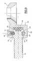
- FIG. 4is a fragmentary enlarged view of the connection between the two screws of FIG. 1;
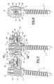
- FIG. 5is an axial cross-sectional view of a modified embodiment of connecting element
- FIG. 6is an exploded view of a modified embodiment of the connection device according to the invention.
- FIG. 6 ′shows the assembly of FIG. 6 mounted, in cross-section on the line VI—VI;
- FIG. 7shows the end of a connection device using the modification of FIG. 6,
- FIG. 8is a cross-sectional view on the line VIII—VIII of the device of FIG. 7 .
- FIG. 1there is shown the connection between two pedicular screws 1 and 2 by a device according to the invention.
- the screws 1 and 2comprise at their upper end a conventional hexagonal head 3 prolonged by a cylindrical bearing 4 screw-threaded at its end 5 (FIG. 2) so as to receive a nut 6 for blocking a ball 7 serving as a ball-bearing, itself held in sandwich fashion between a lower cup 8 and an upper cup 9 , both provided at their center with a hole 10 of a diameter substantially greater than that of the cylindrical bearing 4 , so as to permit free threading of the cups on the bearing as well as a certain radial clearance for the bearing.
- the ball 7is provided with a bore 11 of a diameter corresponding to that of the bearing 4 on which it is also freely threaded.
- the ballis for example spherical and is preferably made of a resiliently compressible material, such as a plastic material, for example polyethylene or polyurethane.
- the cups 8 and 9are of generally concave shape with a surface 12 turned toward the ball 7 of a spherical shape corresponding to the ball or of a truncated conical shape as shown in FIG. 2 .
- the surface 12can be faceted, with six or eight facets for example.
- the external surface 13 of the cupsis for example convex-spherical so as to match respectively one corresponding concave surface that is shaped either ( 14 ) on the hexagonal head 3 , or ( 15 ) on the blocking nut 6 .
- Each of the two screws 1 , 2 being connected to another pedicular screwcomprises a lower cup 8 serving as a first connection with one screw and an upper cup 9 serving as a second connection with another screw.
- Each inter-screw connectionthus comprises two elements generally shown at E 1 and E 2 respectively, which can be brought together or spaced apart by a screw system ensuring their juncture in prolongation of each other.
- the element E 1comprises a block 16 secured to the lower cup 8 laterally and provided with a tapped hole 17 adapted to receive a screw-threaded rod 18 secured to the element E 2 .
- the element E 2comprises a block 19 secured to the upper cup 9 laterally and provided with a cylindrical recess 20 (FIG. 4) adapted to receive a head 21 of generally cylindrical shape provided at the end of the screw-threaded rod 18 .
- the positions of the elements E 1 , E 2can be reversed, the cup 8 of the element E 1 being adapted to be disposed in position with the upper cup and conversely for the cup 9 of the element E 2 .
- the head 21is connected to the screw-threaded rod 18 by an neck 22 of hexagonal cross-section to permit rotation of the screw 18 .
- the head 21is moreover hollow and comprises a cylindrical recess 23 opening axially in the direction of the bottom of the recess 20 .
- a buffer block 24 of resiliently compressible materialfor example of the same material as the ball 7 , is received in the recess 20 and occupies the recess 23 of the head 21 .
- the outer peripheral surface of the head 21is provided with a circular throat 25 , however the block 19 is laterally pierced (FIG. 3) with two parallel blind holes 26 , at the height of the wall of the recess 20 , so as to receive therein two pins 27 for blocking the head 21 .
- the head 21is engaged in the recess 20 and compresses the resilient block 24 .
- connection E 1 , E 2can thus resiliently receive the axial compression and shocks, absorbed by the block 24 .
- the ball connection provided by the ball 7 trapped in sandwich fashion between the lower cup 8 and the upper cup 9permits axial disalignment of the elements E 1 , E 2 which can to a certain extent orient themselves independently in different directions by sliding of the ball 7 of the two opposite taps formed by the cups 8 , 9 , thanks to their diameter 10 substantially greater than that of the bearing 4 on which they are threaded.
- the upper end of the pedicular screws 1 , 2is pierced with a blind hole in which is provided a hollow recess with six sides 28 (FIG. 2 ).
- This impression 28is accessible through the nut 6 by a suitable key so as to block in rotation the screw ( 1 , 2 ) during gripping of the nut 6 .
- the intervertebral connectionthus constituted resiliently absorbs shocks whilst having suitable rigidity, of sufficient flexibility to permit the patient various movements of the torso relative to the pelvis, such as flexure, rotation, which increases all the more the comfort of said patient.
- FIG. 5shows a modification of the resilient securement between the screw-threaded rod 18 and the element E 2 .
- the recess 20 of the block 19is provided on its cylindrical wall with a circular throat 29 of V cross-section, adapted to receive blocking balls 30 disposed both in the throat 29 and in the annular throat 25 of the head 21 , the resilient buffer block 24 being compressed.
- the throat 29is accessible from outside the block 19 by a screw-threaded bore 31 receiving a small block 32 of resilient material occupying the place of a ball 30 and pressed by a screw 33 .
- the balls 30are introduced through the bore 31 into the annular space 25 - 29 , then the bore is closed by elements 32 , 33 .
- the screw 33is gripped once the rod 18 is correctly positioned in its sleeve 16 , to compress the block 32 , thereby preventing effectively any ultimate untimely rotation of the rod 18 in its sleeve 16 .
- the containing-compressing means for the ball of the two end pedicular screwscan be lightened, because there is no other connection, by providing the sandwich grip of the balls in question between the cup of the single connection element and a simple cup serving as a washer interposed between the ball and the hexagonal head of the pedicular screw or the blocking nut of the assembly, as the case may be.
- This simple cupis identical to the cups 8 , 9 except that it is not attached as these latter to the elements 16 , 19 .
- FIG. 7shows a modified embodiment of the invention of which an exploded view is given in FIG. 6 .
- the pedicular screws 1 ′, 2 ′, hexagonal heads 3 ′, bearings 4 ′, balls 7 ′, blocking nuts 6 ′, lower cup 8 ′ and upper cup 9 ′, passage holes 10 ′are substantially identical to the homologous elements of the embodiment of FIG. 1 .
- the sleeve 42is provided with an end collar 44 which is faceted and is retained trapped in the recess 43 , whilst being adapted to pivot about its axis, thanks to a set of balls 45 engaged in two circular channels provided facing the walls of the sleeve 42 and of the hole 43 , respectively.
- the blockage in rotation on itself of the sleeve 42can be obtained with a small block 46 of resilient material inserted between two balls 45 and introduced through a lateral hole 47 in the element E′ 1 .
- This same hole 47is tapped to receive a screw 48 for pressing the resilient block 46 against the sleeve 42 , thereby preventing its rotation.
- the rod 18 ′comprises an enlarged cylindrical head 49 provided on the one hand with a blind hole 50 on its end surface and on the other hand with two parallel lateral flats 51 .
- the head 49is adapted to engage freely in a blind hole 25 provided in the other element E′ 2 while compressing a small cylindrical block 53 of resilient material, introduced previously into the hole 50 and interposed between the bottoms of the two blind holes 50 , 52 .
- the rod 18 ′ which is pressed by the compressed block 53is retained by the pins 54 in contact with the sides 56 (FIGS. 6 and 8) of the cutouts defining the flats 51 .
- the spacing between the elements E′ 1 , E′ 2is adjusted by turning, with the help of a flat key for example, the hexagonal collar 44 of the sleeve 42 , after unlocking the screw 48 of course.
- the rotation of the sleeve 42gives rise to axial displacement of the rod 18 ′ in the sleeve 42 , because the rotation of the rod is prevented by the flats 51 and the pins 54 .
- the rod 18 ′is constantly in resilient abutment against the bottom of the hole 52 , which ensures a certain axial clearance of the rod relative to the element E′ 2 , no matter what the spacing between the elements E′ 1 , E′ 2 .
- the element E′ 1(FIG. 6) is provided in its lower portion with two flat elongations 57 facing each other and adapted, during mounting of the device (FIG. 6 ′), to position themselves against two opposite facets of the hexagonal head 3 ′, thereby mutually immobilizing in rotation the pedicular screw 1 ′ and the inter-screw connection (E′ 1 , 18 ′).
- the inventionis obviously not limited to the embodiments shown and described above, but covers on the contrary all modifications, particularly as to the nature, shape and dimensions of the resiliently recompressible elements ( 7 , 7 ′, 24 , 32 ).
- the balls 7 , 7 ′could be if desired of a rigid material.
Landscapes
- Health & Medical Sciences (AREA)
- Orthopedic Medicine & Surgery (AREA)
- Life Sciences & Earth Sciences (AREA)
- Neurology (AREA)
- Surgery (AREA)
- Heart & Thoracic Surgery (AREA)
- Engineering & Computer Science (AREA)
- Biomedical Technology (AREA)
- Nuclear Medicine, Radiotherapy & Molecular Imaging (AREA)
- Medical Informatics (AREA)
- Molecular Biology (AREA)
- Animal Behavior & Ethology (AREA)
- General Health & Medical Sciences (AREA)
- Public Health (AREA)
- Veterinary Medicine (AREA)
- Prostheses (AREA)
- Surgical Instruments (AREA)
Abstract
Description
The present invention relates to an implantable intervertebral connection device, more particularly adapted to secure together two or more vertebrae.
The invention seeks to replace and maintain according to an arrangement as close as possible to normal, the displaced or deficient vertebrae, particularly in the treatment of certain cases of soliosis, cyphosis, exaggerated lordosis, vertebral instability or substantial decrease of the intervertebral space from whatever the cause.
FromFR 2 698 533 is known an implantable intervertebral connection device permitting two by two connection of several vertebrae with the aid of pedicular screws prolonged by a cylindrical bearing on which is screwed a spherical ferrule of an inter-screw connection element provided with at its other end either with a spherical ferrule or with a spherical-concave cup coacting with a spherical ferrule of a second connection on a same pedicular screw.
The connection element is of the type with a chain and the securement of the assembly is ensured by nuts engaged on the cylindrical bearing ends and pressed against each ferrule or each ferrule-cup assembly as the case may be, against a spherical seat provided on a hexagonal head of the pedicular screw.
If such a device permits adjustment of the intervertebral spacing, both in extension and retraction, by an action on the chain of each inter-screw connection, and if it also permits taking account of the non-parallelism of the axes of the pedicules in situ by an adjustment of the angle formed by the two connections from the same pedicular screw, thanks to the device with a ball ensuring the junction between the screw and the inter-screw connection elements, this intervertebral connection assembly nevertheless has serious drawbacks relating to its rigidity, preventing the patient particularly from flexion or rotation of the torso.
Moreover, the assembly of the components of the system being of metal such as for example titanium alloy, it is difficult to maintain sufficient gripping of the elements of the connection ball and often a posterior intervention for the emplacement of the intervertebral prosthesis will be necessary to reset the screws for blocking said balls.
The present invention seeks to overcome these various drawbacks by providing an implantable intervertebral connection device, adapted to permit not only adjustment of the intervertebral spacing and an adaptation to the angulation of the pedicules relative to each other, but also giving the patient improved comfort by a design of the device giving it suitable elasticity to permit movements of flexure, rotation of the torso and absorbing shocks.
To this end, the invention has for its object an implantable intervertebral connection device comprising at least two pedicular screws provided in their upper portion with a hexagonal head prolonged by a cylindrical bearing and an inter-screw connection of adjustable length, anchored to each end of said bearings, characterized in that said inter-screw connection is constituted on the one hand by a ball threaded on each bearing and, on the other hand, of two connection elements in prolongation of each other and interconnected by a system of screws for adjusting the spacing, the free ends of the elements being shaped as a concave cup skewered on said bearing and matching said ball such that in line with each pedicular screw the ball will be held in sandwich fashion between two cups of two connections associated with the screw, means being provided to move the two cups toward each other to grip said ball and to secure the assembly of the pedicular screw.
Preferably, the ball is of a resiliently deformable material.
The resilient nature of the rotary junction at the level of each pedicular screw permits absorbing the shocks and better distribution of forces along the prosthesis.
The latter not being constituted by a rigid chain but by a string of elements or links all adapted to have at their ends a certain resilient clearance in all directions, including axially of the pedicular screws, the patient thus has the possibility of moving his torso in flexure and rotation relative to the pelvis, of a certain amplitude, by thus outfitting the spine.
Preferably, the screw system connecting the two elements of an inter-screw connection is constituted by a tapped sleeve secured to one of the elements and a coacting screw-threaded rod, connected to the other element by means of a resilient abutment blockage system.
According to a modified embodiment, the screw system connecting the two elements of an inter-screw connection is constituted by a rod provided at one end with a screw-threaded head engaged in a tapping of a sleeve received in one of the above elements and at its other end, with a cylindrical head received in the other of the elements, means being provided, on the one hand, to permit either the free rotation or the blockage in rotation of said sleeve in the carrying element and, on the other hand, to retain and block in rotation said cylindrical head in the carrying element, a resilient abutment being provided between the head and the element.
Such a device not only permits the adjustment of the intervertebral spacing, not only in extension but also in retraction, but ensures a shock-absorbing connection between the two elements of the connection whilst blocking in rotation the screw portion, thereby guaranteeing the desired spacing.
At the two ends of the intervertebral connection device, the containing-gripping means for the ball of the two end pedicular screws can be lightened, because there is no connection with anything else, by providing the sandwiching of the balls in question between the cup of the single connecting element and a simple cup serving as a washer interposed between the ball and the hexagonal head of the pedicular screw or the blocking nut of the assembly, as the case may be.
Or course the cups have a passage hole for the cylindrical bearing of the pedicular screws of a diameter substantially greater than that of said bearing, so as to impart to the cups a certain omnidirectional angular clearance, but the surfaces, respectively of the hexagonal head and of the blocking nut of the assembly, turned toward the ball, are configured in correspondence with the surface facing the cups.
The ball is preferably spherical, but could if desired have another suitable shape, however the surfaces of the cups turned toward the ball are either spherical or truncated conical or else faceted.
Other characteristics and advantages will become clear from the description which follows, of a preferred embodiment of the device of the invention, which description is given solely by way of example and with respect to the accompanying drawings, in which:
FIG. 1 is a side elevational view of a vertical connection device according to the invention;
FIG. 2 is an exploded view of a pedicular screw of the device of FIG. 1, with its two connecting elements;
FIG. 3 shows the possibilities of angular clearance of a device of the type of FIG. 2, once mounted;
FIG. 4 is a fragmentary enlarged view of the connection between the two screws of FIG. 1;
FIG. 5 is an axial cross-sectional view of a modified embodiment of connecting element;
FIG. 6 is an exploded view of a modified embodiment of the connection device according to the invention;
FIG.6′ shows the assembly of FIG. 6 mounted, in cross-section on the line VI—VI;
FIG. 7 shows the end of a connection device using the modification of FIG. 6, and
FIG. 8 is a cross-sectional view on the line VIII—VIII of the device of FIG.7.
In FIG. 1, there is shown the connection between twopedicular screws
Thescrews hexagonal head 3 prolonged by a cylindrical bearing4 screw-threaded at its end5 (FIG. 2) so as to receive anut 6 for blocking aball 7 serving as a ball-bearing, itself held in sandwich fashion between alower cup 8 and anupper cup 9, both provided at their center with ahole 10 of a diameter substantially greater than that of thecylindrical bearing 4, so as to permit free threading of the cups on the bearing as well as a certain radial clearance for the bearing.
Theball 7 is provided with abore 11 of a diameter corresponding to that of thebearing 4 on which it is also freely threaded.
The ball is for example spherical and is preferably made of a resiliently compressible material, such as a plastic material, for example polyethylene or polyurethane.
Thecups surface 12 turned toward theball 7 of a spherical shape corresponding to the ball or of a truncated conical shape as shown in FIG.2. If desired, thesurface 12 can be faceted, with six or eight facets for example.
Theexternal surface 13 of the cups is for example convex-spherical so as to match respectively one corresponding concave surface that is shaped either (14) on thehexagonal head 3, or (15) on theblocking nut 6.
Each of the twoscrews lower cup 8 serving as a first connection with one screw and anupper cup 9 serving as a second connection with another screw.
Each inter-screw connection thus comprises two elements generally shown at E1 and E2 respectively, which can be brought together or spaced apart by a screw system ensuring their juncture in prolongation of each other.
To this end, the element E1 comprises ablock 16 secured to thelower cup 8 laterally and provided with a tappedhole 17 adapted to receive a screw-threadedrod 18 secured to the element E2.
The element E2 comprises ablock 19 secured to theupper cup 9 laterally and provided with a cylindrical recess20 (FIG. 4) adapted to receive ahead 21 of generally cylindrical shape provided at the end of the screw-threadedrod 18.
Of course, the positions of the elements E1, E2 can be reversed, thecup 8 of the element E1 being adapted to be disposed in position with the upper cup and conversely for thecup 9 of the element E2.
Thehead 21 is connected to the screw-threadedrod 18 by anneck 22 of hexagonal cross-section to permit rotation of thescrew 18.
Thehead 21 is moreover hollow and comprises acylindrical recess 23 opening axially in the direction of the bottom of therecess 20.
Abuffer block 24 of resiliently compressible material, for example of the same material as theball 7, is received in therecess 20 and occupies therecess 23 of thehead 21.
The outer peripheral surface of thehead 21 is provided with acircular throat 25, however theblock 19 is laterally pierced (FIG. 3) with two parallelblind holes 26, at the height of the wall of therecess 20, so as to receive therein twopins 27 for blocking thehead 21.
Thehead 21 is engaged in therecess 20 and compresses theresilient block 24.
When thethroat 25 arrives at the height of theholes 26, which is controlled by the rear surface of thehead 21 coming flush with the forward surface of theblock 19, thepins 27 are inserted in theholes 26 and penetrate thethroat 25, on opposite sides of thehead 21. This latter is thus retained trapped and is braked as to rotation because of the resilient pressure of thebuffer block 24.
It is to be noted that the connection E1, E2 can thus resiliently receive the axial compression and shocks, absorbed by theblock 24.
As can be seen in FIG. 3, the ball connection provided by theball 7 trapped in sandwich fashion between thelower cup 8 and theupper cup 9, permits axial disalignment of the elements E1, E2 which can to a certain extent orient themselves independently in different directions by sliding of theball 7 of the two opposite taps formed by thecups diameter 10 substantially greater than that of thebearing 4 on which they are threaded.
When the elements E1, E2 are suitably oriented, with the appropriate intervertebral spacing, thenuts 6 are gripped and resiliently blocked, which prevents any later untimely unlocking.
The configuration of thesurface 12 with the cups according to a truncated conical surface, or if desired faceted, facilitates the axial prepositioning of the cups as well as their emplacement during gripping of thenut 6.
The upper end of thepedicular screws
Thisimpression 28 is accessible through thenut 6 by a suitable key so as to block in rotation the screw (1,2) during gripping of thenut 6.
The intervertebral connection thus constituted resiliently absorbs shocks whilst having suitable rigidity, of sufficient flexibility to permit the patient various movements of the torso relative to the pelvis, such as flexure, rotation, which increases all the more the comfort of said patient.
FIG. 5 shows a modification of the resilient securement between the screw-threadedrod 18 and the element E2. According to this modification, therecess 20 of theblock 19 is provided on its cylindrical wall with acircular throat 29 of V cross-section, adapted to receiveblocking balls 30 disposed both in thethroat 29 and in theannular throat 25 of thehead 21, theresilient buffer block 24 being compressed.
Thethroat 29 is accessible from outside theblock 19 by a screw-threadedbore 31 receiving asmall block 32 of resilient material occupying the place of aball 30 and pressed by ascrew 33. When thehead 21 is in the correctly seated position in therecess 20, theballs 30 are introduced through thebore 31 into the annular space25-29, then the bore is closed byelements screw 33 is gripped once therod 18 is correctly positioned in itssleeve 16, to compress theblock 32, thereby preventing effectively any ultimate untimely rotation of therod 18 in itssleeve 16.
At the two ends of the intervertebral connection device, the containing-compressing means for the ball of the two end pedicular screws can be lightened, because there is no other connection, by providing the sandwich grip of the balls in question between the cup of the single connection element and a simple cup serving as a washer interposed between the ball and the hexagonal head of the pedicular screw or the blocking nut of the assembly, as the case may be.
This simple cup is identical to thecups elements
Such simple cup is shown at40 in FIG. 7, which shows a modified embodiment of the invention of which an exploded view is given in FIG.6.
In this modification, thepedicular screws 1′,2′,hexagonal heads 3′,bearings 4′,balls 7′, blockingnuts 6′,lower cup 8′ andupper cup 9′, passage holes10′, are substantially identical to the homologous elements of the embodiment of FIG.1.
Only the inter-screw connection device E′1 and E′2 and thejunction rod 18′ differ slightly from their homologs in said FIG.1.
Thus, the screw-threadedend 41 of therod 18′ is engaged in a tapping of asleeve 42 introduced into ablind hole 43 provided in the element E′1.
Thesleeve 42 is provided with anend collar 44 which is faceted and is retained trapped in therecess 43, whilst being adapted to pivot about its axis, thanks to a set ofballs 45 engaged in two circular channels provided facing the walls of thesleeve 42 and of thehole 43, respectively.
The blockage in rotation on itself of thesleeve 42 can be obtained with asmall block 46 of resilient material inserted between twoballs 45 and introduced through alateral hole 47 in the element E′1. Thissame hole 47 is tapped to receive ascrew 48 for pressing theresilient block 46 against thesleeve 42, thereby preventing its rotation.
At its other end, therod 18′ comprises an enlargedcylindrical head 49 provided on the one hand with ablind hole 50 on its end surface and on the other hand with twoparallel lateral flats 51.
Thehead 49 is adapted to engage freely in ablind hole 25 provided in the other element E′2 while compressing a smallcylindrical block 53 of resilient material, introduced previously into thehole 50 and interposed between the bottoms of the twoblind holes
The rotation about its axis of therod 18′ is prevented with the help of twopins 54 engaged in twoparallel holes 55 of the element E′2 (FIG. 8) by being trapped in thehole 52 and by engaging themselves in the spaces left by theflats 51.
Therod 18′ which is pressed by thecompressed block 53 is retained by thepins 54 in contact with the sides56 (FIGS. 6 and 8) of the cutouts defining theflats 51.
The spacing between the elements E′1, E′2 is adjusted by turning, with the help of a flat key for example, thehexagonal collar 44 of thesleeve 42, after unlocking thescrew 48 of course. The rotation of thesleeve 42 gives rise to axial displacement of therod 18′ in thesleeve 42, because the rotation of the rod is prevented by theflats 51 and thepins 54. Moreover, therod 18′ is constantly in resilient abutment against the bottom of thehole 52, which ensures a certain axial clearance of the rod relative to the element E′2, no matter what the spacing between the elements E′1, E′2.
It is also to be noted that the element E′1 (FIG. 6) is provided in its lower portion with twoflat elongations 57 facing each other and adapted, during mounting of the device (FIG.6′), to position themselves against two opposite facets of thehexagonal head 3′, thereby mutually immobilizing in rotation thepedicular screw 1′ and the inter-screw connection (E′1,18′).
Finally, the invention is obviously not limited to the embodiments shown and described above, but covers on the contrary all modifications, particularly as to the nature, shape and dimensions of the resiliently recompressible elements (7,7′,24,32). The shapes and dimensions of thecups rod
It is particularly to be noted that according to its use, theballs
Claims (17)
1. Implantable intervertebral connection device comprising at least two pedicular screws (1,2;1′,2′) provided in their upper portion with a hexagonal head (3,3′) surmounted by a cylindrical bearing (4,4′) and an inter-screw connection of adjustable length anchored at each end to said bearings, said inter-screw connection being constituted by a ball (7,7′) engaged on each bearing (4) and by two connection elements (E1, E2; E′1, E′2) in prolongation of each other and interconnected by a screw system (17,18;18′,41,42) for the adjustment of spacing, both free ends of each element being shaped as concave cups (8,9;8′,9′) engaged on said bearing (4,4′) and mating with said ball (7,7′) such that in line with each pedicular screw (1,2;1′,2′) the ball will be held in sandwich fashion between two said cups (8,9;8′,9′) of two connections associated with the screw, means (6,6′) being provided to bring together the two cups (8,9;8′,9′) by gripping said ball (7,7′) and securing together the assembly of the pedicular screw.
2. Device according toclaim 1 , characterized in that the ball (7,7′) is of a resiliently deformable material.
3. Device according toclaim 1 , characterized in that said screw system connecting the two elements (E1, E2) of one inter-screw connection is constituted by a tapped sleeve (16) secured to one of the elements and by a coacting screw-threaded rod (18), connected to the other element by means of a system of blocking with a resilient abutment (24).
4. Device according toclaim 3 , characterized in that said rod (18,18′) has a head (21,49) in resilient abutment against a recess (20,52) of said element (E2, E′2), means being provided to retain and block in rotation said head (21,49) in said recess (20,52).
5. Device according toclaim 4 , characterized in that said retaining-blocking means of the head (21,49) are constituted by pins (29,54) for retaining said head (21,49) in a position of compression by a block (24,53) of a resiliently compressible material disposed in said recess (20,52).
6. Device according toclaim 4 , characterized in that said retaining-blocking means of the head (21) are constituted by a set of balls (30) interposed between the head (21) and its recess (20) and retaining the head in a position for compression of a block (24) of a resiliently compressible material disposed in said recess (20), a blockage in rotation of said head (21) being nevertheless ensured by a lateral screw (33) having a block (32) of resiliently compressible material against said head (21).
7. Device according toclaim 4 , characterized in that said retaining-blocking means of the cylindrical head (49) are constituted by a set of pins (54) coacting with flats (51) provided on said head (29) so as to block in rotation said rod (18′).
8. Device according toclaim 3 , characterized in that between the screw-threaded rod (18) and the head (21) is provided a hexagonal section (22) to ensure the rotation of the screw-threaded rod (18) in its sleeve (16).
9. Device according toclaim 1 , characterized in that said screw system connecting the two elements (E′1, E′2) of an inter-screw connection is constituted by a rod (18′) provided at one end with a screw-threaded head (41) engaged in a sleeve (42) received in one (E′1) of the two above elements and at its other end with a cylindrical head (49) received in the other (E′2) of the elements, means being provided, on the one hand, to permit either the free rotation or the blockage in rotation of said sleeve (42) in the carrying element (E′1) and, on the other hand, to retain in blocking rotation said cylindrical head (49) in the carrying element (E′2), a resilient abutment (53) being provided between the head and the carrying element.
10. Device according toclaim 9 , characterized in that said sleeve (42) has an external collar (45) permitting the rotation of the sleeve in its recess (43).
11. Device according toclaim 1 , characterized in that said cups (8,9;8′,9′) have a hole (10,10′) for passage of the cylindrical bearing (4,4′) of the pedicular screws (1,2;1′,2′), of a diameter substantially greater than that of said bearing.
12. Device according toclaim 1 , characterized in that said means to bring together the cups (8,9;8′,9′) and to secure the assembly of the pedicular screw (1,2;1′,2′) are constituted by a blocking nut (6,6′) screwed on the screw-threaded end (5) of said bearing (4,4′).
13. Device according toclaim 12 , characterized in that the respective surfaces (14,15) of a hexagonal head (3,3′) and of the nut (6,6′) for blocking the assembly, turn toward the ball (7,7′), are shaped in correspondence with the facing surface of the cups (8,9;8′,9′).
14. Device according toclaim 1 , characterized in that the ball (7;7′) is spherical.
15. Device according toclaim 1 , characterized in that the surface (12) of the cups (8,9;8′,9′) turn toward the ball (7,7′) have a spherical, truncated conical or faceted surface.
16. Device according to oneclaim 1 , characterized in that the connection element (E′1) turned toward the hexagonal head (3′) of the pedicular screw (1′) comprises two lower prolongations (57) facing each other and adapted to coact with said hexagonal head (3′) to immobilize in rotation the latter.
17. Device according to oneclaim 1 , characterized in that at the level of the two end pedicular screws of the intervertebral connection, the gripping of the ball (7′) is ensured between the cup (8′) of the end connection element (E′2) and a simple cup (40) serving as a washer interposed between the ball and the hexagonal head (3′) of the screw or blocking screw (6′) of the screw assembly.
Applications Claiming Priority (2)
| Application Number | Priority Date | Filing Date | Title |
|---|---|---|---|
| FR9909981AFR2796828B1 (en) | 1999-07-27 | 1999-07-27 | IMPLANTABLE INTERVERTEBRAL CONNECTION DEVICE |
| FR9909981 | 1999-07-27 |
Publications (1)
| Publication Number | Publication Date |
|---|---|
| US6626904B1true US6626904B1 (en) | 2003-09-30 |
Family
ID=9548759
Family Applications (1)
| Application Number | Title | Priority Date | Filing Date |
|---|---|---|---|
| US09/627,128Expired - Fee RelatedUS6626904B1 (en) | 1999-07-27 | 2000-07-27 | Implantable intervertebral connection device |
Country Status (3)
| Country | Link |
|---|---|
| US (1) | US6626904B1 (en) |
| EP (1) | EP1072228A1 (en) |
| FR (1) | FR2796828B1 (en) |
Cited By (131)
| Publication number | Priority date | Publication date | Assignee | Title |
|---|---|---|---|---|
| US20040260287A1 (en)* | 2001-03-26 | 2004-12-23 | Nuvasive, Inc. | Spinal alignment system and related methods |
| US20050085813A1 (en)* | 2003-10-21 | 2005-04-21 | Innovative Spinal Technologies | System and method for stabilizing of internal structures |
| US20050135874A1 (en)* | 2001-11-27 | 2005-06-23 | Renishaw Plc | Adjustable device |
| US20050149023A1 (en)* | 2001-09-28 | 2005-07-07 | Stephen Ritland | Adjustable rod and connector device and method of use |
| US20050177166A1 (en)* | 2003-05-02 | 2005-08-11 | Timm Jens P. | Mounting mechanisms for pedicle screws and related assemblies |
| US20050177164A1 (en)* | 2003-05-02 | 2005-08-11 | Carmen Walters | Pedicle screw devices, systems and methods having a preloaded set screw |
| US20050182401A1 (en)* | 2003-05-02 | 2005-08-18 | Timm Jens P. | Systems and methods for spine stabilization including a dynamic junction |
| US20050182409A1 (en)* | 2003-05-02 | 2005-08-18 | Ronald Callahan | Systems and methods accommodating relative motion in spine stabilization |
| US20050187548A1 (en)* | 2004-01-13 | 2005-08-25 | Butler Michael S. | Pedicle screw constructs for spine fixation systems |
| US20060025770A1 (en)* | 2002-12-06 | 2006-02-02 | Fridolin Schlapfer | Device for stabilizing bones |
| US20060064088A1 (en)* | 2002-04-04 | 2006-03-23 | Stephane Ramare | Spinal ostesynthesis system |
| US20060079896A1 (en)* | 2004-09-30 | 2006-04-13 | Depuy Spine, Inc. | Methods and devices for posterior stabilization |
| US20060079899A1 (en)* | 2001-09-28 | 2006-04-13 | Stephen Ritland | Connection rod for screw or hook polyaxial system and method of use |
| US20060085076A1 (en)* | 2004-10-15 | 2006-04-20 | Manoj Krishna | Posterior spinal arthroplasty-development of a new posteriorly inserted artificial disc and an artificial facet joint |
| US20060106380A1 (en)* | 2003-10-21 | 2006-05-18 | Innovative Spinal Technologies | Extension for use with stabilization systems for internal structures |
| US20060195096A1 (en)* | 2005-02-09 | 2006-08-31 | David Lee | Bone fixation apparatus |
| US20060200130A1 (en)* | 2005-02-18 | 2006-09-07 | Hawkins Nathaniel E | Spinal fixation device and associated method |
| US20060206114A1 (en)* | 2004-11-19 | 2006-09-14 | Alphaspine, Inc. | Rod coupling assemblies |
| US20060247635A1 (en)* | 2003-08-05 | 2006-11-02 | Gordon Charles R | Dynamic posterior stabilization systems and methods of use |
| US20060254784A1 (en)* | 2003-09-08 | 2006-11-16 | Stephan Hartmann | Longitudinal support |
| US20060265074A1 (en)* | 2004-10-21 | 2006-11-23 | Manoj Krishna | Posterior spinal arthroplasty-development of a new posteriorly inserted artificial disc, a new anteriorly inserted artifical disc and an artificial facet joint |
| US20060271046A1 (en)* | 2004-12-30 | 2006-11-30 | Kwak Seungkyu Daniel | Facet joint replacement |
| US20070173822A1 (en)* | 2006-01-13 | 2007-07-26 | Sdgi Holdings, Inc. | Use of a posterior dynamic stabilization system with an intradiscal device |
| US20070198014A1 (en)* | 2006-02-07 | 2007-08-23 | Sdgi Holdings, Inc. | Articulating connecting member and anchor systems for spinal stabilization |
| US20070213720A1 (en)* | 2006-03-08 | 2007-09-13 | Southwest Research Institute | Dynamic interbody device |
| US20070288012A1 (en)* | 2006-04-21 | 2007-12-13 | Dennis Colleran | Dynamic motion spinal stabilization system and device |
| US20070288011A1 (en)* | 2006-04-18 | 2007-12-13 | Joseph Nicholas Logan | Spinal Rod System |
| US20080140075A1 (en)* | 2006-12-07 | 2008-06-12 | Ensign Michael D | Press-On Pedicle Screw Assembly |
| US20080177318A1 (en)* | 2007-01-18 | 2008-07-24 | Warsaw Orthopedic, Inc. | Vertebral Stabilizer |
| US20080195208A1 (en)* | 2007-02-09 | 2008-08-14 | Altiva Corporation | Dynamic stabilization device |
| US20080255617A1 (en)* | 2006-12-21 | 2008-10-16 | Paul Cho | Vertebral Support Device |
| US20080262554A1 (en)* | 2004-10-20 | 2008-10-23 | Stanley Kyle Hayes | Dyanamic rod |
| US7455639B2 (en) | 2004-09-20 | 2008-11-25 | Stephen Ritland | Opposing parallel bladed retractor and method of use |
| US20080294194A1 (en)* | 2007-05-22 | 2008-11-27 | Marco Dagoberto Capote | Spinal stabilization systems and methods |
| DE102007033219A1 (en)* | 2007-07-17 | 2009-01-22 | Aesculap Ag | Orthopedic holding system for fixing vertebral body, has clamping screw for pressing end sections against walls of retaining opening, when clamping screw is screwed into opening, such that clamping screw is fixed against heads of screws |
| US20090030465A1 (en)* | 2004-10-20 | 2009-01-29 | Moti Altarac | Dynamic rod |
| US20090069849A1 (en)* | 2007-09-10 | 2009-03-12 | Oh Younghoon | Dynamic screw system |
| US7507248B2 (en) | 2001-04-06 | 2009-03-24 | Ldr Medical | Spinal osteosynthesis device and preparation method |
| US20090093819A1 (en)* | 2007-10-05 | 2009-04-09 | Abhijeet Joshi | Anisotropic spinal stabilization rod |
| US20090105763A1 (en)* | 2007-10-17 | 2009-04-23 | X-Spine Systems, Inc. | Cross connector apparatus for spinal fixation rods |
| US20090131984A1 (en)* | 2007-11-19 | 2009-05-21 | Linares Miguel A | Spine support implant including inter vertebral insertable fluid ballastable insert and inter-vertebral web retaining harnesses |
| US7569061B2 (en) | 2004-11-16 | 2009-08-04 | Innovative Spinal Technologies, Inc. | Off-axis anchor guidance system |
| US7578849B2 (en) | 2006-01-27 | 2009-08-25 | Warsaw Orthopedic, Inc. | Intervertebral implants and methods of use |
| US20090228045A1 (en)* | 2004-10-20 | 2009-09-10 | Stanley Kyle Hayes | Dynamic rod |
| US20090248077A1 (en)* | 2008-03-31 | 2009-10-01 | Derrick William Johns | Hybrid dynamic stabilization |
| US20090254125A1 (en)* | 2008-04-03 | 2009-10-08 | Daniel Predick | Top Loading Polyaxial Spine Screw Assembly With One Step Lockup |
| US20090254123A1 (en)* | 2003-12-31 | 2009-10-08 | Spine Wave, Inc. | Dynamic Spinal Stabilization System |
| US20090275986A1 (en)* | 2008-05-05 | 2009-11-05 | Warsaw Orthopedic, Inc. | Flexible spinal stabilization element and system |
| US7641673B2 (en) | 2000-07-25 | 2010-01-05 | Zimmer Spine, S.A.S. | Flexible linking piece for stabilising the spine |
| US20100036423A1 (en)* | 2004-10-20 | 2010-02-11 | Stanley Kyle Hayes | Dynamic rod |
| US20100063545A1 (en)* | 2008-09-09 | 2010-03-11 | Richelsoph Marc E | Polyaxial screw assembly |
| US7682375B2 (en) | 2002-05-08 | 2010-03-23 | Stephen Ritland | Dynamic fixation device and method of use |
| US7682376B2 (en) | 2006-01-27 | 2010-03-23 | Warsaw Orthopedic, Inc. | Interspinous devices and methods of use |
| US20100087880A1 (en)* | 2004-02-17 | 2010-04-08 | Facet Solutions, Inc. | Facet Joint Replacement Instruments and Methods |
| US7708778B2 (en) | 2003-08-05 | 2010-05-04 | Flexuspine, Inc. | Expandable articulating intervertebral implant with cam |
| US7753939B2 (en) | 2000-06-30 | 2010-07-13 | Stephen Ritland | Polyaxial connection device and method |
| US7763047B2 (en) | 2002-02-20 | 2010-07-27 | Stephen Ritland | Pedicle screw connector apparatus and method |
| US7766943B1 (en)* | 2005-08-11 | 2010-08-03 | Medicine Lodge Inc. | Modular percutaneous spinal fusion system and method |
| US7766940B2 (en) | 2004-12-30 | 2010-08-03 | Depuy Spine, Inc. | Posterior stabilization system |
| US20100217334A1 (en)* | 2009-02-23 | 2010-08-26 | Hawkes David T | Press-On Link For Surgical Screws |
| US20100234958A1 (en)* | 2007-11-19 | 2010-09-16 | Linares Medical Devices, Llc | Combination spacer insert and support for providing inter-cervical vertebral support |
| US7815663B2 (en) | 2006-01-27 | 2010-10-19 | Warsaw Orthopedic, Inc. | Vertebral rods and methods of use |
| US20100298882A1 (en)* | 2009-05-20 | 2010-11-25 | Spine Wave, Inc. | Multi-Axial Cross Connector |
| US20100318131A1 (en)* | 2009-06-10 | 2010-12-16 | Spine Wave, Inc. | Devices and Methods for Adding an Additional Level of Fixation to an Existing Construct |
| US7854752B2 (en) | 2004-08-09 | 2010-12-21 | Theken Spine, Llc | System and method for dynamic skeletal stabilization |
| US20100331886A1 (en)* | 2009-06-25 | 2010-12-30 | Jonathan Fanger | Posterior Dynamic Stabilization Device Having A Mobile Anchor |
| US20110009910A1 (en)* | 2004-11-10 | 2011-01-13 | Jackson Roger P | Polyaxial bone screw with helically wound capture connection |
| US7896902B2 (en) | 2006-04-05 | 2011-03-01 | Dong Myung Jeon | Multi-axial double locking bone screw assembly |
| US7909869B2 (en) | 2003-08-05 | 2011-03-22 | Flexuspine, Inc. | Artificial spinal unit assemblies |
| US7935134B2 (en) | 2004-10-20 | 2011-05-03 | Exactech, Inc. | Systems and methods for stabilization of bone structures |
| US7959677B2 (en) | 2007-01-19 | 2011-06-14 | Flexuspine, Inc. | Artificial functional spinal unit system and method for use |
| US7959564B2 (en) | 2006-07-08 | 2011-06-14 | Stephen Ritland | Pedicle seeker and retractor, and methods of use |
| US7967826B2 (en) | 2003-10-21 | 2011-06-28 | Theken Spine, Llc | Connector transfer tool for internal structure stabilization systems |
| US7985244B2 (en) | 2004-09-30 | 2011-07-26 | Depuy Spine, Inc. | Posterior dynamic stabilizer devices |
| US7993373B2 (en)* | 2005-02-22 | 2011-08-09 | Hoy Robert W | Polyaxial orthopedic fastening apparatus |
| US7998175B2 (en) | 2004-10-20 | 2011-08-16 | The Board Of Trustees Of The Leland Stanford Junior University | Systems and methods for posterior dynamic stabilization of the spine |
| US8012182B2 (en) | 2000-07-25 | 2011-09-06 | Zimmer Spine S.A.S. | Semi-rigid linking piece for stabilizing the spine |
| US8021399B2 (en)* | 2005-07-19 | 2011-09-20 | Stephen Ritland | Rod extension for extending fusion construct |
| US8025681B2 (en) | 2006-03-29 | 2011-09-27 | Theken Spine, Llc | Dynamic motion spinal stabilization system |
| US8025680B2 (en) | 2004-10-20 | 2011-09-27 | Exactech, Inc. | Systems and methods for posterior dynamic stabilization of the spine |
| US8096996B2 (en) | 2007-03-20 | 2012-01-17 | Exactech, Inc. | Rod reducer |
| US8118840B2 (en) | 2009-02-27 | 2012-02-21 | Warsaw Orthopedic, Inc. | Vertebral rod and related method of manufacture |
| US8157844B2 (en) | 2007-10-22 | 2012-04-17 | Flexuspine, Inc. | Dampener system for a posterior stabilization system with a variable length elongated member |
| US8162994B2 (en) | 2007-10-22 | 2012-04-24 | Flexuspine, Inc. | Posterior stabilization system with isolated, dual dampener systems |
| US8182514B2 (en) | 2007-10-22 | 2012-05-22 | Flexuspine, Inc. | Dampener system for a posterior stabilization system with a fixed length elongated member |
| US8187330B2 (en) | 2007-10-22 | 2012-05-29 | Flexuspine, Inc. | Dampener system for a posterior stabilization system with a variable length elongated member |
| CN102525623A (en)* | 2006-12-10 | 2012-07-04 | 帕拉迪格脊骨有限责任公司 | Posterior functionally dynamic stabilization system |
| US8221457B2 (en)* | 2001-10-18 | 2012-07-17 | Ldr Medical | Progressive approach osteosynthesis device and preassembly method |
| US8226690B2 (en) | 2005-07-22 | 2012-07-24 | The Board Of Trustees Of The Leland Stanford Junior University | Systems and methods for stabilization of bone structures |
| US20120203278A1 (en)* | 2011-02-04 | 2012-08-09 | Warsaw Orthopedic, Inc. | Crosslink Devices for a Growing Spinal Column Segment |
| US8262571B2 (en) | 2003-05-22 | 2012-09-11 | Stephen Ritland | Intermuscular guide for retractor insertion and method of use |
| US8267965B2 (en) | 2007-10-22 | 2012-09-18 | Flexuspine, Inc. | Spinal stabilization systems with dynamic interbody devices |
| US8267969B2 (en) | 2004-10-20 | 2012-09-18 | Exactech, Inc. | Screw systems and methods for use in stabilization of bone structures |
| US8337532B1 (en) | 2011-12-08 | 2012-12-25 | Spine Wave, Inc. | Methods for percutaneously extending an existing spinal construct |
| US8343219B2 (en) | 2007-06-08 | 2013-01-01 | Ldr Medical | Intersomatic cage, intervertebral prosthesis, anchoring device and implantation instruments |
| US8357181B2 (en) | 2005-10-27 | 2013-01-22 | Warsaw Orthopedic, Inc. | Intervertebral prosthetic device for spinal stabilization and method of implanting same |
| US8388660B1 (en) | 2006-08-01 | 2013-03-05 | Samy Abdou | Devices and methods for superior fixation of orthopedic devices onto the vertebral column |
| US8523865B2 (en) | 2005-07-22 | 2013-09-03 | Exactech, Inc. | Tissue splitter |
| US8523912B2 (en) | 2007-10-22 | 2013-09-03 | Flexuspine, Inc. | Posterior stabilization systems with shared, dual dampener systems |
| US20140074166A1 (en)* | 2012-09-11 | 2014-03-13 | Mercy Medical Research Institute | Spinous process fixation device and systems |
| US8758439B2 (en) | 2007-11-19 | 2014-06-24 | Linares Medical Devices, Llc | Spine support implant including inter vertebral insertable fluid ballastable insert and inter-vertebral web retaining harnesses |
| US8894687B2 (en) | 2011-04-25 | 2014-11-25 | Nexus Spine, L.L.C. | Coupling system for surgical construct |
| US8932334B2 (en) | 2002-04-05 | 2015-01-13 | Stephen Ritland | Dynamic fixation device and method of use |
| US8940051B2 (en) | 2011-03-25 | 2015-01-27 | Flexuspine, Inc. | Interbody device insertion systems and methods |
| US20150034766A1 (en)* | 2013-08-01 | 2015-02-05 | Airbus Operations (S.A.S) | Tool for simultaneously holding several attachment clips in contact with an aircraft fuselage frame element |
| US9011494B2 (en) | 2009-09-24 | 2015-04-21 | Warsaw Orthopedic, Inc. | Composite vertebral rod system and methods of use |
| US9060813B1 (en) | 2008-02-29 | 2015-06-23 | Nuvasive, Inc. | Surgical fixation system and related methods |
| US9198696B1 (en) | 2010-05-27 | 2015-12-01 | Nuvasive, Inc. | Cross-connector and related methods |
| US9247964B1 (en) | 2011-03-01 | 2016-02-02 | Nuasive, Inc. | Spinal Cross-connector |
| US9326795B2 (en) | 2001-12-12 | 2016-05-03 | Ldr Medical | Implant for osseous anchoring with polyaxial head |
| US9387013B1 (en) | 2011-03-01 | 2016-07-12 | Nuvasive, Inc. | Posterior cervical fixation system |
| US9456851B2 (en) | 2007-10-23 | 2016-10-04 | Intelligent Implant Systems, Llc | Spinal implant |
| US9492288B2 (en) | 2013-02-20 | 2016-11-15 | Flexuspine, Inc. | Expandable fusion device for positioning between adjacent vertebral bodies |
| US9517144B2 (en) | 2014-04-24 | 2016-12-13 | Exactech, Inc. | Limited profile intervertebral implant with incorporated fastening mechanism |
| US9526627B2 (en) | 2011-11-17 | 2016-12-27 | Exactech, Inc. | Expandable interbody device system and method |
| US9526531B2 (en) | 2013-10-07 | 2016-12-27 | Intelligent Implant Systems, Llc | Polyaxial plate rod system and surgical procedure |
| US9532808B2 (en) | 2013-09-16 | 2017-01-03 | Aesculap Ag | Connection element and spine stabilization system |
| US9675389B2 (en) | 2009-12-07 | 2017-06-13 | Samy Abdou | Devices and methods for minimally invasive spinal stabilization and instrumentation |
| US9745043B2 (en) | 2013-08-01 | 2017-08-29 | Airbus Operations (S.A.S.) | Aircraft fuselage frame element integrating tabs for the fastening of stiffeners |
| US10362982B2 (en) | 2017-04-28 | 2019-07-30 | Warsaw Orthopedic, Inc. | Spinal implant system and method |
| US10398565B2 (en) | 2014-04-24 | 2019-09-03 | Choice Spine, Llc | Limited profile intervertebral implant with incorporated fastening and locking mechanism |
| US10548740B1 (en) | 2016-10-25 | 2020-02-04 | Samy Abdou | Devices and methods for vertebral bone realignment |
| US10575961B1 (en) | 2011-09-23 | 2020-03-03 | Samy Abdou | Spinal fixation devices and methods of use |
| US10695105B2 (en) | 2012-08-28 | 2020-06-30 | Samy Abdou | Spinal fixation devices and methods of use |
| US10857003B1 (en) | 2015-10-14 | 2020-12-08 | Samy Abdou | Devices and methods for vertebral stabilization |
| US10918498B2 (en) | 2004-11-24 | 2021-02-16 | Samy Abdou | Devices and methods for inter-vertebral orthopedic device placement |
| US10973648B1 (en) | 2016-10-25 | 2021-04-13 | Samy Abdou | Devices and methods for vertebral bone realignment |
| US11006982B2 (en) | 2012-02-22 | 2021-05-18 | Samy Abdou | Spinous process fixation devices and methods of use |
| US11173040B2 (en) | 2012-10-22 | 2021-11-16 | Cogent Spine, LLC | Devices and methods for spinal stabilization and instrumentation |
| US11179248B2 (en) | 2018-10-02 | 2021-11-23 | Samy Abdou | Devices and methods for spinal implantation |
| US11331125B1 (en) | 2021-10-07 | 2022-05-17 | Ortho Inventions, Llc | Low profile rod-to-rod coupler |
Families Citing this family (6)
| Publication number | Priority date | Publication date | Assignee | Title |
|---|---|---|---|---|
| US7473267B2 (en)* | 2003-04-25 | 2009-01-06 | Warsaw Orthopedic, Inc. | System and method for minimally invasive posterior fixation |
| US7833251B1 (en) | 2004-01-06 | 2010-11-16 | Nuvasive, Inc. | System and method for performing spinal fixation |
| EP2007297A1 (en)* | 2006-03-29 | 2008-12-31 | Innovative Spinal Technologies, Inc. | Dynamic motion spinal stabilization system |
| WO2008134703A2 (en) | 2007-04-30 | 2008-11-06 | Globus Medical, Inc. | Flexible spine stabilization system |
| FR2924014B1 (en)* | 2007-11-22 | 2010-01-22 | Henry Graf | DEVICE FOR CONNECTING AT LEAST THREE VERTEBRATES BETWEEN THEM |
| EP2911599B1 (en)* | 2012-10-23 | 2020-04-29 | Nexus Spine, L.L.C. | Surgical construct coupling system |
Citations (13)
| Publication number | Priority date | Publication date | Assignee | Title |
|---|---|---|---|---|
| DE3841008A1 (en) | 1988-12-06 | 1990-06-07 | Heinrich Ulrich | Implant for correction of the spine |
| DE9004960U1 (en) | 1990-05-02 | 1991-08-29 | Pfeil, Joachim, Dr.Med. | Halo fixator for the treatment of cervical spine diseases and injuries |
| US5084048A (en)* | 1989-07-12 | 1992-01-28 | Sulzer Brothers Limited | Implant for vertebrae with spinal stabilizer |
| US5196013A (en) | 1989-11-03 | 1993-03-23 | Harms Juergen | Pedicel screw and correcting and supporting apparatus comprising such screw |
| FR2697428A1 (en) | 1992-11-02 | 1994-05-06 | Alby Albert | Flexible connecting implant for supporting and aligning vertebrae - comprises shaft and cage components, each having spherical head with conical through passage, connected by intermediate springs |
| US5330474A (en)* | 1991-09-23 | 1994-07-19 | Lin Chih I | Vertebral locking and retrieving system |
| US5468241A (en) | 1988-02-18 | 1995-11-21 | Howmedica Gmbh | Support device for the human vertebral column |
| US5613968A (en)* | 1995-05-01 | 1997-03-25 | Lin; Chih-I | Universal pad fixation device for orthopedic surgery |
| US5735851A (en)* | 1996-10-09 | 1998-04-07 | Third Millennium Engineering, Llc | Modular polyaxial locking pedicle screw |
| US5961516A (en)* | 1996-08-01 | 1999-10-05 | Graf; Henry | Device for mechanically connecting and assisting vertebrae with respect to one another |
| US6083226A (en)* | 1998-04-22 | 2000-07-04 | Fiz; Daniel | Bone fixation device and transverse linking bridge |
| US6187005B1 (en)* | 1998-09-11 | 2001-02-13 | Synthes (Usa) | Variable angle spinal fixation system |
| US6273914B1 (en)* | 1995-09-28 | 2001-08-14 | Sparta, Inc. | Spinal implant |
Family Cites Families (1)
| Publication number | Priority date | Publication date | Assignee | Title |
|---|---|---|---|---|
| FR2698533A1 (en) | 1992-11-27 | 1994-06-03 | Alby Albert | Modular connection assembly for vertebral support implant - comprises pedicular screws connected by spherical heads and adjustable connecting blocks, with locking nuts securing in selected positions |
- 1999
- 1999-07-27FRFR9909981Apatent/FR2796828B1/ennot_activeExpired - Fee Related
- 2000
- 2000-07-25EPEP00450013Apatent/EP1072228A1/ennot_activeWithdrawn
- 2000-07-27USUS09/627,128patent/US6626904B1/ennot_activeExpired - Fee Related
Patent Citations (13)
| Publication number | Priority date | Publication date | Assignee | Title |
|---|---|---|---|---|
| US5468241A (en) | 1988-02-18 | 1995-11-21 | Howmedica Gmbh | Support device for the human vertebral column |
| DE3841008A1 (en) | 1988-12-06 | 1990-06-07 | Heinrich Ulrich | Implant for correction of the spine |
| US5084048A (en)* | 1989-07-12 | 1992-01-28 | Sulzer Brothers Limited | Implant for vertebrae with spinal stabilizer |
| US5196013A (en) | 1989-11-03 | 1993-03-23 | Harms Juergen | Pedicel screw and correcting and supporting apparatus comprising such screw |
| DE9004960U1 (en) | 1990-05-02 | 1991-08-29 | Pfeil, Joachim, Dr.Med. | Halo fixator for the treatment of cervical spine diseases and injuries |
| US5330474A (en)* | 1991-09-23 | 1994-07-19 | Lin Chih I | Vertebral locking and retrieving system |
| FR2697428A1 (en) | 1992-11-02 | 1994-05-06 | Alby Albert | Flexible connecting implant for supporting and aligning vertebrae - comprises shaft and cage components, each having spherical head with conical through passage, connected by intermediate springs |
| US5613968A (en)* | 1995-05-01 | 1997-03-25 | Lin; Chih-I | Universal pad fixation device for orthopedic surgery |
| US6273914B1 (en)* | 1995-09-28 | 2001-08-14 | Sparta, Inc. | Spinal implant |
| US5961516A (en)* | 1996-08-01 | 1999-10-05 | Graf; Henry | Device for mechanically connecting and assisting vertebrae with respect to one another |
| US5735851A (en)* | 1996-10-09 | 1998-04-07 | Third Millennium Engineering, Llc | Modular polyaxial locking pedicle screw |
| US6083226A (en)* | 1998-04-22 | 2000-07-04 | Fiz; Daniel | Bone fixation device and transverse linking bridge |
| US6187005B1 (en)* | 1998-09-11 | 2001-02-13 | Synthes (Usa) | Variable angle spinal fixation system |
Cited By (275)
| Publication number | Priority date | Publication date | Assignee | Title |
|---|---|---|---|---|
| US7753939B2 (en) | 2000-06-30 | 2010-07-13 | Stephen Ritland | Polyaxial connection device and method |
| US7641673B2 (en) | 2000-07-25 | 2010-01-05 | Zimmer Spine, S.A.S. | Flexible linking piece for stabilising the spine |
| US8012182B2 (en) | 2000-07-25 | 2011-09-06 | Zimmer Spine S.A.S. | Semi-rigid linking piece for stabilizing the spine |
| US20040260287A1 (en)* | 2001-03-26 | 2004-12-23 | Nuvasive, Inc. | Spinal alignment system and related methods |
| US7507248B2 (en) | 2001-04-06 | 2009-03-24 | Ldr Medical | Spinal osteosynthesis device and preparation method |
| US9622790B2 (en) | 2001-09-19 | 2017-04-18 | Warsaw Orthopedic, Inc. | Rod extension for extending fusion construct |
| US7655025B2 (en)* | 2001-09-28 | 2010-02-02 | Stephen Ritland | Adjustable rod and connector device and method of use |
| US7695498B2 (en)* | 2001-09-28 | 2010-04-13 | Stephen Ritland | Connection rod for screw or hook polyaxial system and method of use |
| US20100137914A1 (en)* | 2001-09-28 | 2010-06-03 | Stephen Ritland | Adjustable rod and connector device |
| US20050149023A1 (en)* | 2001-09-28 | 2005-07-07 | Stephen Ritland | Adjustable rod and connector device and method of use |
| US20060079899A1 (en)* | 2001-09-28 | 2006-04-13 | Stephen Ritland | Connection rod for screw or hook polyaxial system and method of use |
| US7985245B2 (en)* | 2001-09-28 | 2011-07-26 | Stephen Ritland | Connection rod for screw or hook polyaxial system and method of use |
| US20070162006A1 (en)* | 2001-09-28 | 2007-07-12 | Stephen Ritland | Connection Rod for Screw or Hook Polyaxial System and Method of Use |
| US7207992B2 (en)* | 2001-09-28 | 2007-04-24 | Stephen Ritland | Connection rod for screw or hook polyaxial system and method of use |
| US8221457B2 (en)* | 2001-10-18 | 2012-07-17 | Ldr Medical | Progressive approach osteosynthesis device and preassembly method |
| US7337685B2 (en) | 2001-11-27 | 2008-03-04 | Renishaw Plc | Adjustable device |
| US20050135874A1 (en)* | 2001-11-27 | 2005-06-23 | Renishaw Plc | Adjustable device |
| US9326795B2 (en) | 2001-12-12 | 2016-05-03 | Ldr Medical | Implant for osseous anchoring with polyaxial head |
| US8221459B2 (en) | 2002-02-20 | 2012-07-17 | Stephen Ritland | Pedicle screw connector apparatus and method |
| US7763047B2 (en) | 2002-02-20 | 2010-07-27 | Stephen Ritland | Pedicle screw connector apparatus and method |
| US7569068B2 (en)* | 2002-04-04 | 2009-08-04 | Kiscomedica | Spinal osteosynthesis system |
| US20060064088A1 (en)* | 2002-04-04 | 2006-03-23 | Stephane Ramare | Spinal ostesynthesis system |
| US8932334B2 (en) | 2002-04-05 | 2015-01-13 | Stephen Ritland | Dynamic fixation device and method of use |
| US7682375B2 (en) | 2002-05-08 | 2010-03-23 | Stephen Ritland | Dynamic fixation device and method of use |
| US8486111B2 (en) | 2002-05-08 | 2013-07-16 | Stephen Ritland | Dynamic fixation device and method of use |
| US8585739B2 (en) | 2002-05-08 | 2013-11-19 | Stephen Ritland | Dynamic fixation device and method of use |
| US8685062B2 (en) | 2002-05-08 | 2014-04-01 | Stephen Ritland | Dynamic fixation device and method of use |
| US8690922B2 (en) | 2002-05-08 | 2014-04-08 | Stephen Ritland | Dynamic fixation device and method of use |
| US9232967B2 (en) | 2002-05-08 | 2016-01-12 | Stephen Ritland | Dynamic fixation device and method of use |
| US9918744B2 (en) | 2002-05-08 | 2018-03-20 | Stephen Ritland | Dynamic fixation device and method of use |
| US20060025770A1 (en)* | 2002-12-06 | 2006-02-02 | Fridolin Schlapfer | Device for stabilizing bones |
| US20100036428A1 (en)* | 2002-12-06 | 2010-02-11 | Schlaepfer Fridolin | Device for stabilizing bones |
| US7621941B2 (en)* | 2002-12-06 | 2009-11-24 | Synthes Usa, Llc | Device for stabilizing bones |
| US8012184B2 (en)* | 2002-12-06 | 2011-09-06 | Synthes Usa, Llc | Device for stabilizing bones |
| US20050182401A1 (en)* | 2003-05-02 | 2005-08-18 | Timm Jens P. | Systems and methods for spine stabilization including a dynamic junction |
| US20050177164A1 (en)* | 2003-05-02 | 2005-08-11 | Carmen Walters | Pedicle screw devices, systems and methods having a preloaded set screw |
| US20050182409A1 (en)* | 2003-05-02 | 2005-08-18 | Ronald Callahan | Systems and methods accommodating relative motion in spine stabilization |
| US20050177166A1 (en)* | 2003-05-02 | 2005-08-11 | Timm Jens P. | Mounting mechanisms for pedicle screws and related assemblies |
| US7635379B2 (en) | 2003-05-02 | 2009-12-22 | Applied Spine Technologies, Inc. | Pedicle screw assembly with bearing surfaces |
| US7615068B2 (en) | 2003-05-02 | 2009-11-10 | Applied Spine Technologies, Inc. | Mounting mechanisms for pedicle screws and related assemblies |
| US8262571B2 (en) | 2003-05-22 | 2012-09-11 | Stephen Ritland | Intermuscular guide for retractor insertion and method of use |
| US7708778B2 (en) | 2003-08-05 | 2010-05-04 | Flexuspine, Inc. | Expandable articulating intervertebral implant with cam |
| US7799082B2 (en) | 2003-08-05 | 2010-09-21 | Flexuspine, Inc. | Artificial functional spinal unit system and method for use |
| US7785351B2 (en) | 2003-08-05 | 2010-08-31 | Flexuspine, Inc. | Artificial functional spinal implant unit system and method for use |
| US8052723B2 (en)* | 2003-08-05 | 2011-11-08 | Flexuspine Inc. | Dynamic posterior stabilization systems and methods of use |
| US7753958B2 (en) | 2003-08-05 | 2010-07-13 | Gordon Charles R | Expandable intervertebral implant |
| US7794480B2 (en) | 2003-08-05 | 2010-09-14 | Flexuspine, Inc. | Artificial functional spinal unit system and method for use |
| US20060247635A1 (en)* | 2003-08-05 | 2006-11-02 | Gordon Charles R | Dynamic posterior stabilization systems and methods of use |
| US8118870B2 (en) | 2003-08-05 | 2012-02-21 | Flexuspine, Inc. | Expandable articulating intervertebral implant with spacer |
| US8257440B2 (en) | 2003-08-05 | 2012-09-04 | Gordon Charles R | Method of insertion of an expandable intervertebral implant |
| US8753398B2 (en) | 2003-08-05 | 2014-06-17 | Charles R. Gordon | Method of inserting an expandable intervertebral implant without overdistraction |
| US8118871B2 (en) | 2003-08-05 | 2012-02-21 | Flexuspine, Inc. | Expandable articulating intervertebral implant |
| US8123810B2 (en) | 2003-08-05 | 2012-02-28 | Gordon Charles R | Expandable intervertebral implant with wedged expansion member |
| US8172903B2 (en) | 2003-08-05 | 2012-05-08 | Gordon Charles R | Expandable intervertebral implant with spacer |
| US8147550B2 (en) | 2003-08-05 | 2012-04-03 | Flexuspine, Inc. | Expandable articulating intervertebral implant with limited articulation |
| US7909869B2 (en) | 2003-08-05 | 2011-03-22 | Flexuspine, Inc. | Artificial spinal unit assemblies |
| US8603168B2 (en) | 2003-08-05 | 2013-12-10 | Flexuspine, Inc. | Artificial functional spinal unit system and method for use |
| US9579124B2 (en) | 2003-08-05 | 2017-02-28 | Flexuspine, Inc. | Expandable articulating intervertebral implant with limited articulation |
| US8647386B2 (en) | 2003-08-05 | 2014-02-11 | Charles R. Gordon | Expandable intervertebral implant system and method |
| US20060254784A1 (en)* | 2003-09-08 | 2006-11-16 | Stephan Hartmann | Longitudinal support |
| US20050085813A1 (en)* | 2003-10-21 | 2005-04-21 | Innovative Spinal Technologies | System and method for stabilizing of internal structures |
| US20060106380A1 (en)* | 2003-10-21 | 2006-05-18 | Innovative Spinal Technologies | Extension for use with stabilization systems for internal structures |
| US7618442B2 (en) | 2003-10-21 | 2009-11-17 | Theken Spine, Llc | Implant assembly and method for use in an internal structure stabilization system |
| US7905907B2 (en) | 2003-10-21 | 2011-03-15 | Theken Spine, Llc | Internal structure stabilization system for spanning three or more structures |
| US7588575B2 (en) | 2003-10-21 | 2009-09-15 | Innovative Spinal Technologies | Extension for use with stabilization systems for internal structures |
| US7588588B2 (en)* | 2003-10-21 | 2009-09-15 | Innovative Spinal Technologies | System and method for stabilizing of internal structures |
| US7967826B2 (en) | 2003-10-21 | 2011-06-28 | Theken Spine, Llc | Connector transfer tool for internal structure stabilization systems |
| US20090254123A1 (en)* | 2003-12-31 | 2009-10-08 | Spine Wave, Inc. | Dynamic Spinal Stabilization System |
| US8702760B2 (en)* | 2003-12-31 | 2014-04-22 | Spine Wave, Inc. | Dynamic spinal stabilization system |
| US8092494B2 (en) | 2004-01-13 | 2012-01-10 | Life Spine, Inc. | Pedicle screw constructs for spine fixation systems |
| US7678137B2 (en) | 2004-01-13 | 2010-03-16 | Life Spine, Inc. | Pedicle screw constructs for spine fixation systems |
| US20050187548A1 (en)* | 2004-01-13 | 2005-08-25 | Butler Michael S. | Pedicle screw constructs for spine fixation systems |
| US20100087880A1 (en)* | 2004-02-17 | 2010-04-08 | Facet Solutions, Inc. | Facet Joint Replacement Instruments and Methods |
| US9451990B2 (en)* | 2004-02-17 | 2016-09-27 | Globus Medical, Inc. | Facet joint replacement instruments and methods |
| US7854752B2 (en) | 2004-08-09 | 2010-12-21 | Theken Spine, Llc | System and method for dynamic skeletal stabilization |
| US7455639B2 (en) | 2004-09-20 | 2008-11-25 | Stephen Ritland | Opposing parallel bladed retractor and method of use |
| US7985244B2 (en) | 2004-09-30 | 2011-07-26 | Depuy Spine, Inc. | Posterior dynamic stabilizer devices |
| US8092496B2 (en)* | 2004-09-30 | 2012-01-10 | Depuy Spine, Inc. | Methods and devices for posterior stabilization |
| US20060079896A1 (en)* | 2004-09-30 | 2006-04-13 | Depuy Spine, Inc. | Methods and devices for posterior stabilization |
| US20060085076A1 (en)* | 2004-10-15 | 2006-04-20 | Manoj Krishna | Posterior spinal arthroplasty-development of a new posteriorly inserted artificial disc and an artificial facet joint |
| US8852235B2 (en) | 2004-10-15 | 2014-10-07 | Spinadyne, Inc. | Posteriorly inserted artificial disc and an artificial facet joint |
| US8162985B2 (en) | 2004-10-20 | 2012-04-24 | The Board Of Trustees Of The Leland Stanford Junior University | Systems and methods for posterior dynamic stabilization of the spine |
| US20090030465A1 (en)* | 2004-10-20 | 2009-01-29 | Moti Altarac | Dynamic rod |
| US8075595B2 (en) | 2004-10-20 | 2011-12-13 | The Board Of Trustees Of The Leland Stanford Junior University | Systems and methods for posterior dynamic stabilization of the spine |
| US7998175B2 (en) | 2004-10-20 | 2011-08-16 | The Board Of Trustees Of The Leland Stanford Junior University | Systems and methods for posterior dynamic stabilization of the spine |
| US8267969B2 (en) | 2004-10-20 | 2012-09-18 | Exactech, Inc. | Screw systems and methods for use in stabilization of bone structures |
| US20090228045A1 (en)* | 2004-10-20 | 2009-09-10 | Stanley Kyle Hayes | Dynamic rod |
| US20100036423A1 (en)* | 2004-10-20 | 2010-02-11 | Stanley Kyle Hayes | Dynamic rod |
| US20080262554A1 (en)* | 2004-10-20 | 2008-10-23 | Stanley Kyle Hayes | Dyanamic rod |
| US8025680B2 (en) | 2004-10-20 | 2011-09-27 | Exactech, Inc. | Systems and methods for posterior dynamic stabilization of the spine |
| US7935134B2 (en) | 2004-10-20 | 2011-05-03 | Exactech, Inc. | Systems and methods for stabilization of bone structures |
| US8551142B2 (en) | 2004-10-20 | 2013-10-08 | Exactech, Inc. | Methods for stabilization of bone structures |
| US8673008B2 (en) | 2004-10-21 | 2014-03-18 | Spinadyne, Inc. | Posterior spinal arthroplasty system |
| US8673009B2 (en) | 2004-10-21 | 2014-03-18 | Spinadyne, Inc. | Spinal prosthesis and facet joint prosthesis |
| US20060265074A1 (en)* | 2004-10-21 | 2006-11-23 | Manoj Krishna | Posterior spinal arthroplasty-development of a new posteriorly inserted artificial disc, a new anteriorly inserted artifical disc and an artificial facet joint |
| US20110009910A1 (en)* | 2004-11-10 | 2011-01-13 | Jackson Roger P | Polyaxial bone screw with helically wound capture connection |
| US8444677B2 (en)* | 2004-11-10 | 2013-05-21 | Roger P. Jackson | Polyaxial bone screw with helically wound capture connection |
| US7569061B2 (en) | 2004-11-16 | 2009-08-04 | Innovative Spinal Technologies, Inc. | Off-axis anchor guidance system |
| US20060206114A1 (en)* | 2004-11-19 | 2006-09-14 | Alphaspine, Inc. | Rod coupling assemblies |
| US10918498B2 (en) | 2004-11-24 | 2021-02-16 | Samy Abdou | Devices and methods for inter-vertebral orthopedic device placement |
| US11992423B2 (en) | 2004-11-24 | 2024-05-28 | Samy Abdou | Devices and methods for inter-vertebral orthopedic device placement |
| US11096799B2 (en) | 2004-11-24 | 2021-08-24 | Samy Abdou | Devices and methods for inter-vertebral orthopedic device placement |
| US20110118787A1 (en)* | 2004-12-30 | 2011-05-19 | Depuy Spine, Inc. | Artificial facet joint |
| US20100312283A1 (en)* | 2004-12-30 | 2010-12-09 | Depuy Spine, Inc. | Facet joint replacement |
| US7766940B2 (en) | 2004-12-30 | 2010-08-03 | Depuy Spine, Inc. | Posterior stabilization system |
| US8709043B2 (en) | 2004-12-30 | 2014-04-29 | Depuy Spine, Inc. | Artificial facet joint |
| US20060271046A1 (en)* | 2004-12-30 | 2006-11-30 | Kwak Seungkyu Daniel | Facet joint replacement |
| US8070783B2 (en) | 2004-12-30 | 2011-12-06 | Depuy Spine, Inc. | Facet joint replacement |
| US7799054B2 (en) | 2004-12-30 | 2010-09-21 | Depuy Spine, Inc. | Facet joint replacement |
| US7896906B2 (en) | 2004-12-30 | 2011-03-01 | Depuy Spine, Inc. | Artificial facet joint |
| US7896905B2 (en)* | 2005-02-09 | 2011-03-01 | David Lee | Bone fixation apparatus |
| US20060195096A1 (en)* | 2005-02-09 | 2006-08-31 | David Lee | Bone fixation apparatus |
| US7294129B2 (en) | 2005-02-18 | 2007-11-13 | Ebi, L.P. | Spinal fixation device and associated method |
| US20060200130A1 (en)* | 2005-02-18 | 2006-09-07 | Hawkins Nathaniel E | Spinal fixation device and associated method |
| US7993373B2 (en)* | 2005-02-22 | 2011-08-09 | Hoy Robert W | Polyaxial orthopedic fastening apparatus |
| US8845694B2 (en) | 2005-07-19 | 2014-09-30 | Warsaw Orthopedic, Inc. | Rod extension for extending fusion construct |
| US8021399B2 (en)* | 2005-07-19 | 2011-09-20 | Stephen Ritland | Rod extension for extending fusion construct |
| US8226690B2 (en) | 2005-07-22 | 2012-07-24 | The Board Of Trustees Of The Leland Stanford Junior University | Systems and methods for stabilization of bone structures |
| US8523865B2 (en) | 2005-07-22 | 2013-09-03 | Exactech, Inc. | Tissue splitter |
| US7766943B1 (en)* | 2005-08-11 | 2010-08-03 | Medicine Lodge Inc. | Modular percutaneous spinal fusion system and method |
| US8425565B2 (en)* | 2005-08-11 | 2013-04-23 | Imds Corporation | Modular percutaneous spinal fusion |
| US20140135837A1 (en)* | 2005-08-11 | 2014-05-15 | Imds Corporation | Modular percutaneous spinal fusion |
| US20100256682A1 (en)* | 2005-08-11 | 2010-10-07 | Medicinelodge, Inc. Dba Imds Co-Innovation | Modular percutaneous spinal fusion |
| US8357181B2 (en) | 2005-10-27 | 2013-01-22 | Warsaw Orthopedic, Inc. | Intervertebral prosthetic device for spinal stabilization and method of implanting same |
| US20070173822A1 (en)* | 2006-01-13 | 2007-07-26 | Sdgi Holdings, Inc. | Use of a posterior dynamic stabilization system with an intradiscal device |
| US8414619B2 (en) | 2006-01-27 | 2013-04-09 | Warsaw Orthopedic, Inc. | Vertebral rods and methods of use |
| US7682376B2 (en) | 2006-01-27 | 2010-03-23 | Warsaw Orthopedic, Inc. | Interspinous devices and methods of use |
| US7578849B2 (en) | 2006-01-27 | 2009-08-25 | Warsaw Orthopedic, Inc. | Intervertebral implants and methods of use |
| US20110022092A1 (en)* | 2006-01-27 | 2011-01-27 | Warsaw Orthopedic, Inc. | Vertebral rods and methods of use |
| US7815663B2 (en) | 2006-01-27 | 2010-10-19 | Warsaw Orthopedic, Inc. | Vertebral rods and methods of use |
| US9144439B2 (en) | 2006-01-27 | 2015-09-29 | Warsaw Orthopedic, Inc. | Vertebral rods and methods of use |
| US20070198014A1 (en)* | 2006-02-07 | 2007-08-23 | Sdgi Holdings, Inc. | Articulating connecting member and anchor systems for spinal stabilization |
| US8029545B2 (en) | 2006-02-07 | 2011-10-04 | Warsaw Orthopedic Inc. | Articulating connecting member and anchor systems for spinal stabilization |
| US8118869B2 (en) | 2006-03-08 | 2012-02-21 | Flexuspine, Inc. | Dynamic interbody device |
| US20070213720A1 (en)* | 2006-03-08 | 2007-09-13 | Southwest Research Institute | Dynamic interbody device |
| US8025681B2 (en) | 2006-03-29 | 2011-09-27 | Theken Spine, Llc | Dynamic motion spinal stabilization system |
| US7896902B2 (en) | 2006-04-05 | 2011-03-01 | Dong Myung Jeon | Multi-axial double locking bone screw assembly |
| US20070288011A1 (en)* | 2006-04-18 | 2007-12-13 | Joseph Nicholas Logan | Spinal Rod System |
| US8114133B2 (en) | 2006-04-18 | 2012-02-14 | Joseph Nicholas Logan | Spinal rod system |
| US20070288012A1 (en)* | 2006-04-21 | 2007-12-13 | Dennis Colleran | Dynamic motion spinal stabilization system and device |
| US7959564B2 (en) | 2006-07-08 | 2011-06-14 | Stephen Ritland | Pedicle seeker and retractor, and methods of use |
| US8388660B1 (en) | 2006-08-01 | 2013-03-05 | Samy Abdou | Devices and methods for superior fixation of orthopedic devices onto the vertebral column |
| US12364511B2 (en) | 2006-12-07 | 2025-07-22 | Nexus Spine, LLC | Press-on pedicle screw assembly |
| US20080140075A1 (en)* | 2006-12-07 | 2008-06-12 | Ensign Michael D | Press-On Pedicle Screw Assembly |
| US9867640B2 (en) | 2006-12-07 | 2018-01-16 | Nexus Spine, LLC | Press-on pedicle screw assembly |
| CN102525623A (en)* | 2006-12-10 | 2012-07-04 | 帕拉迪格脊骨有限责任公司 | Posterior functionally dynamic stabilization system |
| CN102525623B (en)* | 2006-12-10 | 2015-04-29 | 帕拉迪格脊骨有限责任公司 | Posterior functionally dynamic stabilization system |
| US20080255617A1 (en)* | 2006-12-21 | 2008-10-16 | Paul Cho | Vertebral Support Device |
| US8974497B2 (en) | 2006-12-21 | 2015-03-10 | Ldr Medical | Vertebral support device |
| US10314620B2 (en) | 2006-12-21 | 2019-06-11 | Ldr Medical | Vertebral support device |
| US20080177318A1 (en)* | 2007-01-18 | 2008-07-24 | Warsaw Orthopedic, Inc. | Vertebral Stabilizer |
| US7931676B2 (en) | 2007-01-18 | 2011-04-26 | Warsaw Orthopedic, Inc. | Vertebral stabilizer |
| US8377098B2 (en) | 2007-01-19 | 2013-02-19 | Flexuspine, Inc. | Artificial functional spinal unit system and method for use |
| US7959677B2 (en) | 2007-01-19 | 2011-06-14 | Flexuspine, Inc. | Artificial functional spinal unit system and method for use |
| US8597358B2 (en) | 2007-01-19 | 2013-12-03 | Flexuspine, Inc. | Dynamic interbody devices |
| US8940022B2 (en) | 2007-01-19 | 2015-01-27 | Flexuspine, Inc. | Artificial functional spinal unit system and method for use |
| US9066811B2 (en) | 2007-01-19 | 2015-06-30 | Flexuspine, Inc. | Artificial functional spinal unit system and method for use |
| US9414861B2 (en) | 2007-02-09 | 2016-08-16 | Transcendental Spine, Llc | Dynamic stabilization device |
| US20080195208A1 (en)* | 2007-02-09 | 2008-08-14 | Altiva Corporation | Dynamic stabilization device |
| US8096996B2 (en) | 2007-03-20 | 2012-01-17 | Exactech, Inc. | Rod reducer |
| US8353937B2 (en)* | 2007-05-22 | 2013-01-15 | Warsaw Orthopedic, Inc. | Spinal stabilization systems and methods |
| US20080294194A1 (en)* | 2007-05-22 | 2008-11-27 | Marco Dagoberto Capote | Spinal stabilization systems and methods |
| US10751187B2 (en) | 2007-06-08 | 2020-08-25 | Ldr Medical | Intersomatic cage, intervertebral prosthesis, anchoring device and implantation instruments |
| US8343219B2 (en) | 2007-06-08 | 2013-01-01 | Ldr Medical | Intersomatic cage, intervertebral prosthesis, anchoring device and implantation instruments |
| DE102007033219A1 (en)* | 2007-07-17 | 2009-01-22 | Aesculap Ag | Orthopedic holding system for fixing vertebral body, has clamping screw for pressing end sections against walls of retaining opening, when clamping screw is screwed into opening, such that clamping screw is fixed against heads of screws |
| DE102007033219B4 (en)* | 2007-07-17 | 2010-10-07 | Aesculap Ag | Orthopedic retention system |
| US20090069849A1 (en)* | 2007-09-10 | 2009-03-12 | Oh Younghoon | Dynamic screw system |
| US20090093819A1 (en)* | 2007-10-05 | 2009-04-09 | Abhijeet Joshi | Anisotropic spinal stabilization rod |
| US7922747B2 (en) | 2007-10-17 | 2011-04-12 | X-Spine Systems, Inc. | Cross connector apparatus for spinal fixation rods |
| US20090105763A1 (en)* | 2007-10-17 | 2009-04-23 | X-Spine Systems, Inc. | Cross connector apparatus for spinal fixation rods |
| US8523912B2 (en) | 2007-10-22 | 2013-09-03 | Flexuspine, Inc. | Posterior stabilization systems with shared, dual dampener systems |
| US8267965B2 (en) | 2007-10-22 | 2012-09-18 | Flexuspine, Inc. | Spinal stabilization systems with dynamic interbody devices |
| US8157844B2 (en) | 2007-10-22 | 2012-04-17 | Flexuspine, Inc. | Dampener system for a posterior stabilization system with a variable length elongated member |
| US8162994B2 (en) | 2007-10-22 | 2012-04-24 | Flexuspine, Inc. | Posterior stabilization system with isolated, dual dampener systems |
| US8182514B2 (en) | 2007-10-22 | 2012-05-22 | Flexuspine, Inc. | Dampener system for a posterior stabilization system with a fixed length elongated member |
| US8187330B2 (en) | 2007-10-22 | 2012-05-29 | Flexuspine, Inc. | Dampener system for a posterior stabilization system with a variable length elongated member |
| US9456851B2 (en) | 2007-10-23 | 2016-10-04 | Intelligent Implant Systems, Llc | Spinal implant |
| US8888850B2 (en) | 2007-11-19 | 2014-11-18 | Linares Medical Devices, Llc | Combination spacer insert and support for providing inter-cervical vertebral support |
| US20100234958A1 (en)* | 2007-11-19 | 2010-09-16 | Linares Medical Devices, Llc | Combination spacer insert and support for providing inter-cervical vertebral support |
| US8758439B2 (en) | 2007-11-19 | 2014-06-24 | Linares Medical Devices, Llc | Spine support implant including inter vertebral insertable fluid ballastable insert and inter-vertebral web retaining harnesses |
| US20090131984A1 (en)* | 2007-11-19 | 2009-05-21 | Linares Miguel A | Spine support implant including inter vertebral insertable fluid ballastable insert and inter-vertebral web retaining harnesses |
| US9060813B1 (en) | 2008-02-29 | 2015-06-23 | Nuvasive, Inc. | Surgical fixation system and related methods |
| US20090248077A1 (en)* | 2008-03-31 | 2009-10-01 | Derrick William Johns | Hybrid dynamic stabilization |
| US20090254125A1 (en)* | 2008-04-03 | 2009-10-08 | Daniel Predick | Top Loading Polyaxial Spine Screw Assembly With One Step Lockup |
| US20090275986A1 (en)* | 2008-05-05 | 2009-11-05 | Warsaw Orthopedic, Inc. | Flexible spinal stabilization element and system |
| US8029548B2 (en) | 2008-05-05 | 2011-10-04 | Warsaw Orthopedic, Inc. | Flexible spinal stabilization element and system |
| US9603629B2 (en) | 2008-09-09 | 2017-03-28 | Intelligent Implant Systems Llc | Polyaxial screw assembly |
| US9421041B2 (en)* | 2008-09-09 | 2016-08-23 | Marc E. Richelsoph | Polyaxial screw assembly |
| US9433440B2 (en) | 2008-09-09 | 2016-09-06 | Intelligent Implant Systems Llc | Polyaxial screw assembly |
| US20100063545A1 (en)* | 2008-09-09 | 2010-03-11 | Richelsoph Marc E | Polyaxial screw assembly |
| US20100217334A1 (en)* | 2009-02-23 | 2010-08-26 | Hawkes David T | Press-On Link For Surgical Screws |
| US9232965B2 (en) | 2009-02-23 | 2016-01-12 | Nexus Spine, LLC | Press-on link for surgical screws |
| US8118840B2 (en) | 2009-02-27 | 2012-02-21 | Warsaw Orthopedic, Inc. | Vertebral rod and related method of manufacture |
| US20100298882A1 (en)* | 2009-05-20 | 2010-11-25 | Spine Wave, Inc. | Multi-Axial Cross Connector |
| US8940021B2 (en) | 2009-05-20 | 2015-01-27 | Spine Wave, Inc. | Multi-axial cross connector |
| US8372120B2 (en) | 2009-05-20 | 2013-02-12 | Spine Wave, Inc. | Multi-axial cross connector |
| US8430913B2 (en) | 2009-06-10 | 2013-04-30 | Spine Wave, Inc. | Devices and methods for adding an additional level of fixation to an existing construct |
| US20100318131A1 (en)* | 2009-06-10 | 2010-12-16 | Spine Wave, Inc. | Devices and Methods for Adding an Additional Level of Fixation to an Existing Construct |
| US20100331886A1 (en)* | 2009-06-25 | 2010-12-30 | Jonathan Fanger | Posterior Dynamic Stabilization Device Having A Mobile Anchor |
| US9320543B2 (en)* | 2009-06-25 | 2016-04-26 | DePuy Synthes Products, Inc. | Posterior dynamic stabilization device having a mobile anchor |
| US9011494B2 (en) | 2009-09-24 | 2015-04-21 | Warsaw Orthopedic, Inc. | Composite vertebral rod system and methods of use |
| US10610380B2 (en) | 2009-12-07 | 2020-04-07 | Samy Abdou | Devices and methods for minimally invasive spinal stabilization and instrumentation |
| US11918486B2 (en) | 2009-12-07 | 2024-03-05 | Samy Abdou | Devices and methods for minimally invasive spinal stabilization and instrumentation |
| US10945861B2 (en) | 2009-12-07 | 2021-03-16 | Samy Abdou | Devices and methods for minimally invasive spinal stabilization and instrumentation |
| US9675389B2 (en) | 2009-12-07 | 2017-06-13 | Samy Abdou | Devices and methods for minimally invasive spinal stabilization and instrumentation |
| US10857004B2 (en) | 2009-12-07 | 2020-12-08 | Samy Abdou | Devices and methods for minimally invasive spinal stabilization and instrumentation |
| US10543107B2 (en) | 2009-12-07 | 2020-01-28 | Samy Abdou | Devices and methods for minimally invasive spinal stabilization and instrumentation |
| US9198696B1 (en) | 2010-05-27 | 2015-12-01 | Nuvasive, Inc. | Cross-connector and related methods |
| US20120203278A1 (en)* | 2011-02-04 | 2012-08-09 | Warsaw Orthopedic, Inc. | Crosslink Devices for a Growing Spinal Column Segment |
| US9387013B1 (en) | 2011-03-01 | 2016-07-12 | Nuvasive, Inc. | Posterior cervical fixation system |
| US9956009B1 (en) | 2011-03-01 | 2018-05-01 | Nuvasive, Inc. | Posterior cervical fixation system |
| US10136925B2 (en) | 2011-03-01 | 2018-11-27 | Nuvasive, Inc. | Spinal cross-connector |
| US10368918B2 (en) | 2011-03-01 | 2019-08-06 | Nuvasive, Inc. | Posterior cervical fixation system |
| US9770269B1 (en) | 2011-03-01 | 2017-09-26 | Nuvasive, Inc. | Spinal Cross-connector |
| US11478282B2 (en) | 2011-03-01 | 2022-10-25 | Nuvasive, Inc. | Spinal cross connector |
| US9247964B1 (en) | 2011-03-01 | 2016-02-02 | Nuasive, Inc. | Spinal Cross-connector |
| US10779865B2 (en) | 2011-03-01 | 2020-09-22 | Nuvasive, Inc. | Spinal cross connector |
| US11123110B2 (en) | 2011-03-01 | 2021-09-21 | Nuvasive, Inc. | Posterior cervical fixation system |
| US8940051B2 (en) | 2011-03-25 | 2015-01-27 | Flexuspine, Inc. | Interbody device insertion systems and methods |
| US8894687B2 (en) | 2011-04-25 | 2014-11-25 | Nexus Spine, L.L.C. | Coupling system for surgical construct |
| US10575961B1 (en) | 2011-09-23 | 2020-03-03 | Samy Abdou | Spinal fixation devices and methods of use |
| US11517449B2 (en) | 2011-09-23 | 2022-12-06 | Samy Abdou | Spinal fixation devices and methods of use |
| US11324608B2 (en) | 2011-09-23 | 2022-05-10 | Samy Abdou | Spinal fixation devices and methods of use |
| US12167973B2 (en) | 2011-09-23 | 2024-12-17 | Samy Abdou | Spinal fixation devices and methods of use |
| US9526627B2 (en) | 2011-11-17 | 2016-12-27 | Exactech, Inc. | Expandable interbody device system and method |
| US10456176B2 (en) | 2011-12-08 | 2019-10-29 | Spine Wave, Inc. | Apparatus and devices for percutaneously extending an existing spinal construct |
| US9642655B2 (en) | 2011-12-08 | 2017-05-09 | Spine Wave, Inc. | Methods for percutaneously extending an existing spinal construct |
| US10016227B2 (en) | 2011-12-08 | 2018-07-10 | Spine Wave, Inc. | Methods for percutaneously extending an existing spinal construct |
| US11160587B2 (en) | 2011-12-08 | 2021-11-02 | Spine Wave, Inc. | Rod connector for attachment to an existing spinal rod |
| US8663281B2 (en) | 2011-12-08 | 2014-03-04 | Spine Wave, Inc. | Apparatus and instruments for percutaneously extending an existing spinal construct |
| US8523906B2 (en)* | 2011-12-08 | 2013-09-03 | Spine Wave, Inc. | Apparatus and devices for percutaneously extending an existing spinal construct |
| US9113962B2 (en) | 2011-12-08 | 2015-08-25 | Spine Wave, Inc. | Apparatus and devices for percutaneously extending an existing spinal construct |
| US8657826B2 (en) | 2011-12-08 | 2014-02-25 | Spine Wave, Inc. | Apparatus and devices for percutaneously extending an existing spinal construct |
| US8740950B2 (en) | 2011-12-08 | 2014-06-03 | Spine Wave, Inc. | Methods for percutaneously attaching a cross connector to contralateral spinal constructs |
| US9149302B2 (en) | 2011-12-08 | 2015-10-06 | Spine Wave, Inc. | Apparatus and devices for percutaneously extending an existing spinal construct |
| US9629668B2 (en) | 2011-12-08 | 2017-04-25 | Spine Wave, Inc. | Apparatus and devices for percutaneously extending an existing spinal construct |
| US11696787B2 (en) | 2011-12-08 | 2023-07-11 | Spine Wave, Inc. | Apparatus and method for percutaneously extending an existing spinal construct |
| US9655660B2 (en) | 2011-12-08 | 2017-05-23 | Spine Wave, Inc. | Methods for percutaneously extending an existing spinal construct |
| US8641739B2 (en) | 2011-12-08 | 2014-02-04 | Spine Wave, Inc. | Methods for percutaneously extending an existing spinal construct |
| US10667848B2 (en) | 2011-12-08 | 2020-06-02 | Spine Wave, Inc. | Apparatus and method for percutaneously extending an existing spinal construct |
| US8337532B1 (en) | 2011-12-08 | 2012-12-25 | Spine Wave, Inc. | Methods for percutaneously extending an existing spinal construct |
| US8562654B2 (en) | 2011-12-08 | 2013-10-22 | Spine Wave, Inc. | Methods for percutaneously extending an existing spinal construct |
| US11839413B2 (en) | 2012-02-22 | 2023-12-12 | Samy Abdou | Spinous process fixation devices and methods of use |
| US11006982B2 (en) | 2012-02-22 | 2021-05-18 | Samy Abdou | Spinous process fixation devices and methods of use |
| US11559336B2 (en) | 2012-08-28 | 2023-01-24 | Samy Abdou | Spinal fixation devices and methods of use |
| US10695105B2 (en) | 2012-08-28 | 2020-06-30 | Samy Abdou | Spinal fixation devices and methods of use |
| US9642653B2 (en)* | 2012-09-11 | 2017-05-09 | Mercy Medical Research Institute | Spinous process fixation device and systems |
| US20140074166A1 (en)* | 2012-09-11 | 2014-03-13 | Mercy Medical Research Institute | Spinous process fixation device and systems |
| US11918483B2 (en) | 2012-10-22 | 2024-03-05 | Cogent Spine Llc | Devices and methods for spinal stabilization and instrumentation |
| US11173040B2 (en) | 2012-10-22 | 2021-11-16 | Cogent Spine, LLC | Devices and methods for spinal stabilization and instrumentation |
| US9492288B2 (en) | 2013-02-20 | 2016-11-15 | Flexuspine, Inc. | Expandable fusion device for positioning between adjacent vertebral bodies |
| US11369484B2 (en) | 2013-02-20 | 2022-06-28 | Flexuspine Inc. | Expandable fusion device for positioning between adjacent vertebral bodies |
| US12433764B2 (en) | 2013-02-20 | 2025-10-07 | Tyler Fusion Technologies, Llc | Expandable fusion device for positioning between adjacent vertebral bodies |
| US11766341B2 (en) | 2013-02-20 | 2023-09-26 | Tyler Fusion Technologies, Llc | Expandable fusion device for positioning between adjacent vertebral bodies |
| US9789948B2 (en)* | 2013-08-01 | 2017-10-17 | Airbus Operations (S.A.S.) | Tool for simultaneously holding several attachment clips in contact with an aircraft fuselage frame element |
| US20150034766A1 (en)* | 2013-08-01 | 2015-02-05 | Airbus Operations (S.A.S) | Tool for simultaneously holding several attachment clips in contact with an aircraft fuselage frame element |
| US9745043B2 (en) | 2013-08-01 | 2017-08-29 | Airbus Operations (S.A.S.) | Aircraft fuselage frame element integrating tabs for the fastening of stiffeners |
| US9532808B2 (en) | 2013-09-16 | 2017-01-03 | Aesculap Ag | Connection element and spine stabilization system |
| US10285736B2 (en) | 2013-09-16 | 2019-05-14 | Aesculap Ag | Connection element and spine stabilization system |
| US9526531B2 (en) | 2013-10-07 | 2016-12-27 | Intelligent Implant Systems, Llc | Polyaxial plate rod system and surgical procedure |
| US9956010B2 (en) | 2013-10-07 | 2018-05-01 | Intelligent Implant Systems, Llc | Polyaxial plate rod system and surgical procedure |
| US10398565B2 (en) | 2014-04-24 | 2019-09-03 | Choice Spine, Llc | Limited profile intervertebral implant with incorporated fastening and locking mechanism |
| US9517144B2 (en) | 2014-04-24 | 2016-12-13 | Exactech, Inc. | Limited profile intervertebral implant with incorporated fastening mechanism |
| US11253373B2 (en) | 2014-04-24 | 2022-02-22 | Choice Spine, Llc | Limited profile intervertebral implant with incorporated fastening and locking mechanism |
| US10857003B1 (en) | 2015-10-14 | 2020-12-08 | Samy Abdou | Devices and methods for vertebral stabilization |
| US11246718B2 (en) | 2015-10-14 | 2022-02-15 | Samy Abdou | Devices and methods for vertebral stabilization |
| US10548740B1 (en) | 2016-10-25 | 2020-02-04 | Samy Abdou | Devices and methods for vertebral bone realignment |
| US11752008B1 (en) | 2016-10-25 | 2023-09-12 | Samy Abdou | Devices and methods for vertebral bone realignment |
| US11259935B1 (en) | 2016-10-25 | 2022-03-01 | Samy Abdou | Devices and methods for vertebral bone realignment |
| US11058548B1 (en) | 2016-10-25 | 2021-07-13 | Samy Abdou | Devices and methods for vertebral bone realignment |
| US10744000B1 (en) | 2016-10-25 | 2020-08-18 | Samy Abdou | Devices and methods for vertebral bone realignment |
| US10973648B1 (en) | 2016-10-25 | 2021-04-13 | Samy Abdou | Devices and methods for vertebral bone realignment |
| US10362982B2 (en) | 2017-04-28 | 2019-07-30 | Warsaw Orthopedic, Inc. | Spinal implant system and method |
| US11179248B2 (en) | 2018-10-02 | 2021-11-23 | Samy Abdou | Devices and methods for spinal implantation |
| US11331125B1 (en) | 2021-10-07 | 2022-05-17 | Ortho Inventions, Llc | Low profile rod-to-rod coupler |
Also Published As
| Publication number | Publication date |
|---|---|
| FR2796828A1 (en) | 2001-02-02 |
| FR2796828B1 (en) | 2001-10-19 |
| EP1072228A1 (en) | 2001-01-31 |
Similar Documents
| Publication | Publication Date | Title |
|---|---|---|
| US6626904B1 (en) | Implantable intervertebral connection device | |
| US12290447B2 (en) | Glenoid implant for a shoulder prosthesis, and surgical kit | |
| JP4017211B2 (en) | Bone fixation device for fixation to the sacrum during spinal fusion surgery | |
| US7993373B2 (en) | Polyaxial orthopedic fastening apparatus | |
| US5800435A (en) | Modular spinal plate for use with modular polyaxial locking pedicle screws | |
| US20190183537A1 (en) | Spinal implant assembly | |
| CA2573649C (en) | Device for the dynamic fixation of bones | |
| US6113601A (en) | Polyaxial pedicle screw having a loosely coupled locking cap | |
| US6676661B1 (en) | Multiaxial connector for spinal implant | |
| US5468241A (en) | Support device for the human vertebral column | |
| US5725528A (en) | Modular polyaxial locking pedicle screw | |
| US6287311B1 (en) | Multi-angle bone screw assembly using shape-memory technology | |
| AU761199B2 (en) | Bone fixation device with a rotation joint | |
| US20100249846A1 (en) | Variable height, multi-axial bone screw assembly | |
| EP1578289B1 (en) | Device comprising anterior plate for vertebral column support | |
| US6083226A (en) | Bone fixation device and transverse linking bridge | |
| US8562652B2 (en) | Dynamic anchoring device and dynamic stabilization device for vertebrae | |
| ES2252609T3 (en) | BONE SCREW WITH ARTICULATED FIXING BOLT. | |
| US20070233077A1 (en) | Dynamic intervertebral spacer assembly | |
| US20100036435A1 (en) | Load-sharing bone anchor having a deflectable post and method for dynamic stabilization of the spine | |
| US20090234390A1 (en) | Implantable spinal fixation crosslink | |
| KR20060125723A (en) | Multiaxial bone fixation and spinal cord fixation | |
| US20200360060A1 (en) | Spine fixing device having anti-screw separation function | |
| TWI405557B (en) | Spiral rod connection device | |
| TWI403307B (en) | Spiral rod connection device |
Legal Events
| Date | Code | Title | Description |
|---|---|---|---|
| AS | Assignment | Owner name:SOCIETE ETUDES ET DEVELOPPEMENTS-SED, FRANCE Free format text:ASSIGNMENT OF ASSIGNORS INTEREST;ASSIGNORS:JAMMET, JEAN;LENFANT, JEAN-PIERRE;PEYRE, ANDRE;AND OTHERS;REEL/FRAME:011605/0268 Effective date:20000920 Owner name:SOCIETE MULTI-POLES CONSEILS, FRANCE Free format text:ASSIGNMENT OF ASSIGNORS INTEREST;ASSIGNORS:JAMMET, JEAN;LENFANT, JEAN-PIERRE;PEYRE, ANDRE;AND OTHERS;REEL/FRAME:011605/0268 Effective date:20000920 | |
| REMI | Maintenance fee reminder mailed | ||
| LAPS | Lapse for failure to pay maintenance fees | ||
| STCH | Information on status: patent discontinuation | Free format text:PATENT EXPIRED DUE TO NONPAYMENT OF MAINTENANCE FEES UNDER 37 CFR 1.362 | |
| FP | Lapsed due to failure to pay maintenance fee | Effective date:20070930 |