US6626697B1 - Network connection sensing assembly - Google Patents
Network connection sensing assemblyDownload PDFInfo
- Publication number
- US6626697B1 US6626697B1US10/289,570US28957002AUS6626697B1US 6626697 B1US6626697 B1US 6626697B1US 28957002 AUS28957002 AUS 28957002AUS 6626697 B1US6626697 B1US 6626697B1
- Authority
- US
- United States
- Prior art keywords
- sensor
- bezel
- jack
- array
- connector assembly
- Prior art date
- Legal status (The legal status is an assumption and is not a legal conclusion. Google has not performed a legal analysis and makes no representation as to the accuracy of the status listed.)
- Expired - Lifetime
Links
Images


Classifications
- H—ELECTRICITY
- H01—ELECTRIC ELEMENTS
- H01R—ELECTRICALLY-CONDUCTIVE CONNECTIONS; STRUCTURAL ASSOCIATIONS OF A PLURALITY OF MUTUALLY-INSULATED ELECTRICAL CONNECTING ELEMENTS; COUPLING DEVICES; CURRENT COLLECTORS
- H01R13/00—Details of coupling devices of the kinds covered by groups H01R12/70 or H01R24/00 - H01R33/00
- H01R13/64—Means for preventing incorrect coupling
- H01R13/641—Means for preventing incorrect coupling by indicating incorrect coupling; by indicating correct or full engagement
- H—ELECTRICITY
- H01—ELECTRIC ELEMENTS
- H01R—ELECTRICALLY-CONDUCTIVE CONNECTIONS; STRUCTURAL ASSOCIATIONS OF A PLURALITY OF MUTUALLY-INSULATED ELECTRICAL CONNECTING ELEMENTS; COUPLING DEVICES; CURRENT COLLECTORS
- H01R29/00—Coupling parts for selective co-operation with a counterpart in different ways to establish different circuits, e.g. for voltage selection, for series-parallel selection, programmable connectors
- H—ELECTRICITY
- H01—ELECTRIC ELEMENTS
- H01R—ELECTRICALLY-CONDUCTIVE CONNECTIONS; STRUCTURAL ASSOCIATIONS OF A PLURALITY OF MUTUALLY-INSULATED ELECTRICAL CONNECTING ELEMENTS; COUPLING DEVICES; CURRENT COLLECTORS
- H01R3/00—Electrically-conductive connections not otherwise provided for
- H—ELECTRICITY
- H04—ELECTRIC COMMUNICATION TECHNIQUE
- H04Q—SELECTING
- H04Q1/00—Details of selecting apparatus or arrangements
- H04Q1/02—Constructional details
- H04Q1/13—Patch panels for monitoring, interconnecting or testing circuits, e.g. patch bay, patch field or jack field; Patching modules
- H04Q1/135—Patch panels for monitoring, interconnecting or testing circuits, e.g. patch bay, patch field or jack field; Patching modules characterized by patch cord details
- H04Q1/136—Patch panels for monitoring, interconnecting or testing circuits, e.g. patch bay, patch field or jack field; Patching modules characterized by patch cord details having patch field management or physical layer management arrangements
- H—ELECTRICITY
- H01—ELECTRIC ELEMENTS
- H01R—ELECTRICALLY-CONDUCTIVE CONNECTIONS; STRUCTURAL ASSOCIATIONS OF A PLURALITY OF MUTUALLY-INSULATED ELECTRICAL CONNECTING ELEMENTS; COUPLING DEVICES; CURRENT COLLECTORS
- H01R13/00—Details of coupling devices of the kinds covered by groups H01R12/70 or H01R24/00 - H01R33/00
- H01R13/66—Structural association with built-in electrical component
- H01R13/665—Structural association with built-in electrical component with built-in electronic circuit
- H01R13/6683—Structural association with built-in electrical component with built-in electronic circuit with built-in sensor
- H—ELECTRICITY
- H01—ELECTRIC ELEMENTS
- H01R—ELECTRICALLY-CONDUCTIVE CONNECTIONS; STRUCTURAL ASSOCIATIONS OF A PLURALITY OF MUTUALLY-INSULATED ELECTRICAL CONNECTING ELEMENTS; COUPLING DEVICES; CURRENT COLLECTORS
- H01R24/00—Two-part coupling devices, or either of their cooperating parts, characterised by their overall structure
- H01R24/60—Contacts spaced along planar side wall transverse to longitudinal axis of engagement
- H01R24/62—Sliding engagements with one side only, e.g. modular jack coupling devices
Definitions
- the present inventiongenerally relates to a connector that connects electronic components in a network and more particularly relates to an interconnect module or cassette that connects network components to a sensor component.
- the sensor systemtypically includes an interconnect module that is retained in a patch panel, or any number of other network structures, and interconnects two separate network components.
- the interconnect moduleincludes receptacle jacks, such as modular jacks, at a mating face. These jacks receive patch cords that in turn are connected to a first network component.
- Each patch cordincludes an electrical cable comprised of signal wires connected to a plug at one end. The plug is received within a corresponding receptacle jack such that the signal wires in the electrical cable are electrically connected to signal contacts extending from a rear side of the interconnect module. The signal contacts are in turn connected to a second set of signal wires that extend to a second network component.
- the interconnect moduleelectrically interconnects the first and second network components.
- FIGS. 5 and 6illustrate a conventional interconnect module 600 in combination with a conventional sensor configuration.
- the sensor configurationincludes a separate flexible etched circuit (FEC) 602 containing several sensor contacts 604 arranged on a strip 606 .
- the strip 606is glued to the face plate 608 near the receptacle jacks 610 . Traces extend from each sensor contact 604 along the length of the FEC 602 across the front of the face plate 608 to a first connector 612 that extends from a side of the interconnect module 600 .
- the first connector 612is then connected to a second connector (not shown) that is connected to a sensor component (not shown).
- the first connector 612may be positioned to extend from the rear side of the interconnect module 600 instead of from the front side.
- Each plugincludes a sensor probe connected to a sensor wire that carries signals between the sensor probe and an associated network component.
- the sensor probesWhen the plugs are fully inserted into the receptacle jacks the sensor probes contact and electrically engage the sensor contacts 604 on the FEC 602 to create a sensor circuit.
- the sensor componentmay then be used to monitor and record the connections of network components throughout the network. For example, if one network component is connected to the wrong server, a network shutdown or outage may occur which could be very costly.
- the sensor componentdetermines where the faulty connection is located and determines how long it has existed in order that the outage may be quickly remedied. Additionally, the sensor component may be used to determine whether unauthorized parties are connected to a component within the network and thus improve network security.
- the conventional interconnect module 600suffers from several drawbacks.
- the FEC 602is expensive and attaching the FEC 602 to the interconnect module 600 requires the use of adhesives and registration of the sensor contacts 604 proximate each receptacle jack 610 .
- the process of installing the FEC 602is thus time consuming and difficult, especially when the interconnect module 600 is located in a space-constrained network structure.
- the first connector 612is typically connected to the FEC 602 while the FEC 602 is attached to the interconnect module 600 .
- the second connectorhangs from the front side of the interconnect module 600 and is thus easily damaged during installation and use. Also, the second connector takes up a great deal of space which renders the interconnect module 600 difficult to install in space-constrained network structures.
- the interconnect module 600requires cables and a second connector to connect the first connector 612 to the sensor component.
- the connectors and cablestake up space and increase the risk of an unintentional disconnection and also limit the adaptability of the interconnect module 600 by presenting a more complicated structure of components to consider when adding or changing connections.
- the cablespreferably should be selected at the time of installation of the FEC 602 to have a fixed length in order that loops of extra cable are not situated at the patch panel. Further, if any receptacle jack 610 needs to be removed or added, the entire FEC 602 , which covers a portion of the receptacle jacks 610 , has to be removed and replaced. Also, positioning the first connector 612 to extend to the rear side of the interconnect module 600 requires a difficult and expensive mechanical routing process that requires removal or modification of components already on the rear side of the interconnect module 600 .
- Certain embodiments of the present inventionprovide a connector assembly comprising a housing having a jack interface that has a receptacle jack therein, which is configured to receive a plug.
- the connector assemblyalso includes a sensor bezel removably attachable to said jack interface.
- the sensor bezelincludes an outer frame configured to engage the jack interface.
- the sensor bezelalso includes jack cavities extending therethrough to allow passage of a plug when inserted into said receptacle jack.
- a sensor arrayis removably or permanently secured to the outer frame proximate the jack cavities.
- the sensor arraycomprises a sensor contact overlaying the jack interface. The sensor contact is aligned with, and configured to engage, a sensor probe associated with a plug insertable into the receptacle jack.
- the sensor bezelmay be snapably secured to the jack interface without glue or adhesive material.
- the sensor bezelmay be secured through the normal force of the bezel pins within the pin receptacles of the connector.
- the sensor arraymay be is a flexible circuit, a printed circuit, a lead frame, or separate and distinct contacts that may be integrally formed with, or removably secured within, the sensor bezel.
- the sensor bezelcomprises sensor strip pins extending outwardly from a rear surface of the sensor bezel.
- the strip pinsare electrically connected to the sensor strip, and are configured to be received and retained within sensor strip receptacles formed within the jack interface of the housing.
- the sensor stripis electrically connected to sensor pins of the sensor bezel through traces.
- the sensor pinsare configured to be mated with sensor pin receptacles formed within the housing.
- the housingmay be an interconnect cassette comprising signal and sensor input/output (I/O) interfaces located on a front or rear surface of the interconnect cassette. The signal and sensor I/O interfaces electrically connect to the receptacles jacks and the sensor strip, respectively.
- I/Oinput/output
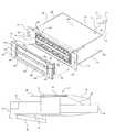
- FIG. 1illustrates a front isometric view of an interconnect cassette configured to be mated with a sensor strip assembly according to an embodiment of the present invention.
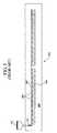
- FIG. 2illustrates a side sectional view of a portion of a patch cord formed in accordance with an embodiment of the present invention.
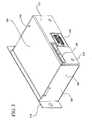
- FIG. 3illustrates a rear isometric view of an interconnect cassette according to an embodiment of the present invention.
- FIG. 4illustrates a rear isometric view of an interconnect cassette according to an alternative embodiment of the present invention.
- FIG. 5illustrates a front view of a conventional interconnect module with a flexible etched circuit mounted thereto.
- FIG. 6illustrates a front view of a conventional flexible etched circuit.
- FIG. 1illustrates a front isometric view of an interconnect cassette 300 configured to be mated with a separate and discrete sensor bezel 302 according to an embodiment of the present invention.
- the interconnect cassette 300includes a housing 304 defined by side walls 306 , a top surface 308 , a base 310 , a rear wall 312 and a jack interface 314 .
- the jack interface 314includes a plurality of receptacle jacks 370 and sensor strip pin receptacles 316 positioned to the side of the receptacle jacks 370 .
- the receptacle jacks 370each have a channel 386 along one side thereof and are configured to receive plugs 18 (as shown in FIG. 2) on patch cords 10 .
- FIG. 2illustrates a side sectional view of a portion of a patch cord 10 formed according to an embodiment of the present invention.
- the patch cord 10includes an insulated cable 14 and a plug 18 retained in a boot 22 .
- the cable 14extends to a first network component (not shown) that, by way of example only, may be a server, interconnect module or another interconnect cassette 300 .
- the cable 14contains several signal wires (not shown) that may, by way of example only, be shielded or unshielded and made of fiber optics or copper.
- a probe wire 26extends from the cable 14 to a sensor probe 30 .
- the sensor probe 30may be positioned generally parallel to a longitudinal axis of the plug 18 .
- the sensor probe 30has a probe head 98 extending outward from the boot 22 .
- a flexible prong 38extends from a front end 42 of the plug 18 rearward at an acute angle with respect to a bottom surface 36 of the plug 18 and is configured to retain the plug 18 within the interconnect cassette 300 .
- the receptacle jacks 370are arranged in two rows (A and B) each having six receptacle jacks 370 . Rows A and B of receptacles jacks 370 are stacked.
- the jack interface 314may have more or less than two rows of receptacle jacks 370 . Further, more or less than six receptacle jacks 370 may be included within each row.
- the sensor strip pin receptacles 316may be positioned above or below the rows A and B of receptacle jacks 370 depending on the location of the sensor strip pins 342 on the sensor bezel 302 .
- the interconnect cassette 300may be connected to a network connection component such as a patch panel, a wall mounted box, a floor box, or any number of other network connection structures (not shown). Mounting features, such as fastener holes 343 , are provided in the jack interface 314 to allow the interconnect cassette 300 to be mounted into a rack unit (not shown) or other such organizational and support structure.
- the interconnect cassette 300connects the receptacle jacks 370 to corresponding wires, a printed circuit board, a flexible circuit, a lead frame, or the like within the housing of the interconnect cassette 300 as opposed to directly connecting each receptacle jack 370 to a corresponding structure within another network connection.
- the wires electrically connected to the receptacle jacks 370may be bundled inside the interconnect cassette 300 and electrically connected to a signal input/output (I/O) interface 320 (as shown below with respect to FIGS. 3 and 4 ).
- the signal I/O interface 320may then be connected to a cable or other connection route (such as cable 311 ), which in turn is electrically connected to a network component or connection 313 , such as a patch panel.
- the wires from the receptacle jacks 370are bundled within the interconnect cassette 300 and subsequently routed to corresponding features in the signal I/O interface 320 within the interconnect cassette 300 , there is no need to route numerous cables and wires from the interconnect cassette 300 to the network component 313 . Rather, a single cable, such as cable 311 , may house a plurality of wires and connect the interconnect cassette 300 to the network connection 313 .
- the receptacle jacks 370may be electrically connected to a flexible or printed circuit board (not shown) within the interconnect cassette 300 that is, in turn, electrically connected to a signal input/output interface 318 located at the front or rear of the interconnect cassette 300 .
- the sensor bezel 302includes a frame 324 defined by horizontal frame members 326 formed integrally with vertical frame members 328 .
- the frame 324includes a front face 330 , a cassette interface surface 332 and a column of strip pins 342 located on one of the vertical frame members 328 .
- Portions of the cassette interface surface 332(for example, the edges of the cassette interface surface 332 ) may be beveled, notched or ribbed such that the cassette interface surface 332 engages corresponding structures in the jack interface 314 to allow the sensor bezel 302 to be snapably, latchably, removably, or otherwise securably retained by the jack interface 314 of the interconnect cassette 300 .
- the sensor bezel 302may be securably retained by the interconnect cassette 300 without the use of glue or other such adhesives.
- the strip pins 342extend outwardly from the cassette interface surface 332 and may optionally be formed on one of the horizontal frame members 326 (as a row) or on the other vertical frame member 328 . Also, optionally, strip pins 342 may be positioned on more than one of the vertical and horizontal frame member 328 and 326 (so long as they correspond to strip pin receptacles formed within the interconnect cassette 300 ).
- a sensor strip 334attached to each vertical frame member, spans longitudinally across the sensor bezel 302 in a parallel relationship with the horizontal frame members 326 .
- the sensor bezel 302may be molded with, stamped onto, or otherwise integrally formed with the frame 324 .
- the horizontal frame members 328may include slots configured to receive and retain support tabs formed as terminal ends of the sensor strip 334 . That is, the sensor strip 334 may be removable from the frame 324 .
- Two open jack cavities 336are defined between the horizontal frame members 326 and the sensor strip 334 and are configured to allow plugs 18 to pass therethrough. The jack cavities 336 allow plugs 18 of the patch cords 10 to mate with the receptacle jacks 370 as described below.
- the sensor strip 334is a flexible circuit having conducting pads or sensor contacts 340 , as commonly used as a connection sensor with interconnect modules (such as interconnect module 600 shown in FIG. 5 ).
- the sensor contacts 340are electrically connected to corresponding strip pins 342 extending outwardly from the cassette interface surface 332 .
- the sensor contacts 340may be electrically connected to the corresponding strip pins through traces (an exemplary trace, which is under the surface of the sensor strip 334 and vertical member 326 , is shown by line 341 ) that may be formed within or on the sensor strip 334 and the frame 324 .
- the sensor bezel 302is received and retained by the interconnect cassette 300 .
- the interconnect cassette 300includes features that allow the strip assembly 302 to snapably, latchably or otherwise securably mount to the jack interface 314 of the interconnect cassette 300 .
- the sensor bezel 302is mounted to the interconnect cassette 300 without the use of glue or other such adhesives.
- the sensor bezel 302may be quickly and efficiently mounted to (and removed from) the interconnect cassette 300 through snapable, latchable or other such matable engagement between the jack interface 314 and the cassette interface surface 332 .
- the strip pins 342may be securably retained by the strip pin receptacles 316 so that the strip assembly 302 is securably positioned on the jack interface 314 of the interconnect cassette 300 .
- the strip pins 342are received and retained by the strip pin receptacles 316 .
- the strip pins 342are then electrically connected to contacts (not shown) within the strip pin receptacles 316 , which are in turn electrically connected to a sensor input/output (I/O) interface 318 or insulated displacement contact (IDC) assembly 322 (as discussed below with respect to FIGS. 3 and 4) through internal traces, wires, or the like.
- the sensor I/O interface 318 or IDC assembly 322may then be in electrical communication with a sensing component 317 within or discrete from the network component 313 through a cable 315 or other such electrical path.
- the receptacle jacks 370may receive the plugs 18 of the patch cords 10 such that the flexible prongs 38 are retained in the channels 386 and biased toward the bottom surface 36 of the plugs 18 .
- the resistance of the flexible prongs 38 against the channels 386retains the plugs 18 within the receptacle jacks 370 .
- the flexible prongs 38may include a latch feature that joins a corresponding latch feature in the channel 386 .
- the sensor probes 30align with and engage corresponding sensor contacts 340 on the sensor strip 334 , thereby enabling sensor signals to pass in either direction between the plug 18 and interconnect cassette 300 .
- the sensor bezel 302may be compressibly connected to the interconnect cassette 300 .
- the sensor bezel 302may include an array of insulators and conductors. The insulators may be longer or higher than the conductors. When the array is sandwiched between the sensor bezel 302 and interconnect cassette 300 , however, the insulators may be compressed to the length or height of the conductors.
- a pin or other such element, such as the sensor probe 30 , on the plug 18 or patch cord 10contacts the sensor strip 334 if the plug 18 is fully mated into a corresponding receptacle jack 370 .
- the sensor probe 30 of the plug 18contacts a sensor contact 340 when the plug is fully mated into the receptacle jack 370 .
- an electrical circuitis formed between the plug 18 and the sensor contact 340 by virtue of the sensor probe 30 contacting the sensor contact 340 .
- the sensing component 317detects this electrical circuit as a connection between the plug 18 and its corresponding receptacle jack 370 . If, however, the plug 18 becomes dislodged from its corresponding receptacle jack 370 , the sensor probe 30 no longer contacts the sensor contact 340 . Thus, the electrical circuit is broken and the sensing component 317 senses that a connection is not present between the plug 318 and its corresponding receptacle jack 370 . The information regarding connections is relayed to a processing unit (not shown), which in turn may display connection information to an operator or overseer.
- FIG. 3illustrates a rear isometric view of an interconnect cassette 300 according to an embodiment of the present invention.
- the rear wall 312 of the interconnect cassette 300includes a sensor input/output (I/O) interface 318 and a signal input/output (I/O) interface 320 .
- the sensor I/O interface 318electrically connects to the strip pin receptacles 316 through electrical traces, cables, wires, circuit boards or the like.
- the signal I/O interface 320electrically connects to the receptacle jacks 370 through electrical traces, cables, wires, circuit boards or the like.
- the interconnect cassette 300may connect to a patch panel, or other network connection structure, such as network component 313 , through an electrical cable, such as cable 311 , that bundles a plurality of signal wires and connects them to an I/O interface on the network component 313 .
- sensor informationis relayed to a sensing component 317 through a cable 315 that connects the sensor I/O interface 318 to an interface on the sensing component 317 .
- FIG. 4illustrates a rear isometric view of an interconnect cassette 300 according to an alternative embodiment of the present invention.
- the interconnect cassette 300may include an IDC assembly 322 that may communicate with a corresponding assembly of a sensing component 317 .
- the Pepe applicationdiscloses a connector assembly having sensor contacts integrally formed with a housing of the connector assembly.
- the Pepe applicationis incorporated by reference herein in its entirety.
- the Pepe applicationdiscloses an interconnect module having a plurality of sensor contacts integrally formed thereon.
- the sensor strip 334 shown above with respect to FIG. 1may include the sensor contacts shown in the Pepe application, instead of the flexible strip 338 .
- Each contact sensor, or conducting pad of the contact sensoris electrically connected to the strip pins 342 by way of traces 341 or similar electrical paths.
- the sensor strip 334 and the sensor I/O interface 318 or the IDC assembly 322may be connected together by a printed circuit board that extends through the housing 304 of the interconnect cassette 300 .
- the printed circuit boardhas electronic traces that extend along the length thereof and that are connected to the sensor strip receptacles 316 .
- the printed circuit boardmay include signal conditioning circuits, an identification ID code unique to each receptacle jack 370 , and/or processing components that analyze and identify the type of plug inserted.
- the interconnect cassette 300 and separate sensor bezel 302confer several benefits.
- the interconnect cassette 300utilizes individual sensor contacts 340 positioned proximate each receptacle jack 370 .
- the sensor contacts 340are retained individually within the front face of the sensor bezel 302 and are connected to the sensor pins 316 through traces 341 , or the like.
- the sensor contacts 340directly connect to the sensor probes of the plugs 18 .
- the sensor contacts 340are separate and discrete from one another thereby allowing easy removal and replacement of the plugs 18 from the receptacle jacks 370 without disconnecting other plugs 18 from receptacle jacks 370 that are not being replaced/removed.
- the sensor strip 334needs to be removed, while the sensor bezel 302 and the plugs remain in place. Also, if sensor contacts 34 - are faulty, only the sensor bezel 302 needs to be replaced (as opposed to the entire interconnect cassette 300 ). Further, the sensor strip 334 of the sensor bezel 302 may be removable so that only the sensor strip 334 or individual sensor contacts 340 needs to be replaced. Finally, the sensor contacts eliminate the need for fixed lengths of cable and multiple connectors to connect sensor pads to the sensor wires, thus saving time and space.
- Embodiments of the present inventionmay be used with various applications including modular jacks.
- the present inventionmay be used to electrically or fiber optically connect components.
Landscapes
- Engineering & Computer Science (AREA)
- Computer Networks & Wireless Communication (AREA)
- Details Of Connecting Devices For Male And Female Coupling (AREA)
- Connector Housings Or Holding Contact Members (AREA)
Abstract
Description
Claims (22)
Priority Applications (12)
| Application Number | Priority Date | Filing Date | Title |
|---|---|---|---|
| US10/289,570US6626697B1 (en) | 2002-11-07 | 2002-11-07 | Network connection sensing assembly |
| DK03768701.9TDK1559277T3 (en) | 2002-11-07 | 2003-11-05 | Network Connection Detection Module |
| CN200380105340ACN100593345C (en) | 2002-11-07 | 2003-11-05 | Network connection detection module |
| PCT/US2003/035318WO2004045263A2 (en) | 2002-11-07 | 2003-11-05 | Network connection sensing module |
| JP2004551782AJP4440111B2 (en) | 2002-11-07 | 2003-11-05 | Network connection sensor assembly |
| EP03768701AEP1559277B1 (en) | 2002-11-07 | 2003-11-05 | Network connection sensing module |
| CA002504858ACA2504858A1 (en) | 2002-11-07 | 2003-11-05 | Network connection sensing module |
| DE60330891TDE60330891D1 (en) | 2002-11-07 | 2003-11-05 | NETWORK CONNECTION DETECTING MODULE |
| AU2003291309AAU2003291309B2 (en) | 2002-11-07 | 2003-11-05 | Network connection sensing module |
| ES03768701TES2336666T3 (en) | 2002-11-07 | 2003-11-05 | NETWORK CONNECTION DETECTION MODULE. |
| KR1020057008197AKR101006271B1 (en) | 2002-11-07 | 2003-11-05 | Network connection sensing assembly |
| US10/766,254US6976867B2 (en) | 2002-11-07 | 2004-01-28 | Network connection sensing assembly |
Applications Claiming Priority (1)
| Application Number | Priority Date | Filing Date | Title |
|---|---|---|---|
| US10/289,570US6626697B1 (en) | 2002-11-07 | 2002-11-07 | Network connection sensing assembly |
Related Child Applications (1)
| Application Number | Title | Priority Date | Filing Date |
|---|---|---|---|
| US10/766,254Continuation-In-PartUS6976867B2 (en) | 2002-11-07 | 2004-01-28 | Network connection sensing assembly |
Publications (1)
| Publication Number | Publication Date |
|---|---|
| US6626697B1true US6626697B1 (en) | 2003-09-30 |
Family
ID=28454471
Family Applications (1)
| Application Number | Title | Priority Date | Filing Date |
|---|---|---|---|
| US10/289,570Expired - LifetimeUS6626697B1 (en) | 2002-11-07 | 2002-11-07 | Network connection sensing assembly |
Country Status (11)
| Country | Link |
|---|---|
| US (1) | US6626697B1 (en) |
| EP (1) | EP1559277B1 (en) |
| JP (1) | JP4440111B2 (en) |
| KR (1) | KR101006271B1 (en) |
| CN (1) | CN100593345C (en) |
| AU (1) | AU2003291309B2 (en) |
| CA (1) | CA2504858A1 (en) |
| DE (1) | DE60330891D1 (en) |
| DK (1) | DK1559277T3 (en) |
| ES (1) | ES2336666T3 (en) |
| WO (1) | WO2004045263A2 (en) |
Cited By (69)
| Publication number | Priority date | Publication date | Assignee | Title |
|---|---|---|---|---|
| US20020109670A1 (en)* | 2001-02-15 | 2002-08-15 | Lumley John William | Display |
| US20050275538A1 (en)* | 2004-05-27 | 2005-12-15 | Pitney Bowes Incorporated | Security barrier for electronic circuitry |
| US6976867B2 (en)* | 2002-11-07 | 2005-12-20 | Tyco Electronics Amp Espana, S.A. | Network connection sensing assembly |
| US20060094291A1 (en)* | 2004-11-03 | 2006-05-04 | Caveney Jack E | Method and apparatus for patch panel patch cord documentation and revision |
| WO2006092553A1 (en)* | 2005-03-04 | 2006-09-08 | Tyco Electronics Amp Espana Sa | Network connection sensing assembly |
| US20060262727A1 (en)* | 2005-05-19 | 2006-11-23 | Panduit Corp. | Method and apparatus for documenting network paths |
| US20060282529A1 (en)* | 2005-06-14 | 2006-12-14 | Panduit Corp. | Method and apparatus for monitoring physical network topology information |
| AU2003291309B2 (en)* | 2002-11-07 | 2007-05-31 | Tyco Electronics Corporation | Network connection sensing module |
| US20070132503A1 (en)* | 2005-12-06 | 2007-06-14 | Panduit Corp. | Power patch panel with guided mac capability |
| US20070207666A1 (en)* | 2006-02-14 | 2007-09-06 | Panduit Corp. | Method and Apparatus for Patch Panel Patch Cord Documentation and Revision |
| US20070243725A1 (en)* | 2005-08-26 | 2007-10-18 | Panduit Corp. | Patch Field Documentation and Revision Systems |
| US20080002937A1 (en)* | 2006-06-29 | 2008-01-03 | Gordon Spisany | Patch panels with communications connectors that are rotatable about a vertical axis |
| US20080113560A1 (en)* | 2003-08-06 | 2008-05-15 | Panduit Corp. | Network Managed Device Installation and Provisioning Technique |
| US7519000B2 (en) | 2002-01-30 | 2009-04-14 | Panduit Corp. | Systems and methods for managing a network |
| US7636050B2 (en) | 2005-08-08 | 2009-12-22 | Panduit Corp. | Systems and methods for detecting a patch cord end connection |
| US7635280B1 (en)* | 2008-07-30 | 2009-12-22 | Apple Inc. | Type A USB receptacle with plug detection |
| US20100015847A1 (en)* | 2008-02-21 | 2010-01-21 | Panduit Corp. | Intelligent Inter-Connect and Cross-Connect Patching System |
| US7656903B2 (en) | 2002-01-30 | 2010-02-02 | Panduit Corp. | System and methods for documenting networks with electronic modules |
| US20100055971A1 (en)* | 2008-08-26 | 2010-03-04 | Tyco Electronics Corporation | Sensor strip for a connectivity management system |
| WO2010042586A1 (en)* | 2008-10-07 | 2010-04-15 | Molex Incorporated | Termination cap for use in wired network management system |
| US20100221951A1 (en)* | 2009-02-27 | 2010-09-02 | Tyco Electronics Corporation | Shielded cassette for a cable interconnect system |
| US20100221954A1 (en)* | 2009-02-27 | 2010-09-02 | Tyco Electronics Corporation | Cassette with locking feature |
| US20100221950A1 (en)* | 2009-02-27 | 2010-09-02 | Tyco Electronics Corporation | Shielded cassette for a cable interconnect system |
| US20100221931A1 (en)* | 2009-02-27 | 2010-09-02 | Tyco Electronics Corporation | Cassette for a cable interconnect system |
| US20100221955A1 (en)* | 2009-02-27 | 2010-09-02 | Tyco Electronics Corporation | Cassette having interchangable rear mating connectors |
| US20100221932A1 (en)* | 2009-02-27 | 2010-09-02 | Tyco Electronics Corporation | Cassette for use within a connectivity management system |
| US20100224578A1 (en)* | 2009-03-09 | 2010-09-09 | Patrick Fariello | Methods of Converting Patching System To Intelligent Patching System and Related Shelf Units |
| US7811119B2 (en) | 2005-11-18 | 2010-10-12 | Panduit Corp. | Smart cable provisioning for a patch cord management system |
| US20100296789A1 (en)* | 2009-05-22 | 2010-11-25 | Wade Womack | Telecommunications patching system with cable management system and related cable management equipment |
| US7854624B1 (en) | 2009-07-23 | 2010-12-21 | Tyco Electronics Corporation | Panel assembly for a connectivity management system |
| US20110116748A1 (en)* | 2009-10-16 | 2011-05-19 | Adc Telecommunications, Inc. | Managed connectivity in fiber optic systems and methods thereof |
| US7978845B2 (en) | 2005-09-28 | 2011-07-12 | Panduit Corp. | Powered patch panel |
| US20110228473A1 (en)* | 2010-02-12 | 2011-09-22 | Chad Anderson | Communications bladed panel systems |
| US8094019B1 (en)* | 2005-11-29 | 2012-01-10 | Vanguard Products Group, Inc. | Self-shunting security device |
| US8128428B2 (en) | 2009-02-19 | 2012-03-06 | Panduit Corp. | Cross connect patch guidance system |
| US8142221B2 (en) | 2010-04-19 | 2012-03-27 | Tyco Electronics Corporation | Plug assembly for a connectivity management system |
| US8152560B2 (en) | 2010-04-19 | 2012-04-10 | Tyco Electronics Corporation | Connectivity sensing assembly |
| US8267706B2 (en) | 2008-11-12 | 2012-09-18 | Panduit Corp. | Patch cord with insertion detection and light illumination capabilities |
| US8306935B2 (en) | 2008-12-22 | 2012-11-06 | Panduit Corp. | Physical infrastructure management system |
| US8477031B2 (en) | 2007-10-19 | 2013-07-02 | Panduit Corp. | Communication port identification system |
| US8565572B2 (en) | 2010-06-23 | 2013-10-22 | Adc Telecommunications, Inc. | Telecommunications assembly |
| WO2014021901A1 (en)* | 2012-08-01 | 2014-02-06 | Leviton Manufacturing Co., Inc. | Low profile copper and fiber optic cassettes |
| US8696369B2 (en) | 2010-09-09 | 2014-04-15 | Adc Telecommunications, Inc. | Electrical plug with main contacts and retractable secondary contacts |
| US8715012B2 (en) | 2011-04-15 | 2014-05-06 | Adc Telecommunications, Inc. | Managed electrical connectivity systems |
| CN104104541A (en)* | 2008-10-07 | 2014-10-15 | 莫列斯公司 | Termination cap for use in wired network management system |
| US8897637B2 (en) | 2009-04-22 | 2014-11-25 | Adc Gmbh | Method and arrangement for identifying at least one object |
| US8992260B2 (en) | 2009-10-16 | 2015-03-31 | Adc Telecommunications, Inc. | Managed connectivity in electrical systems and methods thereof |
| US8992261B2 (en) | 2010-10-22 | 2015-03-31 | Adc Telecommunications, Inc. | Single-piece plug nose with multiple contact sets |
| US8991690B2 (en) | 2012-11-16 | 2015-03-31 | Tyco Electronics Uk Ltd. | System and method for providing power and communication link for RFID managed connectivity using removable module |
| US9054440B2 (en) | 2009-10-19 | 2015-06-09 | Adc Telecommunications, Inc. | Managed electrical connectivity systems |
| US9064022B2 (en) | 2011-05-17 | 2015-06-23 | Adc Telecommunications, Inc. | Component identification and tracking system for telecommunication networks |
| US9093796B2 (en) | 2012-07-06 | 2015-07-28 | Adc Telecommunications, Inc. | Managed electrical connectivity systems |
| US9140859B2 (en) | 2010-02-12 | 2015-09-22 | Tyco Electronics Services Gmbh | Managed fiber connectivity systems |
| US9203198B2 (en) | 2012-09-28 | 2015-12-01 | Commscope Technologies Llc | Low profile faceplate having managed connectivity |
| US9285552B2 (en) | 2013-02-05 | 2016-03-15 | Commscope Technologies Llc | Optical assemblies with managed connectivity |
| US9379501B2 (en) | 2013-02-05 | 2016-06-28 | Commscope Technologies Llc | Optical assemblies with managed connectivity |
| US9423570B2 (en) | 2013-02-05 | 2016-08-23 | Commscope Technologies Llc | Optical assemblies with managed connectivity |
| US9470742B2 (en) | 2012-08-03 | 2016-10-18 | Commscope Technologies Llc | Managed fiber connectivity systems |
| US9500814B2 (en) | 2014-03-26 | 2016-11-22 | Commscope Technologies Llc | Optical adapter module with managed connectivity |
| US9690064B2 (en) | 2015-11-10 | 2017-06-27 | Leviton Manufacturing Co., Ltd. | Multi-gang cassette system |
| US10234648B2 (en) | 2007-08-06 | 2019-03-19 | Commscope Technologies Llc | Fiber optic enclosure with internal cable spool |
| US10295773B2 (en) | 2017-03-29 | 2019-05-21 | Leviton Manufacturing Co., Inc. | Segregated fiber in a splice cassette |
| US10371914B2 (en) | 2011-06-24 | 2019-08-06 | Commscope Technologies Llc | Fiber termination enclosure with modular plate assemblies |
| US10418764B2 (en) | 2014-08-06 | 2019-09-17 | Molex, Llc | Patch panel frame for circuit board module |
| US20200026008A1 (en)* | 2013-08-21 | 2020-01-23 | Mertek Industries, Llc | Traceable networking cables with remote-released connectors |
| US10545305B2 (en) | 2012-12-19 | 2020-01-28 | CommScope Connectivity Belgium BVBA | Distribution device with incrementally added splitters |
| US10627592B2 (en) | 2007-05-07 | 2020-04-21 | Commscope Technologies Llc | Fiber optic assembly with cable spool |
| US11689247B2 (en) | 2019-01-16 | 2023-06-27 | Mertek Industries, Llc | Patch cord including wireless components |
| US12300943B2 (en) | 2019-09-30 | 2025-05-13 | Mertek Industries, Llc | Patch panel traceable networking system |
Families Citing this family (9)
| Publication number | Priority date | Publication date | Assignee | Title |
|---|---|---|---|---|
| US7560175B2 (en) | 1999-12-31 | 2009-07-14 | Lg Chem, Ltd. | Electroluminescent devices with low work function anode |
| WO2004082078A1 (en)* | 2003-03-11 | 2004-09-23 | Tyco Electronics Amp Espana S.A. | Network connection sensing assembly |
| US7311539B2 (en)* | 2005-04-29 | 2007-12-25 | Tyco Electronics Corporation | Duplex plug adapter module |
| CN101163169B (en)* | 2006-10-12 | 2010-07-28 | 智邦科技股份有限公司 | Test device capable of testing network equipment |
| KR100900796B1 (en) | 2007-09-13 | 2009-06-02 | 아주대학교산학협력단 | Sensor node |
| KR101109145B1 (en)* | 2010-01-21 | 2012-02-27 | 주식회사웨이브시스컴 | patch pannel for connecting patch cord |
| KR102012054B1 (en)* | 2013-04-19 | 2019-08-19 | 엘에스전선 주식회사 | Patch Cord, Patch Panel And Management System Having The Same |
| US9287663B1 (en)* | 2014-08-26 | 2016-03-15 | Lg Chem, Ltd. | Electrical connector and method of electrically coupling first and second electrical terminals of first and second battery cells to one another |
| JP6627620B2 (en)* | 2016-04-05 | 2020-01-08 | 株式会社オートネットワーク技術研究所 | Connectors, connection status detection systems, and terminals |
Citations (7)
| Publication number | Priority date | Publication date | Assignee | Title |
|---|---|---|---|---|
| US4237386A (en)* | 1976-06-29 | 1980-12-02 | E-Comm Australia Pty. Ltd. | Plug-in module for touch control switching |
| US5178554A (en)* | 1990-10-26 | 1993-01-12 | The Siemon Company | Modular jack patching device |
| US5347095A (en)* | 1991-07-05 | 1994-09-13 | Abraham Zeder | Electrical receptacle for use with annunciator apparatus for monitoring electrical connections |
| US5434558A (en)* | 1991-07-05 | 1995-07-18 | Zeder; Abraham | Annunciator apparatus for monitoring electrical connections |
| US5483467A (en)* | 1992-06-10 | 1996-01-09 | Rit Technologies, Ltd. | Patching panel scanner |
| US5870626A (en)* | 1994-04-08 | 1999-02-09 | Lebeau; Luc | Device for the computer linking of apparatuses with heterogeneous communication systems, and key pertaining to such a device |
| WO2000060475A1 (en) | 1999-04-06 | 2000-10-12 | Cablesoft, Inc. | A system for monitoring connection pattern of data ports |
Family Cites Families (6)
| Publication number | Priority date | Publication date | Assignee | Title |
|---|---|---|---|---|
| GB2374941B (en)* | 1999-02-10 | 2003-05-07 | Lucent Technologies Inc | Method and device for detecting the presence of a patch cord connector in a te lecommunications patch system |
| US6234830B1 (en) | 1999-02-10 | 2001-05-22 | Avaya Technology Corp. | Tracing interface module for patch cords in a telecommunications system |
| US6424710B1 (en)* | 1999-02-10 | 2002-07-23 | Avaya Technology Corp. | Method and device for detecting the presence of a patch cord connector in a telecommunications patch system using passive detection sensors |
| US6222908B1 (en)* | 1999-09-23 | 2001-04-24 | Avaya Technology Corp. | Method and device for identifying a specific patch cord connector as it is introduced into, or removed from, a telecommunications patch system |
| US6976867B2 (en)* | 2002-11-07 | 2005-12-20 | Tyco Electronics Amp Espana, S.A. | Network connection sensing assembly |
| US6626697B1 (en)* | 2002-11-07 | 2003-09-30 | Tyco Electronics Corp. | Network connection sensing assembly |
- 2002
- 2002-11-07USUS10/289,570patent/US6626697B1/ennot_activeExpired - Lifetime
- 2003
- 2003-11-05EPEP03768701Apatent/EP1559277B1/ennot_activeExpired - Lifetime
- 2003-11-05KRKR1020057008197Apatent/KR101006271B1/ennot_activeExpired - Fee Related
- 2003-11-05DEDE60330891Tpatent/DE60330891D1/ennot_activeExpired - Lifetime
- 2003-11-05DKDK03768701.9Tpatent/DK1559277T3/enactive
- 2003-11-05JPJP2004551782Apatent/JP4440111B2/ennot_activeExpired - Fee Related
- 2003-11-05WOPCT/US2003/035318patent/WO2004045263A2/enactiveIP Right Grant
- 2003-11-05AUAU2003291309Apatent/AU2003291309B2/ennot_activeCeased
- 2003-11-05CNCN200380105340Apatent/CN100593345C/ennot_activeExpired - Fee Related
- 2003-11-05CACA002504858Apatent/CA2504858A1/ennot_activeAbandoned
- 2003-11-05ESES03768701Tpatent/ES2336666T3/ennot_activeExpired - Lifetime
Patent Citations (7)
| Publication number | Priority date | Publication date | Assignee | Title |
|---|---|---|---|---|
| US4237386A (en)* | 1976-06-29 | 1980-12-02 | E-Comm Australia Pty. Ltd. | Plug-in module for touch control switching |
| US5178554A (en)* | 1990-10-26 | 1993-01-12 | The Siemon Company | Modular jack patching device |
| US5347095A (en)* | 1991-07-05 | 1994-09-13 | Abraham Zeder | Electrical receptacle for use with annunciator apparatus for monitoring electrical connections |
| US5434558A (en)* | 1991-07-05 | 1995-07-18 | Zeder; Abraham | Annunciator apparatus for monitoring electrical connections |
| US5483467A (en)* | 1992-06-10 | 1996-01-09 | Rit Technologies, Ltd. | Patching panel scanner |
| US5870626A (en)* | 1994-04-08 | 1999-02-09 | Lebeau; Luc | Device for the computer linking of apparatuses with heterogeneous communication systems, and key pertaining to such a device |
| WO2000060475A1 (en) | 1999-04-06 | 2000-10-12 | Cablesoft, Inc. | A system for monitoring connection pattern of data ports |
Cited By (218)
| Publication number | Priority date | Publication date | Assignee | Title |
|---|---|---|---|---|
| US6784860B2 (en)* | 2001-02-15 | 2004-08-31 | Hewlett-Packard Development Company, L.P. | Display |
| US20020109670A1 (en)* | 2001-02-15 | 2002-08-15 | Lumley John William | Display |
| US7656903B2 (en) | 2002-01-30 | 2010-02-02 | Panduit Corp. | System and methods for documenting networks with electronic modules |
| US7519000B2 (en) | 2002-01-30 | 2009-04-14 | Panduit Corp. | Systems and methods for managing a network |
| AU2003291309B2 (en)* | 2002-11-07 | 2007-05-31 | Tyco Electronics Corporation | Network connection sensing module |
| US6976867B2 (en)* | 2002-11-07 | 2005-12-20 | Tyco Electronics Amp Espana, S.A. | Network connection sensing assembly |
| US8325770B2 (en) | 2003-08-06 | 2012-12-04 | Panduit Corp. | Network managed device installation and provisioning technique |
| US20080113560A1 (en)* | 2003-08-06 | 2008-05-15 | Panduit Corp. | Network Managed Device Installation and Provisioning Technique |
| US7247791B2 (en)* | 2004-05-27 | 2007-07-24 | Pitney Bowes Inc. | Security barrier for electronic circuitry |
| US20050275538A1 (en)* | 2004-05-27 | 2005-12-15 | Pitney Bowes Incorporated | Security barrier for electronic circuitry |
| US7297018B2 (en) | 2004-11-03 | 2007-11-20 | Panduit Corp. | Method and apparatus for patch panel patch cord documentation and revision |
| US20060094291A1 (en)* | 2004-11-03 | 2006-05-04 | Caveney Jack E | Method and apparatus for patch panel patch cord documentation and revision |
| US20080045075A1 (en)* | 2004-11-03 | 2008-02-21 | Panduit Corp. | Method and Apparatus for Patch Panel Patch Cord Documentation and Revision |
| US7517243B2 (en) | 2004-11-03 | 2009-04-14 | Panduit Corp. | Method and apparatus for patch panel patch cord documentation and revision |
| WO2006092553A1 (en)* | 2005-03-04 | 2006-09-08 | Tyco Electronics Amp Espana Sa | Network connection sensing assembly |
| RU2388173C2 (en)* | 2005-03-04 | 2010-04-27 | Тайко Электроникс Эй-Эм-Пи Эспанья С.А. | Network connection registration unit |
| CN101133654B (en)* | 2005-03-04 | 2011-01-26 | 安普泰科电子西班牙股份有限公司 | Network Connectivity Sensing Components |
| AU2006219761B2 (en)* | 2005-03-04 | 2009-12-10 | Tyco Electronics Amp Espana Sa | Network connection sensing assembly |
| US7591667B2 (en) | 2005-03-04 | 2009-09-22 | Tyco Electronics Amp Espana Sa | Network connection sensing assembly |
| US20090053923A1 (en)* | 2005-03-04 | 2009-02-26 | Tyco Electronics Amp Espana Sa | Network Connection Sensing Assembly |
| US20060262727A1 (en)* | 2005-05-19 | 2006-11-23 | Panduit Corp. | Method and apparatus for documenting network paths |
| US7613124B2 (en) | 2005-05-19 | 2009-11-03 | Panduit Corp. | Method and apparatus for documenting network paths |
| US7756047B2 (en) | 2005-05-19 | 2010-07-13 | Panduit Corp. | Method and apparatus for documenting network paths |
| US20060282529A1 (en)* | 2005-06-14 | 2006-12-14 | Panduit Corp. | Method and apparatus for monitoring physical network topology information |
| US8482421B2 (en) | 2005-08-08 | 2013-07-09 | Panduit Corp. | Systems and methods for detecting a patch cord end connection |
| US7636050B2 (en) | 2005-08-08 | 2009-12-22 | Panduit Corp. | Systems and methods for detecting a patch cord end connection |
| US7969320B2 (en) | 2005-08-08 | 2011-06-28 | Panduit Corp. | Systems and methods for detecting a patch cord end connection |
| US7563102B2 (en) | 2005-08-26 | 2009-07-21 | Panduit Corp. | Patch field documentation and revision systems |
| US9049499B2 (en) | 2005-08-26 | 2015-06-02 | Panduit Corp. | Patch field documentation and revision systems |
| US20070243725A1 (en)* | 2005-08-26 | 2007-10-18 | Panduit Corp. | Patch Field Documentation and Revision Systems |
| US7978845B2 (en) | 2005-09-28 | 2011-07-12 | Panduit Corp. | Powered patch panel |
| US7811119B2 (en) | 2005-11-18 | 2010-10-12 | Panduit Corp. | Smart cable provisioning for a patch cord management system |
| US8094019B1 (en)* | 2005-11-29 | 2012-01-10 | Vanguard Products Group, Inc. | Self-shunting security device |
| US20070132503A1 (en)* | 2005-12-06 | 2007-06-14 | Panduit Corp. | Power patch panel with guided mac capability |
| US7768418B2 (en) | 2005-12-06 | 2010-08-03 | Panduit Corp. | Power patch panel with guided MAC capability |
| US20070207666A1 (en)* | 2006-02-14 | 2007-09-06 | Panduit Corp. | Method and Apparatus for Patch Panel Patch Cord Documentation and Revision |
| US7488206B2 (en) | 2006-02-14 | 2009-02-10 | Panduit Corp. | Method and apparatus for patch panel patch cord documentation and revision |
| US7534137B2 (en) | 2006-02-14 | 2009-05-19 | Panduit Corp. | Method and apparatus for patch panel patch cord documentation and revision |
| US20080002937A1 (en)* | 2006-06-29 | 2008-01-03 | Gordon Spisany | Patch panels with communications connectors that are rotatable about a vertical axis |
| AU2007270026B2 (en)* | 2006-06-29 | 2010-05-27 | Commscope, Inc. Of North Carolina | Patch panels with communications connectors that are rotatable about a vertical axis |
| US7343078B2 (en)* | 2006-06-29 | 2008-03-11 | Commscope Solutions Properties, Llc | Patch panels with communications connectors that are rotatable about a vertical axis |
| US7529458B2 (en)* | 2006-06-29 | 2009-05-05 | Commscope Solutions Properties, Llc | Patch panels with communications connectors that are rotatable about a vertical axis |
| US11009671B2 (en) | 2007-05-07 | 2021-05-18 | Commscope Technologies Llc | Fiber optic assembly with cable storage arrangement |
| US10788642B2 (en) | 2007-05-07 | 2020-09-29 | Commscope Technologies Llc | Fiber optic assembly with cable storage arrangement |
| US10627592B2 (en) | 2007-05-07 | 2020-04-21 | Commscope Technologies Llc | Fiber optic assembly with cable spool |
| US12235506B2 (en) | 2007-05-07 | 2025-02-25 | Commscope Technologies Llc | Fiber optic enclosure with external cable spool |
| US12253734B2 (en) | 2007-08-06 | 2025-03-18 | Commscope Technologies Llc | Fiber optic enclosure with internal cable spool |
| US10712518B2 (en) | 2007-08-06 | 2020-07-14 | Commscope Technologies Llc | Fiber optic enclosure with lockable internal cable spool |
| US10606017B2 (en) | 2007-08-06 | 2020-03-31 | Commscope Technologies Llc | Fiber optic payout assembly including cable spool |
| US10606015B2 (en) | 2007-08-06 | 2020-03-31 | Commscope Technologies Llc | Fiber optic payout assembly including cable spool |
| US10247897B2 (en) | 2007-08-06 | 2019-04-02 | Commscope Technologies Llc | Fiber optic enclosure with internal cable spool |
| US10495836B2 (en) | 2007-08-06 | 2019-12-03 | Commscope Technologies Llc | Fiber optic payout assembly including cable spool |
| US10234648B2 (en) | 2007-08-06 | 2019-03-19 | Commscope Technologies Llc | Fiber optic enclosure with internal cable spool |
| US12019301B2 (en) | 2007-08-06 | 2024-06-25 | Commscope Technologies Llc | Fiber optic enclosure with internal cable spool |
| US10895705B2 (en) | 2007-08-06 | 2021-01-19 | Commscope Technologies Llc | Fiber optic enclosure with internal cable spool |
| US11573390B2 (en) | 2007-08-06 | 2023-02-07 | Commscope Technologies Llc | Fiber optic enclosure with internal cable spool |
| US10996417B2 (en) | 2007-08-06 | 2021-05-04 | Commscope Technologies Llc | Fiber optic enclosure with internal cable spool and movable cover |
| US10996418B2 (en) | 2007-08-06 | 2021-05-04 | Commscope Technologies Llc | Connecting subscribers to a fiber optic network using a cable spool |
| US8477031B2 (en) | 2007-10-19 | 2013-07-02 | Panduit Corp. | Communication port identification system |
| US20110195598A1 (en)* | 2007-12-11 | 2011-08-11 | Panella Augusto P | Termination Cap For Use In Wired Network Management System |
| US9866458B2 (en) | 2008-02-21 | 2018-01-09 | Panduit Corp. | Intelligent inter-connect and cross-connect patching system |
| US7938700B2 (en) | 2008-02-21 | 2011-05-10 | Panduit Corp. | Intelligent inter-connect and cross-connect patching system |
| US8715001B2 (en) | 2008-02-21 | 2014-05-06 | Panduit Corp. | Intelligent inter-connect and cross-connect patching system |
| US20100015847A1 (en)* | 2008-02-21 | 2010-01-21 | Panduit Corp. | Intelligent Inter-Connect and Cross-Connect Patching System |
| US8419465B2 (en) | 2008-02-21 | 2013-04-16 | Panduit Corp. | Intelligent inter-connect and cross-connect patching system |
| US8246397B2 (en) | 2008-02-21 | 2012-08-21 | Panduit Corp. | Intelligent inter-connect and cross-connect patching system |
| US7635280B1 (en)* | 2008-07-30 | 2009-12-22 | Apple Inc. | Type A USB receptacle with plug detection |
| US20100057946A1 (en)* | 2008-07-30 | 2010-03-04 | Apple Inc. | Type a usb receptacle with plug detection |
| US8013616B2 (en) | 2008-07-30 | 2011-09-06 | Apple Inc. | Type A USB receptacle with plug detection |
| US7880475B2 (en) | 2008-07-30 | 2011-02-01 | Apple Inc. | Type A USB receptacle with plug detection |
| US20110093624A1 (en)* | 2008-07-30 | 2011-04-21 | Apple Inc. | Type a usb receptacle with plug detection |
| US20100055971A1 (en)* | 2008-08-26 | 2010-03-04 | Tyco Electronics Corporation | Sensor strip for a connectivity management system |
| WO2010027399A1 (en)* | 2008-08-26 | 2010-03-11 | Tyco Electronics Corporation | Sensor strip for a connectivity management system |
| US7695309B2 (en) | 2008-08-26 | 2010-04-13 | Tyco Electronics Corporation | Sensor strip for a connectivity management system |
| CN102210061B (en)* | 2008-10-07 | 2015-08-05 | 莫列斯公司 | End caps for use in wired network management systems |
| WO2010042586A1 (en)* | 2008-10-07 | 2010-04-15 | Molex Incorporated | Termination cap for use in wired network management system |
| US8376787B2 (en)* | 2008-10-07 | 2013-02-19 | Molex Incorporated | Termination cap for use in wired network management system |
| CN102210061A (en)* | 2008-10-07 | 2011-10-05 | 莫列斯公司 | End caps for use in wired network management systems |
| CN104104541A (en)* | 2008-10-07 | 2014-10-15 | 莫列斯公司 | Termination cap for use in wired network management system |
| CN104104541B (en)* | 2008-10-07 | 2017-10-10 | 莫列斯公司 | For the end cap in wired network management system |
| US8267706B2 (en) | 2008-11-12 | 2012-09-18 | Panduit Corp. | Patch cord with insertion detection and light illumination capabilities |
| US8414319B2 (en) | 2008-11-12 | 2013-04-09 | Panduit Corp. | Patch cord with insertion detection and light illumination capabilities |
| US8708724B2 (en) | 2008-11-12 | 2014-04-29 | Panduit Corp. | Patch cord insertion detection and light illumination capabilities |
| US9026486B2 (en) | 2008-12-22 | 2015-05-05 | Panduit Corp. | Physical infrastructure management system |
| US8306935B2 (en) | 2008-12-22 | 2012-11-06 | Panduit Corp. | Physical infrastructure management system |
| US8719205B2 (en) | 2008-12-22 | 2014-05-06 | Panduit Corp. | Physical infrastructure management system |
| US10516580B2 (en) | 2008-12-22 | 2019-12-24 | Panduit Corp. | Physical infrastructure management system |
| US8382511B2 (en) | 2009-02-19 | 2013-02-26 | Panduit Corp. | Cross connect patch guidance system |
| US8128428B2 (en) | 2009-02-19 | 2012-03-06 | Panduit Corp. | Cross connect patch guidance system |
| US8721360B2 (en) | 2009-02-19 | 2014-05-13 | Panduit Corp. | Methods for patch cord guidance |
| US20100221950A1 (en)* | 2009-02-27 | 2010-09-02 | Tyco Electronics Corporation | Shielded cassette for a cable interconnect system |
| US7909619B2 (en) | 2009-02-27 | 2011-03-22 | Tyco Electronics Corporation | Cassette with locking feature |
| US7878824B2 (en) | 2009-02-27 | 2011-02-01 | Tyco Electronics Corporation | Shielded cassette for a cable interconnect system |
| US20100221951A1 (en)* | 2009-02-27 | 2010-09-02 | Tyco Electronics Corporation | Shielded cassette for a cable interconnect system |
| US20100221932A1 (en)* | 2009-02-27 | 2010-09-02 | Tyco Electronics Corporation | Cassette for use within a connectivity management system |
| US20100221954A1 (en)* | 2009-02-27 | 2010-09-02 | Tyco Electronics Corporation | Cassette with locking feature |
| US20100221931A1 (en)* | 2009-02-27 | 2010-09-02 | Tyco Electronics Corporation | Cassette for a cable interconnect system |
| US20100221955A1 (en)* | 2009-02-27 | 2010-09-02 | Tyco Electronics Corporation | Cassette having interchangable rear mating connectors |
| US7914324B2 (en)* | 2009-02-27 | 2011-03-29 | Tyco Electronics Corporation | Cassette for use within a connectivity management system |
| US7909622B2 (en) | 2009-02-27 | 2011-03-22 | Tyco Electronics Corporation | Shielded cassette for a cable interconnect system |
| US7909643B2 (en) | 2009-02-27 | 2011-03-22 | Tyco Electronics Corporation | Cassette for a cable interconnect system |
| US20100224578A1 (en)* | 2009-03-09 | 2010-09-09 | Patrick Fariello | Methods of Converting Patching System To Intelligent Patching System and Related Shelf Units |
| US8753142B2 (en)* | 2009-03-09 | 2014-06-17 | Commscope, Inc. Of North Carolina | Methods of converting patching system to intelligent patching system and related shelf units |
| US8897637B2 (en) | 2009-04-22 | 2014-11-25 | Adc Gmbh | Method and arrangement for identifying at least one object |
| US20100296789A1 (en)* | 2009-05-22 | 2010-11-25 | Wade Womack | Telecommunications patching system with cable management system and related cable management equipment |
| US8744228B2 (en) | 2009-05-22 | 2014-06-03 | Commscope, Inc. Of North Carolina | Telecommunications patching system with cable management system and related cable management equipment |
| US7854624B1 (en) | 2009-07-23 | 2010-12-21 | Tyco Electronics Corporation | Panel assembly for a connectivity management system |
| US8596882B2 (en) | 2009-10-16 | 2013-12-03 | Adc Telecommunications, Inc. | Managed connectivity in fiber optic systems and methods thereof |
| US12235494B2 (en) | 2009-10-16 | 2025-02-25 | Commscope Technologies Llc | Managed connectivity in fiber optic systems and methods thereof |
| US11630269B2 (en) | 2009-10-16 | 2023-04-18 | Commscope Technologies Llc | Managed connectivity in fiber optic systems and methods thereof |
| US9967983B2 (en) | 2009-10-16 | 2018-05-08 | Commscope Technologies Llc | Managed connectivity in electrical systems and methods thereof |
| US8992260B2 (en) | 2009-10-16 | 2015-03-31 | Adc Telecommunications, Inc. | Managed connectivity in electrical systems and methods thereof |
| US9810860B2 (en) | 2009-10-16 | 2017-11-07 | Commscope Technologies Llc | Managed connectivity in fiber optic systems and methods thereof |
| US10678001B2 (en) | 2009-10-16 | 2020-06-09 | Commscope Technologies Llc | Managed connectivity in fiber optic systems and methods thereof |
| US9769939B2 (en) | 2009-10-16 | 2017-09-19 | Commscope Technologies Llc | Managed connectivity in electrical systems and methods thereof |
| US9176294B2 (en) | 2009-10-16 | 2015-11-03 | Tyco Electronics Services Gmbh | Managed connectivity in fiber optic systems and methods thereof |
| US10470320B2 (en) | 2009-10-16 | 2019-11-05 | Commscope Technologies Llc | Managed connectivity in electrical systems and methods thereof |
| US20110116748A1 (en)* | 2009-10-16 | 2011-05-19 | Adc Telecommunications, Inc. | Managed connectivity in fiber optic systems and methods thereof |
| US11191173B2 (en) | 2009-10-16 | 2021-11-30 | Commscope Technologies Llc | Managed connectivity in electrical systems and methods thereof |
| US11231555B2 (en) | 2009-10-16 | 2022-01-25 | Commscope Technologies Llc | Managed connectivity in fiber optic systems and methods thereof |
| US9401552B2 (en) | 2009-10-16 | 2016-07-26 | Commscope Technologies Llc | Managed connectivity in electrical systems and methods thereof |
| US10958024B2 (en) | 2009-10-19 | 2021-03-23 | Commscope Technologies Llc | Managed electrical connectivity systems |
| US9595797B2 (en) | 2009-10-19 | 2017-03-14 | Commscope Technologies Llc | Managed electrical connectivity systems |
| US10574008B2 (en)* | 2009-10-19 | 2020-02-25 | Commscope Technologies Llc | Managed electrical connectivity systems |
| US9054440B2 (en) | 2009-10-19 | 2015-06-09 | Adc Telecommunications, Inc. | Managed electrical connectivity systems |
| US10177514B2 (en) | 2009-10-19 | 2019-01-08 | Commscope Technologies Llc | Managed electrical connectivity systems |
| US11862912B2 (en) | 2009-10-19 | 2024-01-02 | Commscope Technologies Llc | Managed electrical connectivity systems |
| US11469560B2 (en) | 2009-10-19 | 2022-10-11 | Commscope Technologies Llc | Managed electrical connectivity systems |
| US9140859B2 (en) | 2010-02-12 | 2015-09-22 | Tyco Electronics Services Gmbh | Managed fiber connectivity systems |
| US9417399B2 (en) | 2010-02-12 | 2016-08-16 | Commscope Technologies Llc | Managed fiber connectivity systems |
| US8923013B2 (en) | 2010-02-12 | 2014-12-30 | Adc Telecommunications, Inc. | Communications bladed panel systems |
| US9223105B2 (en) | 2010-02-12 | 2015-12-29 | Commscope Technologies Llc | Communications bladed panel systems |
| US9213363B2 (en) | 2010-02-12 | 2015-12-15 | Tyco Electronics Services Gmbh | Communications bladed panel systems |
| US9532482B2 (en) | 2010-02-12 | 2016-12-27 | Commscope Technologies Llc | Communications bladed panel systems |
| US9532481B2 (en) | 2010-02-12 | 2016-12-27 | Commscope Technologies Llc | Communications bladed panel systems |
| US9549484B2 (en) | 2010-02-12 | 2017-01-17 | Commscope Technologies Llc | Communications bladed panel systems |
| US8934253B2 (en) | 2010-02-12 | 2015-01-13 | Adc Telecommunications, Inc. | Communications bladed panel systems |
| US9632255B2 (en) | 2010-02-12 | 2017-04-25 | Commscope Technologies Llc | Managed fiber connectivity systems |
| US8934252B2 (en) | 2010-02-12 | 2015-01-13 | Adc Telecommunications, Inc. | Communications bladed panel systems |
| US9684134B2 (en) | 2010-02-12 | 2017-06-20 | Commscope Technologies Llc | Managed fiber connectivity systems |
| US20110228473A1 (en)* | 2010-02-12 | 2011-09-22 | Chad Anderson | Communications bladed panel systems |
| US10123444B2 (en) | 2010-02-12 | 2018-11-06 | Commscope Technologies Llc | Communications bladed panel systems |
| US9198320B2 (en) | 2010-02-12 | 2015-11-24 | Tyco Electronics Services Gmbh | Communications bladed panel systems |
| US10473864B2 (en)* | 2010-02-12 | 2019-11-12 | Commscope Technologies Llc | Managed fiber connectivity systems |
| US10983285B2 (en) | 2010-02-12 | 2021-04-20 | Commscope Technologies Llc | Managed fiber connectivity systems |
| US9020319B2 (en) | 2010-02-12 | 2015-04-28 | Adc Telecommunications, Inc. | Communications bladed panel systems |
| US9804337B2 (en) | 2010-02-12 | 2017-10-31 | Commscope Technologies Llc | Managed fiber connectivity systems |
| US9265172B2 (en) | 2010-02-12 | 2016-02-16 | Commscope Technologies Llc | Communications bladed panel systems |
| US11899246B2 (en) | 2010-02-12 | 2024-02-13 | Commscope Technologies Llc | Managed fiber connectivity systems |
| US10088636B2 (en) | 2010-02-12 | 2018-10-02 | Commscope Technologies Llc | Managed fiber connectivity systems |
| US12306444B2 (en) | 2010-02-12 | 2025-05-20 | Commscope Technologies Llc | Managed fiber connectivity systems |
| US11378755B2 (en) | 2010-02-12 | 2022-07-05 | Commscope Technologies Llc | Managed fiber connectivity systems |
| US8142221B2 (en) | 2010-04-19 | 2012-03-27 | Tyco Electronics Corporation | Plug assembly for a connectivity management system |
| US8152560B2 (en) | 2010-04-19 | 2012-04-10 | Tyco Electronics Corporation | Connectivity sensing assembly |
| US8565572B2 (en) | 2010-06-23 | 2013-10-22 | Adc Telecommunications, Inc. | Telecommunications assembly |
| US9678296B2 (en) | 2010-06-23 | 2017-06-13 | Commscope Technologies Llc | Telecommunications assembly |
| US11789226B2 (en) | 2010-06-23 | 2023-10-17 | Commscope Technologies Llc | Telecommunications assembly |
| US10884211B2 (en) | 2010-06-23 | 2021-01-05 | Commscope Technologies Llc | Telecommunications assembly |
| US9341802B2 (en) | 2010-06-23 | 2016-05-17 | Commscope Technologies Llc | Telecommunications assembly |
| US9995898B2 (en) | 2010-06-23 | 2018-06-12 | Commscope Technologies Llc | Telecommunications assembly |
| US10627593B2 (en) | 2010-06-23 | 2020-04-21 | Commscope Technologies Llc | Telecommunications assembly |
| US10268014B2 (en) | 2010-06-23 | 2019-04-23 | Commscope Technologies Llc | Telecommunications assembly |
| US12235504B2 (en) | 2010-06-23 | 2025-02-25 | Commscope Technologies Llc | Telecommunications assembly |
| US11402595B2 (en) | 2010-06-23 | 2022-08-02 | Commscope Technologies Llc | Telecommunications assembly |
| US10126516B1 (en) | 2010-06-23 | 2018-11-13 | Commscope Technologies Llc | Telecommunications assembly |
| US9170392B2 (en) | 2010-06-23 | 2015-10-27 | Tyco Electronics Services Gmbh | Telecommunications assembly |
| US8696369B2 (en) | 2010-09-09 | 2014-04-15 | Adc Telecommunications, Inc. | Electrical plug with main contacts and retractable secondary contacts |
| US8992261B2 (en) | 2010-10-22 | 2015-03-31 | Adc Telecommunications, Inc. | Single-piece plug nose with multiple contact sets |
| US8944856B2 (en) | 2011-04-15 | 2015-02-03 | Adc Telecommunications, Inc. | Managed electrical connectivity systems |
| US9147983B2 (en) | 2011-04-15 | 2015-09-29 | Adc Telecommunications, Inc. | Managed electrical connectivity systems |
| US9502843B2 (en) | 2011-04-15 | 2016-11-22 | Commscope Technologies Llc | Managed electrical connectivity systems |
| US8715012B2 (en) | 2011-04-15 | 2014-05-06 | Adc Telecommunications, Inc. | Managed electrical connectivity systems |
| US9064022B2 (en) | 2011-05-17 | 2015-06-23 | Adc Telecommunications, Inc. | Component identification and tracking system for telecommunication networks |
| US10371914B2 (en) | 2011-06-24 | 2019-08-06 | Commscope Technologies Llc | Fiber termination enclosure with modular plate assemblies |
| US11624884B2 (en) | 2011-06-24 | 2023-04-11 | Commscope Technologies Llc | Fiber termination enclosure with modular plate assemblies |
| US10935744B2 (en) | 2011-06-24 | 2021-03-02 | Commscope Technologies Llc | Fiber termination enclosure with modular plate assemblies |
| US10502916B2 (en) | 2011-06-24 | 2019-12-10 | Commscope Technologies Llc | Fiber termination enclosure with modular plate assemblies |
| US11327262B2 (en) | 2011-06-24 | 2022-05-10 | Commscope Technologies Llc | Fiber termination enclosure with modular plate assemblies |
| US11988883B2 (en) | 2011-06-24 | 2024-05-21 | Commscope Technologies Llc | Fiber termination enclosure with modular plate assemblies |
| US9093796B2 (en) | 2012-07-06 | 2015-07-28 | Adc Telecommunications, Inc. | Managed electrical connectivity systems |
| US9437990B2 (en) | 2012-07-06 | 2016-09-06 | Commscope Technologies Llc | Managed electrical connectivity systems |
| US8958680B2 (en) | 2012-08-01 | 2015-02-17 | Leviton Manufacturing Co., Ltd. | Low profile copper and fiber optic cassettes |
| US9077126B2 (en) | 2012-08-01 | 2015-07-07 | Leviton Manufacturing Co., Inc. | Low profile copper and fiber optic cassettes |
| US8781284B2 (en) | 2012-08-01 | 2014-07-15 | Leviton Manufacturing Co., Inc. | Low profile copper and fiber optic cassettes |
| US9236691B2 (en) | 2012-08-01 | 2016-01-12 | Leviton Manufacturing Co., Inc. | Low profile copper and fiber optic cassettes |
| WO2014021901A1 (en)* | 2012-08-01 | 2014-02-06 | Leviton Manufacturing Co., Inc. | Low profile copper and fiber optic cassettes |
| US9470742B2 (en) | 2012-08-03 | 2016-10-18 | Commscope Technologies Llc | Managed fiber connectivity systems |
| US9203198B2 (en) | 2012-09-28 | 2015-12-01 | Commscope Technologies Llc | Low profile faceplate having managed connectivity |
| US9525255B2 (en) | 2012-09-28 | 2016-12-20 | Commscope Technologies Llc | Low profile faceplate having managed connectivity |
| US8991690B2 (en) | 2012-11-16 | 2015-03-31 | Tyco Electronics Uk Ltd. | System and method for providing power and communication link for RFID managed connectivity using removable module |
| US10205287B2 (en) | 2012-11-16 | 2019-02-12 | Commscope Connectivity Uk Limited | Method and system for performing a single localized read transaction in which multiple RFID tags are read |
| US9130318B2 (en) | 2012-11-16 | 2015-09-08 | Tyco Electronics Uk Ltd. | Localized reading of RFID tags located on multiple sides of a port from a single side using RFID coupling circuit and portable RFID reader |
| US9722367B2 (en) | 2012-11-16 | 2017-08-01 | Commscope Connectivity Uk Limited | Method and system for performing a single localized read transaction in which multiple RFID tags are read |
| US10545305B2 (en) | 2012-12-19 | 2020-01-28 | CommScope Connectivity Belgium BVBA | Distribution device with incrementally added splitters |
| US11327248B2 (en) | 2013-02-05 | 2022-05-10 | Commscope Technologies Llc | Optical assemblies with managed connectivity |
| US9778424B2 (en) | 2013-02-05 | 2017-10-03 | Commscope Technologies Llc | Optical assemblies with managed connectivity |
| US10571641B2 (en) | 2013-02-05 | 2020-02-25 | Commscope Technologies Llc | Optical assemblies with managed connectivity |
| US11143833B2 (en) | 2013-02-05 | 2021-10-12 | Commscope Technologies Llc | Optical assemblies with managed connectivity |
| US12235505B2 (en) | 2013-02-05 | 2025-02-25 | Commscope Technologies Llc | Fiber optic cassette arrangement |
| US9423570B2 (en) | 2013-02-05 | 2016-08-23 | Commscope Technologies Llc | Optical assemblies with managed connectivity |
| US9379501B2 (en) | 2013-02-05 | 2016-06-28 | Commscope Technologies Llc | Optical assemblies with managed connectivity |
| US9735523B2 (en) | 2013-02-05 | 2017-08-15 | Commscope Connectivity Uk Limited | Optical assemblies with managed connectivity |
| US9285552B2 (en) | 2013-02-05 | 2016-03-15 | Commscope Technologies Llc | Optical assemblies with managed connectivity |
| US10746943B2 (en) | 2013-02-05 | 2020-08-18 | Commscope Technologies Llc | Optical assemblies with managed connectivity |
| US11714246B2 (en) | 2013-02-05 | 2023-08-01 | Commscope Technologies Llc | Optical assemblies with contoured base |
| US10268000B2 (en) | 2013-02-05 | 2019-04-23 | Commscope Technologies Llc | Optical assemblies with managed connectivity |
| US10012813B2 (en) | 2013-02-05 | 2018-07-03 | Commscope Technologies Llc | Optical assemblies with managed connectivity |
| US11867952B2 (en) | 2013-02-05 | 2024-01-09 | Commscope Technologies Llc | Optical assemblies with managed connectivity |
| US10732364B2 (en)* | 2013-08-21 | 2020-08-04 | Mertek Industries, Llc | Traceable networking cables with remote-released connectors |
| US20200026008A1 (en)* | 2013-08-21 | 2020-01-23 | Mertek Industries, Llc | Traceable networking cables with remote-released connectors |
| US9995883B2 (en) | 2014-03-26 | 2018-06-12 | Commscope Technologies Llc | Optical adapter module with managed connectivity |
| US9500814B2 (en) | 2014-03-26 | 2016-11-22 | Commscope Technologies Llc | Optical adapter module with managed connectivity |
| US10509177B2 (en) | 2014-03-26 | 2019-12-17 | Commscope Technologies Llc | Optical adapter module with managed connectivity |
| US10418764B2 (en) | 2014-08-06 | 2019-09-17 | Molex, Llc | Patch panel frame for circuit board module |
| US9690064B2 (en) | 2015-11-10 | 2017-06-27 | Leviton Manufacturing Co., Ltd. | Multi-gang cassette system |
| US10295773B2 (en) | 2017-03-29 | 2019-05-21 | Leviton Manufacturing Co., Inc. | Segregated fiber in a splice cassette |
| US11689247B2 (en) | 2019-01-16 | 2023-06-27 | Mertek Industries, Llc | Patch cord including wireless components |
| US12300943B2 (en) | 2019-09-30 | 2025-05-13 | Mertek Industries, Llc | Patch panel traceable networking system |
Also Published As
| Publication number | Publication date |
|---|---|
| CN1723717A (en) | 2006-01-18 |
| DK1559277T3 (en) | 2010-04-26 |
| JP4440111B2 (en) | 2010-03-24 |
| ES2336666T3 (en) | 2010-04-15 |
| DE60330891D1 (en) | 2010-02-25 |
| KR20050074560A (en) | 2005-07-18 |
| EP1559277A2 (en) | 2005-08-03 |
| CA2504858A1 (en) | 2004-05-27 |
| KR101006271B1 (en) | 2011-01-06 |
| AU2003291309A1 (en) | 2004-06-03 |
| WO2004045263A3 (en) | 2004-11-11 |
| WO2004045263A2 (en) | 2004-05-27 |
| CN100593345C (en) | 2010-03-03 |
| AU2003291309B2 (en) | 2007-05-31 |
| JP2006505915A (en) | 2006-02-16 |
| EP1559277B1 (en) | 2010-01-06 |
Similar Documents
| Publication | Publication Date | Title |
|---|---|---|
| US6626697B1 (en) | Network connection sensing assembly | |
| US6976867B2 (en) | Network connection sensing assembly | |
| US6802735B2 (en) | Receptacle and plug interconnect module with integral sensor contacts | |
| US7591667B2 (en) | Network connection sensing assembly | |
| US7066770B2 (en) | Interface adapter module | |
| US7479032B2 (en) | Upgradeable telecommunications patch panel and method of upgrading same | |
| US8152560B2 (en) | Connectivity sensing assembly | |
| WO2003010858A1 (en) | Jack ; jack assembly ; and methods | |
| US20160056598A1 (en) | Managed electrical connectivity systems | |
| EP1602154B1 (en) | Network connection sensing connector assembly | |
| US6830487B2 (en) | Pin jack for a digital switching cross-connect module | |
| JP2007505593A (en) | Network connection detection assembly | |
| US11411357B2 (en) | Electronics unit for managed connectivity, patch panel incorporating the same, methods of installation and use |
Legal Events
| Date | Code | Title | Description |
|---|---|---|---|
| AS | Assignment | Owner name:TYCO ELECTRONICS CORPORATION, PENNSYLVANIA Free format text:ASSIGNMENT OF ASSIGNORS INTEREST;ASSIGNORS:MARTIN, RALPH S.;PEPE, PAUL JOHN;EBERLE, JR, JAMES JOSEPH;AND OTHERS;REEL/FRAME:013470/0535 Effective date:20021106 | |
| STCF | Information on status: patent grant | Free format text:PATENTED CASE | |
| FPAY | Fee payment | Year of fee payment:4 | |
| FPAY | Fee payment | Year of fee payment:8 | |
| FPAY | Fee payment | Year of fee payment:12 | |
| AS | Assignment | Owner name:TYCO ELECTRONICS SERVICES GMBH, SWITZERLAND Free format text:ASSIGNMENT OF ASSIGNORS INTEREST;ASSIGNOR:TYCO ELECTRONICS CORPORATION;REEL/FRAME:036074/0740 Effective date:20150410 | |
| AS | Assignment | Owner name:COMMSCOPE EMEA LIMITED, IRELAND Free format text:ASSIGNMENT OF ASSIGNORS INTEREST;ASSIGNOR:TYCO ELECTRONICS SERVICES GMBH;REEL/FRAME:036956/0001 Effective date:20150828 | |
| AS | Assignment | Owner name:COMMSCOPE TECHNOLOGIES LLC, NORTH CAROLINA Free format text:ASSIGNMENT OF ASSIGNORS INTEREST;ASSIGNOR:COMMSCOPE EMEA LIMITED;REEL/FRAME:037012/0001 Effective date:20150828 | |
| AS | Assignment | Owner name:JPMORGAN CHASE BANK, N.A., AS COLLATERAL AGENT, ILLINOIS Free format text:PATENT SECURITY AGREEMENT (TERM);ASSIGNOR:COMMSCOPE TECHNOLOGIES LLC;REEL/FRAME:037513/0709 Effective date:20151220 Owner name:JPMORGAN CHASE BANK, N.A., AS COLLATERAL AGENT, ILLINOIS Free format text:PATENT SECURITY AGREEMENT (ABL);ASSIGNOR:COMMSCOPE TECHNOLOGIES LLC;REEL/FRAME:037514/0196 Effective date:20151220 Owner name:JPMORGAN CHASE BANK, N.A., AS COLLATERAL AGENT, IL Free format text:PATENT SECURITY AGREEMENT (ABL);ASSIGNOR:COMMSCOPE TECHNOLOGIES LLC;REEL/FRAME:037514/0196 Effective date:20151220 Owner name:JPMORGAN CHASE BANK, N.A., AS COLLATERAL AGENT, IL Free format text:PATENT SECURITY AGREEMENT (TERM);ASSIGNOR:COMMSCOPE TECHNOLOGIES LLC;REEL/FRAME:037513/0709 Effective date:20151220 | |
| AS | Assignment | Owner name:ANDREW LLC, NORTH CAROLINA Free format text:RELEASE BY SECURED PARTY;ASSIGNOR:JPMORGAN CHASE BANK, N.A.;REEL/FRAME:048840/0001 Effective date:20190404 Owner name:COMMSCOPE TECHNOLOGIES LLC, NORTH CAROLINA Free format text:RELEASE BY SECURED PARTY;ASSIGNOR:JPMORGAN CHASE BANK, N.A.;REEL/FRAME:048840/0001 Effective date:20190404 Owner name:REDWOOD SYSTEMS, INC., NORTH CAROLINA Free format text:RELEASE BY SECURED PARTY;ASSIGNOR:JPMORGAN CHASE BANK, N.A.;REEL/FRAME:048840/0001 Effective date:20190404 Owner name:ALLEN TELECOM LLC, ILLINOIS Free format text:RELEASE BY SECURED PARTY;ASSIGNOR:JPMORGAN CHASE BANK, N.A.;REEL/FRAME:048840/0001 Effective date:20190404 Owner name:COMMSCOPE, INC. OF NORTH CAROLINA, NORTH CAROLINA Free format text:RELEASE BY SECURED PARTY;ASSIGNOR:JPMORGAN CHASE BANK, N.A.;REEL/FRAME:048840/0001 Effective date:20190404 Owner name:REDWOOD SYSTEMS, INC., NORTH CAROLINA Free format text:RELEASE BY SECURED PARTY;ASSIGNOR:JPMORGAN CHASE BANK, N.A.;REEL/FRAME:049260/0001 Effective date:20190404 Owner name:ALLEN TELECOM LLC, ILLINOIS Free format text:RELEASE BY SECURED PARTY;ASSIGNOR:JPMORGAN CHASE BANK, N.A.;REEL/FRAME:049260/0001 Effective date:20190404 Owner name:COMMSCOPE TECHNOLOGIES LLC, NORTH CAROLINA Free format text:RELEASE BY SECURED PARTY;ASSIGNOR:JPMORGAN CHASE BANK, N.A.;REEL/FRAME:049260/0001 Effective date:20190404 Owner name:ANDREW LLC, NORTH CAROLINA Free format text:RELEASE BY SECURED PARTY;ASSIGNOR:JPMORGAN CHASE BANK, N.A.;REEL/FRAME:049260/0001 Effective date:20190404 Owner name:COMMSCOPE, INC. OF NORTH CAROLINA, NORTH CAROLINA Free format text:RELEASE BY SECURED PARTY;ASSIGNOR:JPMORGAN CHASE BANK, N.A.;REEL/FRAME:049260/0001 Effective date:20190404 | |
| AS | Assignment | Owner name:JPMORGAN CHASE BANK, N.A., NEW YORK Free format text:ABL SECURITY AGREEMENT;ASSIGNORS:COMMSCOPE, INC. OF NORTH CAROLINA;COMMSCOPE TECHNOLOGIES LLC;ARRIS ENTERPRISES LLC;AND OTHERS;REEL/FRAME:049892/0396 Effective date:20190404 Owner name:JPMORGAN CHASE BANK, N.A., NEW YORK Free format text:TERM LOAN SECURITY AGREEMENT;ASSIGNORS:COMMSCOPE, INC. OF NORTH CAROLINA;COMMSCOPE TECHNOLOGIES LLC;ARRIS ENTERPRISES LLC;AND OTHERS;REEL/FRAME:049905/0504 Effective date:20190404 Owner name:WILMINGTON TRUST, NATIONAL ASSOCIATION, AS COLLATE Free format text:PATENT SECURITY AGREEMENT;ASSIGNOR:COMMSCOPE TECHNOLOGIES LLC;REEL/FRAME:049892/0051 Effective date:20190404 Owner name:WILMINGTON TRUST, NATIONAL ASSOCIATION, AS COLLATERAL AGENT, CONNECTICUT Free format text:PATENT SECURITY AGREEMENT;ASSIGNOR:COMMSCOPE TECHNOLOGIES LLC;REEL/FRAME:049892/0051 Effective date:20190404 | |
| AS | Assignment | Owner name:WILMINGTON TRUST, DELAWARE Free format text:SECURITY INTEREST;ASSIGNORS:ARRIS SOLUTIONS, INC.;ARRIS ENTERPRISES LLC;COMMSCOPE TECHNOLOGIES LLC;AND OTHERS;REEL/FRAME:060752/0001 Effective date:20211115 | |
| AS | Assignment | Owner name:RUCKUS WIRELESS, LLC (F/K/A RUCKUS WIRELESS, INC.), NORTH CAROLINA Free format text:RELEASE OF SECURITY INTEREST AT REEL/FRAME 049905/0504;ASSIGNOR:JPMORGAN CHASE BANK, N.A., AS COLLATERAL AGENT;REEL/FRAME:071477/0255 Effective date:20241217 Owner name:COMMSCOPE TECHNOLOGIES LLC, NORTH CAROLINA Free format text:RELEASE OF SECURITY INTEREST AT REEL/FRAME 049905/0504;ASSIGNOR:JPMORGAN CHASE BANK, N.A., AS COLLATERAL AGENT;REEL/FRAME:071477/0255 Effective date:20241217 Owner name:COMMSCOPE, INC. OF NORTH CAROLINA, NORTH CAROLINA Free format text:RELEASE OF SECURITY INTEREST AT REEL/FRAME 049905/0504;ASSIGNOR:JPMORGAN CHASE BANK, N.A., AS COLLATERAL AGENT;REEL/FRAME:071477/0255 Effective date:20241217 Owner name:ARRIS SOLUTIONS, INC., NORTH CAROLINA Free format text:RELEASE OF SECURITY INTEREST AT REEL/FRAME 049905/0504;ASSIGNOR:JPMORGAN CHASE BANK, N.A., AS COLLATERAL AGENT;REEL/FRAME:071477/0255 Effective date:20241217 Owner name:ARRIS TECHNOLOGY, INC., NORTH CAROLINA Free format text:RELEASE OF SECURITY INTEREST AT REEL/FRAME 049905/0504;ASSIGNOR:JPMORGAN CHASE BANK, N.A., AS COLLATERAL AGENT;REEL/FRAME:071477/0255 Effective date:20241217 Owner name:ARRIS ENTERPRISES LLC (F/K/A ARRIS ENTERPRISES, INC.), NORTH CAROLINA Free format text:RELEASE OF SECURITY INTEREST AT REEL/FRAME 049905/0504;ASSIGNOR:JPMORGAN CHASE BANK, N.A., AS COLLATERAL AGENT;REEL/FRAME:071477/0255 Effective date:20241217 |