US6626450B2 - Bumper unit having a hitching towing arrangement and a method of making same - Google Patents
Bumper unit having a hitching towing arrangement and a method of making sameDownload PDFInfo
- Publication number
- US6626450B2 US6626450B2US10/007,661US766101AUS6626450B2US 6626450 B2US6626450 B2US 6626450B2US 766101 AUS766101 AUS 766101AUS 6626450 B2US6626450 B2US 6626450B2
- Authority
- US
- United States
- Prior art keywords
- cross member
- necked
- holders
- down bolts
- arms
- Prior art date
- Legal status (The legal status is an assumption and is not a legal conclusion. Google has not performed a legal analysis and makes no representation as to the accuracy of the status listed.)
- Expired - Lifetime
Links
Images


Classifications
- B—PERFORMING OPERATIONS; TRANSPORTING
- B60—VEHICLES IN GENERAL
- B60D—VEHICLE CONNECTIONS
- B60D1/00—Traction couplings; Hitches; Draw-gear; Towing devices
- B60D1/48—Traction couplings; Hitches; Draw-gear; Towing devices characterised by the mounting
- B60D1/485—Traction couplings; Hitches; Draw-gear; Towing devices characterised by the mounting mounted by means of transversal members attached to the frame of a vehicle
Definitions
- the inventionrelates to a bumper unit having a hitching towing arrangement.
- German Patent Document DE 32 33 813 C1a hitching coupling device for vehicles is disclosed whose ball neck is fastened to a cross member and the cross member is connected with at least one shock-absorbing foam body. Furthermore, a hitching arrangement is disclosed in German Patent Document DE 196 03 873 A1 which comprises a cross member which is connected with the arrangement and which can be connected with side members of the vehicle body by way of connection brackets. This connection takes place by means of bolts arranged transversely to the vehicle.
- this objectis achieved by fastening the hitching towing arrangement to a rear-side cross member connected with a body structure of the vehicle, and fixedly connecting the cross member on each end side with one holder, respectively.
- Each holder, together with the cross membercan be fastened as a constructional unit by way of expansion screws arranged in the longitudinal direction of the vehicle on a vehicle body part.
- the cross memberis fixedly connected on the end side with one holder respectively, in which case each holder, together with the cross-member, can be fastened as a constructional unit by way of expansion screws arranged in the longitudinal direction to a vehicle body component.
- the expansion screwsensure that, in the case of loads in the trailer operation, a durably fixed connection is achieved.
- the holder for the connection with the cross memberhas outer and inner pairs of arms on its vertically oriented sides which reach over and under the cross member and which are connected with the cross member in a preferably material-locking manner.
- the outer pairs of arms of the holderare preferably constructed to be bent away from a base plate, the additional inner pairs of arms being arranged in an tilted manner at an obtuse angle with respect to the cross member.
- the fastening screwis arranged along a certain length to be unencumbered with respect to the surrounding sleeve, so that the expansion cannot be hindered.
- the sleevesare fastened to the holder, for example, by welding, and the expansion screws are in each case arranged above and below the cross member between the lateral pairs of arms of the holder.
- the expansion screwsare in each case arranged above and below the cross member between the lateral pairs of arms of the holder.
- two expansion screwsrespectively are provided above the cross member and two additional expansion screws are arranged below the cross member in a side-by-side and superimposed arrangement respectively.
- the cross memberis advantageously provided on its side facing away from the vehicle with a deformation member extending approximately along the length of the cross member.
- This deformation memberconsists of a U-shaped profile constructed in the cross member and is connected with the cross member by way of screwing devices or is connected with the side member by way of screwing devices.
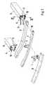
- FIG. 2is an exploded view of the bumper unit with individually illustrated holders, a cross member, a deformation member and a hitching towing arrangement;
- FIG. 3is a view of a free end of the cross member with the holder and the mounted deformation member viewed in the direction of arrow Z of FIG. 1;
- FIG. 4is a sectional view of the holder having expansion screws according to Line IV—IV of FIG. 2
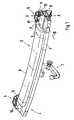
- a hitching towing arrangement 1is connected by way of a receiving device 2 , which can be fitted into a cross member 3 .
- the member 3is fastened by way of holders 4 , 5 arranged on the end side, in turn, to a vehicle body structure and to side members 6 of the vehicle respectively.
- a U-profile-shaped deformation member 7which is covered on the top side by a foam part 8 for a foot step, which is not shown, is connected with the cross member 3 .
- the cross member 3 , deformation member 7 and foam part 8 unitforms a rear-side bumper S with an integrated hitching towing arrangement 1 .
- the cross member 3preferably includes a closed box profile which, at its free ends, can be connected with the holders 4 , 5 .
- each holder 4 , 5has inner and outer pairs of arms 10 , 11 which are bent away at its vertical side edges and which reach over the member 3 from above and from below. A connection of these pairs 10 , 11 of arms with the member 3 takes place, for example, by means of welding.
- the expansion screws 12are arranged in the sleeve 14 in each case unencumbered with respect to the sleeve 14 along a certain length I, so that, in the case of a loading in the direction of the arrow P, the screw 12 can expand in the sleeve without friction and can contract again against this direction P of the arrow.
- a connection of the deformation member 7 with the side member 6takes place, for example, by means of screw devices 15 which are schematically represented by a line.
- the cross member 3has the preplaced deformation member 7 as a bumper unit which is surrounded by a so-called skin 20 or a preform.
Landscapes
- Engineering & Computer Science (AREA)
- Transportation (AREA)
- Mechanical Engineering (AREA)
- Body Structure For Vehicles (AREA)
Abstract
Description
Claims (18)
Applications Claiming Priority (3)
| Application Number | Priority Date | Filing Date | Title |
|---|---|---|---|
| DE10061491.4 | 2000-12-09 | ||
| DE10061491 | 2000-12-09 | ||
| DE10061491ADE10061491C1 (en) | 2000-12-09 | 2000-12-09 | Towing attachment for motor vehicle has cross member ends rigidly connected to respective mounting, with mountings and cross member fastened as assembly to body part of vehicle by longitudinally extending waisted bolts |
Publications (2)
| Publication Number | Publication Date |
|---|---|
| US20020113408A1 US20020113408A1 (en) | 2002-08-22 |
| US6626450B2true US6626450B2 (en) | 2003-09-30 |
Family
ID=7666572
Family Applications (1)
| Application Number | Title | Priority Date | Filing Date |
|---|---|---|---|
| US10/007,661Expired - LifetimeUS6626450B2 (en) | 2000-12-09 | 2001-12-10 | Bumper unit having a hitching towing arrangement and a method of making same |
Country Status (6)
| Country | Link |
|---|---|
| US (1) | US6626450B2 (en) |
| EP (1) | EP1213161B1 (en) |
| JP (1) | JP3914758B2 (en) |
| AT (1) | ATE319583T1 (en) |
| DE (1) | DE10061491C1 (en) |
| ES (1) | ES2256137T3 (en) |
Cited By (4)
| Publication number | Priority date | Publication date | Assignee | Title |
|---|---|---|---|---|
| US20050236808A1 (en)* | 2002-09-17 | 2005-10-27 | Johan Lier | Coupling assembly for vehicles |
| US8678423B1 (en)* | 2012-10-26 | 2014-03-25 | Hyundai Motor Company | Towing hook assembly for vehicle |
| US20180056739A1 (en)* | 2016-08-30 | 2018-03-01 | Horizon Global Americas Inc. | Detachable receiver |
| US9914332B2 (en)* | 2016-06-07 | 2018-03-13 | Ford Global Technologies, Llc | Trailer hitch assembly for a vehicle |
Families Citing this family (10)
| Publication number | Priority date | Publication date | Assignee | Title |
|---|---|---|---|---|
| SE523794C2 (en)* | 2002-07-10 | 2004-05-18 | Monoflex Sweden Ab | Tow bar structure |
| JP5095438B2 (en) | 2008-02-14 | 2012-12-12 | 富士重工業株式会社 | Car body rear structure with trailer hitch |
| ATE528422T1 (en) | 2009-08-14 | 2011-10-15 | Mayer Textilmaschf | PATTERN CHAIN WARMER AND METHOD FOR PRODUCING A PATTERN CHAIN |
| DE102010029394A1 (en)* | 2010-05-27 | 2011-12-01 | Scambia Industrial Developments Aktiengesellschaft | Rear hitch |
| DE102011122471A1 (en)* | 2011-12-24 | 2013-06-27 | Westfalia-Automotive Gmbh | Towing device for a vehicle |
| USD746215S1 (en)* | 2013-07-19 | 2015-12-29 | Robert N. Leavitt | Vehicle plow mount cover |
| DE102014007781B3 (en)* | 2014-05-21 | 2015-07-09 | Audi Ag | Rear end device for rear mounting on a vehicle body with tailgate |
| TWM502019U (en)* | 2014-12-03 | 2015-06-01 | Ya-Ming Ye | Structure of a shock absorbing article for packaging |
| DE102018101887A1 (en) | 2018-01-29 | 2019-08-01 | ACPS Automotive GmbH | Towing |
| DE102019110665A1 (en) | 2019-04-25 | 2020-10-29 | Khs Gmbh | Method for CIP cleaning a filling element of a filling machine and filling machine |
Citations (20)
| Publication number | Priority date | Publication date | Assignee | Title |
|---|---|---|---|---|
| DE290834C (en)* | ||||
| US2097006A (en) | 1937-03-25 | 1937-10-26 | Gilbert C Weis | Trailer drawbar attachment |
| US2747892A (en)* | 1954-10-20 | 1956-05-29 | James E Jones | Detachable bumper attached trailer hitch |
| GB2032052A (en) | 1978-09-06 | 1980-04-30 | Nissan Motor | A bumper structure which allows for thermal expansion of an energy-absorbing member thereof |
| US4385779A (en) | 1979-10-20 | 1983-05-31 | Nissan Motor Co., Ltd. | Connection structure for vehicle body parts |
| US4475856A (en)* | 1979-12-21 | 1984-10-09 | Telefonaktiebolaget L M Ericsson | Expansion screw with an expansion sleeve having an outer cylindrical surface and regions of greater and lesser wall thickness |
| GB2147257A (en) | 1983-09-30 | 1985-05-09 | Bergische Achsen Kotz Soehne | Connecting a tow bar and control cable support to an axle |
| US5094469A (en)* | 1989-11-29 | 1992-03-10 | Fuji Jukogyo Kabushiki Kaisha | Trailer hitch device for motor vehicles |
| US5149122A (en)* | 1991-04-26 | 1992-09-22 | Helber Robert A | Adjustable hitch assembly |
| DE4131275A1 (en) | 1991-09-20 | 1993-03-25 | Mahle Gmbh | Sectional fluid-cooled piston for I.C.- engine - has head accommodating piston rings connected by central screw arrangement to piston shaft |
| US5476279A (en)* | 1993-12-06 | 1995-12-19 | Klemetsen; Darrel | Trailer hitch |
| US5511813A (en)* | 1994-03-07 | 1996-04-30 | Kravitz; Harley A. | Adjustable width trailer hitch |
| US5561246A (en)* | 1993-11-10 | 1996-10-01 | Deutsche Aerospace Ag Patente | Biaxial rate gyro comprising elastic joint parts |
| US5598589A (en)* | 1992-07-09 | 1997-02-04 | Ideal Standard Spa | Hinge device for securing the seat and lid to a water closet pan |
| US5603191A (en)* | 1995-07-18 | 1997-02-18 | Wu; Ming-Hsin | Plastic door frame and method of mounting the same |
| DE19603873A1 (en) | 1996-02-03 | 1997-08-07 | Gerhard Dipl Ing Wohlhueter | Trailer attachment device |
| EP1008468A2 (en) | 1998-12-11 | 2000-06-14 | ORIS FAHRZEUGTEILE HANS RIEHLE GmbH | Mounting for drawbar |
| US6173984B1 (en)* | 1999-06-09 | 2001-01-16 | Jack Kay | Trailer hitch |
| US6234512B1 (en)* | 1999-11-22 | 2001-05-22 | Clark E. Bettenhausen | Trailer hitch |
| US6402179B1 (en)* | 2001-05-10 | 2002-06-11 | Ford Global Tech., Inc. | Lightweight towing cross member for a vehicle |
Family Cites Families (1)
| Publication number | Priority date | Publication date | Assignee | Title |
|---|---|---|---|---|
| DE3233813C1 (en)* | 1982-09-11 | 1983-11-03 | Daimler-Benz Ag, 7000 Stuttgart | Trailer coupling for vehicles |
- 2000
- 2000-12-09DEDE10061491Apatent/DE10061491C1/ennot_activeExpired - Lifetime
- 2001
- 2001-11-06ATAT01125470Tpatent/ATE319583T1/ennot_activeIP Right Cessation
- 2001-11-06ESES01125470Tpatent/ES2256137T3/ennot_activeExpired - Lifetime
- 2001-11-06EPEP01125470Apatent/EP1213161B1/ennot_activeExpired - Lifetime
- 2001-12-06JPJP2001373216Apatent/JP3914758B2/ennot_activeExpired - Fee Related
- 2001-12-10USUS10/007,661patent/US6626450B2/ennot_activeExpired - Lifetime
Patent Citations (20)
| Publication number | Priority date | Publication date | Assignee | Title |
|---|---|---|---|---|
| DE290834C (en)* | ||||
| US2097006A (en) | 1937-03-25 | 1937-10-26 | Gilbert C Weis | Trailer drawbar attachment |
| US2747892A (en)* | 1954-10-20 | 1956-05-29 | James E Jones | Detachable bumper attached trailer hitch |
| GB2032052A (en) | 1978-09-06 | 1980-04-30 | Nissan Motor | A bumper structure which allows for thermal expansion of an energy-absorbing member thereof |
| US4385779A (en) | 1979-10-20 | 1983-05-31 | Nissan Motor Co., Ltd. | Connection structure for vehicle body parts |
| US4475856A (en)* | 1979-12-21 | 1984-10-09 | Telefonaktiebolaget L M Ericsson | Expansion screw with an expansion sleeve having an outer cylindrical surface and regions of greater and lesser wall thickness |
| GB2147257A (en) | 1983-09-30 | 1985-05-09 | Bergische Achsen Kotz Soehne | Connecting a tow bar and control cable support to an axle |
| US5094469A (en)* | 1989-11-29 | 1992-03-10 | Fuji Jukogyo Kabushiki Kaisha | Trailer hitch device for motor vehicles |
| US5149122A (en)* | 1991-04-26 | 1992-09-22 | Helber Robert A | Adjustable hitch assembly |
| DE4131275A1 (en) | 1991-09-20 | 1993-03-25 | Mahle Gmbh | Sectional fluid-cooled piston for I.C.- engine - has head accommodating piston rings connected by central screw arrangement to piston shaft |
| US5598589A (en)* | 1992-07-09 | 1997-02-04 | Ideal Standard Spa | Hinge device for securing the seat and lid to a water closet pan |
| US5561246A (en)* | 1993-11-10 | 1996-10-01 | Deutsche Aerospace Ag Patente | Biaxial rate gyro comprising elastic joint parts |
| US5476279A (en)* | 1993-12-06 | 1995-12-19 | Klemetsen; Darrel | Trailer hitch |
| US5511813A (en)* | 1994-03-07 | 1996-04-30 | Kravitz; Harley A. | Adjustable width trailer hitch |
| US5603191A (en)* | 1995-07-18 | 1997-02-18 | Wu; Ming-Hsin | Plastic door frame and method of mounting the same |
| DE19603873A1 (en) | 1996-02-03 | 1997-08-07 | Gerhard Dipl Ing Wohlhueter | Trailer attachment device |
| EP1008468A2 (en) | 1998-12-11 | 2000-06-14 | ORIS FAHRZEUGTEILE HANS RIEHLE GmbH | Mounting for drawbar |
| US6173984B1 (en)* | 1999-06-09 | 2001-01-16 | Jack Kay | Trailer hitch |
| US6234512B1 (en)* | 1999-11-22 | 2001-05-22 | Clark E. Bettenhausen | Trailer hitch |
| US6402179B1 (en)* | 2001-05-10 | 2002-06-11 | Ford Global Tech., Inc. | Lightweight towing cross member for a vehicle |
Cited By (6)
| Publication number | Priority date | Publication date | Assignee | Title |
|---|---|---|---|---|
| US20050236808A1 (en)* | 2002-09-17 | 2005-10-27 | Johan Lier | Coupling assembly for vehicles |
| US8678423B1 (en)* | 2012-10-26 | 2014-03-25 | Hyundai Motor Company | Towing hook assembly for vehicle |
| US9914332B2 (en)* | 2016-06-07 | 2018-03-13 | Ford Global Technologies, Llc | Trailer hitch assembly for a vehicle |
| US20180056739A1 (en)* | 2016-08-30 | 2018-03-01 | Horizon Global Americas Inc. | Detachable receiver |
| US10836225B2 (en)* | 2016-08-30 | 2020-11-17 | Horizon Global Americas Inc. | Detachable receiver |
| US11752817B2 (en) | 2016-08-30 | 2023-09-12 | Horizon Global Americas Inc. | Detachable receiver |
Also Published As
| Publication number | Publication date |
|---|---|
| JP3914758B2 (en) | 2007-05-16 |
| EP1213161A2 (en) | 2002-06-12 |
| EP1213161B1 (en) | 2006-03-08 |
| ATE319583T1 (en) | 2006-03-15 |
| EP1213161A3 (en) | 2002-12-11 |
| JP2002211446A (en) | 2002-07-31 |
| US20020113408A1 (en) | 2002-08-22 |
| ES2256137T3 (en) | 2006-07-16 |
| DE10061491C1 (en) | 2002-04-18 |
Similar Documents
| Publication | Publication Date | Title |
|---|---|---|
| US6626450B2 (en) | Bumper unit having a hitching towing arrangement and a method of making same | |
| JP4860374B2 (en) | Towing hook mounting structure | |
| US7942223B2 (en) | Vehicular radiator supporting apparatus | |
| US8453786B2 (en) | Front section for a motor vehicle | |
| US20060163843A1 (en) | Trailer hitch assembly | |
| US9145035B2 (en) | Collapsible step platform and receiver post | |
| US7971896B2 (en) | Towing hitch apparatus and method | |
| US20100019542A1 (en) | Front-end frame concept for the body structure on a multiple platform | |
| US10259305B2 (en) | Energy supply system for a motor vehicle | |
| US5678839A (en) | Vehicle trailer hitch | |
| US8696003B2 (en) | Front axle support with arrangement of a steering gear and a front axle stabilizer | |
| MXPA01011678A (en) | Plug-in tow device. | |
| US7938446B2 (en) | Vehicle body of a convertible vehicle | |
| KR102430535B1 (en) | Vehicle trailer tow connection device with noise prevention structure | |
| US7845710B2 (en) | Underride compatibility apparatus for a vehicle | |
| US7815248B2 (en) | Rearward-side vehicle body structure | |
| CN102862452B (en) | The cover plate of the functor stretched out at the body structure at the front side of motor vehicles or rear side | |
| US10202010B2 (en) | Motor vehicle | |
| KR101315882B1 (en) | Trailer hitch connection structure | |
| RU2622317C2 (en) | Fixation of coupling device with force distribution bracket | |
| US6129384A (en) | Bolt-on part, especially a bumper of a motor vehicle | |
| US20040012213A1 (en) | Bumper assembly | |
| AU2013221947B2 (en) | Trailer hitch shock dampening system | |
| US20030080584A1 (en) | Arrangement for fastening a body element | |
| US8297680B2 (en) | Device for reinforcement |
Legal Events
| Date | Code | Title | Description |
|---|---|---|---|
| AS | Assignment | Owner name:DR. ING. H.C.F. PORSCHE AG, GERMANY Free format text:ASSIGNMENT OF ASSIGNORS INTEREST;ASSIGNORS:BRAUN, WALTER;PALMER, EBERHARD;REEL/FRAME:012846/0836 Effective date:20020322 | |
| STCF | Information on status: patent grant | Free format text:PATENTED CASE | |
| FPAY | Fee payment | Year of fee payment:4 | |
| AS | Assignment | Owner name:DR. ING. H.C.F. PORSCHE AKTIENGESELLSCHAFT (COMPAN Free format text:MERGER;ASSIGNOR:DR. ING. H.C.F. PORSCHE AKTIENGESELLSCHAFT (COMPANY NUMBER 5211);REEL/FRAME:021040/0147 Effective date:20071113 | |
| AS | Assignment | Owner name:PORSCHE ZWISCHENHOLDING GMBH, GERMANY Free format text:MERGER;ASSIGNOR:DR. ING. H.C.F. PORSCHE AKTIENGESELLSCHAFT;REEL/FRAME:025227/0699 Effective date:20091125 Owner name:DR. ING. H.C.F. PORSCHE AKTIENGESELLSCHAFT, GERMAN Free format text:CHANGE OF NAME;ASSIGNOR:PORSCHE ZWISCHENHOLDING GMBH;REEL/FRAME:025227/0747 Effective date:20091130 | |
| FPAY | Fee payment | Year of fee payment:8 | |
| FPAY | Fee payment | Year of fee payment:12 |