US6626011B2 - Method of manufacturing a monomode fluoride optical fiber, and an optical amplifier using such a fiber - Google Patents
Method of manufacturing a monomode fluoride optical fiber, and an optical amplifier using such a fiberDownload PDFInfo
- Publication number
- US6626011B2 US6626011B2US09/068,540US6854098AUS6626011B2US 6626011 B2US6626011 B2US 6626011B2US 6854098 AUS6854098 AUS 6854098AUS 6626011 B2US6626011 B2US 6626011B2
- Authority
- US
- United States
- Prior art keywords
- preform
- fiber
- optical fiber
- mother
- outer tube
- Prior art date
- Legal status (The legal status is an assumption and is not a legal conclusion. Google has not performed a legal analysis and makes no representation as to the accuracy of the status listed.)
- Expired - Fee Related, expires
Links
- 239000013307optical fiberSubstances0.000titleclaimsabstractdescription41
- 239000000835fiberSubstances0.000titleclaimsabstractdescription34
- 238000004519manufacturing processMethods0.000titleclaimsabstractdescription11
- 230000003287optical effectEffects0.000titleclaimsabstractdescription9
- KRHYYFGTRYWZRS-UHFFFAOYSA-MFluoride anionChemical compound[F-]KRHYYFGTRYWZRS-UHFFFAOYSA-M0.000title1
- 238000012681fiber drawingMethods0.000claimsabstractdescription32
- 239000000463materialSubstances0.000claimsdescription11
- 238000000034methodMethods0.000claimsdescription11
- 230000007704transitionEffects0.000claimsdescription10
- 239000005383fluoride glassSubstances0.000claimsdescription9
- -1rare earth ionsChemical class0.000claimsdescription7
- 229910052761rare earth metalInorganic materials0.000claimsdescription7
- 238000005253claddingMethods0.000description9
- 238000010438heat treatmentMethods0.000description7
- VYPSYNLAJGMNEJ-UHFFFAOYSA-NSilicium dioxideChemical compoundO=[Si]=OVYPSYNLAJGMNEJ-UHFFFAOYSA-N0.000description5
- 239000005371ZBLANSubstances0.000description4
- 229910052788bariumInorganic materials0.000description3
- 238000005266castingMethods0.000description3
- 239000011521glassSubstances0.000description3
- 239000000203mixtureSubstances0.000description3
- 230000002093peripheral effectEffects0.000description3
- 229910052782aluminiumInorganic materials0.000description2
- DSAJWYNOEDNPEQ-UHFFFAOYSA-Nbarium atomChemical compound[Ba]DSAJWYNOEDNPEQ-UHFFFAOYSA-N0.000description2
- 238000005229chemical vapour depositionMethods0.000description2
- 238000005516engineering processMethods0.000description2
- 229910052731fluorineInorganic materials0.000description2
- 229910052746lanthanumInorganic materials0.000description2
- 229910052744lithiumInorganic materials0.000description2
- 229920000642polymerPolymers0.000description2
- 238000010106rotational castingMethods0.000description2
- 239000000377silicon dioxideSubstances0.000description2
- 229910052708sodiumInorganic materials0.000description2
- 239000011734sodiumSubstances0.000description2
- 239000007787solidSubstances0.000description2
- 229910052726zirconiumInorganic materials0.000description2
- KLZUFWVZNOTSEM-UHFFFAOYSA-KAluminium flourideChemical compoundF[Al](F)FKLZUFWVZNOTSEM-UHFFFAOYSA-K0.000description1
- 229910052691ErbiumInorganic materials0.000description1
- PXGOKWXKJXAPGV-UHFFFAOYSA-NFluorineChemical compoundFFPXGOKWXKJXAPGV-UHFFFAOYSA-N0.000description1
- DGAQECJNVWCQMB-PUAWFVPOSA-MIlexoside XXIXChemical compoundC[C@@H]1CC[C@@]2(CC[C@@]3(C(=CC[C@H]4[C@]3(CC[C@@H]5[C@@]4(CC[C@@H](C5(C)C)OS(=O)(=O)[O-])C)C)[C@@H]2[C@]1(C)O)C)C(=O)O[C@H]6[C@@H]([C@H]([C@@H]([C@H](O6)CO)O)O)O.[Na+]DGAQECJNVWCQMB-PUAWFVPOSA-M0.000description1
- WHXSMMKQMYFTQS-UHFFFAOYSA-NLithiumChemical compound[Li]WHXSMMKQMYFTQS-UHFFFAOYSA-N0.000description1
- 229910052779NeodymiumInorganic materials0.000description1
- 229910052777PraseodymiumInorganic materials0.000description1
- QCWXUUIWCKQGHC-UHFFFAOYSA-NZirconiumChemical compound[Zr]QCWXUUIWCKQGHC-UHFFFAOYSA-N0.000description1
- 239000000853adhesiveSubstances0.000description1
- 230000001070adhesive effectEffects0.000description1
- XAGFODPZIPBFFR-UHFFFAOYSA-NaluminiumChemical compound[Al]XAGFODPZIPBFFR-UHFFFAOYSA-N0.000description1
- 238000004891communicationMethods0.000description1
- 238000001816coolingMethods0.000description1
- 238000002425crystallisationMethods0.000description1
- 230000008025crystallizationEffects0.000description1
- 238000010586diagramMethods0.000description1
- 230000000694effectsEffects0.000description1
- UYAHIZSMUZPPFV-UHFFFAOYSA-NerbiumChemical compound[Er]UYAHIZSMUZPPFV-UHFFFAOYSA-N0.000description1
- 239000011737fluorineSubstances0.000description1
- FZLIPJUXYLNCLC-UHFFFAOYSA-Nlanthanum atomChemical compound[La]FZLIPJUXYLNCLC-UHFFFAOYSA-N0.000description1
- 238000005259measurementMethods0.000description1
- 238000002844meltingMethods0.000description1
- 230000008018meltingEffects0.000description1
- 239000006060molten glassSubstances0.000description1
- QEFYFXOXNSNQGX-UHFFFAOYSA-Nneodymium atomChemical compound[Nd]QEFYFXOXNSNQGX-UHFFFAOYSA-N0.000description1
- PUDIUYLPXJFUGB-UHFFFAOYSA-Npraseodymium atomChemical compound[Pr]PUDIUYLPXJFUGB-UHFFFAOYSA-N0.000description1
- 238000005086pumpingMethods0.000description1
- PUZPDOWCWNUUKD-UHFFFAOYSA-Msodium fluorideChemical compound[F-].[Na+]PUZPDOWCWNUUKD-UHFFFAOYSA-M0.000description1
- 230000003595spectral effectEffects0.000description1
- 238000001228spectrumMethods0.000description1
- BYMUNNMMXKDFEZ-UHFFFAOYSA-KtrifluorolanthanumChemical compoundF[La](F)FBYMUNNMMXKDFEZ-UHFFFAOYSA-K0.000description1
- 239000011800void materialSubstances0.000description1
- OMQSJNWFFJOIMO-UHFFFAOYSA-Jzirconium tetrafluorideChemical compoundF[Zr](F)(F)FOMQSJNWFFJOIMO-UHFFFAOYSA-J0.000description1
Images


Classifications
- C—CHEMISTRY; METALLURGY
- C03—GLASS; MINERAL OR SLAG WOOL
- C03B—MANUFACTURE, SHAPING, OR SUPPLEMENTARY PROCESSES
- C03B37/00—Manufacture or treatment of flakes, fibres, or filaments from softened glass, minerals, or slags
- C03B37/01—Manufacture of glass fibres or filaments
- C03B37/02—Manufacture of glass fibres or filaments by drawing or extruding, e.g. direct drawing of molten glass from nozzles; Cooling fins therefor
- C03B37/025—Manufacture of glass fibres or filaments by drawing or extruding, e.g. direct drawing of molten glass from nozzles; Cooling fins therefor from reheated softened tubes, rods, fibres or filaments, e.g. drawing fibres from preforms
- C03B37/027—Fibres composed of different sorts of glass, e.g. glass optical fibres
- C03B37/02754—Solid fibres drawn from hollow preforms
- C—CHEMISTRY; METALLURGY
- C03—GLASS; MINERAL OR SLAG WOOL
- C03B—MANUFACTURE, SHAPING, OR SUPPLEMENTARY PROCESSES
- C03B37/00—Manufacture or treatment of flakes, fibres, or filaments from softened glass, minerals, or slags
- C03B37/01—Manufacture of glass fibres or filaments
- C03B37/012—Manufacture of preforms for drawing fibres or filaments
- C03B37/01205—Manufacture of preforms for drawing fibres or filaments starting from tubes, rods, fibres or filaments
- C03B37/01211—Manufacture of preforms for drawing fibres or filaments starting from tubes, rods, fibres or filaments by inserting one or more rods or tubes into a tube
- C—CHEMISTRY; METALLURGY
- C03—GLASS; MINERAL OR SLAG WOOL
- C03C—CHEMICAL COMPOSITION OF GLASSES, GLAZES OR VITREOUS ENAMELS; SURFACE TREATMENT OF GLASS; SURFACE TREATMENT OF FIBRES OR FILAMENTS MADE FROM GLASS, MINERALS OR SLAGS; JOINING GLASS TO GLASS OR OTHER MATERIALS
- C03C13/00—Fibre or filament compositions
- C03C13/04—Fibre optics, e.g. core and clad fibre compositions
- C03C13/041—Non-oxide glass compositions
- C03C13/042—Fluoride glass compositions
- C—CHEMISTRY; METALLURGY
- C03—GLASS; MINERAL OR SLAG WOOL
- C03B—MANUFACTURE, SHAPING, OR SUPPLEMENTARY PROCESSES
- C03B2201/00—Type of glass produced
- C03B2201/80—Non-oxide glasses or glass-type compositions
- C03B2201/82—Fluoride glasses, e.g. ZBLAN glass
- C—CHEMISTRY; METALLURGY
- C03—GLASS; MINERAL OR SLAG WOOL
- C03B—MANUFACTURE, SHAPING, OR SUPPLEMENTARY PROCESSES
- C03B2203/00—Fibre product details, e.g. structure, shape
- C03B2203/10—Internal structure or shape details
- C03B2203/22—Radial profile of refractive index, composition or softening point
- C03B2203/24—Single mode [SM or monomode]
- C—CHEMISTRY; METALLURGY
- C03—GLASS; MINERAL OR SLAG WOOL
- C03B—MANUFACTURE, SHAPING, OR SUPPLEMENTARY PROCESSES
- C03B2205/00—Fibre drawing or extruding details
- C03B2205/12—Drawing solid optical fibre directly from a hollow preform
- C03B2205/14—Drawing solid optical fibre directly from a hollow preform comprising collapse of an outer tube onto an inner central solid preform rod
- C—CHEMISTRY; METALLURGY
- C03—GLASS; MINERAL OR SLAG WOOL
- C03B—MANUFACTURE, SHAPING, OR SUPPLEMENTARY PROCESSES
- C03B2205/00—Fibre drawing or extruding details
- C03B2205/12—Drawing solid optical fibre directly from a hollow preform
- C03B2205/16—Drawing solid optical fibre directly from a hollow preform the drawn fibre consisting of circularly symmetric core and clad
Definitions
- the present inventionrelates in general to manufacturing a monomode preform and to the corresponding monomode optical fiber. It is applicable to the field of optical fiber telecommunications. By way of non-limiting example, it applies to polymer, fluoride glass, etc . . . technologies.
- the inventioncan be used in making economically viable optical amplifiers possessing low splice losses between the amplifying fiber portion and the line fibers, and possessing spectral attenuation compatible with the required pumping efficiencies.
- Optical fiber manufacturecomprises two successive steps, namely making a preform, and drawing said preform down to obtain an optical fiber.
- Chemical vapor deposition (CVD) type techniquesas summarized in the document entitled “Preform technologies for optical fibers” by D. Dorn and C. Le Sergent, published in “Electrical Communication”, Vol. 62, No. 3/4, 1988, can be used for making a preform out of polymer or fluoride glass, but that does not give satisfactory results, particularly in terms of attenuation. Under such circumstances, a technique of the “built-in casting” type is then used, which technique is well known to the person skilled in the art and is described in the article by S. Mitachi, T. Miyashita, and T. Kanamori published in Electronics Letters, Vol. 17, pp. 591 et seq. (1981). That technique uses a hollow cylindrical mold having a closed bottom.
- Molten glass material for forming the claddingis poured into the mold. Before the cladding glass material forming a solid cylinder in the mold has solidified completely, a cylindrical central portion is removed from the solid cylinder and the resulting void is filled in with molten core glass material. As a result, after cooling, an initial preform is obtained in the form of a bar having a central core zone and a peripheral cladding zone. During the fiber-drawing step, the optical fiber is drawn from said preform. The fiber comprises both a core and cladding surrounding the core. The ratio of core diameter to fiber diameter is identical to the ratio of core zone diameter to preform diameter. Diameter ratio (core diameter/total diameter) is thus conserved between preform and fiber.
- the initial preformis stretched to form a “mother” preform possessing a core zone of diameter smaller than that of the initial preform.
- This mother preformis then inserted into an outer tubular sleeve of cladding glass, such that after drawing down, an optical fiber is obtained possessing the desired ratio of core diameter to fiber diameter.
- the outer tubemay be obtained by centrifuging or “rotational casting”. If the outer tube does not enable the desired ratio to be obtained, a second mother preform can be made by stretching the first mother preform with its outer tube. This second mother preform is then inserted into a second outer tube. The operation of inserting a mother preform into an outer tube can thus be repeated as many times as necessary to achieve the desired ratio. It is also possible to insert the mother preform into a plurality of concentric outer tubes and to draw the fiber from the resulting assembly.
- the fiber-drawing stepconsists in heating one of the ends of the assembly made up of mother preform and outer tube and in drawing an optical fiber from the preform that is melted in this way by heating.
- FIG. 1which is a longitudinal section through such an assembly 1
- the mother preform 11is inserted into the outer tube 10 and leaves an empty volume 12 between the cylindrical outside surface of the mother preform 11 and the cylindrical inside surface of the outer tube 10 .
- very intense heatingis applied to the assembly 10 - 11 so as to obtain local melting in the peripheral cladding zone 110 of the mother preform 11 and in the outer tube 10 so as to fill in the initially empty volume 12 .
- a first object of the inventionis to provide a monomode preform suitable for making a monomode optical fiber.
- a second object of the inventionis to provide a method of manufacturing such a monomode optical fiber.
- Another object of the inventionis to provide a monomode optical fiber possessing a core that is substantially circular and centered.
- a monomode preformcomprising a mother preform housed in an outer tube and leaving an empty volume between an outside surface of the mother preform and an inside surface of the outer tube, is characterized in that an intermediate tube is inserted in said empty volume, the intermediate tube possessing viscosity at fiber-drawing temperature which is less than the viscosity(ies) at fiber-drawing temperature of said mother preform and of said outer tube.
- the preformis made of fluoride glass, said intermediate tube possessing a vitreous transition temperature lower than the vitreous transition temperature(s) of said mother preform and of said outer tube.
- the core zone of the mother preformmay be doped with rare earth ions.
- the inventionalso provides a method of manufacturing a monomode optical fiber comprising the step of drawing a fiber from a monomode preform of the above-described type.
- the fiber-drawing temperaturelies substantially in the range 320° C. to 330° C.
- fiber-drawingis performed on a preform whose core zone is doped.
- Such a doped optical fibercan be used to make an optical amplifier or a laser source.
- FIG. 1, described above,is a fragmentary longitudinal axial section view of an outer tube having a mother preform inserted therein to make a monomode optical fiber by the prior art method;
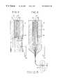
- FIG. 2is a fragmentary longitudinal axial section view of an outer tube into which there have been inserted both a mother preform and an intermediate tube for making a monomode optical fiber in accordance with the invention
- FIG. 3is a diagram showing how the FIG. 2 preform is drawn into a fiber.
- FIG. 4shows an optical amplifier
- a preform 2 of the inventiontypically a monomode preform, comprises a mother preform 22 received in an outer tube 20 . They are held securely relative to each other by mechanical means (not shown).
- an intermediate tube 21that is not held and that has been obtained by centrifuging is disposed between the mother preform 22 and the outer tube 20 .
- the intermediate tube 21possesses viscosity at the fiber-drawing temperature which is lower than the viscosity(ies) at the fiber-drawing temperature of the mother preform 22 and of the outer tube 20 .
- the mother preform 22comprises a core zone 221 and a peripheral cladding zone 220 around the core zone 221 .
- the preformis made of fluoride glass.
- the characteristic whereby the intermediate tube 21 possesses viscosity at the fiber-drawing temperature that is less than the viscosity(ies) at the fiber-drawing temperature of the mother preform 22 and of the outer tube 20means that the intermediate tube 21 possesses a vitreous transition temperature lower than the vitreous transition temperature(s) of the mother preform and of the outer tube.
- the core zone 221is defined by a molar composition substantially equal to:
- the sheath zone 220 and the outer tube 20are defined by a molar composition substantially equal to:
- the intermediate tube 21is defined by a molar composition substantially equal to:
- the index difference between the cladding zone and the core zonecan be much larger, particularly for an amplifying fiber.
- Zr, Ba, La, Al, Na, Li, and Fdesignate respectively zirconium, barium, lanthanum, aluminum, sodium, lithium, and fluorine.
- the core zone 221comprises 54% zirconium tetrafluoride, 23% barium bifluoride, 4% lanthanum trifluoride, 3% aluminum trifluoride, and 16% sodium monofluoride.
- the core zone 221is defined by a viscosity that is equal to about 10 6 Po
- the cladding zone 220 and the outer tube 20by a viscosity equal to about 10 5.5 Po
- the intermediate tube 21by a viscosity equal to about 10 5 Po.
- Pois the abbreviation for the Poise unit of measurement which is equal to 0.1 pascal-seconds.
- fiber-drawingcomprises the step 25 of heating one of the ends of the preform, typically by means of an oven, and the step 24 of drawing the fiber F from said heated preform.
- the preformboth between the outside cylindrical surface of the intermediate tube 21 and the inside cylindrical surface of the outer tube 20 , and also between the inside cylindrical surface of the intermediate tube 21 and the outside cylindrical surface of the mother preform 22 , there exist cylindrical volumes 23 that are empty of any preform material.
- the intermediate tube 21possesses viscosity at the fiber-drawing temperature which is less than the viscosity(ies) at the fiber-drawing temperature of the mother preform 22 and of the outer tube 20 .
- heatinggives rise to “softening” of the intermediate tube 21 as shown in the bottom portion of the preform in FIG. 3, thereby filling the empty volumes both between the cylindrical outside surface of the intermediate tube 21 and the cylindrical inside surface of the outer tube 20 , and between the cylindrical inside surface of the intermediate tube 21 and the cylindrical outside surface of the mother preform 22 .
- the material constituting the intermediate tube 21is intended to become an integral portion of the resulting optical fiber F.
- the fiber-drawing temperature delivered by the heating 25can be much lower than the prior art fiber-drawing temperature for preforms of the type shown in FIG. 1 . It is not necessary to apply as high a fiber-drawing temperature as in the prior art for the purpose of filling the empty volumes 23 . This gives rise to less eccentricity and to less deformation of the core of the fiber F. In addition, this lower temperature minimizes the risk of crystallization which is partially responsible for attenuation.
- the inventioncan be applied to making an optical amplifier 3 of the type shown in FIG. 4 .
- the amplifier 3comprises in cascade: an isolator 30 ; a multiplexer 31 ; a first portion of intermediate fiber 33 ; a portion of amplifying fiber F′ in accordance with the invention; a second portion of intermediate fiber 34 ; a demultiplexer 35 ; and an isolator 36 .
- the multiplexerreceives the signal from the isolator 30 and a pump signal produced by a diode 32 .
- the demultiplexer 35produces a residual pump signal PR.
- Silica fibersare doped with rare earth ions of the neodymium type to provide a fiber amplifier capable of amplifying an optical signal in the spectrum range 1.30 ⁇ m to 1.36 ⁇ m.
- a fluoride glass fiberis therefore used which is doped with rare earth ions (known as ZBLAN) of the praseodymium type Pr 3+ for wavelengths of 1.3 ⁇ m or of the erbium type Er 3+ for wavelengths of 1.55 ⁇ m.
- the amplifying doped fiber F′is connected in series between the first intermediate fiber portion 33 and the second intermediate fiber portion 34 by splicing at 40 and 41 .
- the splices 40 and 41are typically made by means of an index-matching adhesive. Rare earth ion doping is performed in the core zone 221 during manufacture of the mother preform (FIGS. 2 and 3 ). Since the core of a fiber F′ that results from drawing down such a preform is particularly well centered and circular, losses at the splices 40 and 41 are very low, typically 0.15 dB.
- optical fiber of the inventionwhich is doped with rare earth ions to constitute a laser source.
- the laser sourcethen comprises two resonance reflector means at opposite ends of the doped fiber portion.
Landscapes
- Chemical & Material Sciences (AREA)
- Engineering & Computer Science (AREA)
- Organic Chemistry (AREA)
- Life Sciences & Earth Sciences (AREA)
- Geochemistry & Mineralogy (AREA)
- Materials Engineering (AREA)
- General Life Sciences & Earth Sciences (AREA)
- Manufacturing & Machinery (AREA)
- Optics & Photonics (AREA)
- Chemical Kinetics & Catalysis (AREA)
- General Chemical & Material Sciences (AREA)
- Physics & Mathematics (AREA)
- Manufacture, Treatment Of Glass Fibers (AREA)
- Glass Compositions (AREA)
- Lasers (AREA)
Abstract
Description
| ZrF4 | BaF2 | LaF3 | AlF3 | NaF |
| 54% | 23% | 4% | 3% | 16% |
| ZrF4 | BaF2 | LaF3 | AlF3 | NaF |
| 53% | 19% | 4% | 4% | 20% |
| ZrF4 | BaF2 | LaF3 | AlF3 | NaF | LiF | ||
| 52% | 18% | 4% | 4% | 20% | 2% | ||
Claims (14)
Applications Claiming Priority (4)
| Application Number | Priority Date | Filing Date | Title |
|---|---|---|---|
| FR9513416AFR2741061B1 (en) | 1995-11-13 | 1995-11-13 | METHOD FOR MANUFACTURING SINGLE-MODE OPTICAL FIBER AND OPTICAL AMPLIFIER USING SUCH FIBER |
| FR9513416 | 1995-11-13 | ||
| FR95/13416 | 1995-11-13 | ||
| PCT/FR1996/001752WO1997018169A1 (en) | 1995-11-13 | 1996-11-07 | Method for making a single-mode optical fibre and optical amplifier using said fibre |
Publications (2)
| Publication Number | Publication Date |
|---|---|
| US20010045109A1 US20010045109A1 (en) | 2001-11-29 |
| US6626011B2true US6626011B2 (en) | 2003-09-30 |
Family
ID=9484504
Family Applications (1)
| Application Number | Title | Priority Date | Filing Date |
|---|---|---|---|
| US09/068,540Expired - Fee RelatedUS6626011B2 (en) | 1995-11-13 | 1996-11-07 | Method of manufacturing a monomode fluoride optical fiber, and an optical amplifier using such a fiber |
Country Status (10)
| Country | Link |
|---|---|
| US (1) | US6626011B2 (en) |
| EP (1) | EP0861215B1 (en) |
| JP (1) | JP2000500728A (en) |
| AT (1) | ATE206693T1 (en) |
| AU (1) | AU719124B2 (en) |
| DE (1) | DE69615851T2 (en) |
| FR (1) | FR2741061B1 (en) |
| IL (1) | IL119599A (en) |
| WO (1) | WO1997018169A1 (en) |
| ZA (1) | ZA969529B (en) |
Cited By (9)
| Publication number | Priority date | Publication date | Assignee | Title |
|---|---|---|---|---|
| US20040160714A1 (en)* | 2001-04-24 | 2004-08-19 | Vlt Corporation, A Texas Corporation | Components having actively controlled circuit elements |
| US20040163420A1 (en)* | 2003-01-06 | 2004-08-26 | Dowd Edward Michael | Method of fusing and stretching a large diameter optical waveguide |
| US20040259051A1 (en)* | 2001-12-28 | 2004-12-23 | Nobel Biocare Ab | Arrangement and device for using a template to form holes for implants in bone, preferably jaw bone |
| US20060008763A1 (en)* | 2002-12-30 | 2006-01-12 | Izidor Brajnovic | Device and arrangement for fixture installation |
| US20070214841A1 (en)* | 2004-04-27 | 2007-09-20 | Dätwyler Fiber Optics Sa | Method for Fabricating an Optical Fiber, Preform for Fabricating an Optical Fiber, Optical Fiber and Apparatus |
| US20070220924A1 (en)* | 2004-04-27 | 2007-09-27 | Dätwyler Fiber Optics Sa | Method for Fabricating an Optical Fiber, Preform for Fabricating an Optical fiber, Optical Fiber and Apparatus |
| US20080047303A1 (en)* | 2006-08-25 | 2008-02-28 | National Sun Yat-Sen University | Indirect heat type double-clad crystal fiber fabrication method |
| US20140186645A1 (en)* | 2013-01-02 | 2014-07-03 | Ofs Fitel, Llc | Manufacture of bend insensitive multimode optical fiber |
| US11079538B2 (en)* | 2016-01-20 | 2021-08-03 | Schott Corporation, Inc. | Foveal image inverter |
Families Citing this family (5)
| Publication number | Priority date | Publication date | Assignee | Title |
|---|---|---|---|---|
| GB9602080D0 (en)* | 1996-02-02 | 1996-04-03 | Pfizer Ltd | Pharmaceutical compounds |
| US20030230113A1 (en)* | 2002-06-12 | 2003-12-18 | Patrick Gedeon | Methods for manufacturing glass articles |
| CN100395203C (en)* | 2005-08-17 | 2008-06-18 | 长飞光纤光缆有限公司 | A method for manufacturing a large-size low-water peak optical fiber preform |
| US20070125128A1 (en)* | 2006-10-09 | 2007-06-07 | Sanket Shah | Optical fiber perform cone shaping or preparation method |
| FR2963787B1 (en)* | 2010-08-10 | 2012-09-21 | Draka Comteq France | PROCESS FOR PRODUCING AN OPTICAL FIBER PREFORM |
Citations (17)
| Publication number | Priority date | Publication date | Assignee | Title |
|---|---|---|---|---|
| US3877912A (en)* | 1973-10-09 | 1975-04-15 | Sumitomo Electric Industries | Method of producing an optical transmission line |
| GB1473779A (en) | 1974-11-13 | 1977-05-18 | Gen Cable Corp | Optical guides |
| JPS53125853A (en)* | 1977-04-11 | 1978-11-02 | Hitachi Ltd | Production of optical fibers |
| JPS5644024A (en)* | 1974-07-18 | 1981-04-23 | Svenska Flaektfabriken Ab | Air purifier |
| US4283213A (en) | 1979-10-22 | 1981-08-11 | International Telephone And Telegraph Corporation | Method of fabrication of single mode optical fibers or waveguides |
| GB2071351A (en) | 1979-08-27 | 1981-09-16 | Northern Telecom Ltd | Manufacture of monomode fibers |
| US4596589A (en) | 1984-02-09 | 1986-06-24 | Perry Gregory A | Method for producing a single mode fiber preform |
| WO1989000707A1 (en) | 1987-07-17 | 1989-01-26 | Spectran Corporation | Oxide coatings for fluoride glass |
| US4938562A (en)* | 1989-07-14 | 1990-07-03 | Spectran Corporation | Oxide coatings for fluoride glass |
| US4975102A (en)* | 1979-10-25 | 1990-12-04 | Nippon Telegraph & Telephone Public Corporation | Optical transmission fiber and process for producing the same |
| US4978377A (en)* | 1988-12-09 | 1990-12-18 | Alcatel N.V. | Method of assembling a fiber optic preform from discrete preformed elements |
| EP0568097A1 (en) | 1992-05-01 | 1993-11-03 | Sumitomo Electric Industries, Limited | Lead-containing fluoride glass, optical fiber and process for producing it |
| US5560759A (en)* | 1994-11-14 | 1996-10-01 | Lucent Technologies Inc. | Core insertion method for making optical fiber preforms and optical fibers fabricated therefrom |
| US5573571A (en)* | 1994-12-01 | 1996-11-12 | Lucent Technologies Inc. | Method for making optical fiber preforms and optical fibers fabricated therefrom |
| US5618326A (en)* | 1991-09-30 | 1997-04-08 | British Telecommunications Public Limited Company | Surface treatment of halide glass articles |
| US5656056A (en)* | 1994-03-16 | 1997-08-12 | Cselt-Centro Studi E Laboratori Telecomunicazioni S.P.A. | Method for the fabrication of fluoride glass single mode optical fibers with flowing of an etchant through the fiber preform |
| US5958103A (en)* | 1995-03-06 | 1999-09-28 | Hoya Corporation | Process for producing preform for glass fiber and process for producing glass fiber |
Family Cites Families (2)
| Publication number | Priority date | Publication date | Assignee | Title |
|---|---|---|---|---|
| JP3108210B2 (en)* | 1992-08-03 | 2000-11-13 | 古河電気工業株式会社 | Fluoride glass optical waveguide |
| JP3220821B2 (en)* | 1993-02-15 | 2001-10-22 | 日本電信電話株式会社 | Method for manufacturing single mode optical fiber |
- 1995
- 1995-11-13FRFR9513416Apatent/FR2741061B1/ennot_activeExpired - Fee Related
- 1996
- 1996-11-07ATAT96938269Tpatent/ATE206693T1/enactive
- 1996-11-07DEDE69615851Tpatent/DE69615851T2/ennot_activeExpired - Lifetime
- 1996-11-07JPJP9518618Apatent/JP2000500728A/enactivePending
- 1996-11-07AUAU75759/96Apatent/AU719124B2/ennot_activeCeased
- 1996-11-07EPEP96938269Apatent/EP0861215B1/ennot_activeExpired - Lifetime
- 1996-11-07WOPCT/FR1996/001752patent/WO1997018169A1/enactiveIP Right Grant
- 1996-11-07USUS09/068,540patent/US6626011B2/ennot_activeExpired - Fee Related
- 1996-11-11ILIL11959996Apatent/IL119599A/ennot_activeIP Right Cessation
- 1996-11-13ZAZA969529Apatent/ZA969529B/enunknown
Patent Citations (17)
| Publication number | Priority date | Publication date | Assignee | Title |
|---|---|---|---|---|
| US3877912A (en)* | 1973-10-09 | 1975-04-15 | Sumitomo Electric Industries | Method of producing an optical transmission line |
| JPS5644024A (en)* | 1974-07-18 | 1981-04-23 | Svenska Flaektfabriken Ab | Air purifier |
| GB1473779A (en) | 1974-11-13 | 1977-05-18 | Gen Cable Corp | Optical guides |
| JPS53125853A (en)* | 1977-04-11 | 1978-11-02 | Hitachi Ltd | Production of optical fibers |
| GB2071351A (en) | 1979-08-27 | 1981-09-16 | Northern Telecom Ltd | Manufacture of monomode fibers |
| US4283213A (en) | 1979-10-22 | 1981-08-11 | International Telephone And Telegraph Corporation | Method of fabrication of single mode optical fibers or waveguides |
| US4975102A (en)* | 1979-10-25 | 1990-12-04 | Nippon Telegraph & Telephone Public Corporation | Optical transmission fiber and process for producing the same |
| US4596589A (en) | 1984-02-09 | 1986-06-24 | Perry Gregory A | Method for producing a single mode fiber preform |
| WO1989000707A1 (en) | 1987-07-17 | 1989-01-26 | Spectran Corporation | Oxide coatings for fluoride glass |
| US4978377A (en)* | 1988-12-09 | 1990-12-18 | Alcatel N.V. | Method of assembling a fiber optic preform from discrete preformed elements |
| US4938562A (en)* | 1989-07-14 | 1990-07-03 | Spectran Corporation | Oxide coatings for fluoride glass |
| US5618326A (en)* | 1991-09-30 | 1997-04-08 | British Telecommunications Public Limited Company | Surface treatment of halide glass articles |
| EP0568097A1 (en) | 1992-05-01 | 1993-11-03 | Sumitomo Electric Industries, Limited | Lead-containing fluoride glass, optical fiber and process for producing it |
| US5656056A (en)* | 1994-03-16 | 1997-08-12 | Cselt-Centro Studi E Laboratori Telecomunicazioni S.P.A. | Method for the fabrication of fluoride glass single mode optical fibers with flowing of an etchant through the fiber preform |
| US5560759A (en)* | 1994-11-14 | 1996-10-01 | Lucent Technologies Inc. | Core insertion method for making optical fiber preforms and optical fibers fabricated therefrom |
| US5573571A (en)* | 1994-12-01 | 1996-11-12 | Lucent Technologies Inc. | Method for making optical fiber preforms and optical fibers fabricated therefrom |
| US5958103A (en)* | 1995-03-06 | 1999-09-28 | Hoya Corporation | Process for producing preform for glass fiber and process for producing glass fiber |
Non-Patent Citations (4)
| Title |
|---|
| Journal of Materials Science Letters, vol. 10, No. 4, Feb. 15, 1991, London, GB, pp. 241-242, W. J. Cho et al, Fibre-in tube casting for single-mode fluoride glass fibre. |
| Patent Abstracts of Japan, vol. 18, No. 288 (C-1207), Jun. 2, 1994 corresponding to JP A 06 056473 (Furukawa Electric Co., Ltd.). |
| Patent Abstracts of Japan, vol. 18, No. 625 (C-1279), Nov. 29, 1944 corresponding to JP A 06 239637 (NT&T Corp.). |
| US 5,779,759, 7/1998, Chiquet (withdrawn)** |
Cited By (13)
| Publication number | Priority date | Publication date | Assignee | Title |
|---|---|---|---|---|
| US20040160714A1 (en)* | 2001-04-24 | 2004-08-19 | Vlt Corporation, A Texas Corporation | Components having actively controlled circuit elements |
| US7233469B2 (en) | 2001-04-24 | 2007-06-19 | Vlt, Inc. | Components having actively controlled circuit elements |
| US20040259051A1 (en)* | 2001-12-28 | 2004-12-23 | Nobel Biocare Ab | Arrangement and device for using a template to form holes for implants in bone, preferably jaw bone |
| US7950924B2 (en) | 2001-12-28 | 2011-05-31 | Nobel Biocare Services Ag | Arrangement and device for using a template to form holes for implants in bone, preferably jaw bone |
| US20060008763A1 (en)* | 2002-12-30 | 2006-01-12 | Izidor Brajnovic | Device and arrangement for fixture installation |
| US20040163420A1 (en)* | 2003-01-06 | 2004-08-26 | Dowd Edward Michael | Method of fusing and stretching a large diameter optical waveguide |
| US20070220924A1 (en)* | 2004-04-27 | 2007-09-27 | Dätwyler Fiber Optics Sa | Method for Fabricating an Optical Fiber, Preform for Fabricating an Optical fiber, Optical Fiber and Apparatus |
| US20070214841A1 (en)* | 2004-04-27 | 2007-09-20 | Dätwyler Fiber Optics Sa | Method for Fabricating an Optical Fiber, Preform for Fabricating an Optical Fiber, Optical Fiber and Apparatus |
| US8033142B2 (en)* | 2004-04-27 | 2011-10-11 | Silitec Sa | Method for fabricating an optical fiber, preform for fabricating an optical fiber, optical fiber and apparatus |
| US8132429B2 (en)* | 2004-04-27 | 2012-03-13 | Silitec Fibers Sa | Method for fabricating an optical fiber, preform for fabricating an optical fiber, optical fiber and apparatus |
| US20080047303A1 (en)* | 2006-08-25 | 2008-02-28 | National Sun Yat-Sen University | Indirect heat type double-clad crystal fiber fabrication method |
| US20140186645A1 (en)* | 2013-01-02 | 2014-07-03 | Ofs Fitel, Llc | Manufacture of bend insensitive multimode optical fiber |
| US11079538B2 (en)* | 2016-01-20 | 2021-08-03 | Schott Corporation, Inc. | Foveal image inverter |
Also Published As
| Publication number | Publication date |
|---|---|
| FR2741061B1 (en) | 1998-03-20 |
| ZA969529B (en) | 1997-06-17 |
| DE69615851D1 (en) | 2001-11-15 |
| AU719124B2 (en) | 2000-05-04 |
| DE69615851T2 (en) | 2002-05-02 |
| US20010045109A1 (en) | 2001-11-29 |
| IL119599A0 (en) | 1997-02-18 |
| IL119599A (en) | 2000-08-13 |
| ATE206693T1 (en) | 2001-10-15 |
| WO1997018169A1 (en) | 1997-05-22 |
| FR2741061A1 (en) | 1997-05-16 |
| EP0861215A1 (en) | 1998-09-02 |
| EP0861215B1 (en) | 2001-10-10 |
| AU7575996A (en) | 1997-06-05 |
| JP2000500728A (en) | 2000-01-25 |
Similar Documents
| Publication | Publication Date | Title |
|---|---|---|
| US6626011B2 (en) | Method of manufacturing a monomode fluoride optical fiber, and an optical amplifier using such a fiber | |
| US5864644A (en) | Tapered fiber bundles for coupling light into and out of cladding-pumped fiber devices | |
| US8970947B2 (en) | Auto-cladded multi-core optical fibers | |
| EP1869513B1 (en) | Optical fibre bundle | |
| US6374641B1 (en) | Method of making an optical fiber by melting particulate glass in a glass cladding tube | |
| FI78669C (en) | Process for making a preform for drawing fiber optic fibers. | |
| JP3386381B2 (en) | Articles having silica-based optical fibers | |
| KR20010082180A (en) | Methods and apparatus for producing optical fiber | |
| CN101160539A (en) | Optical fiber tuft processing method | |
| EP1708971B1 (en) | Double clad optical fiber with rare earth metal doped glass core | |
| US5991486A (en) | Active single mode optical fibres and method for their fabrication | |
| JP2004528598A (en) | Optical fiber fusion splicing with controlled mode field diameter expansion matching | |
| US5776222A (en) | Method of eliminating light scattering bubbles in optical fiber preforms | |
| US5160522A (en) | Method for producing preform for polarization retaining optical fiber | |
| US5221307A (en) | Method for producing preform for polarization retaining optical fiber | |
| JP2972366B2 (en) | Partial erbium-doped optical fiber coupler and method of manufacturing the same | |
| JP3220821B2 (en) | Method for manufacturing single mode optical fiber | |
| MXPA01002069A (en) | Methods and apparatus for producing optical fiber | |
| Khoe et al. | European optical fibers and passive components: status and trends | |
| CA2235324A1 (en) | Method for making a single-mode optical fibre and optical amplifier using said fibre | |
| JPH0692665A (en) | Method for manufacturing fluoride glass optical waveguide | |
| MXPA00000153A (en) | Composition for optical waveguide article and method for making continuous clad filament |
Legal Events
| Date | Code | Title | Description |
|---|---|---|---|
| AS | Assignment | Owner name:ALCATEL ALSTHOM COMPAGNIE GENERALE D-ELECTRICITE, Free format text:ASSIGNMENT OF ASSIGNORS INTEREST;ASSIGNORS:CHIQUET, FREDERIC;LE THUAUT, MAYLISE;GIRARD, JEAN-JACQUES;AND OTHERS;REEL/FRAME:009498/0577 Effective date:19970605 | |
| AS | Assignment | Owner name:ALCATEL ALSTHOM COMPAGNIE GENERALE D'ELECTRICITE, Free format text:RE-RECORD TO CORRECT ASSIGNOR'S NAME, REEL 9498 FRAME 0577;ASSIGNORS:CHIQUET, FREDERIC;LE THUAUT, MARYLISE;GIRARD, JEAN-JACQUES;AND OTHERS;REEL/FRAME:009767/0536 Effective date:19970605 | |
| AS | Assignment | Owner name:ALCATEL, FRANCE Free format text:CHANGE OF NAME;ASSIGNOR:ALCATEL ALSTHOM COMPAGNIE GENERALE D'ELECTRICITE;REEL/FRAME:010084/0223 Effective date:19980914 | |
| FEPP | Fee payment procedure | Free format text:PAYOR NUMBER ASSIGNED (ORIGINAL EVENT CODE: ASPN); ENTITY STATUS OF PATENT OWNER: LARGE ENTITY | |
| FEPP | Fee payment procedure | Free format text:PAYOR NUMBER ASSIGNED (ORIGINAL EVENT CODE: ASPN); ENTITY STATUS OF PATENT OWNER: LARGE ENTITY Free format text:PAYER NUMBER DE-ASSIGNED (ORIGINAL EVENT CODE: RMPN); ENTITY STATUS OF PATENT OWNER: LARGE ENTITY | |
| FEPP | Fee payment procedure | Free format text:PAYOR NUMBER ASSIGNED (ORIGINAL EVENT CODE: ASPN); ENTITY STATUS OF PATENT OWNER: LARGE ENTITY Free format text:PAYER NUMBER DE-ASSIGNED (ORIGINAL EVENT CODE: RMPN); ENTITY STATUS OF PATENT OWNER: LARGE ENTITY | |
| FPAY | Fee payment | Year of fee payment:4 | |
| FPAY | Fee payment | Year of fee payment:8 | |
| REMI | Maintenance fee reminder mailed | ||
| LAPS | Lapse for failure to pay maintenance fees | ||
| STCH | Information on status: patent discontinuation | Free format text:PATENT EXPIRED DUE TO NONPAYMENT OF MAINTENANCE FEES UNDER 37 CFR 1.362 | |
| FP | Lapsed due to failure to pay maintenance fee | Effective date:20150930 |