US6625843B2 - Remote-controlled mobile cleaning apparatus for removal and collection of high radioactive waste debris in hot-cell - Google Patents
Remote-controlled mobile cleaning apparatus for removal and collection of high radioactive waste debris in hot-cellDownload PDFInfo
- Publication number
- US6625843B2 US6625843B2US09/863,444US86344401AUS6625843B2US 6625843 B2US6625843 B2US 6625843B2US 86344401 AUS86344401 AUS 86344401AUS 6625843 B2US6625843 B2US 6625843B2
- Authority
- US
- United States
- Prior art keywords
- suction
- hot
- remote
- unit
- cell
- Prior art date
- Legal status (The legal status is an assumption and is not a legal conclusion. Google has not performed a legal analysis and makes no representation as to the accuracy of the status listed.)
- Expired - Fee Related, expires
Links
Images


Classifications
- G—PHYSICS
- G21—NUCLEAR PHYSICS; NUCLEAR ENGINEERING
- G21F—PROTECTION AGAINST X-RADIATION, GAMMA RADIATION, CORPUSCULAR RADIATION OR PARTICLE BOMBARDMENT; TREATING RADIOACTIVELY CONTAMINATED MATERIAL; DECONTAMINATION ARRANGEMENTS THEREFOR
- G21F9/00—Treating radioactively contaminated material; Decontamination arrangements therefor
- G21F9/28—Treating solids
- A—HUMAN NECESSITIES
- A47—FURNITURE; DOMESTIC ARTICLES OR APPLIANCES; COFFEE MILLS; SPICE MILLS; SUCTION CLEANERS IN GENERAL
- A47L—DOMESTIC WASHING OR CLEANING; SUCTION CLEANERS IN GENERAL
- A47L7/00—Suction cleaners adapted for additional purposes; Tables with suction openings for cleaning purposes; Containers for cleaning articles by suction; Suction cleaners adapted to cleaning of brushes; Suction cleaners adapted to taking-up liquids
- A47L7/0071—Suction cleaners adapted for additional purposes; Tables with suction openings for cleaning purposes; Containers for cleaning articles by suction; Suction cleaners adapted to cleaning of brushes; Suction cleaners adapted to taking-up liquids with containers for ash, soot, contaminant or harmful materials
- A—HUMAN NECESSITIES
- A46—BRUSHWARE
- A46B—BRUSHES
- A46B13/00—Brushes with driven brush bodies or carriers
- A46B13/001—Cylindrical or annular brush bodies
- A—HUMAN NECESSITIES
- A47—FURNITURE; DOMESTIC ARTICLES OR APPLIANCES; COFFEE MILLS; SPICE MILLS; SUCTION CLEANERS IN GENERAL
- A47L—DOMESTIC WASHING OR CLEANING; SUCTION CLEANERS IN GENERAL
- A47L9/00—Details or accessories of suction cleaners, e.g. mechanical means for controlling the suction or for effecting pulsating action; Storing devices specially adapted to suction cleaners or parts thereof; Carrying-vehicles specially adapted for suction cleaners
- B—PERFORMING OPERATIONS; TRANSPORTING
- B08—CLEANING
- B08B—CLEANING IN GENERAL; PREVENTION OF FOULING IN GENERAL
- B08B5/00—Cleaning by methods involving the use of air flow or gas flow
- B08B5/02—Cleaning by the force of jets, e.g. blowing-out cavities
- A—HUMAN NECESSITIES
- A46—BRUSHWARE
- A46B—BRUSHES
- A46B2200/00—Brushes characterized by their functions, uses or applications
- A46B2200/30—Brushes for cleaning or polishing
- A46B2200/3073—Brush for cleaning specific unusual places not otherwise covered, e.g. gutters, golf clubs, tops of tin cans, corners
- A—HUMAN NECESSITIES
- A46—BRUSHWARE
- A46B—BRUSHES
- A46B2200/00—Brushes characterized by their functions, uses or applications
- A46B2200/30—Brushes for cleaning or polishing
- A46B2200/3093—Brush with abrasive properties, e.g. wire bristles
- A—HUMAN NECESSITIES
- A47—FURNITURE; DOMESTIC ARTICLES OR APPLIANCES; COFFEE MILLS; SPICE MILLS; SUCTION CLEANERS IN GENERAL
- A47L—DOMESTIC WASHING OR CLEANING; SUCTION CLEANERS IN GENERAL
- A47L2201/00—Robotic cleaning machines, i.e. with automatic control of the travelling movement or the cleaning operation
- A47L2201/04—Automatic control of the travelling movement; Automatic obstacle detection
Definitions
- the present inventionrelates to a mobile cleaning device for remotely removing and collecting high radioactive waste debris in a highly radioactive environment of hot-cell for treating and fabricating high radioactive material of spent nuclear fuel, which direct human access to the in-cell is limited to the strictest minimum and is sometimes even impossible.
- the device operated by remote controlmoves to the desired cleanup location removes, sucks, and collects loose dry spent nuclear fuel powder and other high radioactive waste debris adhered to both the contaminated in-cell floor and various spent nuclear fuel process and fabrication equipment without spreading inside the hot-cell, thereby maintaining the desired soundness of the hot-cell facility and improving workers' safety by completely eliminating workers' exposure to high-radioactive contaminants.
- the performance and efficiency of the conventional vacuum cleanerare also reduced due to its limited workspace inside the hot-cell.
- the storage bag of such a vacuum cleanerundesirably leaks the collected fine radioactive waste into the in-cell atmosphere, thus further spreading the contamination over the in-cell.
- the conventional vacuum cleaner located inside the hot-cellis damaged or broken, it is not possible to repair or exchange it by a remote means. Therefore, the damaged or broken vacuum cleaner is kept within the hot cell.
- This undesirablyincreases the amount of the in-cell radioactive waste, proliferates the contamination level of the hot-cell, increases the cost of radioactive waste treatment and disposal, and degrades the operational function of the hot-cell.
- the spent nuclear fuel or special nuclear materialrequires to be measured in its quantity before and after specified processes inside the hot-cell for nuclear material control and accounting, so that its lost quantity during the processes is evidently identified. Such loss measurement, however, can't be accomplished accurately because the conventional vacuum cleaner can't effectively collect the radioactive waste inside the hot-cell.
- an object of the inventionis to provide a remote-controlled mobile cleaning device, which will be employed in a hazardous environment to which direct human access is impossible.
- Another object of the inventionis to provide a remote-controlled mobile cleaning device capable of remotely cleaning the hot-cell floor and in-cell process and fabrication equipment contaminated with radioactive materials in a highly radioactive environment of hot-cell in which spent nuclear fuel is handled and fabricated, while completely eliminating worker's exposure to high-radioactive contaminants.
- Still another object of the inventionis to provide a remote-controlled mobile cleaning device capable of remotely collecting loose dry spent nuclear fuel debris and other radioactive waste without proliferating the contamination level of the in-cell, thereby maintaining a desired soundness of the hot-cell facility.
- the present inventionprovides a remote-controlled mobile cleaning device for the collection of high-radioactive waste debris in hot-cell comprising: a navigation means for climbing over such obstacles as electrical cables and pneumatic tubes placed on the hot-cell floor, suction and collections means for dislodging, filtering, and capturing high radioactive waste debris, and cover means for protecting suction and collection means.
- the device that is operated by remote controlmoves to a desired cleanup and collection position, cleans, and collects loose dry spent nuclear fuel debris and other high-radioactive waste adhered to contaminated in-cell floor or process and fabrication equipment, without spreading contaminants inside the hot-cell.
- FIG. 1is a perspective view of the apparatus of the invention
- FIG. 2is a perspective view of the navigation means provided in the apparatus of the invention.
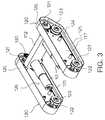
- FIG. 3is a perspective view of the mobile body unit included in the navigation means of FIG. 2;
- FIG. 4is a plan view of the navigation means provided in the apparatus of the invention shown in FIG. 2;
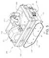
- FIG. 5is a perspective view of the apparatus of the invention from which the cover means is removed;
- FIG. 6is a plan view of the suction and collection means provided in the apparatus of the invention shown in FIG. 5;
- FIG. 7is a perspective view of the primary suction unit for the suction and collection means provided in the apparatus of the invention.
- FIG. 8is a bottom view of FIG. 7;
- FIG. 9is a schematic view of the primary collection unit for the suction and collection means provided in the apparatus of the invention.
- FIG. 10is an enlarged view of the circle A of FIG. 5 ;
- the remote-controlled mobile cleaning devicecomprises a navigation means 100 , a suction and collection means 200 , and a cover means 300 .
- the navigation means 100is a movable part of the device, which moves on a hot-cell floor with climbing over such obstacles as electrical cables and gas tubes placed on the floor.
- the suction and collection means 200 mounted on the navigation means 100dislodges, sucks, and captures radioactive waste debris.
- the cover means 300 mounted to the top of the suction and collection means 200protects the suction and collection means 200 from external impact or contaminants.
- the navigation means 100comprises a mobile body unit 110 carrying two drive motors 111 , two caterpillar units 120 provided at opposite sides of the mobile body unit 110 , and two bevel gear units 130 which connect the output shafts of the two drive motors 111 to the drive sprockets 121 .
- Each bevel gear unit 130comprises two bevel gears engaged with each other. Of the two bevel gears, the first one is fixed to the output shaft of an associated drive motor 111 , and the second one fixed to an associated drive sprocket 121 .
- the drive motor 111When the drive motor 111 is activated, the torque of the drive motor 111 is transmitted to the associated drive sprocket 121 connected to the associated caterpillar unit 120 through the associated bevel gear unit 130 , thus allowing the associated caterpillar unit 120 to be operated in conjunction with the associated drive motor 111 .
- the mobile body unit 110has two side support panels 117 at opposite sides thereof and holds each caterpillar unit 120 at the corresponding support panel 117 .
- Both a main support beam 112 and a front support beam 113are installed in parallel between the two side support panels 117 .
- the main support beam 112also supports the two drive motors 111 thereon. As shown in FIG.
- the body support plate 115 positioned at the end of the mobile body unit 110is mounted to the main support beam 112 using the locking bolts 114 at a certain height spaced apart from the surface of a hot-cell floor such that, when the navigation means 100 moves on the hot-cell floor, the body support plate 115 doesn't contact with the floor surface to be cleaned, thereby without contaminating the body support plate 115 with radioactive contaminants.
- a bracket 116having an installation opening, is mounted to the body support plate 115 and allows an electrical connector (not shown) to be installed on the mobile body unit 110 in order to supply power to the two drive motors 111 .
- the electrical connector (not shown) for the two drive motors 111can be installed on or removed from the mobile body unit 110 using a manipulator (not shown) in a remote manner.
- each caterpillar unit 120comprises a drive sprocket 121 , a driven sprocket 122 , a plurality of track guide rollers 123 , and a track 125 engaged with a chain 124 .
- the drive sprocket 121is mounted at a corner of an associated side support panel 117 and is rotated in conjunction with an associated drive motor 111 through an associated bevel gear unit 130 .
- the driven sprocket 122is mounted at another corner of the side support panel 117 in such a way that it is rotated and positioned on the same horizontal line as that of the drive sprocket 121 .
- a plurality of track guide rollers 123are provided at appropriate positions between the drive and driven sprockets 121 and 122 .
- the chain 124is wrapped around the drive and driven sprockets 121 and 122 while passing over the track guide rollers 123 .
- a series of teeth of the chain 124axially formed along the central axis of the inside surface of the track 125 , are engaged with the drive and driven sprockets 121 and 122 .
- Both sides of each caterpillar unit 120are also sealed with a protection plate 126 , thus protecting the drive sprocket 121 and the driven sprocket 122 , the track support rollers 123 , and the chain 124 from radioactive contaminants.
- Such arrangements of the caterpillar unit 120make the navigation means 100 possible to climb over such obstacles as electrical cables and pneumatic tubes placed on the hot-cell floor to be cleaned.
- the navigation means 100allows the cleaning device of this invention to carry out forward, reverse and steering movements. Such motions of the cleaning device are controlled by the velocity difference of the two driving motors 111 . By remote control from a control console (not shown) located outside the hot-cell the cleaning device moves to the desired cleaning location in-cell by activating the driving motors 111 .
- the suction and collection means 200 installed on the navigation means 100cleans and stores radioactive waste debris scattered on a hot-cell floor.
- the suction and collection means 200comprises a primary suction unit 210 , a flexible suction unit 230 , a primary collection unit 220 , a secondary collection unit 240 , a blower unit 250 , and a housing 260 .
- the primary suction unit 210 and the flexible suction unit 230are connected to the primary collection unit 220 which is also connected to the secondary collection unit 240 and a blower unit 250 in sequence.
- the primary suction unit 210dislodges and sucks radioactive waste debris placed on the surface of the hot-cell floor, while the primary collection unit 220 captures and stores the radioactive waste debris sucked by the primary suction unit 210 .
- the flexible suction unit 230is used to suck radioactive waste debris in areas to which the primary suction unit 210 can't access. More fine radioactive waste debris filtered from the primary collection unit 220 is also captured and stored by the secondary collection unit 240 which is connected to the blower unit 250 through a fourth pipe 280 .
- the blower unit 250generates suction force for sucking radioactive waste debris into the primary and secondary collection units 220 and 240 through the primary and flexible suction units 210 and 230 .
- the blower unit 250is held in its place within the housing 260 by a clamp 251 .
- a pipe connector(not shown), provided with a sealing ring (not shown), is set at each of the junctions between a first feed pipe 270 and the primary collection unit 220 , between a second feed pipe 271 and a third feed pipe 272 , and between a fourth feed pipe 280 and the blower unit 250 .
- Each connectorprevents an undesired leakage of the sucked radioactive waste debris or the contaminated air from the junctions during the operation of the cleaning device.
- the above-mentioned units comprising the suction and collection means 200are constructed in modules to allow remote operation and maintenance to be effected using manipulators or auxiliary tools (not shown) located inside the hot-cell, and they can be separated and assembled easily by remote manipulation.
- the primary suction unit 210 firmly fixed to the front bottom of the housing 260 by vertical supports 219consists of a brush roller 218 and a suction port 211 housing the brush roller 218 .
- the suction port 211is connected to the primary collection unit 220 through the first feed pipe 270 .
- the brush roller 218is made of a cylindrical bar 213 inserted with a bundle of thin bronze strings 216 in a double spiral shape.
- the driven gear 215mounted to the output shaft of the brush roller 218 , engages with the drive gear 214 mounted to the output shaft of the drive motor 212 , and thus the brush roller 218 is rotated by the torques of the drive motor 212 transmitted thereto through the two gears 214 and 215 .
- both soft and hard contaminated materials deposited on the hot-cell floorare dislodged by the rotation of the thin bronze strings 216 , and the vacuum provided by the blower unit 250 then effectively removes and collects them.
- Such arrangement of the brush roller 218 in conjunction with the blower unit 250improves the suction ability of the primary suction unit 210 .
- a fringe 217made of a bundle of thin bronze strings, is installed around the base of the suction port 211 in the form of a rectangle with opening in moving direction so that the suction port 211 can easily pass over obstacles placed on the hot-cell floor.
- the bottom end of the fringe 217 and the end of the bronze strings 216 of the brush roller 218are lined up so that they are always in contact with the floor surface during a cleaning operation.
- Such aligned fringe 217prevents the dislodged waste from spreading outside the suction port 211 .
- the flexible suction unit 230is used to clean up areas where the primary suction unit 210 is inaccessible or on surface of the equipment located inside the hot-cell.
- the flexible suction unit 230 connected to the primary collection unit 220comprises a suction nozzle 231 having a predetermined length, a flexible hose 232 extended from the suction nozzle 231 and connected to a control valve 234 , a connection horse 233 extended from the control valve 234 .
- the flexible hose 232is held around the outer sides of the housing 260 by a plurality of holders 261 .
- the control valve 234 fixed to the outer side of the housing 260is mounted at the junction between the flexible hose 232 and the connection horse 233 .
- the manipulator(not shown) in a remote manner grasps the suction nozzle 231 , removes it 231 from the holders 261 and guides it 231 to a desired cleaning position.
- the blower unit 250is then activated for cleaning after the control valve 234 is turned on using a manipulator (not shown).
- the primary collection unit 220comprises a storage case 221 that has a circular plate 2222 at the lower part by which the storage case 221 can sit on the interior of the housing 260 .
- a sealing cap 222includes a perforated conduit pipe 224 and a cylindrical ceramic filter 223 .
- the top end of the perforated conduit pipe 224is firmly fixed to the center hole of the sealing cap 222 and therefrom to the second feed pipe 271 .
- the cylindrical ceramic filter 223encircles the perforated conduit pipe 224 , and its top end is engaged with the sealing cap 222 at the depression 2221 with predetermined depth.
- the bottom end of the cylindrical ceramic filter 223is covered with a lower support member 225 that passes through the lower part of the perforated conduit pipe 224 .
- the bottom of the cylindrical ceramic filter 223 and the lower support member 225is tightly sealed by fastening a locking nut 226 through a thread 2241 made on the lower part of the perforated conduit pipe 224 , thereby making the ceramic filter 223 to be held below the sealing cap 222 .
- the ceramic filter 223 and the perforated conduit pipe 224are concentrically positioned with respect to the center hole of the sealing cap 222 .
- the sealing cap 222is installed on the top end of the storage case 221 and completely covers the storage case 221 by fastening a plurality of clamps 227 mounted on the upper outer surface of the storage case 221 .
- the storage case 221also has two connection ports 228 and 229 , of which the first one 228 is connected to the first feed pipe 270 of the primary suction unit 210 , while the second one 229 is connected to the connection hose 233 of the flexible suction unit 230 .
- the radioactive waste debriswhich is sucked either through the primary suction unit 210 or through the flexible suction unit 230 during the operation of the cleaning apparatus, is transmitted to the primary collection unit 220 through the first feed pipe 270 and is primarily filtered by the ceramic filter 223 .
- the waste debris filtered off by the ceramic filter 223is then effectively collected in the space made between the interior of the storage case 221 and the exterior of the ceramic filter 223 .
- Only a small amount of more fine waste debris filtered from the ceramic filter 223is introduced into the secondary collection unit 240 through both the second and third feed pipes 271 and 272 in sequence, and is then captured by the secondary collection unit 240 .
- the filtered air from the secondary collection unit 240is fed into the blower unit 250 through the fourth feed pipe 280 and then is exhausted into the atmosphere inside the hot-cell.
- the primary collection unit 220can be easily disassembled inside the hot-cell using a manipulator (not shown) in a remote manner.
- the primary collection unit 220can be also assembled with ease after transferring the radioactive waste debris collected in the storage case 221 to a waste drum for disposal. In such a way of collecting high radioactive waste and transferring it other depository, it is possible to identify the loss of nuclear spent fuel in the high radioactive material handling and treatment process by measuring the quantity of the collected radioactive waste debris.
- the secondary collection unit 240can be also exchanged for new one easily in a remote manner when necessary.
- the housing 260cases and supports the primary and flexible suction units 210 and 230 , the primary and secondary collection units 220 and 240 , and the blower unit 250 .
- An electrical connector(not shown) provided at the rear-wall of the housing 260 is used to remotely supply power to both the drive motor 212 of the primary suction unit 210 and the blower unit 250 .
- One side of the connection plate 290 mounted on the rear bottom of the housing 260is connected to the main support beam 112 of the navigation means 100 by a plurality of locking bolts 114 ′ that pass through the support plate 115 , shown in FIG. 2 .
- the bronze strings 216 of the brush roller 218 of the primary suction Unit 210are abraded for long use and fail to come into close contact with a floor surface to be cleaned, it needs to lower the ends of the bronze strings 216 downward.
- Such adjustmentcan be accomplished by controlling the housing 260 .
- An adjustable locking unit 140adjusts the height of the housing 260 so that the bronze strings 216 are always in contact with the hot-cell floor surface to be cleaned.
- the adjustable locking unit 140comprises an upper holder 144 , which is mounted on the front bottom of the housing 260 and has a downward channel.
- An adjustable bolt 142is set by a pin 145 within the downward channel of the upper holder 144 , thus enabling the adjustable bolt 142 to swing with respect to the pin 145 .
- an adjusting holder 141having upper and lower bosses with a horizontal channel defined between the two bosses, is horizontally mounted to the outer surface of the end support beam 113 .
- the adjustable bolt 142is also vertically held by the two bosses of the adjusting holder 141 , while a fan-shaped adjusting nut 143 , having an internally-threaded central opening, is engaged with the adjustable bolt 142 at a position between the two bosses of the adjusting holder 141 .
- the channel of the adjusting holder 141prevents the adjusting nut 143 from being unexpectedly removed from its desired horizontal position.
- the adjustable bolt 142 engaged with the upper holder 144primarily passes down through the upper boss of the adjusting holder 141 , and secondarily passes through the central opening of the adjusting nut 143 prior to being finally inserted into the lower boss of the adjusting holder 141 .
- the gap between the end of the bronze strings 216 of the brush roller 218 and the floor surface to be cleanedis controlled by rotating the fan-shaped adjusting nut 143 in a clockwise or counter-clockwise direction.
- Fastening the fan-shaped adjusting nut 143 engaged with the adjustable bolt 142 in a clockwise directionlowers down the housing 260 and the primary suction unit 210 relative to the hot-cell floor surface and makes the end of the bronze strings 216 to be in contact with the floor surface.
- the suction and collection means 200is assembled with the navigation means 100 by both the locking bolts 114 ′ at the rear and the adjustable locking unit 140 at the front When necessary, the suction and collection means 200 can be easily separated from the navigation means 100 by loosening both the locking bolts 114 ′ and the adjusting bolt 142 through remote manipulation.
- the navigation means 100 , the suction and collection means 200 , and the cover means 300are constructed in modules, which can be easily assembled and disassembled. Each module can be replaced with a new one easily by using a manipulator (not shown) in a remote manner when necessary.
- the present inventionprovides a remote-controlled mobile cleaning apparatus for use in a spent nuclear fuel process and fabrication area, such as a hot-cell, where humans are inaccessible due to the high radiation level of a spent nuclear fuel.
- the cleaning device of ties inventioncan dislodge, suck, collect, and remove the highly radioactive waste debris deposited both on the hot-cell floor and on the surface of the in-cell equipment. All functions for controlling the cleaning device of this invention remotely are contained within a control console (not shown) located outside the hot-cell.
- Such remote control for the cleaning devicemakes it possible for the human operator to be located at a safe, nonhazardous location nearby.
- the cleanup operations of the hot-cell contaminated with high radioactive materials using the cleaning device of this inventionhave the benefits of improved worker safety, increased facility soundness, and reduced personnel exposure dose rates.
Landscapes
- Engineering & Computer Science (AREA)
- Mechanical Engineering (AREA)
- Physics & Mathematics (AREA)
- General Engineering & Computer Science (AREA)
- High Energy & Nuclear Physics (AREA)
- Cleaning In General (AREA)
Abstract
Description
Claims (12)
Applications Claiming Priority (2)
| Application Number | Priority Date | Filing Date | Title |
|---|---|---|---|
| KR00-44768 | 2000-08-02 | ||
| KR10-2000-0044768AKR100391179B1 (en) | 2000-08-02 | 2000-08-02 | Teleoperated mobile cleanup device for highly radioactive fine waste |
Publications (2)
| Publication Number | Publication Date |
|---|---|
| US20020017005A1 US20020017005A1 (en) | 2002-02-14 |
| US6625843B2true US6625843B2 (en) | 2003-09-30 |
Family
ID=19681393
Family Applications (1)
| Application Number | Title | Priority Date | Filing Date |
|---|---|---|---|
| US09/863,444Expired - Fee RelatedUS6625843B2 (en) | 2000-08-02 | 2001-05-24 | Remote-controlled mobile cleaning apparatus for removal and collection of high radioactive waste debris in hot-cell |
Country Status (2)
| Country | Link |
|---|---|
| US (1) | US6625843B2 (en) |
| KR (1) | KR100391179B1 (en) |
Cited By (48)
| Publication number | Priority date | Publication date | Assignee | Title |
|---|---|---|---|---|
| US20060064844A1 (en)* | 2003-05-14 | 2006-03-30 | Venard Daniel C | Floating deck for use with a floor cleaning apparatus |
| USD533320S1 (en) | 2004-11-11 | 2006-12-05 | Castle Rock Industries, Inc. | Floor treatment device |
| US7188170B1 (en) | 2001-04-27 | 2007-03-06 | Blazent, Inc. | System for managing resources |
| US20080276407A1 (en)* | 2007-05-09 | 2008-11-13 | Irobot Corporation | Compact Autonomous Coverage Robot |
| US20090183337A1 (en)* | 2008-01-17 | 2009-07-23 | Davis Ronald E | Vacuum cleaner equipped with motor exhaust system |
| EP2258248A1 (en) | 2004-02-16 | 2010-12-08 | Karcher North America, Inc. | Apparatus for floor cleaning and treatment |
| US20110004339A1 (en)* | 2005-12-02 | 2011-01-06 | Irobot Corporation | Autonomous coverage robot navigation system |
| USD654234S1 (en) | 2010-12-08 | 2012-02-14 | Karcher North America, Inc. | Vacuum bag |
| US20120091070A1 (en)* | 2010-10-17 | 2012-04-19 | Bernard Sjauta | Multi-Stage Water Treatment and Enrichment Method and Apparatus |
| US8245345B2 (en) | 2003-05-14 | 2012-08-21 | Karcher North America, Inc. | Floor treatment apparatus |
| US8253368B2 (en) | 2004-01-28 | 2012-08-28 | Irobot Corporation | Debris sensor for cleaning apparatus |
| US8302240B2 (en) | 2009-07-29 | 2012-11-06 | Karcher North America, Inc. | Selectively adjustable steering mechanism for use on a floor cleaning machine |
| US8368339B2 (en) | 2001-01-24 | 2013-02-05 | Irobot Corporation | Robot confinement |
| US8374721B2 (en) | 2005-12-02 | 2013-02-12 | Irobot Corporation | Robot system |
| US8382906B2 (en) | 2005-02-18 | 2013-02-26 | Irobot Corporation | Autonomous surface cleaning robot for wet cleaning |
| US8386081B2 (en) | 2002-09-13 | 2013-02-26 | Irobot Corporation | Navigational control system for a robotic device |
| US8390251B2 (en) | 2004-01-21 | 2013-03-05 | Irobot Corporation | Autonomous robot auto-docking and energy management systems and methods |
| US8387193B2 (en) | 2005-02-18 | 2013-03-05 | Irobot Corporation | Autonomous surface cleaning robot for wet and dry cleaning |
| US8396592B2 (en) | 2001-06-12 | 2013-03-12 | Irobot Corporation | Method and system for multi-mode coverage for an autonomous robot |
| US8412377B2 (en) | 2000-01-24 | 2013-04-02 | Irobot Corporation | Obstacle following sensor scheme for a mobile robot |
| US8417383B2 (en) | 2006-05-31 | 2013-04-09 | Irobot Corporation | Detecting robot stasis |
| US8418303B2 (en) | 2006-05-19 | 2013-04-16 | Irobot Corporation | Cleaning robot roller processing |
| US8428778B2 (en) | 2002-09-13 | 2013-04-23 | Irobot Corporation | Navigational control system for a robotic device |
| US8463438B2 (en) | 2001-06-12 | 2013-06-11 | Irobot Corporation | Method and system for multi-mode coverage for an autonomous robot |
| US8474090B2 (en) | 2002-01-03 | 2013-07-02 | Irobot Corporation | Autonomous floor-cleaning robot |
| US8515578B2 (en) | 2002-09-13 | 2013-08-20 | Irobot Corporation | Navigational control system for a robotic device |
| USD693529S1 (en) | 2012-09-10 | 2013-11-12 | Karcher North America, Inc. | Floor cleaning device |
| US8584307B2 (en) | 2005-12-02 | 2013-11-19 | Irobot Corporation | Modular robot |
| US8594840B1 (en) | 2004-07-07 | 2013-11-26 | Irobot Corporation | Celestial navigation system for an autonomous robot |
| US8600553B2 (en) | 2005-12-02 | 2013-12-03 | Irobot Corporation | Coverage robot mobility |
| US8739355B2 (en) | 2005-02-18 | 2014-06-03 | Irobot Corporation | Autonomous surface cleaning robot for dry cleaning |
| US8780342B2 (en) | 2004-03-29 | 2014-07-15 | Irobot Corporation | Methods and apparatus for position estimation using reflected light sources |
| US8788092B2 (en) | 2000-01-24 | 2014-07-22 | Irobot Corporation | Obstacle following sensor scheme for a mobile robot |
| US8800107B2 (en) | 2010-02-16 | 2014-08-12 | Irobot Corporation | Vacuum brush |
| US8887340B2 (en) | 2003-05-14 | 2014-11-18 | Kärcher North America, Inc. | Floor cleaning apparatus |
| US8930023B2 (en) | 2009-11-06 | 2015-01-06 | Irobot Corporation | Localization by learning of wave-signal distributions |
| US8972052B2 (en) | 2004-07-07 | 2015-03-03 | Irobot Corporation | Celestial navigation system for an autonomous vehicle |
| US8978190B2 (en) | 2011-06-28 | 2015-03-17 | Karcher North America, Inc. | Removable pad for interconnection to a high-speed driver system |
| US9008835B2 (en) | 2004-06-24 | 2015-04-14 | Irobot Corporation | Remote control scheduler and method for autonomous robotic device |
| US9320398B2 (en) | 2005-12-02 | 2016-04-26 | Irobot Corporation | Autonomous coverage robots |
| US9326654B2 (en) | 2013-03-15 | 2016-05-03 | Irobot Corporation | Roller brush for surface cleaning robots |
| US10375880B2 (en) | 2016-12-30 | 2019-08-13 | Irobot Corporation | Robot lawn mower bumper system |
| EP3639718A1 (en) | 2018-10-17 | 2020-04-22 | Kärcher North America, Inc. | Wheel propelled steerable floor cleaning machine |
| USD907868S1 (en) | 2019-01-24 | 2021-01-12 | Karcher North America, Inc. | Floor cleaner |
| US11109727B2 (en) | 2019-02-28 | 2021-09-07 | Irobot Corporation | Cleaning rollers for cleaning robots |
| USD1016416S1 (en) | 2022-02-14 | 2024-02-27 | Karcher North America, Inc. | Floor cleaning machine |
| US12070181B2 (en) | 2017-05-04 | 2024-08-27 | Alfred Kärcher SE & Co. KG | Floor cleaning appliance and method for cleaning a floor surface |
| EP4427652A2 (en) | 2019-01-24 | 2024-09-11 | Kärcher North America, Inc. | Floor treatment apparatus |
Families Citing this family (25)
| Publication number | Priority date | Publication date | Assignee | Title |
|---|---|---|---|---|
| US8175890B2 (en)* | 2001-10-30 | 2012-05-08 | Biodose, Llc | Pharmacy based method and algorithm for handling of radioactive pharmaceuticals and generating of reports therefrom |
| US7630907B2 (en)* | 2001-10-30 | 2009-12-08 | Biodose, Llc | Algorithm and program for the handling and administration of radioactive pharmaceuticals |
| US20040039241A1 (en)* | 2002-05-29 | 2004-02-26 | Biodose Llc | Integrated distribution and communication process and algorithm for providing, handling, distributing or generating reports regarding radioactive pharmaceuticals |
| KR100577073B1 (en) | 2006-01-23 | 2006-05-04 | 주식회사 데콘엔지니어링 | Multifunctional Radioactive Pollution Distribution Remote Monitoring and Dust Collecting System |
| KR100605038B1 (en)* | 2006-02-07 | 2006-07-28 | 케이엔디티앤아이 주식회사 | Radioactive dust collector |
| KR100879774B1 (en)* | 2007-07-20 | 2009-01-21 | 한전케이피에스 주식회사 | Foreign body cleaning equipment around the reactor head |
| CA2674758C (en)* | 2009-07-30 | 2017-02-21 | G.B.D. Corp. | Surface cleaning apparatus |
| KR100967394B1 (en)* | 2009-10-29 | 2010-07-01 | 선광원자력안전(주) | A dry transaction equipment for radioactive concrete waste |
| KR101034870B1 (en)* | 2009-12-28 | 2011-05-17 | 고동욱 | Surge Discharge Grounding Device |
| KR100967396B1 (en) | 2010-03-24 | 2010-07-01 | 세안기술 주식회사 | A grinding automatic decontamination has a diffuse preventive funtion of raduation materiak |
| TWI455441B (en)* | 2010-12-06 | 2014-10-01 | Nat Univ Chin Yi Technology | Small reconnaissance device with direct methanol fuel cell |
| GB2494443B (en) | 2011-09-09 | 2013-08-07 | Dyson Technology Ltd | Autonomous surface treating appliance |
| CN110267068B (en)* | 2014-04-27 | 2021-11-02 | Lg电子株式会社 | Broadcast receiver and method thereof, and method and apparatus for transmitting broadcast signals |
| US20160198014A1 (en)* | 2015-01-05 | 2016-07-07 | Onavo Mobile Ltd. | Techniques for predictive network resource caching |
| KR102428780B1 (en)* | 2015-05-26 | 2022-08-03 | 엘지전자 주식회사 | Robot cleaner |
| CN105178228B (en)* | 2015-08-14 | 2016-08-24 | 宁波市江东明联物联科技有限公司 | Attending device is cleared up in a kind of low vibrations for bridge automatically |
| CN105064250B (en)* | 2015-08-14 | 2016-11-30 | 重庆泰吉机电设备有限公司 | A kind of pneumatic means be installed and automatically clear up attending device for bridge |
| CN105133525B (en)* | 2015-08-14 | 2017-01-04 | 南安市蒂巧工艺品有限公司 | A kind of pressure adjustable joint and for bridge automatically clear up attending device |
| JP6654973B2 (en)* | 2016-06-21 | 2020-02-26 | 日立Geニュークリア・エナジー株式会社 | Apparatus and method for preventing spread of radioactive material during recovery |
| CN106448786B (en)* | 2016-09-22 | 2024-12-10 | 北京轩宇智能科技有限公司 | Electrical interface equipment in hot chamber |
| KR102061287B1 (en) | 2018-04-17 | 2019-12-31 | 한국수력원자력 주식회사 | Dismantling and decontamination system and method of biodegradable concrete of pwr type nuclear power plant |
| CN110136859B (en)* | 2019-05-24 | 2023-12-22 | 中国人民解放军军事科学院国防工程研究院工程防护研究所 | Full-automatic radioactive dust recovery device capable of being paved and collected |
| KR102321590B1 (en)* | 2021-05-27 | 2021-11-04 | 세안에너텍 주식회사 | An exhaust treatment device for dust generated during radioactive wastes disposal at the operating or decommissioning nuclear power plant |
| CN114983271B (en)* | 2022-05-26 | 2024-07-12 | 首钢京唐钢铁联合有限责任公司 | Dust removing device |
| CN115059834A (en)* | 2022-06-27 | 2022-09-16 | 武汉铁路职业技术学院 | Emergency repair device for railway signal equipment |
Citations (8)
| Publication number | Priority date | Publication date | Assignee | Title |
|---|---|---|---|---|
| US4306329A (en)* | 1978-12-31 | 1981-12-22 | Nintendo Co., Ltd. | Self-propelled cleaning device with wireless remote-control |
| US5147002A (en)* | 1990-12-24 | 1992-09-15 | Container Products Corporation | Robotic decontamination apparatus |
| US5284522A (en)* | 1990-06-28 | 1994-02-08 | Matsushita Electric Industrial Co., Ltd. | Self-running cleaning control method |
| US5341540A (en)* | 1989-06-07 | 1994-08-30 | Onet, S.A. | Process and autonomous apparatus for the automatic cleaning of ground areas through the performance of programmed tasks |
| US5561883A (en)* | 1994-09-15 | 1996-10-08 | Landry; Kenneth C. | Tank cleaning system using remotely controlled robotic vehicle |
| US5787545A (en)* | 1994-07-04 | 1998-08-04 | Colens; Andre | Automatic machine and device for floor dusting |
| US5815880A (en)* | 1995-08-08 | 1998-10-06 | Minolta Co., Ltd. | Cleaning robot |
| US6119057A (en)* | 1997-03-21 | 2000-09-12 | Minolta Co., Ltd. | Autonomous vehicle with an easily set work area and easily switched mode |
Family Cites Families (2)
| Publication number | Priority date | Publication date | Assignee | Title |
|---|---|---|---|---|
| JPH11231096A (en)* | 1998-02-10 | 1999-08-27 | Ishikawajima Harima Heavy Ind Co Ltd | Clad recovery equipment |
| JP2000075082A (en)* | 1998-08-28 | 2000-03-14 | Ishikawajima Harima Heavy Ind Co Ltd | Underwater inspection equipment |
- 2000
- 2000-08-02KRKR10-2000-0044768Apatent/KR100391179B1/ennot_activeExpired - Fee Related
- 2001
- 2001-05-24USUS09/863,444patent/US6625843B2/ennot_activeExpired - Fee Related
Patent Citations (8)
| Publication number | Priority date | Publication date | Assignee | Title |
|---|---|---|---|---|
| US4306329A (en)* | 1978-12-31 | 1981-12-22 | Nintendo Co., Ltd. | Self-propelled cleaning device with wireless remote-control |
| US5341540A (en)* | 1989-06-07 | 1994-08-30 | Onet, S.A. | Process and autonomous apparatus for the automatic cleaning of ground areas through the performance of programmed tasks |
| US5284522A (en)* | 1990-06-28 | 1994-02-08 | Matsushita Electric Industrial Co., Ltd. | Self-running cleaning control method |
| US5147002A (en)* | 1990-12-24 | 1992-09-15 | Container Products Corporation | Robotic decontamination apparatus |
| US5787545A (en)* | 1994-07-04 | 1998-08-04 | Colens; Andre | Automatic machine and device for floor dusting |
| US5561883A (en)* | 1994-09-15 | 1996-10-08 | Landry; Kenneth C. | Tank cleaning system using remotely controlled robotic vehicle |
| US5815880A (en)* | 1995-08-08 | 1998-10-06 | Minolta Co., Ltd. | Cleaning robot |
| US6119057A (en)* | 1997-03-21 | 2000-09-12 | Minolta Co., Ltd. | Autonomous vehicle with an easily set work area and easily switched mode |
Cited By (143)
| Publication number | Priority date | Publication date | Assignee | Title |
|---|---|---|---|---|
| US8788092B2 (en) | 2000-01-24 | 2014-07-22 | Irobot Corporation | Obstacle following sensor scheme for a mobile robot |
| US8412377B2 (en) | 2000-01-24 | 2013-04-02 | Irobot Corporation | Obstacle following sensor scheme for a mobile robot |
| US8565920B2 (en) | 2000-01-24 | 2013-10-22 | Irobot Corporation | Obstacle following sensor scheme for a mobile robot |
| US8478442B2 (en) | 2000-01-24 | 2013-07-02 | Irobot Corporation | Obstacle following sensor scheme for a mobile robot |
| US9446521B2 (en) | 2000-01-24 | 2016-09-20 | Irobot Corporation | Obstacle following sensor scheme for a mobile robot |
| US8761935B2 (en) | 2000-01-24 | 2014-06-24 | Irobot Corporation | Obstacle following sensor scheme for a mobile robot |
| US9144361B2 (en) | 2000-04-04 | 2015-09-29 | Irobot Corporation | Debris sensor for cleaning apparatus |
| US9167946B2 (en) | 2001-01-24 | 2015-10-27 | Irobot Corporation | Autonomous floor cleaning robot |
| US9038233B2 (en) | 2001-01-24 | 2015-05-26 | Irobot Corporation | Autonomous floor-cleaning robot |
| US9622635B2 (en) | 2001-01-24 | 2017-04-18 | Irobot Corporation | Autonomous floor-cleaning robot |
| US9582005B2 (en) | 2001-01-24 | 2017-02-28 | Irobot Corporation | Robot confinement |
| US8368339B2 (en) | 2001-01-24 | 2013-02-05 | Irobot Corporation | Robot confinement |
| US8686679B2 (en) | 2001-01-24 | 2014-04-01 | Irobot Corporation | Robot confinement |
| US7188170B1 (en) | 2001-04-27 | 2007-03-06 | Blazent, Inc. | System for managing resources |
| US8396592B2 (en) | 2001-06-12 | 2013-03-12 | Irobot Corporation | Method and system for multi-mode coverage for an autonomous robot |
| US8463438B2 (en) | 2001-06-12 | 2013-06-11 | Irobot Corporation | Method and system for multi-mode coverage for an autonomous robot |
| US8838274B2 (en) | 2001-06-12 | 2014-09-16 | Irobot Corporation | Method and system for multi-mode coverage for an autonomous robot |
| US9104204B2 (en) | 2001-06-12 | 2015-08-11 | Irobot Corporation | Method and system for multi-mode coverage for an autonomous robot |
| US8656550B2 (en) | 2002-01-03 | 2014-02-25 | Irobot Corporation | Autonomous floor-cleaning robot |
| US8516651B2 (en) | 2002-01-03 | 2013-08-27 | Irobot Corporation | Autonomous floor-cleaning robot |
| US8671507B2 (en) | 2002-01-03 | 2014-03-18 | Irobot Corporation | Autonomous floor-cleaning robot |
| US8474090B2 (en) | 2002-01-03 | 2013-07-02 | Irobot Corporation | Autonomous floor-cleaning robot |
| US9128486B2 (en) | 2002-01-24 | 2015-09-08 | Irobot Corporation | Navigational control system for a robotic device |
| US8515578B2 (en) | 2002-09-13 | 2013-08-20 | Irobot Corporation | Navigational control system for a robotic device |
| US9949608B2 (en) | 2002-09-13 | 2018-04-24 | Irobot Corporation | Navigational control system for a robotic device |
| US8781626B2 (en) | 2002-09-13 | 2014-07-15 | Irobot Corporation | Navigational control system for a robotic device |
| US8428778B2 (en) | 2002-09-13 | 2013-04-23 | Irobot Corporation | Navigational control system for a robotic device |
| US8793020B2 (en) | 2002-09-13 | 2014-07-29 | Irobot Corporation | Navigational control system for a robotic device |
| US8386081B2 (en) | 2002-09-13 | 2013-02-26 | Irobot Corporation | Navigational control system for a robotic device |
| US9451861B2 (en) | 2003-05-14 | 2016-09-27 | Kärcher North America, Inc. | Floor treatment apparatus |
| US9730566B2 (en) | 2003-05-14 | 2017-08-15 | Kärcher North America, Inc. | Floor treatment apparatus |
| US9192276B2 (en) | 2003-05-14 | 2015-11-24 | Karcher North America, Inc. | Floor cleaning apparatus |
| US9015887B1 (en) | 2003-05-14 | 2015-04-28 | Kärcher North America, Inc. | Floor treatment apparatus |
| US8887340B2 (en) | 2003-05-14 | 2014-11-18 | Kärcher North America, Inc. | Floor cleaning apparatus |
| US10555657B2 (en) | 2003-05-14 | 2020-02-11 | Kärcher North America, Inc. | Floor treatment apparatus |
| US20060064844A1 (en)* | 2003-05-14 | 2006-03-30 | Venard Daniel C | Floating deck for use with a floor cleaning apparatus |
| US9757005B2 (en) | 2003-05-14 | 2017-09-12 | Kärcher North America, Inc. | Floor treatment apparatus |
| US9510721B2 (en) | 2003-05-14 | 2016-12-06 | Karcher North America, Inc. | Floor cleaning apparatus |
| US8438685B2 (en) | 2003-05-14 | 2013-05-14 | Karcher North America, Inc. | Floor treatment apparatus |
| US8528142B1 (en) | 2003-05-14 | 2013-09-10 | Karcher North America, Inc. | Floor treatment apparatus |
| US8245345B2 (en) | 2003-05-14 | 2012-08-21 | Karcher North America, Inc. | Floor treatment apparatus |
| US8749196B2 (en) | 2004-01-21 | 2014-06-10 | Irobot Corporation | Autonomous robot auto-docking and energy management systems and methods |
| US8461803B2 (en) | 2004-01-21 | 2013-06-11 | Irobot Corporation | Autonomous robot auto-docking and energy management systems and methods |
| US8390251B2 (en) | 2004-01-21 | 2013-03-05 | Irobot Corporation | Autonomous robot auto-docking and energy management systems and methods |
| US9215957B2 (en) | 2004-01-21 | 2015-12-22 | Irobot Corporation | Autonomous robot auto-docking and energy management systems and methods |
| US8854001B2 (en) | 2004-01-21 | 2014-10-07 | Irobot Corporation | Autonomous robot auto-docking and energy management systems and methods |
| US8378613B2 (en) | 2004-01-28 | 2013-02-19 | Irobot Corporation | Debris sensor for cleaning apparatus |
| US8253368B2 (en) | 2004-01-28 | 2012-08-28 | Irobot Corporation | Debris sensor for cleaning apparatus |
| US8598829B2 (en) | 2004-01-28 | 2013-12-03 | Irobot Corporation | Debris sensor for cleaning apparatus |
| US8456125B2 (en) | 2004-01-28 | 2013-06-04 | Irobot Corporation | Debris sensor for cleaning apparatus |
| DE202005022120U1 (en) | 2004-02-16 | 2014-03-24 | Karcher North America, Inc. | Device for soil cleaning and treatment |
| EP2820993A1 (en) | 2004-02-16 | 2015-01-07 | Kärcher North America, Inc. | Apparatus for floor cleaning and treatment |
| EP2820994A1 (en) | 2004-02-16 | 2015-01-07 | Kärcher North America, Inc. | Apparatus for floor cleaning and treatment |
| EP2258248A1 (en) | 2004-02-16 | 2010-12-08 | Karcher North America, Inc. | Apparatus for floor cleaning and treatment |
| US9360300B2 (en) | 2004-03-29 | 2016-06-07 | Irobot Corporation | Methods and apparatus for position estimation using reflected light sources |
| US8780342B2 (en) | 2004-03-29 | 2014-07-15 | Irobot Corporation | Methods and apparatus for position estimation using reflected light sources |
| US9486924B2 (en) | 2004-06-24 | 2016-11-08 | Irobot Corporation | Remote control scheduler and method for autonomous robotic device |
| US9008835B2 (en) | 2004-06-24 | 2015-04-14 | Irobot Corporation | Remote control scheduler and method for autonomous robotic device |
| US9229454B1 (en) | 2004-07-07 | 2016-01-05 | Irobot Corporation | Autonomous mobile robot system |
| US8634956B1 (en) | 2004-07-07 | 2014-01-21 | Irobot Corporation | Celestial navigation system for an autonomous robot |
| US8972052B2 (en) | 2004-07-07 | 2015-03-03 | Irobot Corporation | Celestial navigation system for an autonomous vehicle |
| US9223749B2 (en) | 2004-07-07 | 2015-12-29 | Irobot Corporation | Celestial navigation system for an autonomous vehicle |
| US8874264B1 (en) | 2004-07-07 | 2014-10-28 | Irobot Corporation | Celestial navigation system for an autonomous robot |
| US8594840B1 (en) | 2004-07-07 | 2013-11-26 | Irobot Corporation | Celestial navigation system for an autonomous robot |
| USD536146S1 (en) | 2004-11-11 | 2007-01-30 | Castle Rock Industries, Inc. | Floor treatment device |
| USD536846S1 (en) | 2004-11-11 | 2007-02-13 | Castle Rock Industries, Inc. | Floor treatment device |
| USD536845S1 (en) | 2004-11-11 | 2007-02-13 | Castle Rock Industries, Inc. | Floor treatment device |
| USD533320S1 (en) | 2004-11-11 | 2006-12-05 | Castle Rock Industries, Inc. | Floor treatment device |
| USD536843S1 (en) | 2004-11-11 | 2007-02-13 | Castle Rock Industries, Inc. | Floor treatment device |
| USD536842S1 (en) | 2004-11-11 | 2007-02-13 | Castle Rock Industries, Inc. | Floor treatment device |
| USD536844S1 (en) | 2004-11-11 | 2007-02-13 | Castle Rock Industries, Inc. | Floor treatment device |
| USD543323S1 (en) | 2004-11-11 | 2007-05-22 | Castle Rock Industries, Inc. | Floor treatment device |
| USD538492S1 (en) | 2004-11-11 | 2007-03-13 | Castle Rock Industries, Inc. | Floor treatment device |
| US8966707B2 (en) | 2005-02-18 | 2015-03-03 | Irobot Corporation | Autonomous surface cleaning robot for dry cleaning |
| US8670866B2 (en) | 2005-02-18 | 2014-03-11 | Irobot Corporation | Autonomous surface cleaning robot for wet and dry cleaning |
| US8392021B2 (en) | 2005-02-18 | 2013-03-05 | Irobot Corporation | Autonomous surface cleaning robot for wet cleaning |
| US8774966B2 (en) | 2005-02-18 | 2014-07-08 | Irobot Corporation | Autonomous surface cleaning robot for wet and dry cleaning |
| US10470629B2 (en) | 2005-02-18 | 2019-11-12 | Irobot Corporation | Autonomous surface cleaning robot for dry cleaning |
| US8855813B2 (en) | 2005-02-18 | 2014-10-07 | Irobot Corporation | Autonomous surface cleaning robot for wet and dry cleaning |
| US8387193B2 (en) | 2005-02-18 | 2013-03-05 | Irobot Corporation | Autonomous surface cleaning robot for wet and dry cleaning |
| US8382906B2 (en) | 2005-02-18 | 2013-02-26 | Irobot Corporation | Autonomous surface cleaning robot for wet cleaning |
| US8739355B2 (en) | 2005-02-18 | 2014-06-03 | Irobot Corporation | Autonomous surface cleaning robot for dry cleaning |
| US9445702B2 (en) | 2005-02-18 | 2016-09-20 | Irobot Corporation | Autonomous surface cleaning robot for wet and dry cleaning |
| US8985127B2 (en) | 2005-02-18 | 2015-03-24 | Irobot Corporation | Autonomous surface cleaning robot for wet cleaning |
| US8782848B2 (en) | 2005-02-18 | 2014-07-22 | Irobot Corporation | Autonomous surface cleaning robot for dry cleaning |
| US9320398B2 (en) | 2005-12-02 | 2016-04-26 | Irobot Corporation | Autonomous coverage robots |
| US8600553B2 (en) | 2005-12-02 | 2013-12-03 | Irobot Corporation | Coverage robot mobility |
| US8950038B2 (en) | 2005-12-02 | 2015-02-10 | Irobot Corporation | Modular robot |
| US8954192B2 (en) | 2005-12-02 | 2015-02-10 | Irobot Corporation | Navigating autonomous coverage robots |
| US8978196B2 (en) | 2005-12-02 | 2015-03-17 | Irobot Corporation | Coverage robot mobility |
| US10524629B2 (en) | 2005-12-02 | 2020-01-07 | Irobot Corporation | Modular Robot |
| US8661605B2 (en) | 2005-12-02 | 2014-03-04 | Irobot Corporation | Coverage robot mobility |
| US20110004339A1 (en)* | 2005-12-02 | 2011-01-06 | Irobot Corporation | Autonomous coverage robot navigation system |
| US8606401B2 (en) | 2005-12-02 | 2013-12-10 | Irobot Corporation | Autonomous coverage robot navigation system |
| US8374721B2 (en) | 2005-12-02 | 2013-02-12 | Irobot Corporation | Robot system |
| US8584305B2 (en) | 2005-12-02 | 2013-11-19 | Irobot Corporation | Modular robot |
| US8584307B2 (en) | 2005-12-02 | 2013-11-19 | Irobot Corporation | Modular robot |
| US9144360B2 (en) | 2005-12-02 | 2015-09-29 | Irobot Corporation | Autonomous coverage robot navigation system |
| US9149170B2 (en) | 2005-12-02 | 2015-10-06 | Irobot Corporation | Navigating autonomous coverage robots |
| US8761931B2 (en) | 2005-12-02 | 2014-06-24 | Irobot Corporation | Robot system |
| US9392920B2 (en) | 2005-12-02 | 2016-07-19 | Irobot Corporation | Robot system |
| US8380350B2 (en) | 2005-12-02 | 2013-02-19 | Irobot Corporation | Autonomous coverage robot navigation system |
| US9599990B2 (en) | 2005-12-02 | 2017-03-21 | Irobot Corporation | Robot system |
| US8418303B2 (en) | 2006-05-19 | 2013-04-16 | Irobot Corporation | Cleaning robot roller processing |
| US9955841B2 (en) | 2006-05-19 | 2018-05-01 | Irobot Corporation | Removing debris from cleaning robots |
| US10244915B2 (en) | 2006-05-19 | 2019-04-02 | Irobot Corporation | Coverage robots and associated cleaning bins |
| US9492048B2 (en) | 2006-05-19 | 2016-11-15 | Irobot Corporation | Removing debris from cleaning robots |
| US8528157B2 (en) | 2006-05-19 | 2013-09-10 | Irobot Corporation | Coverage robots and associated cleaning bins |
| US8572799B2 (en) | 2006-05-19 | 2013-11-05 | Irobot Corporation | Removing debris from cleaning robots |
| US8417383B2 (en) | 2006-05-31 | 2013-04-09 | Irobot Corporation | Detecting robot stasis |
| US9317038B2 (en) | 2006-05-31 | 2016-04-19 | Irobot Corporation | Detecting robot stasis |
| US8438695B2 (en) | 2007-05-09 | 2013-05-14 | Irobot Corporation | Autonomous coverage robot sensing |
| US9480381B2 (en) | 2007-05-09 | 2016-11-01 | Irobot Corporation | Compact autonomous coverage robot |
| US11072250B2 (en) | 2007-05-09 | 2021-07-27 | Irobot Corporation | Autonomous coverage robot sensing |
| US11498438B2 (en) | 2007-05-09 | 2022-11-15 | Irobot Corporation | Autonomous coverage robot |
| US10070764B2 (en) | 2007-05-09 | 2018-09-11 | Irobot Corporation | Compact autonomous coverage robot |
| US8370985B2 (en) | 2007-05-09 | 2013-02-12 | Irobot Corporation | Compact autonomous coverage robot |
| US8347444B2 (en) | 2007-05-09 | 2013-01-08 | Irobot Corporation | Compact autonomous coverage robot |
| US10299652B2 (en) | 2007-05-09 | 2019-05-28 | Irobot Corporation | Autonomous coverage robot |
| US8239992B2 (en)* | 2007-05-09 | 2012-08-14 | Irobot Corporation | Compact autonomous coverage robot |
| US8726454B2 (en) | 2007-05-09 | 2014-05-20 | Irobot Corporation | Autonomous coverage robot |
| US20080276407A1 (en)* | 2007-05-09 | 2008-11-13 | Irobot Corporation | Compact Autonomous Coverage Robot |
| US20090183337A1 (en)* | 2008-01-17 | 2009-07-23 | Davis Ronald E | Vacuum cleaner equipped with motor exhaust system |
| US8302240B2 (en) | 2009-07-29 | 2012-11-06 | Karcher North America, Inc. | Selectively adjustable steering mechanism for use on a floor cleaning machine |
| US8930023B2 (en) | 2009-11-06 | 2015-01-06 | Irobot Corporation | Localization by learning of wave-signal distributions |
| US11058271B2 (en) | 2010-02-16 | 2021-07-13 | Irobot Corporation | Vacuum brush |
| US10314449B2 (en) | 2010-02-16 | 2019-06-11 | Irobot Corporation | Vacuum brush |
| US8800107B2 (en) | 2010-02-16 | 2014-08-12 | Irobot Corporation | Vacuum brush |
| US20120091070A1 (en)* | 2010-10-17 | 2012-04-19 | Bernard Sjauta | Multi-Stage Water Treatment and Enrichment Method and Apparatus |
| USD654234S1 (en) | 2010-12-08 | 2012-02-14 | Karcher North America, Inc. | Vacuum bag |
| US8978190B2 (en) | 2011-06-28 | 2015-03-17 | Karcher North America, Inc. | Removable pad for interconnection to a high-speed driver system |
| USD693529S1 (en) | 2012-09-10 | 2013-11-12 | Karcher North America, Inc. | Floor cleaning device |
| US10292560B2 (en) | 2013-03-15 | 2019-05-21 | Irobot Corporation | Roller brush for surface cleaning robots |
| US9326654B2 (en) | 2013-03-15 | 2016-05-03 | Irobot Corporation | Roller brush for surface cleaning robots |
| US10375880B2 (en) | 2016-12-30 | 2019-08-13 | Irobot Corporation | Robot lawn mower bumper system |
| US12070181B2 (en) | 2017-05-04 | 2024-08-27 | Alfred Kärcher SE & Co. KG | Floor cleaning appliance and method for cleaning a floor surface |
| EP3639718A1 (en) | 2018-10-17 | 2020-04-22 | Kärcher North America, Inc. | Wheel propelled steerable floor cleaning machine |
| USD907868S1 (en) | 2019-01-24 | 2021-01-12 | Karcher North America, Inc. | Floor cleaner |
| EP4427652A2 (en) | 2019-01-24 | 2024-09-11 | Kärcher North America, Inc. | Floor treatment apparatus |
| US11109727B2 (en) | 2019-02-28 | 2021-09-07 | Irobot Corporation | Cleaning rollers for cleaning robots |
| US11871888B2 (en) | 2019-02-28 | 2024-01-16 | Irobot Corporation | Cleaning rollers for cleaning robots |
| US12239279B2 (en) | 2019-02-28 | 2025-03-04 | Irobot Corporation | Cleaning rollers for cleaning robots |
| USD1016416S1 (en) | 2022-02-14 | 2024-02-27 | Karcher North America, Inc. | Floor cleaning machine |
Also Published As
| Publication number | Publication date |
|---|---|
| KR100391179B1 (en) | 2003-07-12 |
| KR20020011485A (en) | 2002-02-09 |
| US20020017005A1 (en) | 2002-02-14 |
Similar Documents
| Publication | Publication Date | Title |
|---|---|---|
| US6625843B2 (en) | Remote-controlled mobile cleaning apparatus for removal and collection of high radioactive waste debris in hot-cell | |
| CA2510549C (en) | A cleaning and/or inspecting robot for hazardous environments including catalyst removal | |
| EP2306467B1 (en) | Method of capturing material during dry ice blasting | |
| JPH05507557A (en) | Decontamination methods and equipment for radioactively contaminated surfaces | |
| CN112489845A (en) | Laser decontamination and recovery device for plate type heat exchange fins of PTR (thermal transport resistor) system of nuclear power station | |
| CN112775113A (en) | Irradiation-resistant laser cleaning and dust collecting robot and operation method | |
| KR101967107B1 (en) | Automatic Blasting Decontamination System | |
| JP2013163226A (en) | Blast decontamination system and blast application method using the system | |
| US20210257120A1 (en) | Device for Deactivating Radioactive Elements | |
| KR830002114B1 (en) | How to remove contaminants | |
| KR830002574B1 (en) | Contaminant Removal Device | |
| JP2002311191A (en) | Decontamination equipment for radioactive decontamination | |
| KR101590982B1 (en) | Movable automatic radioactive decontamination apparatus and radioactive decontamination system using the same | |
| US5749470A (en) | Installation for decontaminating a radioactively contaminated surface | |
| KR102201851B1 (en) | Pipe shielding apparatus and pipe decontamination method using the same | |
| CN112599276B (en) | Nuclear power plant radioactive waste filter element carrying device | |
| JP6518511B2 (en) | Method of opening reactor pressure vessel and method of taking out fuel debris | |
| JP3785748B2 (en) | Laser processing equipment | |
| JP7241044B2 (en) | Guide device and method for work equipment, work equipment and method for collecting radioactive waste | |
| CN112331377B (en) | LIBS-based automatic radionuclide removal method | |
| CA2521475C (en) | Construction implement for granular bed regeneration | |
| KR102201852B1 (en) | Pipe decontamination apparatus, pipe decontamination system including the same and pipe decontamination method using the same | |
| KR100478790B1 (en) | Remote contamination cleaning robot | |
| JPH0752639Y2 (en) | Reactor pressure vessel flange sheet cleaning and inspection device | |
| JPS60260898A (en) | Washer for drive of control rod for nuclear reactor |
Legal Events
| Date | Code | Title | Description |
|---|---|---|---|
| AS | Assignment | Owner name:KOREA ATOMIC ENERGY RESEARCH INSTITUTE, KOREA, REP Free format text:ASSIGNMENT OF ASSIGNORS INTEREST;ASSIGNORS:HO-KI, KIM;JANG-JIN, PARK;MYUNG-SEUNG, YANG;AND OTHERS;REEL/FRAME:011839/0374 Effective date:20010426 Owner name:KOREA ELECTRIC POWER CORPORATION, KOREA, REPUBLIC Free format text:ASSIGNMENT OF ASSIGNORS INTEREST;ASSIGNORS:HO-KI, KIM;JANG-JIN, PARK;MYUNG-SEUNG, YANG;AND OTHERS;REEL/FRAME:011839/0374 Effective date:20010426 | |
| FEPP | Fee payment procedure | Free format text:PAYOR NUMBER ASSIGNED (ORIGINAL EVENT CODE: ASPN); ENTITY STATUS OF PATENT OWNER: LARGE ENTITY | |
| FPAY | Fee payment | Year of fee payment:4 | |
| FPAY | Fee payment | Year of fee payment:8 | |
| AS | Assignment | Owner name:KOREA HYDRO & NUCLEAR POWER CO., LTD., KOREA, REPU Free format text:ASSIGNMENT OF ASSIGNORS INTEREST;ASSIGNOR:KOREA ELECTRIC POWER CORPORATION;REEL/FRAME:027847/0366 Effective date:20110930 | |
| REMI | Maintenance fee reminder mailed | ||
| LAPS | Lapse for failure to pay maintenance fees | ||
| STCH | Information on status: patent discontinuation | Free format text:PATENT EXPIRED DUE TO NONPAYMENT OF MAINTENANCE FEES UNDER 37 CFR 1.362 | |
| FP | Lapsed due to failure to pay maintenance fee | Effective date:20150930 |