US6625563B2 - Gain factor and position determination system - Google Patents
Gain factor and position determination systemDownload PDFInfo
- Publication number
- US6625563B2 US6625563B2US09/892,153US89215301AUS6625563B2US 6625563 B2US6625563 B2US 6625563B2US 89215301 AUS89215301 AUS 89215301AUS 6625563 B2US6625563 B2US 6625563B2
- Authority
- US
- United States
- Prior art keywords
- magnetic field
- orientation
- determining
- gain factor
- probe
- Prior art date
- Legal status (The legal status is an assumption and is not a legal conclusion. Google has not performed a legal analysis and makes no representation as to the accuracy of the status listed.)
- Expired - Lifetime
Links
Images


Classifications
- G—PHYSICS
- G01—MEASURING; TESTING
- G01V—GEOPHYSICS; GRAVITATIONAL MEASUREMENTS; DETECTING MASSES OR OBJECTS; TAGS
- G01V3/00—Electric or magnetic prospecting or detecting; Measuring magnetic field characteristics of the earth, e.g. declination, deviation
- G01V3/08—Electric or magnetic prospecting or detecting; Measuring magnetic field characteristics of the earth, e.g. declination, deviation operating with magnetic or electric fields produced or modified by objects or geological structures or by detecting devices
- G01V3/081—Electric or magnetic prospecting or detecting; Measuring magnetic field characteristics of the earth, e.g. declination, deviation operating with magnetic or electric fields produced or modified by objects or geological structures or by detecting devices the magnetic field is produced by the objects or geological structures
- A—HUMAN NECESSITIES
- A61—MEDICAL OR VETERINARY SCIENCE; HYGIENE
- A61B—DIAGNOSIS; SURGERY; IDENTIFICATION
- A61B5/00—Measuring for diagnostic purposes; Identification of persons
- A61B5/06—Devices, other than using radiation, for detecting or locating foreign bodies ; Determining position of diagnostic devices within or on the body of the patient
- A61B5/061—Determining position of a probe within the body employing means separate from the probe, e.g. sensing internal probe position employing impedance electrodes on the surface of the body
- A61B5/062—Determining position of a probe within the body employing means separate from the probe, e.g. sensing internal probe position employing impedance electrodes on the surface of the body using magnetic field
Definitions
- This inventionrelates to systems that use magnetic fields to determine an object's location and orientation, and system gain factor.
- systemsmay use magnetic field measurements to indirectly determine the location and orientation of an object. These systems are useful, for example, in the medical field, because they are able to accurately locate an object in a patient's body with only minimal intrusion into the body.
- the intrusioninvolves placing a small probe near the object to be located.
- the three-dimensional location and orientation of the probeis then determined from the effect that the probe's location and orientation have on magnetic field measurements.
- the probemay be either a source or a sensor of a magnetic field. If the probe is a source, sensors exterior to the body measure the field produced by the probe. If the probe is a sensor, magnetic sources exterior to the body produce the fields being measured.
- Determining a probe's location and orientation from magnetic field measurementsis not straight forward because the measured magnetic fields are nonlinear functions of the location and orientation.
- the probe's location and orientationare first presumed or “guessed” to be at a predicted location and orientation.
- An iterative processis used to compare values of the magnetic field at the guessed probe location and orientation with the measured field values. If the magnetic field values at a guessed location and orientation are close to the measured values, the guessed location and orientation are presumed to accurately represent the actual location and orientation of the probe.
- the iterative processuses a physical model for the probe's environment.
- the physical modelspecifies the location and orientation of each field source. From the specified locations and orientations, laws of electrodynamics determine the field values.
- the probe and its positioning systemare physical systems, they are susceptible to various external influences (e.g., stray magnetic fields, field absorbing materials being positioned proximate the field generators and/or sensors, etc.) that affect the gain of the system. Additionally, these physical devices have various engineering tolerances (e.g., cable resistance, probe gain, input impedance, etc.) that also affect overall system gain. Accordingly, each time a component of the system is replaced, the system must be manually recalibrated.
- a system for determining the position, orientation and system gain factor of a probeincludes magnetic field sources and at least one magnetic field sensor, such that a combination of a magnetic field sensor and a magnetic field source generates a unique measured magnetic field value.
- the systemalso includes a probe whose position and orientation affect the unique measured magnetic field values.
- a processorcoupled to receive these unique measured magnetic field values, iteratively processes measured magnetic field values to determine a system gain factor indicative of the gain of the probe and location factors indicative of the position and orientation of the probe.
- the number of unique measured magnetic field values generatedmust be at least equal to the sum of the number of factors calculated.
- the iterative processis configured to determine a function of the differences between the measured magnetic field values and a plurality of predicted magnetic field values.
- the processorincludes a calculated location process for calculating the predicted magnetic field values, in that the calculated location process guesses an initial gain, position and orientation for the probe, and then calculates the predicted magnetic field values based on a physical model and the initial gain, position and orientation.
- the initial position and orientationmay be a predetermined or randomly selected fixed point.
- the processorincludes an optimization function for determining an extremum indicative of the differences between the measured magnetic field values and the predicted magnetic field values.
- the optimization functionis a least squares sum function.
- the processorincludes a repositioning process for adjusting the initial gain, position and orientation of the probe in response to the extremum being in a predefined range of unacceptable values, which is indicative of an unacceptable level of difference between the measured magnetic field values and the plurality of predicted magnetic field values.
- the location factorsmay include spatial, spherical, and/or rotational coordinates.
- a method for determining the position, orientation and system gain factor of a three-dimensional objectincludes positioning a plurality of magnetic field sources proximate the three-dimensional object and positioning at least one magnetic field sensor in a fixed spatial relationship with that three-dimensional object. A combination of a magnetic field sensor and a magnetic field source generates a unique measured magnetic field value. Further, the position and orientation of the three-dimensional object affects these unique measured magnetic field values. The method determines a system gain factor indicative of the gain of the three-dimensional object and a plurality of location factors indicative of the position and orientation of the three-dimensional object. The number of unique measured magnetic field values generated must be at least equal to the sum of the number of factors calculated.
- the step of determining a system gain factor and a plurality of location factorsincludes determining a function of the differences between the measured magnetic field values and a plurality of predicted magnetic field values.
- the step of determining a system gain factor and a plurality of location factorsincludes guessing an initial gain, position and orientation for the three-dimensional object and calculating the predicted magnetic field values based on a physical model and the initial gain, position and orientation.
- the step of determining a system gain factor and a plurality of location factorsincludes determining an extremum indicative of the differences between the measured magnetic field values and the predicted magnetic field values.
- the step of determining a system gain factor and a plurality of location factorsincludes adjusting the initial gain, position, and orientation of the three-dimensional object in response to the extremum being in a predefined range of unacceptable values, which is indicative of an unacceptable level of difference between the measured magnetic field values and the plurality of predicted magnetic field values.
- system and method described aboveincludes a plurality of magnetic field sources and at least one magnetic field sensor
- systemcan also include a plurality of magnetic field sensors and at least one magnetic field source.
- probecan actually be any three-dimensional object, such as a hollow tube (e.g., a biopsy needle).
- FIG. 1is a schematic representation of a system that uses magnetic measurements to find a probe's system gain factor, location, and orientation;
- FIG. 2is a perspective view of the system of FIG. 1;
- FIG. 3is a side view of an alternate system that uses magnetic measurements to find a probe's gain, location, and orientation;
- FIG. 4is a flow chart for a process that iteratively guesses the gain, location, and orientation of a probe from measured magnetic field values
- FIG. 5is a flow chart for a process that determines whether the best guess of the gain, location, and orientation of a probe is reliable
- FIG. 6is a flow chart for a process that evaluates an error or optimization function at global and local extrema
- FIG. 7is a flow chart for a process that determines extrema values of the error or optimization function that correspond to the presence of distortions.
- FIG. 8shows a computer that finds a probe's gain, location, and orientation from measurements of magnetic fields.
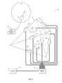
- FIGS. 1 and 2there is shown a schematic representation of a system 10 that uses measurements of magnetic fields to find the location, orientation and system gain factor of a moveable probe 12 .
- the moveable probe 12is located inside a volume 14 (e.g., a body of a medical patient).
- System 10also includes a plurality of field sources 16 1 ⁇ n (e.g., small induction coils) that are located outside of volume 14 .
- Field sources 16are driven by a field-generating module 22 (e.g., an alternating or direct current source). Please note that while seven field sources are shown, this is for illustrative purposes only and is not intended to be a limitation of the invention.
- FIG. 2is a side view of system 10 that shows the three-dimensional orientation and location of field sources 16 1 ⁇ n and probe 12 .
- Each field source 16 1 ⁇ nis either: a surface-mount field source 17 located on a surface 18 of a regular tetrahedron 24 ; or an edge-mount field source 19 located on an edge 20 of a regular tetrahedron 24 .
- the field sources 16 1 ⁇ nare typically oriented so that their internal magnetic moments “m” are either perpendicular to the surfaces 18 of tetrahedron 24 or parallel to the edges 20 of tetrahedron 24 .
- Probe 12is located outside of tetrahedron 24 and has an orientation defined by a normal direction “n” to a sensor 13 that measures local magnetic field values.
- Sensor 13may include a simple coil, several coils, a Hall sensor, or a flux gate sensor and may measure a magnetic field flux or magnetic field differential.
- system 10is shown to include a single tetrahedron 24 having a maximum of four surface-mount field sources 17 and six edge-mount field sources 19 , this is for illustrative purposes only and is not intended to be a limitation of the invention, as the positioning of these field sources 16 1 ⁇ n can be adjusted and reconfigured as known by those skilled in the art.
- a pair of tetrahedrons 24 utilizing only edge-mount field sources 19can be utilized. This configuration allows for a maximum of twelve distinct field sources.
- Each source 16 1 ⁇ nmay also include single or multiple field coils.
- the magnetic field in the volume 14can be approximated by a dipole field.
- the magnetic field in the volume 14may be a higher multipole field.
- each source 16 1 ⁇ nuses two identical coils whose normal vectors are anti-parallel. Such a source produces a magnetic quadrapole field in volume 14 .
- a quadrapole fieldhas larger spatial variations than a dipole field and thus, may be more convenient for locating probe 12 .
- field sources 16 1 ⁇ nmay use field sources 16 1 ⁇ n that primarily generate higher magnetic multipole fields. Further, other embodiments may use a different numbers of field sources 16 1 ⁇ n or locate and orient the field sources 16 1 ⁇ n differently.
- EMF'selectromotive forces
- An electronics module 26 connected to probe 12measures the EMF's.
- the measured EMF'srepresent the measured local values of magnetic fields at the probe's location and orientation in space 14 .
- Electronics module 26also can identify the individual source 16 1 ⁇ n that produces each measured EMF.
- measurement timing informationis used to identify the source 16 1 ⁇ n producing a measured field.
- field-generating module 22temporally multiplexes power to the different field sources 16 1 ⁇ n and relays timing information to the electronics module 26 .
- the field generating module 22drives each field source 16 1 ⁇ n at a different frequency.
- electronics module 26 or computer 28decomposes measured EMF's from the probe's coil 13 into frequency components. These frequency components of the measured fields are then matched to individual field sources 16 ⁇ n .
- electronics module 26outputs several measured magnetic fields B 1 ⁇ n measured corresponding to the individual field measurements performed. It is important to note that there are several hardware configurations that can generate these field measurements. For example, if eight distinct field measurements are desired, system 10 can be configured so that eight field sources 16 1 ⁇ n are utilized in conjunction with a probe 12 incorporating one sensor coil 13 . In this configuration sensor coil 13 would measure the field generated by each of the eight field sources 16 1 ⁇ n resulting in eight distinct field measurements.
- a probe 12could be constructed that incorporates multiple sensor coils 13 .
- this configurationwould double the number of individual field measurements achievable by that probe (using the equivalent number of field sources 16 1 ⁇ n ).
- each coilcould independently measure the strength of the magnetic field generated by a single field source. Therefore, if (as stated above) eight distinct field measurements are desired and a probe 12 is utilized that includes two sensor coils 13 , only four field sources 16 1 ⁇ n would be required, as each coil 13 could independently measure the field generated by each of the four field sources, thus resulting in eight distinct field measurements.
- measured magnetic field values B 1 ⁇ n measureddepend on the system gain factor of probe 12 and the three-dimensional location and the orientation of the probe's coil 13 . Please note that the lower case “n” is used to denote the number of measured magnetic fields (except where it denotes normal vectors in the various figures).
- system 10will determine the system gain factor of probe 12 . Additionally, system 10 will also determine the position and orientation of probe 12 . As the position and orientation of probe 12 is described by specifying up to six degrees of freedom (i.e., x-axis position, y-axis position, z-axis position, roll, pitch, and yaw) for probe 12 , the maximum number of position factors that system 10 will calculate is six. Therefore, the maximum number of factors (both positional and gain) that system 10 calculates is seven.
- the number of distinct field measurements required to determine these factorsis one greater than the number of factors being determined. Accordingly, if system 10 is determining the system gain factor plus six positional factors (i.e., degrees of freedom), a total of seven calculated factors need to be determined. This would require eight distinct field measurements. As stated above, this can be achieved utilizing a probe 12 incorporating a single sensor coil 13 and eight field sources 16 1 ⁇ n . Alternatively, this could be achieved by utilizing a probe 12 incorporating eight sensor coils 13 (if physically possible) and only one field source 16 1 ⁇ n . Accordingly, the important issue is the number of distinct field measurements made and not the specific number of field source 16 1 ⁇ n or sensor coils 13 employed.
- system 10is determining the system gain factor plus five positional factors (i.e., five degrees of freedom), a total of six calculated factors need to be determined. Again, as above, this can be accomplished utilizing a variety of configurations.
- the use of a number of distinct field measurements that is greater than the number of factors being calculatedallows for the determination of the quality of the guesses used during an iterative process. If this quality determination is not required (or desired), the specific number of distinct field measurement required would be equal to the number of factors being calculated.
- the system gain factoractually consists of two components, namely a gain factor for each sensor within the probe. Accordingly, the total number of calculated factors is eight (six positional, the gain factor for the first field sensor, and the gain factor for the second field sensor) and, therefore, the number of distinct field measurements required is nine (if the quality determination is required or desired).
- Electronics module 26sends the measured field values to computer 28 .
- Computer 28uses the measured magnetic field values to determine the probe's system gain factor and location/orientation by comparing the measured magnetic field values to magnetic field values from a physical model, as will be described below in greater detail.
- the physical modelis a set of physical equations that determine values of magnetic fluxes measured by probe 12 as a function of several parameters.
- the parametersinclude: the position, orientation, and magnetic moments of field sources 16 1 ⁇ n ; the location, orientation, and sensitivity of probe 12 ; and characteristics of electronics module 26 .
- a vector (x, y, z) and a pair of angles ( ⁇ , ⁇ )specify the three-dimensional location and orientation of sensor coil 13 of probe 12 . If the probe 12 has multiple non-colinear coils, the parameters may include an additional angular parameter ( ⁇ ) that defines a rotational aspect of the probe 12 .
- this factor(i.e., the sixth degree of freedom) can only be calculated by utilizing a probe having a second coil on a different axis (non-coaxial), as multiple coils about the same axis would not allow system 10 to sense probe rotation about that axis.
- each sourcemay describe each source as a magnetic multipole so that the fields measured by sensor coil 13 are the associated multipole fields (e.g., dipole or quadrapole).
- the multipole field valuesdepend on the system gain and the location, orientation, and magnetic moment “m” of each source 16 1 ⁇ n .
- the measured values of the magnetic fluxdepend on the location, size, orientation and gain of sensor coil 13 with respect to field sources 16 1 ⁇ n .
- the physical modelis also based on underlying assumptions about the environment near the volume 14 . For example, the model assumes preselected values for the location and orientation of each field source 16 1 ⁇ n and the absence of other sources or field distorting objects. The presence of field distorting objects 30 , 32 (e.g., conductors or new field sources) may invalidate the model's predictions for field values. However, the negative effects of constant background fields are eliminated, as sensing coil 13 only measures time varying magnetic fields. Alternatively, if static field measurements are desired, a flux gate sensor or hall effect sensor (as is known in the art) can be utilized, as they allow for measurement of static (or constant) magnetic fields.
- a flux gate sensor or hall effect sensoras is known in the art
- FIG. 3shows another system 40 that uses magnetic measurements to find the system gain factor and location/orientation of a moveable probe 42 .
- the movable probe 42which is located inside an observation volume 44 , is a source of a magnetic field and external field sensors 46 1 ⁇ n measure the magnetic field produced by probe 42 .
- Probe 42connects to a field-generating module 51 (e.g., a voltage source).
- these field sensors 46 1 ⁇ nwhich are located on either the edges or surfaces of a tetrahedron 41 , measure either magnetic fields or magnetic field gradients through induced EMF's.
- Each sensor 46 1 ⁇ nmay have one or more magnetic field sensors oriented to measure fields in various directions.
- Each sensor 46 1 ⁇ nhas an orientation “p” fixed by the orientation of its one or more internal magnetic field sensors.
- each sensormay vary depending on the specific application and the number of factors (i.e., position/orientation and system gain) being determined.
- An electronics module 52monitors EMF's from the various field sensors 46 1 ⁇ n to determine the individual magnetic field values. These measured magnetic field values are then sent to a computer 54 , which calculates the system gain factor and location/orientation of the probe 42 from these measured magnetic field values.
- both systems 10 , 40measure a set of magnetic fluxes to obtain a set of measured magnetic field values B 1 ⁇ n measured , such that “n” is greater than the number of factors (i.e., position and system gain) being calculated.
- This set of measured field values B 1 ⁇ n measuredwhich are obtained from measured magnetic fluxes, also has a non-linear dependence on the three-dimensional location/orientation of the probe and a linear dependence on the system gain factor.
- the probe's location and orientationare defined by a vector (x, y, z) and at least a pair of azimuthal and polar angles ( ⁇ , ⁇ ), respectively.
- the system gain factor of probe 12is defined by a gain coefficient (g).
- the physical modeldescribes a preselected magnetic environment in the region of the field sensor[s] (i.e., the volumes 14 and 44 shown in FIGS. 1 and 3 respectively).
- the preselected magnetic environmentmay or may not include contributions from nearby conducting objects (i.e., objects 30 and 32 ). If the preselected environment is different from the actual environment, the model may predict incorrect magnetic field values; otherwise the predictions are correct.
- the actual environmentmay be different due to the presence of field distorting objects 30 , 32 .
- Field distorting objects 30 , 32include conducting objects that support eddy currents (e.g., a pair of surgical scissors, ferromagnetic materials, and active sources of magnetic fields). The presence of such objects can invalidate magnetic determinations of the probe's gain, location, and orientation.
- the iterative processmay also yield incorrect probe gain, location, and orientation because of hardware or software failures in modules 22 , 26 , 51 , 52 or computers 28 , 54 .
- each system 10 , 40detects and warns users about the presence of potentially measurement distorting conditions (e.g., by flashing messages on a video monitor or through audio alert signals).
- Probe 12can be various other devices known in the art (e.g., a catheter, an endoscope, biopsy needles, body-mounted position sensors, etc.).
- FIG. 4shows a flow chart for an iterative process 60 that uses the measured magnetic field values B 1 ⁇ n measured to determine the gain, location, and orientation of either probe 12 of FIGS. 1-2 or probe 42 of FIG. 3 .
- Process 60receives 62 an initial guess for the probe's system gain factor, location and orientation.
- This initial guesscan be predefined in the process, user definable, or randomly selected.
- the initial guessis a preselected point of the (x, y, z, ⁇ , ⁇ ) parameter space that defines the location and orientation of the probe and a preselected system gain factor (g).
- the initial guessis the first accepted guess for the probe's gain, location, and orientation. From the last accepted guess, the process makes a new guess 64 for the probe's location, orientation, and gain.
- the initial preselected point (x, y, z, ⁇ , ⁇ )is shown to include five degrees of freedom, this is for illustrative purposes only and is not intended to be a limitation of the invention. Specifically, if greater or fewer degrees of freedom are desired, the preselected point (x, y, z, ⁇ , ⁇ ) will have greater or fewer variables respectively.
- Each new guess of the probe's gain, location, and orientationis found from the last accepted guess by any of a variety of procedures including the Levenberg-Marquardt process, a log-likelihood function, a neural network, simulated annealing, a genetic algorithm, a simplex process, or other processes known to those skilled in the art
- the Levenberg-Marquardt processis an iterative process used to find a best match between a set of measurements and a set of values obtained from preselected nonlinear model equations.
- the Levenberg-Marquardt processis described in: Numerical Recipes in C: the Art of Scientific Computing , by W. H. Press et al., Cambridge University Press 1992 and is incorporated herein by reference.
- the model equationsare the set of physical equations B 1 ⁇ n predicted (x, y, z, ⁇ , ⁇ , g), which define the magnetic field values B 1 ⁇ n predicted in terms of the probe's location, orientation, and gain (x, y, z, ⁇ , ⁇ , g).
- the model equationscome from the physical laws of electrodynamics.
- the model equationsmay describe the magnetic field of each field source as a magnetic dipole or as a magnetic quadrupole.
- the Levenberg-Marquardt procedureiteratively tries to find a best match between the measured magnetic field values B 1 ⁇ n measured and the magnetic field values B 1 ⁇ n predicted predicted from the physical model equations.
- the N th accepted guess for a matchis associated with the probe gain, location, and orientation coordinates (x N+1 , y N+1 , z N+1 , ⁇ N ⁇ 1 , ⁇ N+1 , g N+1 ).
- the Levenberg-Marquardt processFrom these coordinates and the physical model equations, the Levenberg-Marquardt process generates an (N+1) th guess that specifies the associated gain, location, and orientation coordinates (x N+1 , y N+1 , z N+1 ; ⁇ N+1 , ⁇ N+1 , g N+1 ) of the probe.
- the Levenberg-Marquardt equation for the (N+1) th guessutilizes the values of the fields B 1 ⁇ n predicted and derivatives of the fields B 1 ⁇ n predicted evaluated at the value of the N th accepted guess for a match.
- the Levenberg-Marquardt processprovides new guesses that rapidly produce the best match between measured field values B 1 ⁇ n measured and predicted field values B 1 ⁇ n predicted which are obtained from the non-linear model equations. Please note that the lower case “n” is used to denote the number of measured magnetic fields (e.g., B 1 ⁇ n measured ) and the upper case “N” is used to denote the specific guess processed by the Levenberg-Marquardt procedure (e.g., (N+1 th )).
- the optimization functionis also referred to as an error function, because the optimization function is sensitive to differences between measured (i.e., B 1 ⁇ n measured ) and calculated (i.e., B 1 ⁇ n predicted ) field values.
- a global extremum of the optimization functiondefines the “best” guess for the location and orientation of the probe.
- One embodimentuses a least-squares sum (i.e., ⁇ 2 ) as the optimization function.
- these functionshave both minima and maxima extrema.
- the extrema of the least-squares sum that we are interested inare the minima.
- the value of the least-squares sum ⁇ 2 (N) for the magnetic field associated with the N th guesshas the form:
- ⁇ 2 (N)⁇ 1 ⁇ n [B 1 ⁇ n measured ⁇ B 1 ⁇ n predicted ( x N , y N , z N , ⁇ N , ⁇ N , g N )] 2/ ⁇ 1 ⁇ n 2 .
- the sumgoes over the “1 ⁇ n” members in the set of measured field values (i.e., B 1 ⁇ n measured ) that are obtained for a single probe location and orientation.
- the term ⁇ 1 ⁇ nrepresents uncertainties associated with the measurement of B 1 ⁇ n measured .
- Process 60determines 70 whether the value of the optimization function for the new guess is closer to a value at an extremum than the value for the last accepted guess. For the least-squares sum, since the extrema are minima, the new value is closer to a minimum if ⁇ 2 (N+1) ⁇ 2 (N). If the value of the optimization function for the new guess is closer to an extremum, process 60 accepts 72 the new guess for the gain, location, and orientation of the probe. If the value of the optimization function for the new guess is farther from an extremum (e.g., ⁇ 2 (N+1)> ⁇ 2 (N)) process 60 rejects 74 the new guess.
- an extremume.g., ⁇ 2 (N+1)> ⁇ 2 (N)
- process 60determines 75 if the difference between the optimization function for the old and new guesses is less than an acceptable threshold (e.g., 0.01). If it is less than this threshold, the probe's gain, location, and orientation are reported 77 . If the new guess is rejected 74 or if the difference between the optimization function for the old and new guesses is not less than an acceptable threshold, process 60 increments 76 a counter for the number of iterations performed. Process 60 then checks 79 to see if the incrementation counter is greater than the maximum number of iterations specified. If it is, process 60 then reports 77 the probe's gain, location, and orientation. If the number of iterations performed is not greater than the maximum number of iterations specified, process 60 loops back 78 to find a new and better guess of the probe's gain, location, and orientation.
- an acceptable thresholde.g., 0.01
- process 60increments 76 a counter for the number of iterations performed. Process 60 then checks 79 to see if the incrementation counter
- Process 60outputs the last accepted guess for the probe's gain, location, and orientation and a count specifying the number of iterations performed. In some embodiments, process 60 performs a preselected number of iterative loops 78 to find a better guess before reporting the accepted guess for the probe's gain, location, and orientation. This produces reported guesses that are closer to values associated with extremum of the optimization function.
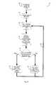
- FIG. 5is a flow chart for a process 80 that uses magnetic field measurements to determine a probe's gain, location, and orientation.
- Process 80provides an initial guess 82 for the probe's gain, location, and orientation.
- the initial guess of the probe's gain, location, and orientationmay include either a preselected fixed point or a randomly selected point in the (x, y, z, ⁇ , ⁇ ) space.
- process 80performs 84 iterative process 60 (of FIG. 4) to obtain a better guess for the probe's gain, location, and orientation. The better guess is based on the selected initial guess and the measured magnetic field values.
- Process 80may perform several iterative loops of process 60 to obtain a better guess, which is closer to an extremum of the optimization function used in process 60 .
- the optimization process 60provides a value for the optimization function (e.g., the ⁇ 2 function) and the loop count (which indicates the number of iterations performed to obtain the better guess).
- the value of the optimization functionprovides data indicative of the reliability of the better guess of the probe's gain, location, and orientation. Random measurement errors cause the value of the optimization function to fall on a probabilistic distribution function whose form is independent of the physical model for the magnetic field measurements. For the least-squares sum, the probabilistic distribution function is known as the ⁇ 2 -distribution. Systematic measurement errors also affect the value of the optimization function.
- the extrema of the optimization functioncan be maxima or minima and can fall into several classes.
- An extremummay be local or global extremum.
- Local and global extremaare distinguished by the associated values of the optimization function. For the least-squares sum, the value of the optimization function at a global minimum is smaller than the value of the function at a local minimum. Thus, global and local minima are associated with respective low and high values of the least-squares sum.
- An extremummay also correspond to a situation in which measurements of magnetic fields are either distorted or undistorted.
- values of the optimization function at global minima for undistorted measurementsare smaller than values of the optimization function at global minima for distorted measurements.
- values of the optimization function at global minima for distorted measurementsare smaller than values of the optimization function at local minima.
- values of the optimization function at extremacarry information about the quality of the estimates of a probe's gain, location, and orientation obtained through process 60 .
- the informationenables determining whether random or systematic errors are present.
- Values of the least-squares sum at extremaare typically ordered. The lowest values correspond to global minima in the absence of distortions to field measurements. Intermediate values correspond to global minima in the presence of distortions to field measurements. The highest values correspond to false or local minima for which estimates of the probe's gain, location, and position are not reliable.
- Distortionsmay occur during generation of magnetic fields, measurement of magnetic fields, acquisition of field measurements, or processing of field measurements.
- the distortions to the generation of magnetic fieldsmay occur due to a failure of a field source 16 1 ⁇ n , probe 42 , or field-generating module 22 or 51 .
- the distortion of magnetic field measurementsmay result from the presence of conductors or ferromagnetic materials in the monitored space, which distort the time-varying magnetic fields.
- Distortion during the acquisition or processing of magnetic field measurementsmay result from hardware or software failures (e.g., in electronics modules 26 , 52 or computers 28 , 54 ).
- a calibrationis performed to classify extrema of the optimization function.
- the calibrationclassifies extrema of the optimization function into three or more sets (S i ).
- One set (S G-ND )corresponds to real global extrema of the optimization function for which field measurements and field measurement processing is not distorted.
- Another set (S L )corresponds to false or local extrema of the optimization function.
- a third set (S G-D )corresponds to real global extrema of the optimization function for which either field measurements or field measurement processing is distorted.
- New setsmay be formed from the sets (S G-ND , S L , and S G-D ) by set intersection and union operations.
- One set (S ND )includes values of the optimization function that are only associated with extrema of the function for which field measurements and measurement processing are not distorted. This set (S ND ) is defined as S G-ND ⁇ (S L ⁇ S G-D ).
- Another set (S D )includes values of the optimization function that are only associated with global extrema of the function for which field measurements or field measurement processing is distorted. This set (S D ) is defined as S G-D ⁇ (S L ⁇ S G-ND ).
- Another set (S L0 )includes values of the optimization function that are only associated with false or local extrema of the function.
- This set (S L0 )is defined as S L ⁇ (S G-ND ⁇ S G-D ).
- a set (S ND-D )includes values of the optimization function that are only associated with global extrema of the function. For values in S ND-D , the field measurements and field measurement processing may or may not be distorted. S ND-D is defined as S G-ND ⁇ S G-D . In various embodiments, some of the above-described sets (S i ) may be empty.
- process 80uses the calibrated classification of values of the optimization function to classify extrema found with iterative process 60 .
- Process 80determines 86 whether the value of the optimization function at each extremum corresponds only to a global minimum without distortion (i.e., whether the value belongs to S G-ND ). If the value belongs to set S G-ND , process 80 registers 88 the associated “better” guess for the probe's gain, location, and orientation as the probe's gain, location, and orientation.
- process 80determines 87 if the system gain factor is within an acceptable range. If so, process 80 stops. If not, process 80 provides 93 a warning to the user that the system gain factor is out of range and, therefore, the probe's operating environment has changed.
- process 80determines 90 whether the value of the optimization function for the “better” guess corresponds to a global extremum in the presence of a distortion (i.e., whether the value belongs to S G-D ). If the value belongs to set S G-D , process 80 provides 92 a warning to the user and also registers 88 the new guess for the probe's gain, location, and orientation for the viewer to see.
- the warningmay be an audio signal or a flashing signal on a computer display for a user to hear or view.
- process 80also determines 94 whether the value of the optimization function corresponds to a local extremum (i.e., whether the value belongs to S L ). If the value belongs to S L , process 80 determines 96 whether the loop count (LC) is greater than a preselected timeout value (LC max ). If LC>LC max , process 80 generates 98 a timeout warning. If LC ⁇ LC max , process 80 loops back 99 to generate a better new guess for the probe's gain, location, and orientation (i.e., process 80 ignores the current new guess).
- LCloop count
- LC maxa preselected timeout value
- process 80selects a new initial guess for the probe's gain, location, and orientation (e.g., by randomly selecting a new gain (g) and a new point (x, y, z, ⁇ , ⁇ ) in the probe's coordinate space).
- Other processes for selecting the new initial guess so that the process 60 subsequently produces a better guess for a “global” extremumare known to persons of skill in the art.
- process 80tries to obtain a better guess for the gain, location, and position of the probe after producing a warning that a distortion is present. For example, if the number of field measurements is greater than the number of parameters plus one, process 80 may produce a better guess by discarding one of the measured field values B 1 ⁇ n measured and repeating process 80 . If the distortion affects only the discarded field value, discarding the distorted value will produce a better estimate of the probe's gain, location, and orientation.
- One field measurementmay be distorted because of the presence of a conductor near one field sensor or because of a hardware failure in one sensor.
- process 80handle overlapping extrema values, which belong to more than one of the sets of S L , S G-ND , and S G-D , differently.
- process 80may provide 92 a warning, indicate 88 the guessed probe location and orientation, and try to find a non-overlapping extrema value by repeating steps 82 and 84 for a new initial guess of the probe's gain, location, and orientation.
- the processmay generate a warning that identifies the extrema value as overlapping and then reselect an initial guess for the probe's gain, location, and orientation and re-execute process 60 to try to find a value not belonging to S L -S L0 .
- overlapping subsetssuch as S L -S L0 may also be empty.
- system gain factorcan also be used as a means for detecting measurement distortion.
- the basis for thisis the assumption that the system gain factor should remain essentially constant and stay within a defined range (which is typically determined during system calibration). Deviations from this range are indicative of a change in the probe's environment or in the system itself.
- This system gain factor range(SGFR) has to be chosen so that it can accommodate normal system gain factor variations for different probe positions and orientations throughout the operating volume. This range may also take into account gain variations caused by manufacturing tolerances and environmental factors (e.g., temperature variations, the presence of conductive objects, etc.).
- this automated uniform damping compensationallows for the determination of the probe's position/orientation within metallic tubes (e.g., a biopsy needle with a field sensor in its stylet). This allows for the tracking of the tip of a biopsy needle as it travels through the human body. This is an important advantage, as biopsy needles tend to bend and/or flex when passing through the body and, accordingly, the tip's position cannot be accurately interpolated. These advantages extend to other metallic tube objects, such as endoscopes, brachytherapy applicators etc.
- FIG. 6is a flow chart for a calibration process 100 that finds values of the optimization function at extrema to define the membership of sets S G-ND and S L . If iterative process 60 (of FIG. 4) generates a real global extremum, the probe's gain, location, and orientation found by process 60 correlate closely to the actual gain, location, and orientation of the probe. If iterative process 60 generates a false or local extremum of the optimization function, the probe's gain, location, and orientation found by process 60 do not correlate closely to the actual gain, location, and orientation of the probe.
- process 100positions 102 the probe at a selected location and orientation. Further, an initial gain is selected for the probe. The initial gain is based on an accepted range of gain values for a properly functioning probe.
- the probemounts on a mechanical positioning frame (not shown) that positions the probe at the selected location and orientation.
- the mechanical positioning frameis made of materials that do not distort magnetic fields and provides a separate measurement of the selected actual location and orientation of the probe. The separate measurements may be optical measurements or mechanical measurements.
- Process 100measures 104 the magnetic field values that correspond to the selected probe location and orientation.
- Process 100selects 106 an initial guess of the gain, location and position of the probe for optimization process 60 . From the measured field values and the initial guess, process 100 performs 108 iterative optimization procedure 60 to obtain a better-guess value of the probe's gain, location and orientation.
- the optimization procedure 60also provides a value for the optimization function that corresponds to the better guess for the probe gain, location and orientation and is a value of the optimization function at an extremum.
- Process 100compares 110 the better-guess and actual coordinates of the probe's gain, location and orientation to determine whether both coordinates are in close proximity to each other.
- the better guess (x N , y N , z N , ⁇ N , ⁇ N , g) and actual values (x, y, z, ⁇ , ⁇ , g) of the probe coordinatesare close if the values are within a preselected range of each other in a component-by-component fashion. If the better-guess and actual coordinates are close, the process 100 labels 112 the corresponding value of the optimization function as a value belonging to S G-ND . If the better-guess and actual probe coordinates are not close, process 100 labels 114 the corresponding value of the optimization function as a value belonging to S L .
- process 100loops back 116 and repeats steps 106 - 114 for other initial guesses of the probe's gain, location and orientation. These repetitions for different initial guesses cover the whole space (x, y, z, ⁇ , ⁇ , g) of possible probe coordinates representatively (e.g., by randomly selecting points in the (x, y, z, ⁇ , ⁇ , g) space).
- Process 100also repeats the classification of values of the optimization function at extrema for other selections of the actual probe gain, location and orientation.
- the repetitions for other actual probe gain, locations and orientationscover a representative portion of the parameter space (x, y, z, ⁇ , ⁇ , g) representatively (e.g., with randomly selected points).
- the representative portionmay be a portion of the entire space (x, y, z, ⁇ , ⁇ , g) that is related to other portions of the space by symmetry rotations.
- the optimization functionmay generate different extrema values of the optimization function that belong to S G-ND and/or S L .
- the optimization functionhas smaller values at global minima (i.e., in the presence or absence of measurement distortions) than at local minima.
- FIG. 7is a flow chart for a calibration process 120 that finds values of the optimization function belonging to S G-D .
- the values of S G-Dcorrespond to extrema of the optimization function that occur when distortions affect the iteration process 60 (of FIG. 4 ).
- Process 120may be performed separately for each type of distortion that can affect either magnetic field measurements or the processing of magnetic field measurements.
- the distortionsmay result from nearby conducting or ferrous objects, nearby field sources, sensor hardware failures, field source hardware/software failures, and/or software measurement processing failures.
- Process 120physically sets up 122 a selected type of distortion for the system.
- the setting up of a distortionmay include placing a pair of conducting scissors inside the monitored volume or causing a hardware failure in the electronics module.
- process 120positions 124 the probe with the mechanical positioning frame and receives the value of the probe's actual location and orientation. Further, an initial gain is selected for the probe. The initial gain is based on an accepted range of gain values for a properly functioning probe.
- the processalso measures 126 the magnetic field values that depend on the probe's actual gain, location and orientation. Process 120 also selects 128 an initial guess for the gain, location and orientation of the probe.
- process 120utilizes 130 the iterative process 60 to obtain a better guess for the probe's gain, location and orientation. Iterative process 60 returns an associated extrema value of the optimization function that corresponds to each better guess. Process 120 determines 132 whether the new value is better than other extrema values of the optimization function, which were generated from different initial guesses for the probe's gain, location and position. For the least-squares sum, the best extrema value is the minimum value.
- the process 120labels 134 the new value as a value of the optimization function at a global extremum (i.e., as a member of S G-D ). Values of the optimization function that belong to S G-D indicate the presence of distortion. If the new value is not better than earlier values of the optimization function associated with accepted guesses, process 120 labels 136 the new value as a value that corresponds to a false or local extremum. After classifying the extrema value, process 120 loops back 138 , 140 to repeat the search for values of the optimization function at other extrema by selecting a different initial guess for the probe's gain, location and orientation. The best extrema value for various initial guesses of the probe's gain, location and orientation provides a value in S G-D .
- the processalso repeats the search for values of the optimization function in S G-D for different actual gains, locations and orientations of the probe. For each actual gain, orientation and location, an extrema value of the optimization function in S G-D may be generated. Similarly, different positions of a distorting object (e.g., objects 30 and 32 of FIG. 1) may generate different extrema values of the optimization function, which belong to S G-D .
- a distorting objecte.g., objects 30 and 32 of FIG. 1
- the extrema values of the optimization function for different types of distortionare distinguishable. Distinguishable extrema values fall in different ranges.
- calibration process 120is performed separately for the different types of distortion to obtain ranges of extrema values of the optimization function for each separate type of distortion.
- Process 80uses the extrema values to classify the type of distortion, e.g., hardware failure, software failure, or nearby conducting object.
- FIG. 8shows a computer 142 that determines the gain, location, and orientation of a probe from measurements of magnetic fields and indicates the presence of distortions to the determinations.
- Computer 142may be an embodiment for computer 28 of FIG. 1 or computer 54 of FIG. 3 .
- Computer 142receives data on measured magnetic field values from a line 144 that connects to an output of an electronics module 146 .
- the module 146may be module 26 (FIG. 1) or module 52 (FIG. 3 ).
- Computer 142processes the data according to processes 60 (FIG. 4) and 80 (FIG. 5) to determine a probe's gain, location, and orientation and the presence or absence of distortion.
- Computer 142displays the results of the determinations on a screen 148 .
- Computer 142has a data storage drive 154 (e.g., a hard disk or optical drive) for storing the above-described executable programs/processes and the data generated therefrom.
- a data storage drive 154e.g., a hard disk or optical drive
Landscapes
- Engineering & Computer Science (AREA)
- Life Sciences & Earth Sciences (AREA)
- Health & Medical Sciences (AREA)
- Remote Sensing (AREA)
- Physics & Mathematics (AREA)
- Biomedical Technology (AREA)
- Surgery (AREA)
- General Life Sciences & Earth Sciences (AREA)
- General Physics & Mathematics (AREA)
- Geophysics (AREA)
- Human Computer Interaction (AREA)
- Environmental & Geological Engineering (AREA)
- Biophysics (AREA)
- Pathology (AREA)
- Electromagnetism (AREA)
- Heart & Thoracic Surgery (AREA)
- Medical Informatics (AREA)
- Molecular Biology (AREA)
- Geology (AREA)
- Animal Behavior & Ethology (AREA)
- General Health & Medical Sciences (AREA)
- Public Health (AREA)
- Veterinary Medicine (AREA)
- Measurement Of Length, Angles, Or The Like Using Electric Or Magnetic Means (AREA)
- Measuring Magnetic Variables (AREA)
- Navigation (AREA)
- Measurement Of The Respiration, Hearing Ability, Form, And Blood Characteristics Of Living Organisms (AREA)
- Vessels, Lead-In Wires, Accessory Apparatuses For Cathode-Ray Tubes (AREA)
- Vehicle Body Suspensions (AREA)
- Body Structure For Vehicles (AREA)
Abstract
Description
Claims (42)
Priority Applications (11)
| Application Number | Priority Date | Filing Date | Title |
|---|---|---|---|
| US09/892,153US6625563B2 (en) | 2001-06-26 | 2001-06-26 | Gain factor and position determination system |
| CN2007101802334ACN101149440B (en) | 2001-06-26 | 2002-06-25 | A gain factor and position determination system |
| EP02740177AEP1399765B1 (en) | 2001-06-26 | 2002-06-25 | A gain factor and position determination system |
| AT02740177TATE370430T1 (en) | 2001-06-26 | 2002-06-25 | DEVICE FOR DETERMINING POSITION AND GAIN FACTOR |
| JP2003507586AJP2004536298A (en) | 2001-06-26 | 2002-06-25 | Gain factor and position determination system |
| CA2451862ACA2451862C (en) | 2001-06-26 | 2002-06-25 | A gain factor and position determination system |
| DE60221833TDE60221833T2 (en) | 2001-06-26 | 2002-06-25 | DEVICE FOR DETERMINING THE POSITION AND THE REINFORCING FACTOR |
| CNB028162552ACN100351651C (en) | 2001-06-26 | 2002-06-25 | Gain factor and position determination system |
| EP07111645AEP1865342A3 (en) | 2001-06-26 | 2002-06-25 | A gain factor and position determination system |
| PCT/CH2002/000345WO2003001244A1 (en) | 2001-06-26 | 2002-06-25 | A gain factor and position determination system |
| US10/624,917US6990427B2 (en) | 2001-06-26 | 2003-07-22 | Gain factor and position determination system |
Applications Claiming Priority (1)
| Application Number | Priority Date | Filing Date | Title |
|---|---|---|---|
| US09/892,153US6625563B2 (en) | 2001-06-26 | 2001-06-26 | Gain factor and position determination system |
Related Child Applications (1)
| Application Number | Title | Priority Date | Filing Date |
|---|---|---|---|
| US10/624,917ContinuationUS6990427B2 (en) | 2001-06-26 | 2003-07-22 | Gain factor and position determination system |
Publications (2)
| Publication Number | Publication Date |
|---|---|
| US20020198676A1 US20020198676A1 (en) | 2002-12-26 |
| US6625563B2true US6625563B2 (en) | 2003-09-23 |
Family
ID=25399464
Family Applications (2)
| Application Number | Title | Priority Date | Filing Date |
|---|---|---|---|
| US09/892,153Expired - LifetimeUS6625563B2 (en) | 2001-06-26 | 2001-06-26 | Gain factor and position determination system |
| US10/624,917Expired - LifetimeUS6990427B2 (en) | 2001-06-26 | 2003-07-22 | Gain factor and position determination system |
Family Applications After (1)
| Application Number | Title | Priority Date | Filing Date |
|---|---|---|---|
| US10/624,917Expired - LifetimeUS6990427B2 (en) | 2001-06-26 | 2003-07-22 | Gain factor and position determination system |
Country Status (8)
| Country | Link |
|---|---|
| US (2) | US6625563B2 (en) |
| EP (2) | EP1865342A3 (en) |
| JP (1) | JP2004536298A (en) |
| CN (2) | CN101149440B (en) |
| AT (1) | ATE370430T1 (en) |
| CA (1) | CA2451862C (en) |
| DE (1) | DE60221833T2 (en) |
| WO (1) | WO2003001244A1 (en) |
Cited By (38)
| Publication number | Priority date | Publication date | Assignee | Title |
|---|---|---|---|---|
| US20050049820A1 (en)* | 2001-06-26 | 2005-03-03 | Northern Digital, Canada Corporation | Gain factor and position determination system |
| US20050107654A1 (en)* | 2003-11-17 | 2005-05-19 | Riehl Mark E. | Determining stimulation levels for transcranial magnetic stimulation |
| US20050148808A1 (en)* | 2004-01-06 | 2005-07-07 | Allan Cameron | Method and apparatus for coil positioning for TMS studies |
| US20050234286A1 (en)* | 2004-04-15 | 2005-10-20 | Riehl Mark E | Method and apparatus for determining the proximity of a TMS coil to a subject's head |
| US20060161039A1 (en)* | 2005-01-20 | 2006-07-20 | Neuronetics, Inc. | Articulating arm |
| US20060199159A1 (en)* | 2005-03-01 | 2006-09-07 | Neuronetics, Inc. | Head phantom for simulating the patient response to magnetic stimulation |
| US20070078678A1 (en)* | 2005-09-30 | 2007-04-05 | Disilvestro Mark R | System and method for performing a computer assisted orthopaedic surgical procedure |
| US20080052034A1 (en)* | 2002-04-05 | 2008-02-28 | Commissariat A L'energie Atomique | System and method for rotational motion capture of a solid |
| US7471202B2 (en) | 2006-03-29 | 2008-12-30 | General Electric Co. | Conformal coil array for a medical tracking system |
| US7525309B2 (en) | 2005-12-30 | 2009-04-28 | Depuy Products, Inc. | Magnetic sensor array |
| US7532997B2 (en) | 2006-04-17 | 2009-05-12 | General Electric Company | Electromagnetic tracking using a discretized numerical field model |
| US20090227830A1 (en)* | 2008-03-10 | 2009-09-10 | Neuronetics, Inc. | Apparatus for coil positioning for tms studies |
| WO2010105551A1 (en) | 2009-03-16 | 2010-09-23 | 微创医疗器械(上海)有限公司 | Human cavity wall three-dimensional measure method, instrument and system |
| US20110015464A1 (en)* | 2005-07-27 | 2011-01-20 | Neuronetics, Inc. | Magnetic core for medical procedures |
| DE102011013398A1 (en) | 2010-03-10 | 2011-09-15 | Northern Digital Inc. | Magnetic location system |
| US8068648B2 (en) | 2006-12-21 | 2011-11-29 | Depuy Products, Inc. | Method and system for registering a bone of a patient with a computer assisted orthopaedic surgery system |
| US8265949B2 (en) | 2007-09-27 | 2012-09-11 | Depuy Products, Inc. | Customized patient surgical plan |
| US8343159B2 (en) | 2007-09-30 | 2013-01-01 | Depuy Products, Inc. | Orthopaedic bone saw and method of use thereof |
| US8391952B2 (en) | 2007-10-11 | 2013-03-05 | General Electric Company | Coil arrangement for an electromagnetic tracking system |
| US8641210B2 (en) | 2011-11-30 | 2014-02-04 | Izi Medical Products | Retro-reflective marker including colored mounting portion |
| US8661573B2 (en) | 2012-02-29 | 2014-03-04 | Izi Medical Products | Protective cover for medical device having adhesive mechanism |
| US8862200B2 (en) | 2005-12-30 | 2014-10-14 | DePuy Synthes Products, LLC | Method for determining a position of a magnetic source |
| US10188831B2 (en) | 2013-03-14 | 2019-01-29 | Angiodynamics, Inc. | Systems and methods for catheter tip placement using ECG |
| US10235904B2 (en) | 2014-12-01 | 2019-03-19 | Truinject Corp. | Injection training tool emitting omnidirectional light |
| US10269266B2 (en) | 2017-01-23 | 2019-04-23 | Truinject Corp. | Syringe dose and position measuring apparatus |
| US10290231B2 (en) | 2014-03-13 | 2019-05-14 | Truinject Corp. | Automated detection of performance characteristics in an injection training system |
| US10500340B2 (en) | 2015-10-20 | 2019-12-10 | Truinject Corp. | Injection system |
| US10643497B2 (en) | 2012-10-30 | 2020-05-05 | Truinject Corp. | System for cosmetic and therapeutic training |
| US10743942B2 (en) | 2016-02-29 | 2020-08-18 | Truinject Corp. | Cosmetic and therapeutic injection safety systems, methods, and devices |
| US10849688B2 (en) | 2016-03-02 | 2020-12-01 | Truinject Corp. | Sensory enhanced environments for injection aid and social training |
| US10896627B2 (en) | 2014-01-17 | 2021-01-19 | Truinjet Corp. | Injection site training system |
| EP3785612A1 (en) | 2019-08-27 | 2021-03-03 | Biosense Webster (Israel) Ltd | Accurate basket catheter tracking |
| US11051829B2 (en) | 2018-06-26 | 2021-07-06 | DePuy Synthes Products, Inc. | Customized patient-specific orthopaedic surgical instrument |
| US11055648B2 (en) | 2006-05-25 | 2021-07-06 | DePuy Synthes Products, Inc. | Method and system for managing inventories of orthopaedic implants |
| US11607150B2 (en) | 2014-04-08 | 2023-03-21 | Angiodynamics Va Llc | Medical device placement system and a method for its use |
| DE102023106487A1 (en) | 2022-03-18 | 2023-09-21 | Northern Digital Inc. | FIELD GENERATOR ALIGNMENT FOR MAGNETIC TRACKING IN PLANAR FIELD GENERATING ASSEMBLY |
| US12217626B2 (en) | 2012-10-30 | 2025-02-04 | Truinject Corp. | Injection training apparatus using 3D position sensor |
| US12369981B2 (en) | 2023-02-07 | 2025-07-29 | Depuy Ireland Unlimited Company | Systems and methods for bone model registration with adaptive soft tissue thickness |
Families Citing this family (50)
| Publication number | Priority date | Publication date | Assignee | Title |
|---|---|---|---|---|
| US7158754B2 (en)* | 2003-07-01 | 2007-01-02 | Ge Medical Systems Global Technology Company, Llc | Electromagnetic tracking system and method using a single-coil transmitter |
| JP4547181B2 (en)* | 2004-04-01 | 2010-09-22 | オリンパス株式会社 | In-subject position detection system |
| JP5030392B2 (en)* | 2004-06-14 | 2012-09-19 | オリンパス株式会社 | Medical device position detection system and medical device guidance system |
| KR100615881B1 (en)* | 2004-06-21 | 2006-08-25 | 한국과학기술연구원 | Capsule Endoscope Control System |
| CN101080198B (en)* | 2004-12-17 | 2010-12-08 | 奥林巴斯株式会社 | Position detection system, guidance system, position detection method, medical device, and medical magnetic induction and position detection system |
| JP4679200B2 (en)* | 2005-03-28 | 2011-04-27 | オリンパス株式会社 | Capsule type medical device position detection system, capsule type medical device guidance system, and capsule type medical device position detection method |
| JP5117051B2 (en)* | 2004-12-20 | 2013-01-09 | 株式会社日立メディコ | Ultrasonic diagnostic system and method |
| JP2006212051A (en)* | 2005-02-01 | 2006-08-17 | Yamaha Corp | Capsule type imaging device, in vivo imaging system and in vivo imaging method |
| DE102005032577B4 (en)* | 2005-07-11 | 2012-09-20 | Siemens Ag | Method for determining the position of an endo robot |
| US8000772B2 (en)* | 2005-10-19 | 2011-08-16 | Biosense Webster, Inc. | Metal immunity in a reverse magnetic system |
| US7727240B1 (en) | 2006-02-15 | 2010-06-01 | Blake Benton | Method and system for securing an intramedullary nail |
| US9364293B2 (en)* | 2006-04-28 | 2016-06-14 | Biosense Webster, Inc. | Reduced field distortion in medical tools |
| WO2007132449A2 (en)* | 2006-05-11 | 2007-11-22 | Yossi Gross | Implantable respiration therapy device |
| JP5441689B2 (en) | 2006-05-13 | 2014-03-12 | テンシス メディカル インコーポレイテッド | Continuous positioning apparatus and method |
| US7985254B2 (en) | 2007-01-08 | 2011-07-26 | David Tolkowsky | Endobronchial fluid exhaler devices and methods for use thereof |
| US8821376B2 (en)* | 2007-03-12 | 2014-09-02 | David Tolkowsky | Devices and methods for performing medical procedures in tree-like luminal structures |
| US8239003B2 (en)* | 2007-04-16 | 2012-08-07 | General Electric Company | System and method of integrating electromagnetic microsensors in guidewires |
| JP5004646B2 (en)* | 2007-04-26 | 2012-08-22 | 旭化成エレクトロニクス株式会社 | Position / orientation detection system, detection method thereof, and position / orientation detection apparatus |
| JP4931145B2 (en)* | 2007-08-15 | 2012-05-16 | 日本電信電話株式会社 | Magnetic three-dimensional position detection apparatus, magnetic three-dimensional position detection method, program, and recording medium |
| EP2028504B1 (en)* | 2007-08-23 | 2016-04-13 | STMicroelectronics Srl | Method and device for calibrating a magnetic sensor |
| CN101896117B (en) | 2007-10-12 | 2015-03-04 | 坦西斯医药股份有限公司 | Device and method for non-invasive measurement of arterial blood pressure in a patient |
| US9002435B2 (en)* | 2008-06-30 | 2015-04-07 | General Electric Company | System and method for integrating electromagnetic microsensors in guidewires |
| JP2011024606A (en)* | 2009-07-21 | 2011-02-10 | Machida Endscope Co Ltd | Endoscope and endoscope system |
| JP5317874B2 (en)* | 2009-07-21 | 2013-10-16 | 株式会社町田製作所 | Endoscope and endoscope system |
| JP5686739B2 (en)* | 2009-10-27 | 2015-03-18 | 株式会社日立メディコ | Inspection device with magnetic position detector, magnetic field measurement tool, magnetic field detection program |
| US8686721B2 (en) | 2012-02-27 | 2014-04-01 | The Johns Hopkins University | Automated pre-processing of body-mounted magnetometer data from constellations of low earth orbit satellites for derivation of birkeland current signatures |
| DE102012013534B3 (en) | 2012-07-05 | 2013-09-19 | Tobias Sokolowski | Apparatus for repetitive nerve stimulation for the degradation of adipose tissue by means of inductive magnetic fields |
| US8818486B2 (en)* | 2012-07-12 | 2014-08-26 | Biosense Webster (Israel) Ltd. | Position and orientation algorithm for a single axis sensor |
| MX2016007236A (en)* | 2013-12-04 | 2016-08-04 | Obalon Therapeutics Inc | Systems and methods for locating and/or characterizing intragastric devices. |
| US10393910B2 (en)* | 2015-02-11 | 2019-08-27 | Cgg Services Sas | Apparatus for airborne geophysical prospecting using both natural and controlled source fields and method |
| US11491342B2 (en) | 2015-07-01 | 2022-11-08 | Btl Medical Solutions A.S. | Magnetic stimulation methods and devices for therapeutic treatments |
| US20180001107A1 (en) | 2016-07-01 | 2018-01-04 | Btl Holdings Limited | Aesthetic method of biological structure treatment by magnetic field |
| US10695575B1 (en) | 2016-05-10 | 2020-06-30 | Btl Medical Technologies S.R.O. | Aesthetic method of biological structure treatment by magnetic field |
| JP6501726B2 (en) | 2016-04-19 | 2019-04-17 | 三菱電機株式会社 | Probe position inspection apparatus, semiconductor evaluation apparatus and probe position inspection method |
| US11247039B2 (en) | 2016-05-03 | 2022-02-15 | Btl Healthcare Technologies A.S. | Device including RF source of energy and vacuum system |
| US11464993B2 (en) | 2016-05-03 | 2022-10-11 | Btl Healthcare Technologies A.S. | Device including RF source of energy and vacuum system |
| US11534619B2 (en) | 2016-05-10 | 2022-12-27 | Btl Medical Solutions A.S. | Aesthetic method of biological structure treatment by magnetic field |
| US10583287B2 (en) | 2016-05-23 | 2020-03-10 | Btl Medical Technologies S.R.O. | Systems and methods for tissue treatment |
| US10556122B1 (en) | 2016-07-01 | 2020-02-11 | Btl Medical Technologies S.R.O. | Aesthetic method of biological structure treatment by magnetic field |
| US11141219B1 (en) | 2016-08-16 | 2021-10-12 | BTL Healthcare Technologies, a.s. | Self-operating belt |
| US10267872B2 (en) | 2017-09-14 | 2019-04-23 | Siemens Energy, Inc. | Magnetic flux probe data streamer for a generator |
| WO2020092297A1 (en)* | 2018-10-30 | 2020-05-07 | Boston Scientific Scimed, Inc. | Devices and methods for treatment of body lumens |
| ES2926904T3 (en) | 2019-04-11 | 2022-10-31 | Btl Medical Solutions A S | Device for the aesthetic treatment of biological structures using radiofrequency and magnetic energy |
| US12156689B2 (en) | 2019-04-11 | 2024-12-03 | Btl Medical Solutions A.S. | Methods and devices for aesthetic treatment of biological structures by radiofrequency and magnetic energy |
| US11878167B2 (en) | 2020-05-04 | 2024-01-23 | Btl Healthcare Technologies A.S. | Device and method for unattended treatment of a patient |
| WO2021224678A1 (en) | 2020-05-04 | 2021-11-11 | Btl Medical Technologies S.R.O. | Device and method for unattended treatment of a patient |
| DE102020207428A1 (en) | 2020-06-16 | 2021-12-16 | Robert Bosch Gesellschaft mit beschränkter Haftung | Method for calibrating a sensor model for determining a pose with a neural network as a pose determination model |
| EP4415812A1 (en) | 2021-10-13 | 2024-08-21 | BTL Medical Solutions a.s. | Devices for aesthetic treatment of biological structures by radiofrequency and magnetic energy |
| US11896816B2 (en) | 2021-11-03 | 2024-02-13 | Btl Healthcare Technologies A.S. | Device and method for unattended treatment of a patient |
| WO2023128974A1 (en)* | 2021-12-31 | 2023-07-06 | Erciyes Universitesi Strateji Gelistirme Daire Baskanligi | A system and method for detecting the position of a robotic capsule endoscope with permanent magnet inside the body |
Citations (14)
| Publication number | Priority date | Publication date | Assignee | Title |
|---|---|---|---|---|
| US5392210A (en) | 1991-08-16 | 1995-02-21 | Siemens Aktiengesellschaft | Method for locating the position of electrophysiological activities |
| US5457641A (en) | 1990-06-29 | 1995-10-10 | Sextant Avionique | Method and apparatus for determining an orientation associated with a mobile system, especially a line of sight inside a helmet visor |
| US5592939A (en) | 1995-06-14 | 1997-01-14 | Martinelli; Michael A. | Method and system for navigating a catheter probe |
| WO1997036192A1 (en) | 1996-03-27 | 1997-10-02 | Paul Scherrer Institut | Device and process for determining position |
| US5747996A (en) | 1994-03-09 | 1998-05-05 | U.S. Philips Corporation | Device for determining the spatial position of a sensor element which is displacement relative to a reference element |
| US5762064A (en) | 1995-01-23 | 1998-06-09 | Northrop Grumman Corporation | Medical magnetic positioning system and method for determining the position of a magnetic probe |
| US5767669A (en) | 1996-06-14 | 1998-06-16 | Ascension Technology Corporation | Magnetic field position and orientation measurement system with dynamic eddy current rejection |
| US5879297A (en)* | 1997-05-08 | 1999-03-09 | Lucent Medical Systems, Inc. | System and method to determine the location and orientation of an indwelling medical device |
| GB2331807A (en) | 1997-11-15 | 1999-06-02 | Roke Manor Research | Catheter tracking system |
| US5913820A (en) | 1992-08-14 | 1999-06-22 | British Telecommunications Public Limited Company | Position location system |
| US6073043A (en)* | 1997-12-22 | 2000-06-06 | Cormedica Corporation | Measuring position and orientation using magnetic fields |
| US6097190A (en) | 1996-11-26 | 2000-08-01 | Institut Dr. Friedrich Foerster Pruefgeraetebau Gmbh & Co. Kg | Method and device for locating and identifying search objects concealed in the ground, particularly plastic mines |
| US6266551B1 (en)* | 1996-02-15 | 2001-07-24 | Biosense, Inc. | Catheter calibration and usage monitoring system |
| US6427079B1 (en)* | 1999-08-09 | 2002-07-30 | Cormedica Corporation | Position and orientation measuring with magnetic fields |
Family Cites Families (6)
| Publication number | Priority date | Publication date | Assignee | Title |
|---|---|---|---|---|
| US5645065A (en)* | 1991-09-04 | 1997-07-08 | Navion Biomedical Corporation | Catheter depth, position and orientation location system |
| US5558091A (en)* | 1993-10-06 | 1996-09-24 | Biosense, Inc. | Magnetic determination of position and orientation |
| US6690963B2 (en) | 1995-01-24 | 2004-02-10 | Biosense, Inc. | System for determining the location and orientation of an invasive medical instrument |
| CN1091521C (en)* | 1995-08-01 | 2002-09-25 | 株式会社立普罗 | Location marking system and marker for use in system |
| US6052610A (en)* | 1998-01-09 | 2000-04-18 | International Business Machines Corporation | Magnetic catheter tracker and method therefor |
| US6625563B2 (en)* | 2001-06-26 | 2003-09-23 | Northern Digital Inc. | Gain factor and position determination system |
- 2001
- 2001-06-26USUS09/892,153patent/US6625563B2/ennot_activeExpired - Lifetime
- 2002
- 2002-06-25CNCN2007101802334Apatent/CN101149440B/ennot_activeExpired - Lifetime
- 2002-06-25ATAT02740177Tpatent/ATE370430T1/ennot_activeIP Right Cessation
- 2002-06-25WOPCT/CH2002/000345patent/WO2003001244A1/enactiveIP Right Grant
- 2002-06-25CACA2451862Apatent/CA2451862C/ennot_activeExpired - Lifetime
- 2002-06-25CNCNB028162552Apatent/CN100351651C/ennot_activeExpired - Lifetime
- 2002-06-25EPEP07111645Apatent/EP1865342A3/ennot_activeWithdrawn
- 2002-06-25EPEP02740177Apatent/EP1399765B1/ennot_activeExpired - Lifetime
- 2002-06-25DEDE60221833Tpatent/DE60221833T2/ennot_activeExpired - Lifetime
- 2002-06-25JPJP2003507586Apatent/JP2004536298A/enactivePending
- 2003
- 2003-07-22USUS10/624,917patent/US6990427B2/ennot_activeExpired - Lifetime
Patent Citations (14)
| Publication number | Priority date | Publication date | Assignee | Title |
|---|---|---|---|---|
| US5457641A (en) | 1990-06-29 | 1995-10-10 | Sextant Avionique | Method and apparatus for determining an orientation associated with a mobile system, especially a line of sight inside a helmet visor |
| US5392210A (en) | 1991-08-16 | 1995-02-21 | Siemens Aktiengesellschaft | Method for locating the position of electrophysiological activities |
| US5913820A (en) | 1992-08-14 | 1999-06-22 | British Telecommunications Public Limited Company | Position location system |
| US5747996A (en) | 1994-03-09 | 1998-05-05 | U.S. Philips Corporation | Device for determining the spatial position of a sensor element which is displacement relative to a reference element |
| US5762064A (en) | 1995-01-23 | 1998-06-09 | Northrop Grumman Corporation | Medical magnetic positioning system and method for determining the position of a magnetic probe |
| US5592939A (en) | 1995-06-14 | 1997-01-14 | Martinelli; Michael A. | Method and system for navigating a catheter probe |
| US6266551B1 (en)* | 1996-02-15 | 2001-07-24 | Biosense, Inc. | Catheter calibration and usage monitoring system |
| WO1997036192A1 (en) | 1996-03-27 | 1997-10-02 | Paul Scherrer Institut | Device and process for determining position |
| US5767669A (en) | 1996-06-14 | 1998-06-16 | Ascension Technology Corporation | Magnetic field position and orientation measurement system with dynamic eddy current rejection |
| US6097190A (en) | 1996-11-26 | 2000-08-01 | Institut Dr. Friedrich Foerster Pruefgeraetebau Gmbh & Co. Kg | Method and device for locating and identifying search objects concealed in the ground, particularly plastic mines |
| US5879297A (en)* | 1997-05-08 | 1999-03-09 | Lucent Medical Systems, Inc. | System and method to determine the location and orientation of an indwelling medical device |
| GB2331807A (en) | 1997-11-15 | 1999-06-02 | Roke Manor Research | Catheter tracking system |
| US6073043A (en)* | 1997-12-22 | 2000-06-06 | Cormedica Corporation | Measuring position and orientation using magnetic fields |
| US6427079B1 (en)* | 1999-08-09 | 2002-07-30 | Cormedica Corporation | Position and orientation measuring with magnetic fields |
Non-Patent Citations (2)
| Title |
|---|
| Borse, G. J., "Numerical Methods with Matlab: A Resource for Scientists and Engineers," 1997, PWS Publishing Company, pp. 313-316.* |
| U.S. patent application Publication (US 2002/0065455 A1)-Ben-Haim et al.** |
Cited By (83)
| Publication number | Priority date | Publication date | Assignee | Title |
|---|---|---|---|---|
| US6990427B2 (en)* | 2001-06-26 | 2006-01-24 | Northern Digital Inc. | Gain factor and position determination system |
| US20050049820A1 (en)* | 2001-06-26 | 2005-03-03 | Northern Digital, Canada Corporation | Gain factor and position determination system |
| US20080052034A1 (en)* | 2002-04-05 | 2008-02-28 | Commissariat A L'energie Atomique | System and method for rotational motion capture of a solid |
| US20050107654A1 (en)* | 2003-11-17 | 2005-05-19 | Riehl Mark E. | Determining stimulation levels for transcranial magnetic stimulation |
| US7104947B2 (en) | 2003-11-17 | 2006-09-12 | Neuronetics, Inc. | Determining stimulation levels for transcranial magnetic stimulation |
| US20050148808A1 (en)* | 2004-01-06 | 2005-07-07 | Allan Cameron | Method and apparatus for coil positioning for TMS studies |
| US7651459B2 (en) | 2004-01-06 | 2010-01-26 | Neuronetics, Inc. | Method and apparatus for coil positioning for TMS studies |
| US9681841B2 (en) | 2004-04-15 | 2017-06-20 | Neuronetics, Inc. | Method and apparatus for determining the proximity of a TMS coil to a subject's head |
| US20050234286A1 (en)* | 2004-04-15 | 2005-10-20 | Riehl Mark E | Method and apparatus for determining the proximity of a TMS coil to a subject's head |
| US8177702B2 (en) | 2004-04-15 | 2012-05-15 | Neuronetics, Inc. | Method and apparatus for determining the proximity of a TMS coil to a subject's head |
| US9421392B2 (en) | 2004-04-15 | 2016-08-23 | Neuronetics, Inc. | Method and apparatus for determining the proximity of a TMS coil to a subject's head |
| US10596385B2 (en) | 2004-04-15 | 2020-03-24 | Neuronetics, Inc. | Method and apparatus for determining the proximity of a TMS coil to a subject's head |
| US20060161039A1 (en)* | 2005-01-20 | 2006-07-20 | Neuronetics, Inc. | Articulating arm |
| US8088058B2 (en) | 2005-01-20 | 2012-01-03 | Neuronetics, Inc. | Articulating arm |
| US20060199159A1 (en)* | 2005-03-01 | 2006-09-07 | Neuronetics, Inc. | Head phantom for simulating the patient response to magnetic stimulation |
| US9931518B2 (en) | 2005-07-27 | 2018-04-03 | Neuronetics, Inc. | Magnetic core for medical procedures |
| US10617884B2 (en) | 2005-07-27 | 2020-04-14 | Neurontics, Inc. | Magnetic core for medical procedures |
| US20110015464A1 (en)* | 2005-07-27 | 2011-01-20 | Neuronetics, Inc. | Magnetic core for medical procedures |
| US9308386B2 (en) | 2005-07-27 | 2016-04-12 | Neuronetics, Inc. | Magnetic core for medical procedures |
| US8657731B2 (en) | 2005-07-27 | 2014-02-25 | Neuronetics, Inc. | Magnetic core for medical procedures |
| US8246529B2 (en) | 2005-07-27 | 2012-08-21 | Neuronetics, Inc. | Magnetic core for medical procedures |
| US20070078678A1 (en)* | 2005-09-30 | 2007-04-05 | Disilvestro Mark R | System and method for performing a computer assisted orthopaedic surgical procedure |
| US8862200B2 (en) | 2005-12-30 | 2014-10-14 | DePuy Synthes Products, LLC | Method for determining a position of a magnetic source |
| US8148978B2 (en) | 2005-12-30 | 2012-04-03 | Depuy Products, Inc. | Magnetic sensor array |
| US7525309B2 (en) | 2005-12-30 | 2009-04-28 | Depuy Products, Inc. | Magnetic sensor array |
| US7471202B2 (en) | 2006-03-29 | 2008-12-30 | General Electric Co. | Conformal coil array for a medical tracking system |
| US7532997B2 (en) | 2006-04-17 | 2009-05-12 | General Electric Company | Electromagnetic tracking using a discretized numerical field model |
| US11055648B2 (en) | 2006-05-25 | 2021-07-06 | DePuy Synthes Products, Inc. | Method and system for managing inventories of orthopaedic implants |
| US11928625B2 (en) | 2006-05-25 | 2024-03-12 | DePuy Synthes Products, Inc. | System and method for performing a computer assisted orthopaedic surgical procedure |
| US11068822B2 (en) | 2006-05-25 | 2021-07-20 | DePuy Synthes Products, Inc. | System and method for performing a computer assisted orthopaedic surgical procedure |
| US8068648B2 (en) | 2006-12-21 | 2011-11-29 | Depuy Products, Inc. | Method and system for registering a bone of a patient with a computer assisted orthopaedic surgery system |
| US8265949B2 (en) | 2007-09-27 | 2012-09-11 | Depuy Products, Inc. | Customized patient surgical plan |
| US12070231B2 (en) | 2007-09-27 | 2024-08-27 | DePuy Synthes Products, Inc. | Customized patient surgical plan |
| US10828046B2 (en) | 2007-09-30 | 2020-11-10 | DePuy Synthes Products, Inc. | Apparatus and method for fabricating a customized patient-specific orthopaedic instrument |
| US11696768B2 (en) | 2007-09-30 | 2023-07-11 | DePuy Synthes Products, Inc. | Apparatus and method for fabricating a customized patient-specific orthopaedic instrument |
| US8361076B2 (en) | 2007-09-30 | 2013-01-29 | Depuy Products, Inc. | Patient-customizable device and system for performing an orthopaedic surgical procedure |
| US11931049B2 (en) | 2007-09-30 | 2024-03-19 | DePuy Synthes Products, Inc. | Apparatus and method for fabricating a customized patient-specific orthopaedic instrument |
| US10028750B2 (en) | 2007-09-30 | 2018-07-24 | DePuy Synthes Products, Inc. | Apparatus and method for fabricating a customized patient-specific orthopaedic instrument |
| US8357166B2 (en) | 2007-09-30 | 2013-01-22 | Depuy Products, Inc. | Customized patient-specific instrumentation and method for performing a bone re-cut |
| US8343159B2 (en) | 2007-09-30 | 2013-01-01 | Depuy Products, Inc. | Orthopaedic bone saw and method of use thereof |
| US8391952B2 (en) | 2007-10-11 | 2013-03-05 | General Electric Company | Coil arrangement for an electromagnetic tracking system |
| US20090227830A1 (en)* | 2008-03-10 | 2009-09-10 | Neuronetics, Inc. | Apparatus for coil positioning for tms studies |
| US9884200B2 (en) | 2008-03-10 | 2018-02-06 | Neuronetics, Inc. | Apparatus for coil positioning for TMS studies |
| WO2010105551A1 (en) | 2009-03-16 | 2010-09-23 | 微创医疗器械(上海)有限公司 | Human cavity wall three-dimensional measure method, instrument and system |
| DE102011013398A1 (en) | 2010-03-10 | 2011-09-15 | Northern Digital Inc. | Magnetic location system |
| US8668344B2 (en) | 2011-11-30 | 2014-03-11 | Izi Medical Products | Marker sphere including edged opening to aid in molding |
| US8651274B2 (en) | 2011-11-30 | 2014-02-18 | Izi Medical Products | Packaging for retro-reflective markers |
| US8672490B2 (en) | 2011-11-30 | 2014-03-18 | Izi Medical Products | High reflectivity retro-reflective marker |
| US8641210B2 (en) | 2011-11-30 | 2014-02-04 | Izi Medical Products | Retro-reflective marker including colored mounting portion |
| US8646921B2 (en) | 2011-11-30 | 2014-02-11 | Izi Medical Products | Reflective marker being radio-opaque for MRI |
| US8668342B2 (en) | 2011-11-30 | 2014-03-11 | Izi Medical Products | Material thickness control over retro-reflective marker |
| US8668345B2 (en) | 2011-11-30 | 2014-03-11 | Izi Medical Products | Retro-reflective marker with snap on threaded post |
| US9085401B2 (en) | 2011-11-30 | 2015-07-21 | Izi Medical Products | Packaging for retro-reflective markers |
| US8668343B2 (en) | 2011-11-30 | 2014-03-11 | Izi Medical Products | Reflective marker with alignment feature |
| US9964649B2 (en) | 2011-11-30 | 2018-05-08 | Izi Medical Products | Packaging for retro-reflective markers |
| US8662684B2 (en) | 2011-11-30 | 2014-03-04 | Izi Medical Products | Radiopaque core |
| US8661573B2 (en) | 2012-02-29 | 2014-03-04 | Izi Medical Products | Protective cover for medical device having adhesive mechanism |
| US10643497B2 (en) | 2012-10-30 | 2020-05-05 | Truinject Corp. | System for cosmetic and therapeutic training |
| US11854426B2 (en) | 2012-10-30 | 2023-12-26 | Truinject Corp. | System for cosmetic and therapeutic training |
| US12217626B2 (en) | 2012-10-30 | 2025-02-04 | Truinject Corp. | Injection training apparatus using 3D position sensor |
| US10902746B2 (en) | 2012-10-30 | 2021-01-26 | Truinject Corp. | System for cosmetic and therapeutic training |
| US11403964B2 (en) | 2012-10-30 | 2022-08-02 | Truinject Corp. | System for cosmetic and therapeutic training |
| US10188831B2 (en) | 2013-03-14 | 2019-01-29 | Angiodynamics, Inc. | Systems and methods for catheter tip placement using ECG |
| US10896627B2 (en) | 2014-01-17 | 2021-01-19 | Truinjet Corp. | Injection site training system |
| US10290232B2 (en) | 2014-03-13 | 2019-05-14 | Truinject Corp. | Automated detection of performance characteristics in an injection training system |
| US10290231B2 (en) | 2014-03-13 | 2019-05-14 | Truinject Corp. | Automated detection of performance characteristics in an injection training system |
| US11607150B2 (en) | 2014-04-08 | 2023-03-21 | Angiodynamics Va Llc | Medical device placement system and a method for its use |
| US10235904B2 (en) | 2014-12-01 | 2019-03-19 | Truinject Corp. | Injection training tool emitting omnidirectional light |
| US12070581B2 (en) | 2015-10-20 | 2024-08-27 | Truinject Corp. | Injection system |
| US10500340B2 (en) | 2015-10-20 | 2019-12-10 | Truinject Corp. | Injection system |
| US10743942B2 (en) | 2016-02-29 | 2020-08-18 | Truinject Corp. | Cosmetic and therapeutic injection safety systems, methods, and devices |
| US10849688B2 (en) | 2016-03-02 | 2020-12-01 | Truinject Corp. | Sensory enhanced environments for injection aid and social training |
| US11730543B2 (en) | 2016-03-02 | 2023-08-22 | Truinject Corp. | Sensory enhanced environments for injection aid and social training |
| US11710424B2 (en) | 2017-01-23 | 2023-07-25 | Truinject Corp. | Syringe dose and position measuring apparatus |
| US10269266B2 (en) | 2017-01-23 | 2019-04-23 | Truinject Corp. | Syringe dose and position measuring apparatus |
| US12350472B2 (en) | 2017-01-23 | 2025-07-08 | Truinject Corp. | Syringe dose and position measuring apparatus |
| US11950786B2 (en) | 2018-06-26 | 2024-04-09 | DePuy Synthes Products, Inc. | Customized patient-specific orthopaedic surgical instrument |
| US11051829B2 (en) | 2018-06-26 | 2021-07-06 | DePuy Synthes Products, Inc. | Customized patient-specific orthopaedic surgical instrument |
| US11759150B2 (en) | 2019-08-27 | 2023-09-19 | Biosense Webster (Israel) Ltd. | Accurate basket catheter tracking |
| US12076165B2 (en) | 2019-08-27 | 2024-09-03 | Biosense Webster (Israel) Ltd. | Accurate basket catheter tracking |
| EP3785612A1 (en) | 2019-08-27 | 2021-03-03 | Biosense Webster (Israel) Ltd | Accurate basket catheter tracking |
| DE102023106487A1 (en) | 2022-03-18 | 2023-09-21 | Northern Digital Inc. | FIELD GENERATOR ALIGNMENT FOR MAGNETIC TRACKING IN PLANAR FIELD GENERATING ASSEMBLY |
| US12369981B2 (en) | 2023-02-07 | 2025-07-29 | Depuy Ireland Unlimited Company | Systems and methods for bone model registration with adaptive soft tissue thickness |
Also Published As
| Publication number | Publication date |
|---|---|
| CN101149440A (en) | 2008-03-26 |
| JP2004536298A (en) | 2004-12-02 |
| ATE370430T1 (en) | 2007-09-15 |
| EP1865342A3 (en) | 2008-04-09 |
| CA2451862A1 (en) | 2003-01-03 |
| US20020198676A1 (en) | 2002-12-26 |
| DE60221833D1 (en) | 2007-09-27 |
| CN100351651C (en) | 2007-11-28 |
| WO2003001244A1 (en) | 2003-01-03 |
| EP1399765B1 (en) | 2007-08-15 |
| DE60221833T2 (en) | 2008-04-30 |
| EP1399765A1 (en) | 2004-03-24 |
| EP1865342A2 (en) | 2007-12-12 |
| US6990427B2 (en) | 2006-01-24 |
| CN101149440B (en) | 2011-11-23 |
| CN1545628A (en) | 2004-11-10 |
| CA2451862C (en) | 2013-03-12 |
| US20050049820A1 (en) | 2005-03-03 |
Similar Documents
| Publication | Publication Date | Title |
|---|---|---|
| US6625563B2 (en) | Gain factor and position determination system | |
| EP1272862B1 (en) | Detecting errors in the determination of magnetic location or orientation | |
| JP4684590B2 (en) | Detection of metal interference in magnetic tracking devices. | |
| AU722748B2 (en) | Radiator calibration | |
| US5879297A (en) | System and method to determine the location and orientation of an indwelling medical device | |
| US8249689B2 (en) | Coil arrangement for electromagnetic tracking method and system | |
| US8232798B2 (en) | Magnetic tracking system for an imaging system | |
| US20060055712A1 (en) | Method and system for field mapping using integral methodology | |
| US20050107687A1 (en) | System and method for distortion reduction in an electromagnetic tracker | |
| US20140257080A1 (en) | System for ultrasound image guided procedure | |
| CA2388570A1 (en) | Method and system for navigating a catheter probe in the presence of field-influencing objects | |
| Yousefi et al. | A fast and robust magnetic localization technique based on elimination of the orientation variables from the optimization | |
| JP2009511151A (en) | Marker tracking for interventional magnetic resonance | |
| Cavlu et al. | Determining the position and orientation of in-body medical instruments using near-field magnetic field mapping | |
| CN112179343A (en) | A magnet positioning system and method | |
| US20180140360A1 (en) | Accuracy testing of electromagnetic device tracking | |
| Anderson | Investigation of the potential of low cost position tracking using permanent magnets |
Legal Events
| Date | Code | Title | Description |
|---|---|---|---|
| AS | Assignment | Owner name:MEDNETIX AG, SWITZERLAND Free format text:ASSIGNMENT OF ASSIGNORS INTEREST;ASSIGNORS:KIRSCH, STEFAN R.;SCHILD, HANS R.;SCHILLING, CHRISTIAN J.;REEL/FRAME:012278/0735 Effective date:20010917 | |
| AS | Assignment | Owner name:NORTHERN DIGITAL INC., CANADA Free format text:ASSIGNMENT OF ASSIGNORS INTEREST;ASSIGNOR:MEDNETIX AG.;REEL/FRAME:013224/0877 Effective date:20020516 | |
| STCF | Information on status: patent grant | Free format text:PATENTED CASE | |
| FEPP | Fee payment procedure | Free format text:PAYOR NUMBER ASSIGNED (ORIGINAL EVENT CODE: ASPN); ENTITY STATUS OF PATENT OWNER: LARGE ENTITY | |
| FPAY | Fee payment | Year of fee payment:4 | |
| AS | Assignment | Owner name:BMO CAPITAL CORPOORATION, CANADA Free format text:SECURITY INTEREST;ASSIGNOR:NORTHERN DIGITAL INC.;REEL/FRAME:020762/0157 Effective date:20071221 Owner name:BANK OF MONTREAL, CANADA Free format text:ASSIGNMENT OF ASSIGNORS INTEREST;ASSIGNOR:NORTHERN DIGITAL INC.;REEL/FRAME:020762/0109 Effective date:20071221 Owner name:BMO CAPTIAL CORPORATION, CANADA Free format text:SECURITY AGREEMENT;ASSIGNOR:NORTHERN DIGITAL INC.;REEL/FRAME:020762/0131 Effective date:20071221 Owner name:BANK OF MONTREAL, CANADA Free format text:ASSIGNMENT OF ASSIGNORS INTEREST;ASSIGNOR:NORTHERN DIGITAL INC.;REEL/FRAME:020762/0082 Effective date:20071221 | |
| AS | Assignment | Owner name:BANK OF MONTREAL, CANADA Free format text:SECURITY INTEREST;ASSIGNOR:NORTHERN DIGITAL INC.;REEL/FRAME:020794/0239 Effective date:20071221 | |
| AS | Assignment | Owner name:BMO CAPITAL CORPORATION, CANADA Free format text:CORRECTION OF ASSINGEE INFORMATION FROM "BMO CAPTIAL CORPOORATION" TO "BMO CAPITAL CORPORATION";ASSIGNOR:NORTHERN DIGITAL INC.;REEL/FRAME:020828/0379 Effective date:20071221 | |
| AS | Assignment | Owner name:NORTHERN DIGITAL INC., CANADA Free format text:RELEASE BY SECURED PARTY;ASSIGNOR:BANK OF MONTREAL;REEL/FRAME:024946/0944 Effective date:20100804 | |
| AS | Assignment | Owner name:BANK OF MONTREAL, CANADA Free format text:SECURITY AGREEMENT;ASSIGNOR:NORTHERN DIGITAL INC.;REEL/FRAME:024973/0885 Effective date:20100804 | |
| AS | Assignment | Owner name:NORTHERN DIGITAL INC., CANADA Free format text:RELEASE BY SECURED PARTY;ASSIGNOR:BMO CAPITAL CORPORATION;REEL/FRAME:025000/0396 Effective date:20100804 | |
| AS | Assignment | Owner name:BMO CAPITAL CORPORATION, CANADA Free format text:SECURITY AGREEMENT;ASSIGNOR:NORTHERN DIGITAL INC.;REEL/FRAME:025008/0181 Effective date:20100804 | |
| FPAY | Fee payment | Year of fee payment:8 | |
| FEPP | Fee payment procedure | Free format text:PAT HOLDER NO LONGER CLAIMS SMALL ENTITY STATUS, ENTITY STATUS SET TO UNDISCOUNTED (ORIGINAL EVENT CODE: STOL); ENTITY STATUS OF PATENT OWNER: LARGE ENTITY | |
| FPAY | Fee payment | Year of fee payment:12 |