US6625381B2 - Speckle suppressed laser projection system with partial beam reflection - Google Patents
Speckle suppressed laser projection system with partial beam reflectionDownload PDFInfo
- Publication number
- US6625381B2 US6625381B2US09/788,866US78886601AUS6625381B2US 6625381 B2US6625381 B2US 6625381B2US 78886601 AUS78886601 AUS 78886601AUS 6625381 B2US6625381 B2US 6625381B2
- Authority
- US
- United States
- Prior art keywords
- laser
- projection system
- speckle
- optical
- multimode
- Prior art date
- Legal status (The legal status is an assumption and is not a legal conclusion. Google has not performed a legal analysis and makes no representation as to the accuracy of the status listed.)
- Expired - Lifetime, expires
Links
Images


Classifications
- H—ELECTRICITY
- H04—ELECTRIC COMMUNICATION TECHNIQUE
- H04N—PICTORIAL COMMUNICATION, e.g. TELEVISION
- H04N9/00—Details of colour television systems
- H04N9/12—Picture reproducers
- H04N9/31—Projection devices for colour picture display, e.g. using electronic spatial light modulators [ESLM]
- H04N9/3129—Projection devices for colour picture display, e.g. using electronic spatial light modulators [ESLM] scanning a light beam on the display screen
- G—PHYSICS
- G02—OPTICS
- G02B—OPTICAL ELEMENTS, SYSTEMS OR APPARATUS
- G02B26/00—Optical devices or arrangements for the control of light using movable or deformable optical elements
- G02B26/08—Optical devices or arrangements for the control of light using movable or deformable optical elements for controlling the direction of light
- G02B26/10—Scanning systems
- G02B26/101—Scanning systems with both horizontal and vertical deflecting means, e.g. raster or XY scanners
- G—PHYSICS
- G02—OPTICS
- G02B—OPTICAL ELEMENTS, SYSTEMS OR APPARATUS
- G02B27/00—Optical systems or apparatus not provided for by any of the groups G02B1/00 - G02B26/00, G02B30/00
- G02B27/48—Laser speckle optics
- G—PHYSICS
- G02—OPTICS
- G02B—OPTICAL ELEMENTS, SYSTEMS OR APPARATUS
- G02B6/00—Light guides; Structural details of arrangements comprising light guides and other optical elements, e.g. couplings
- G02B6/24—Coupling light guides
- G02B6/42—Coupling light guides with opto-electronic elements
- H—ELECTRICITY
- H01—ELECTRIC ELEMENTS
- H01S—DEVICES USING THE PROCESS OF LIGHT AMPLIFICATION BY STIMULATED EMISSION OF RADIATION [LASER] TO AMPLIFY OR GENERATE LIGHT; DEVICES USING STIMULATED EMISSION OF ELECTROMAGNETIC RADIATION IN WAVE RANGES OTHER THAN OPTICAL
- H01S5/00—Semiconductor lasers
- H01S5/06—Arrangements for controlling the laser output parameters, e.g. by operating on the active medium
- H01S5/062—Arrangements for controlling the laser output parameters, e.g. by operating on the active medium by varying the potential of the electrodes
- H01S5/06209—Arrangements for controlling the laser output parameters, e.g. by operating on the active medium by varying the potential of the electrodes in single-section lasers
- H01S5/06213—Amplitude modulation
- H—ELECTRICITY
- H01—ELECTRIC ELEMENTS
- H01S—DEVICES USING THE PROCESS OF LIGHT AMPLIFICATION BY STIMULATED EMISSION OF RADIATION [LASER] TO AMPLIFY OR GENERATE LIGHT; DEVICES USING STIMULATED EMISSION OF ELECTROMAGNETIC RADIATION IN WAVE RANGES OTHER THAN OPTICAL
- H01S5/00—Semiconductor lasers
- H01S5/06—Arrangements for controlling the laser output parameters, e.g. by operating on the active medium
- H01S5/065—Mode locking; Mode suppression; Mode selection ; Self pulsating
- H01S5/0651—Mode control
- H01S5/0652—Coherence lowering or collapse, e.g. multimode emission by additional input or modulation
Definitions
- This inventionrelates generally to a laser projection system, and more specifically to a laser imaging system incorporating speckle suppression.
- laser projection systemshave been created that utilize lasers as a light source.
- One laser projection systemuses a laser and a raster technique to write an image pixel by pixel to a projection surface.
- Another laser projection systemuses a laser as an illumination source and a spatial light modulator, such as a LCD, to project an image in its entirety onto a projection surface.
- Laser projection systems using a raster procedureoperate by deflecting a beam of coherent light generated by a laser to form an image.
- the deflectorsinclude devices such as spinning mirrors and acousto-optic deflectors (AODs). Red, green, and blue light from laser sources can be independently modulated, and then combined and scanned onto a surface using a polygon mirror or galvanometer in a color projection system.
- AODsacousto-optic deflectors
- LCDsLiquid Crystal Displays
- Light sources used for LCD projection systemsinclude incandescent lamps, arc lamps, Light Emitting Diodes (LEDs) and lasers. While LEDs emit incoherent light that would not produce speckle patterns in a projected image, they do not output sufficient light for projection systems. Lamps are brighter than LEDs, but not bright enough to be used in projection systems for large screens and lamps generate considerable heat. Lasers can be used as a light source for a LCD projection system since they are capable of outputting more usable light, thus providing a very bright image over a large area.
- LEDsLight Emitting Diodes
- Laserscan be used as a light source for a LCD projection system since they are capable of outputting more usable light, thus providing a very bright image over a large area.
- Lasers used as light sources for laser raster or LCD projection systemsproduce an undesirable speckle pattern in a projected image.
- Laser speckleis an interference pattern that results from the reflection or transmission of highly coherent light from an optically rough surface, one whose local irregularities in depth are greater than one quarter of a wavelength. For example, if a laser beam is directed at a wall, a bright spot with a surrounding distribution of speckles is observed, rather than a uniformly illuminated spot. Laser light directed at an uneven projection surface is reflected as different phases of light. The human eye perceives these different phases as interference. Thus, the mutual interference of partially coherent beams causes the speckle pattern.
- U.S. Pat. No. 4,011,403discloses an object-illuminating and imaging system comprised of a laser as a light source and an optical fiber as a light transmitter. A light-flow-disruptive means acts upon the collimated illumination to reduce objectionable speckle effects.
- a diffusersuch as polytetrafluoroethylene lens or disc may be interposed in the light flow path at a location between the light source and the object viewed to reduce objectionable speckle.
- speckle effectmay be reduced by vibrating one of the elements in the optical path traversed by the light beam.
- a speckle reduction system that uses a diffusing elementwill result in a display system with significant optical power losses.
- U.S. Pat. No. 4,155,630discloses a process and apparatus for improving image quality by speckle elimination in a coherent light imaging system. Diffused laser light is directed onto a mirror having a rocking motion that will cause the reflected rays to sweep a two-dimensional area. The reflected light is focused through a diffuser before collimating the light for use in image creation.
- a rocking mirror and a diffuser for speckle elimination in an imaging systemresults in significant losses of optical power.
- U.S. Pat. No. 5,272,473discloses a coherent light projection system and method having reduced speckle.
- the inventionis comprised of a coherent light source and a display screen.
- the coherent light sourcegenerates a plurality of narrow light beams that impinge on the display screen at a plurality of associated points.
- the display screenhas a transducer that generates surface acoustic waves that traverse the associated points. Significant movement of the display screen such as to sufficiently reduce noticeable speckle is difficult, especially when the display screen is large.
- U.S. Pat. No. 5,274,494discloses a method and apparatus for reducing or eliminating the speckle intensity of distribution in a highly coherent source.
- a coherent beam of lightis directed into Raman cells to obtain a broad spectral bandwidth beam of light having additional side wavelengths other than the original wavelength.
- the composite beam having broad spectral bandwidthis capable of forming images that are substantially free of speckle intensity source. It is necessary to compensate for spatial incoherence that the Raman cells cause.
- the use of multiple Raman cellsintroduces significant complexity in a speckle reduction system.
- U.S. Pat. No. 5,313,479discloses a system and method for a speckle-free display system comprised of at least one coherent light source, a diffusing element located in a plane intercepts coherent light beam, a spatial light modulator for receiving the diffused light beam and for generating an image light beam, and a viewing surface.
- the movement of the diffusing elementcauses the speckle interference pattern to move on the viewing surface.
- the diffusing elementcan be rotated or vibrated.
- a speckle reduction system that uses a rotating diffusing elementwill result in a display system with significant optical power losses.
- U.S. Pat. No. 5,453,814discloses a uniform illumination system and method for microlithography.
- a light sourcehaving a solid state laser, emits a beam that is separated into a number of segments. Segments are frequency shifted by a different amount such that they do not substantially overlap in the frequency domain.
- Each segmentpasses through a short focal length lens element of a fly's eye array to be dispersed onto a mask plane for uniformly illuminating a mask.
- the lens element of the fly's eye arrayare contained within a small region in comparison to the width of the dispersed beam segments, such that each beam segment contributes illumination to the entirety of a common portion of the mask.
- the systemprovides uniform illumination in the deep ultra-violet range without speckles or fringes.
- the fly's eye array of frequency shifting elements, each element of which shifts by a different frequencyis an optically complex means of incorporating speckle reduction in an image projection system.
- a speckle suppressed laser projection systemcomprises a constant power supply and a semiconductor laser powered by the constant power supply.
- On optical fiberis positioned in front of an output of the laser wherein the optical fiber induces optical feedback in the laser which causes the laser to produce a multi-wavelength output beam.
- An optical projection systemprojects the multi-wavelength beam on a screen.
- a radio frequency (RF) signalis injected into at least one semiconductor laser that acts as the light source for a projection system.
- the injection of radio frequencychanges the laser emission mode structure rapidly, thus producing multiple longitudinal lasing modes, each of which exhibits a different speckle pattern.
- Images projected in a projection systemcomprises of radio frequency injected lasers will suppress the appearance of unwanted speckle, since the differing speckle patterns produced by the different laser operational modes will be superimposed and will blend together on a projection surface.
- the wavelength of a laser light source for a projection systemis Doppler shifted to produce different speckle patterns.
- the laser projection systemis comprised of at least one laser and an acousto-optic modulator (AOM) which changes the laser wavelength by the RF carrier frequency to the AOM. Slewing the RF carrier frequency Doppler shifts the laser wavelength, alters the speckle pattern, and reduces the delectability of the speckle in the image formed on a projection surface.
- AOMacousto-optic modulator
- the pointing angle of the deflected beam from the AOMis a strong function of the carrier frequency. By slewing the frequency, the beam location on the screen can be changed, thus changing the speckle pattern.
- the movement of the beamneed only be on the order of 1 pixel which does not significantly affect the modulation transfer function (MTF) in the direction of the movement. Beam movement at approximately 45 degrees to the vertical or horizontal can minimize the loss of MTF in the horizontal and vertical directions, and be less perceptible to the eye.
- MTFmodulation transfer function
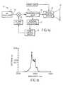
- FIG. 1 ais a schematic for an image projection system using a multi-longitudinal laser source using a radio frequency (RF) injected semiconductor laser in an image projection system.
- RFradio frequency
- FIG. 1 bis a graph of power versus wavelength for a multi-wavelength spectrum from a RF injected semiconductor laser.
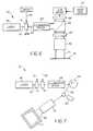
- FIG. 2 ais a schematic for an image projection system using an optical fiber to induce multi-longitudinal mode operation in a semiconductor laser.
- FIG. 2 bis a graph of power versus wavelength for a multi-wavelength spectrum from a semiconductor laser with optical feedback from an optical fiber.
- FIG. 3is a schematic for an image projection system that uses a partially reflecting mirror to induce multi-longitudinal mode operation in a laser.
- FIG. 4is a schematic for an image projection system that uses a multi-wavelength laser beam by Doppler shifting with a variable frequency acousto-optic modulator (AOM).
- AOMvariable frequency acousto-optic modulator
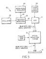
- FIG. 5is a schematic for an image projection system that uses an angularly varying laser beam by using a variable frequency AOM.
- FIG. 6is a schematic for an image projection system that uses an angularly varying beam to illuminate an area array device to project an image.
- FIG. 7is a schematic for an image projection system that uses an angularly varying beam in a raster scan laser imaging system.
- the present inventionwill be directed in particular to elements forming part of, or in cooperation more directly with, the apparatus in accordance with the present invention. It is understood that elements not specifically shown or described may take various forms well known to those skilled in the art.
- FIG. 1 ashows a laser projection system 10 comprising a radio frequency (RF) oscillator 11 driving a semiconductor laser 12 that acts as the light source for an image projection system 13 .
- the RF oscillator signal 14combined with a DC bias signal 15 , drive the semiconductor laser 12 .
- a laser beam 16 with optical power output P ois emitted from the semiconductor laser.
- a monitor beam with optical power output P mis emitted from the semiconductor laser towards an internal photodiode 17 .
- Power output P m from the semiconductor laseris monitored by the internal photodiode, and provides a signal to the control circuit 18 .
- the control circuit 18monitors the variation in the signal from the internal photodiode 17 , and adjusts the DC bias current to the semiconductor laser accordingly so as to maintain constant output power.
- a multi-wavelength laser beam 16 with power output P ois emitted from the semiconductor laser towards an optical projection system 13 .
- the injection of radio frequencychanges the laser emission from single mode to an effectively multimode pattern.
- FIG. 1 ( b )shows a graph of a multi-wavelength spectrum from an RF injected semiconductor laser. Forced multimode operation by radio frequency injection produces approximately 4 or 5 lasing modes, each of which exhibit a different speckle pattern.
- the optical projection system shown in FIG. 1 ( a )projects an image onto a projection surface, such as a screen 19 . Images projected in a projection system comprised of radio frequency injected lasers will suppress unwanted speckle patterns, since the differing speckle patterns produced by the different laser operational modes will blend together in an image.
- FIG. 2 ( a )shows a schematic for a laser projection system 20 that uses a semiconductor laser system to produce a multi-longitudinal mode output by optical feedback.
- a constant current supply 21provides a drive current for the semiconductor laser 12 .
- An optical fiber 22is positioned in front of the output beam of the laser.
- the semiconductor laser and the optical fiberare affixed to a thermoelectric cooler 23 to maintain a constant temperature for both elements.
- a temperature controller 24monitors the thermoelectric cooler and provides a drive signal to the thermoelectric cooler.
- Laser output P ois directed towards the optical fiber.
- the laser beamis primarily directed through the optical fiber to the optical projection system 13 , but a portion of the light is reflected off of the optical fiber and back into the semiconductor laser. This induces optical feedback in the laser, which in turn induces mode hopping and multi-longitudinal mode output from the semiconductor laser.
- semiconductor lasers available from Pointsourceuse a fiber pigtail to introduce optical feedback.
- FIG. 2 ( b )shows the multi-wavelength spectrum from the semiconductor laser when an optical fiber is place in front of the output of the laser.
- Optical feedbackchanges the laser emission from single mode to an effectively multimode pattern. Forced multimode operation by optical feedback produces approximately 4 or 5 lasing modes, each of which exhibit a different speckle pattern.
- the optical projection system shown in FIG. 2 ( a )projects an image onto a projection surface, such as a screen 19 . Images projected using a projection system comprised of induced multimode lasers will suppress unwanted speckle patterns, since the differing speckle patterns produced by the different laser operational modes will blend together in an image.
- FIG. 3shows a schematic for a laser projection system 30 with a laser system that produces a multi-longitudinal mode output by optical feedback.
- a laser 22is driven by a signal form a power supply 31 .
- the lasercould be a gas laser, a semiconductor laser, or a solid state laser.
- the optical output power of the laser, P ois directed towards the surface of a partially reflecting mirror 32 .
- the laser beam 33is partially transmitted through the mirror 32 towards the optical projection system 13 . However, the laser beam is also partially reflected back towards the output window of the laser. When this light reenters the laser, it disturbs the laser cavity and causes the laser to output a multi-wavelength beam.
- Optical feedbackchanges the laser emission from single mode to an effectively multimode pattern.
- the lasermay be instantaneously single mode, but it is forced to switch its mode structure rapidly. Forced multimode operation by optical feedback produces approximately 4 or 5 lasing modes, each of which exhibit a different speckle pattern.
- the multi-wavelength beamis directed towards a projection system. Because the projected beam from the optical projection system is multi-wavelength, the image formed on the imaging surface does not exhibit noticeable speckle. The varying wavelengths of the beam reduce the noticeable speckle, since the speckle patterns for each wavelength overlap and blend with each other in an image.
- FIG. 4shows a schematic for an image projection 40 that uses a multi-wavelength laser beam 16 by Doppler shifting with a variable frequency acousto-optic modulator (AOM) 41 .
- An oscillator 42is used to generate a radio frequency (RF) signal 43 .
- a modulation oscillator 44is used to generate a modulation signal.
- Both the RF signal generated by the oscillator and the modulation signalare directed into a frequency modulator 46 , which combines the signals to form a RF modulated signal 47 and directs the new signal into the AOM.
- the output of a laser 48is directed towards the AOM that is receiving the RF modulated signal.
- the multi-wavelength Doppler shifted output beam from the AOMis directed towards an optical projection system 13 .
- the projection systemprojects an image onto an imaging surface 19 . Since the input beam to the optical projection system is a multi-wavelength beam, the varying wavelengths of the beam reduce the noticeable speckle because the speckle patterns for each wavelength overlap and blend with each other in an image.
- the modulation oscillator 44need not be just a simple sinewave generating device. In order to minimize dwell at any one frequency and, therefore, the appearance of speckle, a triangle waveform is advantageous.
- FIG. 5shows a schematic for an image projection system 50 that uses an angularly varying laser beam with a variable frequency acousto-optic modulator (AOM).
- An oscillator 42is used to generate a radio frequency (RF) signal 43 .
- a modulation oscillator 44is used to generate a modulation signal 45 .
- Both the RF signal generated by the oscillator and the modulation signalare directed into a frequency modulator 46 , which combines the signals to form a RF modulated signal 47 and directs the new signal into the AOM.
- the output of a laseris directed towards the AOM 41 that is receiving the RF modulated signal.
- the AOMoutputs a beam with a small angle variation towards an optical projection system.
- the optical projection system 50outputs an angularly varying beam towards an imaging surface 19 .
- the modulation signal 45 generated by the modulation oscillator 44be a triangle wave.
- the movement of the beamneed only be approximately 1 pixel so as not to destroy the modulation transfer function (MTF) in the direction of the movement. Since the eye is very sensitive to horizontal and vertical edges, but less sensitive to angles in between, beam movement of approximately 45 degrees can minimize the perceived loss of MTF in the horizontal and vertical directions.
- the beam movement frequencymust be high enough to prevent any obvious flicker to the eye. For example, as noted in U.S. Pat. No. 5,272,473, a beam movement frequency between approximately 5 Hz and 60 Hz, depending on light level, would be sufficiently undetectable by the human eye.
- FIG. 6shows a schematic for a laser system 60 capable of generating an angularly varying beam that illuminates an area array device to project an image.
- a laser beam 61is directed towards an AOM 41 .
- a variable frequency carrier signal 62is injected into the AOM.
- the AOMoutputs an angularly varying beam 63 towards expansion optics 64 that expand the beam.
- the expanded beamis directed towards a beamsplitter cube 65 .
- a spatial light modulator 66projects an image from image data 67 provided to the spatial light modulator driver 68 .
- the beamsplitter cubeoutputs an image through an optional polarizer 69 , and then towards a projection lens 70 .
- the output of the projection lensdirects an angularly varying beam 71 towards a projection surface 19 .
- the image projected on the projection surfaceis speckle suppressed, since the angularly varying beam blends the speckle pattern of the beam with the image.
- the movement of the beamneed only be approximately 1 pixel so as not to destroy the modulation transfer function (MTF) in the direction of the movement. Since the eye is very sensitive to horizontal and vertical edges, but less sensitive to angles in between, beam movement of approximately 45 degrees may minimize the loss of MTF in the horizontal and vertical directions.
- the beam movement frequencymust be high enough to prevent any obvious flicker to the eye. For example, a beam movement frequency between approximately 5 Hz and 60 Hz would be sufficiently undetectable by the human eye.
- FIG. 6shows only a single beam projection system. Multiple beams, e.g.
- red, green and bluecan be used from separate sources and spatial light modulators and then combined using an X-cube prism, or other suitable means, for a multicolor projection system.
- X-cube prismor other suitable means, for a multicolor projection system.
- multibeam systemsin the art of incoherent color projectors.
- FIG. 7shows a schematic for a laser system 80 capable of generating an angularly varying beam in a raster scan laser system that projects an image pixel by pixel.
- the output beam 61 of a laser 48is directed towards the input of an AOM 41 .
- the AOM 41is driven by a pixel modulation signal 72 .
- the output beam of the AOM 42is directed towards another AOM 63 directly in front of the output of the first AOM, which is driven by a variable frequency carrier signal 64 .
- An angularly varying beamis outputted from the variable frequency driven AOM towards a set of optics 65 .
- the output beam from the opticsis directed towards a high speed horizontal deflector, such as a polygon 86 .
- the reflected beam 88 from the polygonis directed towards a slow speed vertical deflector 89 , such as a galvanometer or mirror.
- the reflected beam from the vertical deflectoris directed towards a projection lens 70 .
- An angularly varying output beam 90is outputted from the projection lens towards a projection surface 19 .
- the image projected on the screenis speckle suppressed, since the angularly varying beam blends the speckle pattern of the beam with the image.
- the movement of the beamneed only be approximately 1 pixel so as not to destroy the modulation transfer function (MTF) in the direction of the movement. Since the eye is very sensitive to horizontal and vertical edges, but less sensitive to angles in between, beam movement of approximately 45 degrees may minimize the loss of MTF in the horizontal and vertical directions.
- the beam movement frequencymust be high enough to prevent any obvious flicker to the eye. For example, a beam movement frequency between approximately 5 Hz and 60 Hz would be sufficiently undetectable by the human eye.
- specklemay be suppressed by the use of RF injection, optical feedback, Doppler shifted wavelength, or a deflection means suppresses speckle in a laser projection system.
- Radio frequency (RF) oscillator11 .
- RFRadio frequency
- Radio frequency (RF) signal
Landscapes
- Physics & Mathematics (AREA)
- Optics & Photonics (AREA)
- General Physics & Mathematics (AREA)
- Condensed Matter Physics & Semiconductors (AREA)
- Electromagnetism (AREA)
- Engineering & Computer Science (AREA)
- Multimedia (AREA)
- Signal Processing (AREA)
- Projection Apparatus (AREA)
- Transforming Electric Information Into Light Information (AREA)
Abstract
Description
Claims (8)
Priority Applications (1)
| Application Number | Priority Date | Filing Date | Title |
|---|---|---|---|
| US09/788,866US6625381B2 (en) | 2001-02-20 | 2001-02-20 | Speckle suppressed laser projection system with partial beam reflection |
Applications Claiming Priority (1)
| Application Number | Priority Date | Filing Date | Title |
|---|---|---|---|
| US09/788,866US6625381B2 (en) | 2001-02-20 | 2001-02-20 | Speckle suppressed laser projection system with partial beam reflection |
Publications (2)
| Publication Number | Publication Date |
|---|---|
| US20020126981A1 US20020126981A1 (en) | 2002-09-12 |
| US6625381B2true US6625381B2 (en) | 2003-09-23 |
Family
ID=25145825
Family Applications (1)
| Application Number | Title | Priority Date | Filing Date |
|---|---|---|---|
| US09/788,866Expired - LifetimeUS6625381B2 (en) | 2001-02-20 | 2001-02-20 | Speckle suppressed laser projection system with partial beam reflection |
Country Status (1)
| Country | Link |
|---|---|
| US (1) | US6625381B2 (en) |
Cited By (85)
| Publication number | Priority date | Publication date | Assignee | Title |
|---|---|---|---|---|
| US20050041000A1 (en)* | 2003-07-16 | 2005-02-24 | Plut William J. | Projection-type display devices with reduced weight and size |
| US20050057542A1 (en)* | 2003-07-16 | 2005-03-17 | Plut William J. | Positionable projection display devices |
| US20060066476A1 (en)* | 2004-09-29 | 2006-03-30 | Williams Brett A | Acousto-radio frequency modulator and applications therefore |
| US20060125969A1 (en)* | 2004-12-14 | 2006-06-15 | Chilla Juan L | Laser illuminated projection displays |
| US20060126022A1 (en)* | 2004-12-14 | 2006-06-15 | Govorkov Sergei V | Laser illuminated projection displays |
| US20060215716A1 (en)* | 2005-03-25 | 2006-09-28 | Pavilion Integration Corporation | Radio frequency modulation of variable degree and automatic power control using external photodiode sensor for low-noise lasers of various wavelengths |
| US20070070302A1 (en)* | 2005-09-29 | 2007-03-29 | Govorkov Sergei V | Speckle reduction in laser illuminated projection displays having a one-dimensional spatial light modulator |
| US20080158513A1 (en)* | 2006-12-29 | 2008-07-03 | Texas Instruments Incorporated | Apparatus and Method for Reducing Speckle In Display of Images |
| US20080212040A1 (en)* | 2007-03-02 | 2008-09-04 | Vladimir Anatolyevich Aksyuk | Holographic MEMS operated optical projectors |
| US20080212159A1 (en)* | 2007-03-02 | 2008-09-04 | Randy Clinton Giles | Direct optical image projectors |
| US20080212034A1 (en)* | 2007-03-02 | 2008-09-04 | Lucent Technologies Inc. | Speckle reduction in laser-projector images |
| US20080219303A1 (en)* | 2007-03-02 | 2008-09-11 | Lucent Technologies Inc. | Color mixing light source and color control data system |
| US20080273123A1 (en)* | 2005-09-14 | 2008-11-06 | Matsushita Electric Industrial Co., Ltd. | Laser Picture Formation Device |
| US7457330B2 (en) | 2006-06-15 | 2008-11-25 | Pavilion Integration Corporation | Low speckle noise monolithic microchip RGB lasers |
| US20090009719A1 (en)* | 2007-06-19 | 2009-01-08 | Lucent Technologies Inc. | Compact image projector |
| US20090097507A1 (en)* | 2007-10-15 | 2009-04-16 | Pavilion Integration Corporation | Wavelength and Intensity Stabilized Laser Diode and Application of Same to Pumping Solid-State Lasers |
| US20090168448A1 (en)* | 2007-12-26 | 2009-07-02 | Christie Digital Systems Usa, Inc. | Light integrator for more than one lamp |
| US20090168426A1 (en)* | 2007-12-26 | 2009-07-02 | Christie Digital Systems Usa, Inc. | Optical device for adjusting the F-number of an elliptical lamp |
| US20090185140A1 (en)* | 2008-01-22 | 2009-07-23 | Lucent Technologies, Inc. | Multi-color light source |
| US20090184659A1 (en)* | 2008-01-22 | 2009-07-23 | Gang Chen | Time division multiplexing a DC-to-DC voltage converter |
| US20090184976A1 (en)* | 2008-01-22 | 2009-07-23 | Alcatel-Lucent | System and Method for Color-Compensating a Video Signal Having Reduced Computational Requirements |
| US20090284713A1 (en)* | 2008-05-15 | 2009-11-19 | Silverstein Barry D | Uniform speckle reduced laser projection using spatial and temporal mixing |
| US20100080253A1 (en)* | 2008-09-30 | 2010-04-01 | Microvision, Inc. | Laser Display System with Optical Feedback Configured to Reduce Speckle Artifacts |
| US20100091806A1 (en)* | 2008-10-10 | 2010-04-15 | Pavilion Integration Corporation | Semiconductor Lasers with Improved Temporal, Spectral, and Spatial Stability and Beam Profile Uniformity |
| US20100165307A1 (en)* | 2005-07-28 | 2010-07-01 | Tetsuro Mizushima | Laser image display, and optical integrator and laser light source package used in such laser image display |
| US20100290009A1 (en)* | 2009-05-15 | 2010-11-18 | Alcatel-Lucent Usa Inc. | Image projector employing a speckle-reducing laser source |
| US20100321639A1 (en)* | 2009-06-22 | 2010-12-23 | Silverstein Barry D | Optical interference reducing element for laser projection |
| US20110013144A1 (en)* | 2009-07-14 | 2011-01-20 | Silverstein Barry D | Stereoscopic projector with rotating segmented disk |
| US20110234985A1 (en)* | 2010-03-26 | 2011-09-29 | Alcatel-Lucent Usa Inc. | Despeckling laser-image-projection system |
| US8059928B2 (en) | 2007-12-26 | 2011-11-15 | Christie Digital Systems Usa, Inc. | Decohered laser light production system |
| US8109638B2 (en) | 2008-01-22 | 2012-02-07 | Alcatel Lucent | Diffuser configuration for an image projector |
| US8220931B2 (en) | 2009-07-07 | 2012-07-17 | Eastman Kodak Company | Etendue reduced stereo projection using segmented disk |
| US8872985B2 (en) | 2012-04-13 | 2014-10-28 | Red.Com, Inc. | Video projector system |
| US9025086B2 (en) | 2012-04-13 | 2015-05-05 | Red.Com, Inc. | Video projector system |
| US10008822B2 (en)* | 2014-10-10 | 2018-06-26 | The Boeing Company | Laser system and method for controlling the wave front of a laser beam |
| US10089516B2 (en) | 2013-07-31 | 2018-10-02 | Digilens, Inc. | Method and apparatus for contact image sensing |
| US10145533B2 (en) | 2005-11-11 | 2018-12-04 | Digilens, Inc. | Compact holographic illumination device |
| US10156681B2 (en) | 2015-02-12 | 2018-12-18 | Digilens Inc. | Waveguide grating device |
| US10185154B2 (en) | 2011-04-07 | 2019-01-22 | Digilens, Inc. | Laser despeckler based on angular diversity |
| US10209517B2 (en) | 2013-05-20 | 2019-02-19 | Digilens, Inc. | Holographic waveguide eye tracker |
| US10216061B2 (en) | 2012-01-06 | 2019-02-26 | Digilens, Inc. | Contact image sensor using switchable bragg gratings |
| US10234696B2 (en) | 2007-07-26 | 2019-03-19 | Digilens, Inc. | Optical apparatus for recording a holographic device and method of recording |
| US10241330B2 (en) | 2014-09-19 | 2019-03-26 | Digilens, Inc. | Method and apparatus for generating input images for holographic waveguide displays |
| US10330777B2 (en) | 2015-01-20 | 2019-06-25 | Digilens Inc. | Holographic waveguide lidar |
| US10359736B2 (en) | 2014-08-08 | 2019-07-23 | Digilens Inc. | Method for holographic mastering and replication |
| US10409144B2 (en) | 2009-10-09 | 2019-09-10 | Digilens Inc. | Diffractive waveguide providing structured illumination for object detection |
| US10423222B2 (en) | 2014-09-26 | 2019-09-24 | Digilens Inc. | Holographic waveguide optical tracker |
| US10437064B2 (en) | 2015-01-12 | 2019-10-08 | Digilens Inc. | Environmentally isolated waveguide display |
| US10437051B2 (en) | 2012-05-11 | 2019-10-08 | Digilens Inc. | Apparatus for eye tracking |
| US10459145B2 (en) | 2015-03-16 | 2019-10-29 | Digilens Inc. | Waveguide device incorporating a light pipe |
| US10545346B2 (en) | 2017-01-05 | 2020-01-28 | Digilens Inc. | Wearable heads up displays |
| US10591756B2 (en) | 2015-03-31 | 2020-03-17 | Digilens Inc. | Method and apparatus for contact image sensing |
| US10642058B2 (en) | 2011-08-24 | 2020-05-05 | Digilens Inc. | Wearable data display |
| US10670876B2 (en) | 2011-08-24 | 2020-06-02 | Digilens Inc. | Waveguide laser illuminator incorporating a despeckler |
| US10678053B2 (en) | 2009-04-27 | 2020-06-09 | Digilens Inc. | Diffractive projection apparatus |
| US10690851B2 (en) | 2018-03-16 | 2020-06-23 | Digilens Inc. | Holographic waveguides incorporating birefringence control and methods for their fabrication |
| US10690916B2 (en) | 2015-10-05 | 2020-06-23 | Digilens Inc. | Apparatus for providing waveguide displays with two-dimensional pupil expansion |
| US10712640B2 (en) | 2018-05-28 | 2020-07-14 | Mcmaster University | Speckle reduced laser projection with color gamut optimization |
| US10732569B2 (en) | 2018-01-08 | 2020-08-04 | Digilens Inc. | Systems and methods for high-throughput recording of holographic gratings in waveguide cells |
| US10859768B2 (en) | 2016-03-24 | 2020-12-08 | Digilens Inc. | Method and apparatus for providing a polarization selective holographic waveguide device |
| US10890707B2 (en) | 2016-04-11 | 2021-01-12 | Digilens Inc. | Holographic waveguide apparatus for structured light projection |
| US10914950B2 (en) | 2018-01-08 | 2021-02-09 | Digilens Inc. | Waveguide architectures and related methods of manufacturing |
| US10942430B2 (en) | 2017-10-16 | 2021-03-09 | Digilens Inc. | Systems and methods for multiplying the image resolution of a pixelated display |
| US10983340B2 (en) | 2016-02-04 | 2021-04-20 | Digilens Inc. | Holographic waveguide optical tracker |
| US11204540B2 (en) | 2009-10-09 | 2021-12-21 | Digilens Inc. | Diffractive waveguide providing a retinal image |
| US11307432B2 (en) | 2014-08-08 | 2022-04-19 | Digilens Inc. | Waveguide laser illuminator incorporating a Despeckler |
| US11378732B2 (en) | 2019-03-12 | 2022-07-05 | DigLens Inc. | Holographic waveguide backlight and related methods of manufacturing |
| US11402801B2 (en) | 2018-07-25 | 2022-08-02 | Digilens Inc. | Systems and methods for fabricating a multilayer optical structure |
| US11442222B2 (en) | 2019-08-29 | 2022-09-13 | Digilens Inc. | Evacuated gratings and methods of manufacturing |
| US11448937B2 (en) | 2012-11-16 | 2022-09-20 | Digilens Inc. | Transparent waveguide display for tiling a display having plural optical powers using overlapping and offset FOV tiles |
| US11460621B2 (en) | 2012-04-25 | 2022-10-04 | Rockwell Collins, Inc. | Holographic wide angle display |
| US11480788B2 (en) | 2015-01-12 | 2022-10-25 | Digilens Inc. | Light field displays incorporating holographic waveguides |
| US11513350B2 (en) | 2016-12-02 | 2022-11-29 | Digilens Inc. | Waveguide device with uniform output illumination |
| US11543594B2 (en) | 2019-02-15 | 2023-01-03 | Digilens Inc. | Methods and apparatuses for providing a holographic waveguide display using integrated gratings |
| US11681143B2 (en) | 2019-07-29 | 2023-06-20 | Digilens Inc. | Methods and apparatus for multiplying the image resolution and field-of-view of a pixelated display |
| US11726332B2 (en) | 2009-04-27 | 2023-08-15 | Digilens Inc. | Diffractive projection apparatus |
| US11747568B2 (en) | 2019-06-07 | 2023-09-05 | Digilens Inc. | Waveguides incorporating transmissive and reflective gratings and related methods of manufacturing |
| US12092914B2 (en) | 2018-01-08 | 2024-09-17 | Digilens Inc. | Systems and methods for manufacturing waveguide cells |
| US12140764B2 (en) | 2019-02-15 | 2024-11-12 | Digilens Inc. | Wide angle waveguide display |
| US12158612B2 (en) | 2021-03-05 | 2024-12-03 | Digilens Inc. | Evacuated periodic structures and methods of manufacturing |
| US12210153B2 (en) | 2019-01-14 | 2025-01-28 | Digilens Inc. | Holographic waveguide display with light control layer |
| US12222499B2 (en) | 2020-12-21 | 2025-02-11 | Digilens Inc. | Eye glow suppression in waveguide based displays |
| US12306585B2 (en) | 2018-01-08 | 2025-05-20 | Digilens Inc. | Methods for fabricating optical waveguides |
| US12397477B2 (en) | 2019-02-05 | 2025-08-26 | Digilens Inc. | Methods for compensating for optical surface nonuniformity |
| US12399326B2 (en) | 2021-01-07 | 2025-08-26 | Digilens Inc. | Grating structures for color waveguides |
Families Citing this family (17)
| Publication number | Priority date | Publication date | Assignee | Title |
|---|---|---|---|---|
| WO2004031753A1 (en)* | 2002-09-30 | 2004-04-15 | Applied Materials Israel, Ltd. | Inspection system with oblique viewing angle |
| ATE391309T1 (en)* | 2004-08-30 | 2008-04-15 | Koninkl Philips Electronics Nv | LASER PROJECTION SYSTEM |
| US7620091B2 (en)* | 2005-05-31 | 2009-11-17 | Koninklijke Philips Electronics N.V. | Broadband laser lamp with reduced speckle |
| KR100803222B1 (en) | 2007-01-26 | 2008-02-14 | 삼성전자주식회사 | Speckle Reduction Laser and Laser Display Device |
| US9939653B2 (en) | 2009-12-07 | 2018-04-10 | Projection Ventures Inc. | Despeckling stability |
| EP2510595A2 (en)* | 2009-12-07 | 2012-10-17 | Barret Lippey | Despeckling apparatus and method |
| DE102012201492A1 (en)* | 2012-02-02 | 2013-08-08 | Robert Bosch Gmbh | Drive device for a laser diode, laser projection system and method for speckle reduction in a laser diode |
| CN104901154A (en)* | 2015-05-07 | 2015-09-09 | 中国科学院物理研究所 | Laser spreading device and method based on white Gaussian noise |
| US9413372B1 (en)* | 2015-07-30 | 2016-08-09 | The Aerospace Corporation | Systems and methods for converting radio frequency signals into the digital domain using multi-mode optics |
| US10673457B2 (en) | 2016-04-04 | 2020-06-02 | The Aerospace Corporation | Systems and methods for detecting events that are sparse in time |
| CN106451069A (en)* | 2016-09-12 | 2017-02-22 | 无锡迈微光电科技有限公司 | Method for reducing self-mixed interference effect of laser system |
| CN106451070A (en)* | 2016-09-12 | 2017-02-22 | 无锡迈微光电科技有限公司 | Method for reducing etalon effect of laser device system |
| US10095262B2 (en) | 2016-12-12 | 2018-10-09 | The Aerospace Corporation | Systems and methods for performing linear algebra operations using multi-mode optics |
| EP4328656A3 (en) | 2017-07-06 | 2024-05-15 | Magic Leap, Inc. | Speckle-reduction in virtual and augmented reality systems and methods |
| CN108445702A (en)* | 2018-05-18 | 2018-08-24 | 中国科学院理化技术研究所 | Laser projection device and laser beam modulation method |
| US10627849B1 (en) | 2018-10-08 | 2020-04-21 | The Aerospace Corporation | Reservoir computing operations using multi-mode photonic integrated circuits |
| CN114265196B (en)* | 2021-12-10 | 2023-09-05 | 无锡微视传感科技有限公司 | MEMS micro-galvanometer-based optical path structure and speckle eliminating method thereof |
Citations (9)
| Publication number | Priority date | Publication date | Assignee | Title |
|---|---|---|---|---|
| US4011403A (en) | 1976-03-30 | 1977-03-08 | Northwestern University | Fiber optic laser illuminators |
| US4155630A (en) | 1977-11-17 | 1979-05-22 | University Of Delaware | Speckle elimination by random spatial phase modulation |
| US5272473A (en) | 1989-02-27 | 1993-12-21 | Texas Instruments Incorporated | Reduced-speckle display system |
| US5274494A (en) | 1991-04-25 | 1993-12-28 | Hughes Aircraft Company | Speckle suppression illuminator |
| US5313479A (en) | 1992-07-29 | 1994-05-17 | Texas Instruments Incorporated | Speckle-free display system using coherent light |
| US5453814A (en) | 1994-04-13 | 1995-09-26 | Nikon Precision Inc. | Illumination source and method for microlithography |
| US5682398A (en)* | 1996-05-03 | 1997-10-28 | Eastman Kodak Company | Frequency conversion laser devices |
| US6363088B1 (en)* | 1998-11-30 | 2002-03-26 | Sarnoff Corporation | All solid-state power broadband visible light source |
| US6470122B1 (en)* | 1998-05-20 | 2002-10-22 | Sony Corporation | Optical coherence reduction method and device, illuminating method and system |
- 2001
- 2001-02-20USUS09/788,866patent/US6625381B2/ennot_activeExpired - Lifetime
Patent Citations (9)
| Publication number | Priority date | Publication date | Assignee | Title |
|---|---|---|---|---|
| US4011403A (en) | 1976-03-30 | 1977-03-08 | Northwestern University | Fiber optic laser illuminators |
| US4155630A (en) | 1977-11-17 | 1979-05-22 | University Of Delaware | Speckle elimination by random spatial phase modulation |
| US5272473A (en) | 1989-02-27 | 1993-12-21 | Texas Instruments Incorporated | Reduced-speckle display system |
| US5274494A (en) | 1991-04-25 | 1993-12-28 | Hughes Aircraft Company | Speckle suppression illuminator |
| US5313479A (en) | 1992-07-29 | 1994-05-17 | Texas Instruments Incorporated | Speckle-free display system using coherent light |
| US5453814A (en) | 1994-04-13 | 1995-09-26 | Nikon Precision Inc. | Illumination source and method for microlithography |
| US5682398A (en)* | 1996-05-03 | 1997-10-28 | Eastman Kodak Company | Frequency conversion laser devices |
| US6470122B1 (en)* | 1998-05-20 | 2002-10-22 | Sony Corporation | Optical coherence reduction method and device, illuminating method and system |
| US6363088B1 (en)* | 1998-11-30 | 2002-03-26 | Sarnoff Corporation | All solid-state power broadband visible light source |
Cited By (166)
| Publication number | Priority date | Publication date | Assignee | Title |
|---|---|---|---|---|
| US20070205300A1 (en)* | 2003-07-16 | 2007-09-06 | Plut William J | Positioning interfaces for projection display devices |
| US7281807B2 (en) | 2003-07-16 | 2007-10-16 | Honeywood Technologies, Llc | Positionable projection display devices |
| US8366282B2 (en) | 2003-07-16 | 2013-02-05 | Transpacific Image, Llc | Positioning interfaces for projection display devices |
| US8147074B2 (en) | 2003-07-16 | 2012-04-03 | Transpacific Image, Llc | Positioning interfaces for projection display devices |
| US8641209B2 (en) | 2003-07-16 | 2014-02-04 | Transpacific Image, Llc | Positioning interfaces for projection display devices |
| US7703930B2 (en) | 2003-07-16 | 2010-04-27 | Plut William J | Positioning interfaces for projection display devices |
| US7156522B2 (en) | 2003-07-16 | 2007-01-02 | Plut William J | Projection-type display devices with reduced weight and size |
| US20100171936A1 (en)* | 2003-07-16 | 2010-07-08 | Plut William J | Positioning interfaces for projection display devices |
| US7510284B2 (en) | 2003-07-16 | 2009-03-31 | Plut William J | Projection-type display devices including redundant laser sets |
| US20050041000A1 (en)* | 2003-07-16 | 2005-02-24 | Plut William J. | Projection-type display devices with reduced weight and size |
| US20050057542A1 (en)* | 2003-07-16 | 2005-03-17 | Plut William J. | Positionable projection display devices |
| USRE42251E1 (en)* | 2003-07-16 | 2011-03-29 | Transpacific Image, Llc | Projection-type display devices with reduced weight and size |
| US20070195276A1 (en)* | 2003-07-16 | 2007-08-23 | Plut William J | Projection-type display devices with reduced speckle |
| US7806535B2 (en) | 2003-07-16 | 2010-10-05 | Plut William J | Low power projection display devices |
| US7295153B2 (en)* | 2004-09-29 | 2007-11-13 | Lockheed Martin Corporation | Acousto-radio frequency modulator and applications therefore |
| US20060066476A1 (en)* | 2004-09-29 | 2006-03-30 | Williams Brett A | Acousto-radio frequency modulator and applications therefore |
| US20080143888A1 (en)* | 2004-12-14 | 2008-06-19 | Chilla Juan L | Laser illuminated projection displays |
| US7355657B2 (en) | 2004-12-14 | 2008-04-08 | Coherent, Inc. | Laser illuminated projection displays |
| US7633562B2 (en) | 2004-12-14 | 2009-12-15 | Coherent, Inc. | Laser illuminated projection displays |
| US7244028B2 (en) | 2004-12-14 | 2007-07-17 | Coherent, Inc. | Laser illuminated projection displays |
| US20060126022A1 (en)* | 2004-12-14 | 2006-06-15 | Govorkov Sergei V | Laser illuminated projection displays |
| US20060125969A1 (en)* | 2004-12-14 | 2006-06-15 | Chilla Juan L | Laser illuminated projection displays |
| US7468998B2 (en) | 2005-03-25 | 2008-12-23 | Pavilion Integration Corporation | Radio frequency modulation of variable degree and automatic power control using external photodiode sensor for low-noise lasers of various wavelengths |
| US20060215716A1 (en)* | 2005-03-25 | 2006-09-28 | Pavilion Integration Corporation | Radio frequency modulation of variable degree and automatic power control using external photodiode sensor for low-noise lasers of various wavelengths |
| US7954962B2 (en)* | 2005-07-28 | 2011-06-07 | Panasonic Corporation | Laser image display, and optical integrator and laser light source package used in such laser image display |
| US20100165307A1 (en)* | 2005-07-28 | 2010-07-01 | Tetsuro Mizushima | Laser image display, and optical integrator and laser light source package used in such laser image display |
| US20080273123A1 (en)* | 2005-09-14 | 2008-11-06 | Matsushita Electric Industrial Co., Ltd. | Laser Picture Formation Device |
| US7413311B2 (en) | 2005-09-29 | 2008-08-19 | Coherent, Inc. | Speckle reduction in laser illuminated projection displays having a one-dimensional spatial light modulator |
| US20070070302A1 (en)* | 2005-09-29 | 2007-03-29 | Govorkov Sergei V | Speckle reduction in laser illuminated projection displays having a one-dimensional spatial light modulator |
| US10145533B2 (en) | 2005-11-11 | 2018-12-04 | Digilens, Inc. | Compact holographic illumination device |
| US7457330B2 (en) | 2006-06-15 | 2008-11-25 | Pavilion Integration Corporation | Low speckle noise monolithic microchip RGB lasers |
| US8556431B2 (en)* | 2006-12-29 | 2013-10-15 | Texas Instruments Incorporated | Apparatus and method for reducing speckle in display of images |
| US20110261328A1 (en)* | 2006-12-29 | 2011-10-27 | Texas Instruments Incorporated | Apparatus and Method for Reducing Speckle in Display of Images |
| US7972020B2 (en)* | 2006-12-29 | 2011-07-05 | Texas Instruments Incorporated | Apparatus and method for reducing speckle in display of images |
| US20080158513A1 (en)* | 2006-12-29 | 2008-07-03 | Texas Instruments Incorporated | Apparatus and Method for Reducing Speckle In Display of Images |
| US20080219303A1 (en)* | 2007-03-02 | 2008-09-11 | Lucent Technologies Inc. | Color mixing light source and color control data system |
| US20080212040A1 (en)* | 2007-03-02 | 2008-09-04 | Vladimir Anatolyevich Aksyuk | Holographic MEMS operated optical projectors |
| US7502160B2 (en) | 2007-03-02 | 2009-03-10 | Alcatel-Lucent Usa Inc. | Speckle reduction in laser-projector images |
| US20080212159A1 (en)* | 2007-03-02 | 2008-09-04 | Randy Clinton Giles | Direct optical image projectors |
| US9778477B2 (en) | 2007-03-02 | 2017-10-03 | Alcatel-Lucent Usa Inc. | Holographic MEMS operated optical projectors |
| US20080212034A1 (en)* | 2007-03-02 | 2008-09-04 | Lucent Technologies Inc. | Speckle reduction in laser-projector images |
| US7440158B2 (en) | 2007-03-02 | 2008-10-21 | Lucent Technologies Inc. | Direct optical image projectors |
| US20090009719A1 (en)* | 2007-06-19 | 2009-01-08 | Lucent Technologies Inc. | Compact image projector |
| US7750286B2 (en) | 2007-06-19 | 2010-07-06 | Alcatel-Lucent Usa Inc. | Compact image projector having a mirror for reflecting a beam received from a polarization beam splitter back to the polarization beam splitter |
| US10234696B2 (en) | 2007-07-26 | 2019-03-19 | Digilens, Inc. | Optical apparatus for recording a holographic device and method of recording |
| US10725312B2 (en) | 2007-07-26 | 2020-07-28 | Digilens Inc. | Laser illumination device |
| US7606273B2 (en) | 2007-10-15 | 2009-10-20 | Pavilion Integration Corporation | Wavelength and intensity stabilized laser diode and application of same to pumping solid-state lasers |
| US20090097507A1 (en)* | 2007-10-15 | 2009-04-16 | Pavilion Integration Corporation | Wavelength and Intensity Stabilized Laser Diode and Application of Same to Pumping Solid-State Lasers |
| US7712924B2 (en) | 2007-12-26 | 2010-05-11 | Christie Digital Systems Usa, Inc. | Optical device for adjusting the F-number of an elliptical lamp |
| US20090168448A1 (en)* | 2007-12-26 | 2009-07-02 | Christie Digital Systems Usa, Inc. | Light integrator for more than one lamp |
| US20090168426A1 (en)* | 2007-12-26 | 2009-07-02 | Christie Digital Systems Usa, Inc. | Optical device for adjusting the F-number of an elliptical lamp |
| US8965161B2 (en) | 2007-12-26 | 2015-02-24 | Christie Digital Systems Inc. | Decohered laser light production system |
| US8059928B2 (en) | 2007-12-26 | 2011-11-15 | Christie Digital Systems Usa, Inc. | Decohered laser light production system |
| US8011810B2 (en) | 2007-12-26 | 2011-09-06 | Christie Digital Systems Usa, Inc. | Light integrator for more than one lamp |
| US8129669B2 (en) | 2008-01-22 | 2012-03-06 | Alcatel Lucent | System and method generating multi-color light for image display having a controller for temporally interleaving the first and second time intervals of directed first and second light beams |
| US20090185140A1 (en)* | 2008-01-22 | 2009-07-23 | Lucent Technologies, Inc. | Multi-color light source |
| US20090184659A1 (en)* | 2008-01-22 | 2009-07-23 | Gang Chen | Time division multiplexing a DC-to-DC voltage converter |
| US20090184976A1 (en)* | 2008-01-22 | 2009-07-23 | Alcatel-Lucent | System and Method for Color-Compensating a Video Signal Having Reduced Computational Requirements |
| US8247999B2 (en) | 2008-01-22 | 2012-08-21 | Alcatel Lucent | Time division multiplexing a DC-to-DC voltage converter |
| US8109638B2 (en) | 2008-01-22 | 2012-02-07 | Alcatel Lucent | Diffuser configuration for an image projector |
| US7959297B2 (en) | 2008-05-15 | 2011-06-14 | Eastman Kodak Company | Uniform speckle reduced laser projection using spatial and temporal mixing |
| US20090284713A1 (en)* | 2008-05-15 | 2009-11-19 | Silverstein Barry D | Uniform speckle reduced laser projection using spatial and temporal mixing |
| US8070298B2 (en) | 2008-09-30 | 2011-12-06 | Microvision, Inc. | Laser display system with optical feedback configured to reduce speckle artifacts |
| US20100080253A1 (en)* | 2008-09-30 | 2010-04-01 | Microvision, Inc. | Laser Display System with Optical Feedback Configured to Reduce Speckle Artifacts |
| US7993012B2 (en)* | 2008-09-30 | 2011-08-09 | Microvision, Inc. | Laser display system with optical feedback configured to reduce speckle artifacts |
| US20110205504A1 (en)* | 2008-09-30 | 2011-08-25 | Microvision, Inc. | Laser Display System with Optical Feedback Configured to Reduce Speckle Artifacts |
| US20100091806A1 (en)* | 2008-10-10 | 2010-04-15 | Pavilion Integration Corporation | Semiconductor Lasers with Improved Temporal, Spectral, and Spatial Stability and Beam Profile Uniformity |
| US10678053B2 (en) | 2009-04-27 | 2020-06-09 | Digilens Inc. | Diffractive projection apparatus |
| US11726332B2 (en) | 2009-04-27 | 2023-08-15 | Digilens Inc. | Diffractive projection apparatus |
| US11175512B2 (en) | 2009-04-27 | 2021-11-16 | Digilens Inc. | Diffractive projection apparatus |
| US8226241B2 (en) | 2009-05-15 | 2012-07-24 | Alcatel Lucent | Image projector employing a speckle-reducing laser source |
| US20100290009A1 (en)* | 2009-05-15 | 2010-11-18 | Alcatel-Lucent Usa Inc. | Image projector employing a speckle-reducing laser source |
| US20100321639A1 (en)* | 2009-06-22 | 2010-12-23 | Silverstein Barry D | Optical interference reducing element for laser projection |
| US8235531B2 (en) | 2009-06-22 | 2012-08-07 | Eastman Kodak Company | Optical interference reducing element for laser projection |
| US8220931B2 (en) | 2009-07-07 | 2012-07-17 | Eastman Kodak Company | Etendue reduced stereo projection using segmented disk |
| US20110013144A1 (en)* | 2009-07-14 | 2011-01-20 | Silverstein Barry D | Stereoscopic projector with rotating segmented disk |
| US8066382B2 (en) | 2009-07-14 | 2011-11-29 | Eastman Kodak Company | Stereoscopic projector with rotating segmented disk |
| US11204540B2 (en) | 2009-10-09 | 2021-12-21 | Digilens Inc. | Diffractive waveguide providing a retinal image |
| US10409144B2 (en) | 2009-10-09 | 2019-09-10 | Digilens Inc. | Diffractive waveguide providing structured illumination for object detection |
| US20110234985A1 (en)* | 2010-03-26 | 2011-09-29 | Alcatel-Lucent Usa Inc. | Despeckling laser-image-projection system |
| US11487131B2 (en) | 2011-04-07 | 2022-11-01 | Digilens Inc. | Laser despeckler based on angular diversity |
| US10185154B2 (en) | 2011-04-07 | 2019-01-22 | Digilens, Inc. | Laser despeckler based on angular diversity |
| US10670876B2 (en) | 2011-08-24 | 2020-06-02 | Digilens Inc. | Waveguide laser illuminator incorporating a despeckler |
| US12306418B2 (en) | 2011-08-24 | 2025-05-20 | Rockwell Collins, Inc. | Wearable data display |
| US11287666B2 (en) | 2011-08-24 | 2022-03-29 | Digilens, Inc. | Wearable data display |
| US10642058B2 (en) | 2011-08-24 | 2020-05-05 | Digilens Inc. | Wearable data display |
| US10216061B2 (en) | 2012-01-06 | 2019-02-26 | Digilens, Inc. | Contact image sensor using switchable bragg gratings |
| US10459311B2 (en) | 2012-01-06 | 2019-10-29 | Digilens Inc. | Contact image sensor using switchable Bragg gratings |
| US11256155B2 (en) | 2012-01-06 | 2022-02-22 | Digilens Inc. | Contact image sensor using switchable Bragg gratings |
| US9106843B2 (en) | 2012-04-13 | 2015-08-11 | Red.Com, Inc. | Video projector system |
| US9025086B2 (en) | 2012-04-13 | 2015-05-05 | Red.Com, Inc. | Video projector system |
| US8872985B2 (en) | 2012-04-13 | 2014-10-28 | Red.Com, Inc. | Video projector system |
| US9854214B2 (en) | 2012-04-13 | 2017-12-26 | Red.Com, Llc | Video projector system |
| US9319648B2 (en) | 2012-04-13 | 2016-04-19 | Red.Com, Inc. | Video projector system |
| US10499024B2 (en) | 2012-04-13 | 2019-12-03 | Red.Com, Llc | Video projector system |
| US11460621B2 (en) | 2012-04-25 | 2022-10-04 | Rockwell Collins, Inc. | Holographic wide angle display |
| US10437051B2 (en) | 2012-05-11 | 2019-10-08 | Digilens Inc. | Apparatus for eye tracking |
| US11994674B2 (en) | 2012-05-11 | 2024-05-28 | Digilens Inc. | Apparatus for eye tracking |
| US20230114549A1 (en)* | 2012-11-16 | 2023-04-13 | Rockwell Collins, Inc. | Transparent waveguide display |
| US12405507B2 (en) | 2012-11-16 | 2025-09-02 | Digilens Inc. | Transparent waveguide display with grating lamina that both couple and extract modulated light |
| US11448937B2 (en) | 2012-11-16 | 2022-09-20 | Digilens Inc. | Transparent waveguide display for tiling a display having plural optical powers using overlapping and offset FOV tiles |
| US11815781B2 (en)* | 2012-11-16 | 2023-11-14 | Rockwell Collins, Inc. | Transparent waveguide display |
| US11662590B2 (en) | 2013-05-20 | 2023-05-30 | Digilens Inc. | Holographic waveguide eye tracker |
| US10209517B2 (en) | 2013-05-20 | 2019-02-19 | Digilens, Inc. | Holographic waveguide eye tracker |
| US10423813B2 (en) | 2013-07-31 | 2019-09-24 | Digilens Inc. | Method and apparatus for contact image sensing |
| US10089516B2 (en) | 2013-07-31 | 2018-10-02 | Digilens, Inc. | Method and apparatus for contact image sensing |
| US11709373B2 (en) | 2014-08-08 | 2023-07-25 | Digilens Inc. | Waveguide laser illuminator incorporating a despeckler |
| US10359736B2 (en) | 2014-08-08 | 2019-07-23 | Digilens Inc. | Method for holographic mastering and replication |
| US11307432B2 (en) | 2014-08-08 | 2022-04-19 | Digilens Inc. | Waveguide laser illuminator incorporating a Despeckler |
| US11726323B2 (en) | 2014-09-19 | 2023-08-15 | Digilens Inc. | Method and apparatus for generating input images for holographic waveguide displays |
| US10241330B2 (en) | 2014-09-19 | 2019-03-26 | Digilens, Inc. | Method and apparatus for generating input images for holographic waveguide displays |
| US10423222B2 (en) | 2014-09-26 | 2019-09-24 | Digilens Inc. | Holographic waveguide optical tracker |
| US10008822B2 (en)* | 2014-10-10 | 2018-06-26 | The Boeing Company | Laser system and method for controlling the wave front of a laser beam |
| US11726329B2 (en) | 2015-01-12 | 2023-08-15 | Digilens Inc. | Environmentally isolated waveguide display |
| US11480788B2 (en) | 2015-01-12 | 2022-10-25 | Digilens Inc. | Light field displays incorporating holographic waveguides |
| US10437064B2 (en) | 2015-01-12 | 2019-10-08 | Digilens Inc. | Environmentally isolated waveguide display |
| US11740472B2 (en) | 2015-01-12 | 2023-08-29 | Digilens Inc. | Environmentally isolated waveguide display |
| US10330777B2 (en) | 2015-01-20 | 2019-06-25 | Digilens Inc. | Holographic waveguide lidar |
| US10156681B2 (en) | 2015-02-12 | 2018-12-18 | Digilens Inc. | Waveguide grating device |
| US12379547B2 (en) | 2015-02-12 | 2025-08-05 | Digilens Inc. | Waveguide grating device |
| US11703645B2 (en) | 2015-02-12 | 2023-07-18 | Digilens Inc. | Waveguide grating device |
| US10527797B2 (en) | 2015-02-12 | 2020-01-07 | Digilens Inc. | Waveguide grating device |
| US12013561B2 (en) | 2015-03-16 | 2024-06-18 | Digilens Inc. | Waveguide device incorporating a light pipe |
| US10459145B2 (en) | 2015-03-16 | 2019-10-29 | Digilens Inc. | Waveguide device incorporating a light pipe |
| US10591756B2 (en) | 2015-03-31 | 2020-03-17 | Digilens Inc. | Method and apparatus for contact image sensing |
| US11754842B2 (en) | 2015-10-05 | 2023-09-12 | Digilens Inc. | Apparatus for providing waveguide displays with two-dimensional pupil expansion |
| US11281013B2 (en) | 2015-10-05 | 2022-03-22 | Digilens Inc. | Apparatus for providing waveguide displays with two-dimensional pupil expansion |
| US12405471B2 (en) | 2015-10-05 | 2025-09-02 | Digilens Inc. | Apparatus for providing waveguide displays with two-dimensional pupil expansion |
| US10690916B2 (en) | 2015-10-05 | 2020-06-23 | Digilens Inc. | Apparatus for providing waveguide displays with two-dimensional pupil expansion |
| US10983340B2 (en) | 2016-02-04 | 2021-04-20 | Digilens Inc. | Holographic waveguide optical tracker |
| US10859768B2 (en) | 2016-03-24 | 2020-12-08 | Digilens Inc. | Method and apparatus for providing a polarization selective holographic waveguide device |
| US11604314B2 (en) | 2016-03-24 | 2023-03-14 | Digilens Inc. | Method and apparatus for providing a polarization selective holographic waveguide device |
| US10890707B2 (en) | 2016-04-11 | 2021-01-12 | Digilens Inc. | Holographic waveguide apparatus for structured light projection |
| US12298513B2 (en) | 2016-12-02 | 2025-05-13 | Digilens Inc. | Waveguide device with uniform output illumination |
| US11513350B2 (en) | 2016-12-02 | 2022-11-29 | Digilens Inc. | Waveguide device with uniform output illumination |
| US10545346B2 (en) | 2017-01-05 | 2020-01-28 | Digilens Inc. | Wearable heads up displays |
| US11194162B2 (en) | 2017-01-05 | 2021-12-07 | Digilens Inc. | Wearable heads up displays |
| US12248150B2 (en) | 2017-01-05 | 2025-03-11 | Digilens Inc. | Wearable heads up displays |
| US11586046B2 (en) | 2017-01-05 | 2023-02-21 | Digilens Inc. | Wearable heads up displays |
| US10942430B2 (en) | 2017-10-16 | 2021-03-09 | Digilens Inc. | Systems and methods for multiplying the image resolution of a pixelated display |
| US11573483B2 (en) | 2017-10-16 | 2023-02-07 | Digilens Inc. | Systems and methods for multiplying the image resolution of a pixelated display |
| US12306585B2 (en) | 2018-01-08 | 2025-05-20 | Digilens Inc. | Methods for fabricating optical waveguides |
| US10732569B2 (en) | 2018-01-08 | 2020-08-04 | Digilens Inc. | Systems and methods for high-throughput recording of holographic gratings in waveguide cells |
| US12366823B2 (en) | 2018-01-08 | 2025-07-22 | Digilens Inc. | Systems and methods for high-throughput recording of holographic gratings in waveguide cells |
| US12352960B2 (en) | 2018-01-08 | 2025-07-08 | Digilens Inc. | Waveguide architectures and related methods of manufacturing |
| US10914950B2 (en) | 2018-01-08 | 2021-02-09 | Digilens Inc. | Waveguide architectures and related methods of manufacturing |
| US12092914B2 (en) | 2018-01-08 | 2024-09-17 | Digilens Inc. | Systems and methods for manufacturing waveguide cells |
| US11150408B2 (en) | 2018-03-16 | 2021-10-19 | Digilens Inc. | Holographic waveguides incorporating birefringence control and methods for their fabrication |
| US10690851B2 (en) | 2018-03-16 | 2020-06-23 | Digilens Inc. | Holographic waveguides incorporating birefringence control and methods for their fabrication |
| US11726261B2 (en) | 2018-03-16 | 2023-08-15 | Digilens Inc. | Holographic waveguides incorporating birefringence control and methods for their fabrication |
| US10712640B2 (en) | 2018-05-28 | 2020-07-14 | Mcmaster University | Speckle reduced laser projection with color gamut optimization |
| US11402801B2 (en) | 2018-07-25 | 2022-08-02 | Digilens Inc. | Systems and methods for fabricating a multilayer optical structure |
| US12210153B2 (en) | 2019-01-14 | 2025-01-28 | Digilens Inc. | Holographic waveguide display with light control layer |
| US12397477B2 (en) | 2019-02-05 | 2025-08-26 | Digilens Inc. | Methods for compensating for optical surface nonuniformity |
| US11543594B2 (en) | 2019-02-15 | 2023-01-03 | Digilens Inc. | Methods and apparatuses for providing a holographic waveguide display using integrated gratings |
| US12140764B2 (en) | 2019-02-15 | 2024-11-12 | Digilens Inc. | Wide angle waveguide display |
| US11378732B2 (en) | 2019-03-12 | 2022-07-05 | DigLens Inc. | Holographic waveguide backlight and related methods of manufacturing |
| US11747568B2 (en) | 2019-06-07 | 2023-09-05 | Digilens Inc. | Waveguides incorporating transmissive and reflective gratings and related methods of manufacturing |
| US12271035B2 (en) | 2019-06-07 | 2025-04-08 | Digilens Inc. | Waveguides incorporating transmissive and reflective gratings and related methods of manufacturing |
| US11681143B2 (en) | 2019-07-29 | 2023-06-20 | Digilens Inc. | Methods and apparatus for multiplying the image resolution and field-of-view of a pixelated display |
| US11442222B2 (en) | 2019-08-29 | 2022-09-13 | Digilens Inc. | Evacuated gratings and methods of manufacturing |
| US11592614B2 (en) | 2019-08-29 | 2023-02-28 | Digilens Inc. | Evacuated gratings and methods of manufacturing |
| US11899238B2 (en) | 2019-08-29 | 2024-02-13 | Digilens Inc. | Evacuated gratings and methods of manufacturing |
| US12222499B2 (en) | 2020-12-21 | 2025-02-11 | Digilens Inc. | Eye glow suppression in waveguide based displays |
| US12399326B2 (en) | 2021-01-07 | 2025-08-26 | Digilens Inc. | Grating structures for color waveguides |
| US12158612B2 (en) | 2021-03-05 | 2024-12-03 | Digilens Inc. | Evacuated periodic structures and methods of manufacturing |
Also Published As
| Publication number | Publication date |
|---|---|
| US20020126981A1 (en) | 2002-09-12 |
Similar Documents
| Publication | Publication Date | Title |
|---|---|---|
| US6625381B2 (en) | Speckle suppressed laser projection system with partial beam reflection | |
| US6600590B2 (en) | Speckle suppressed laser projection system using RF injection | |
| US6445487B1 (en) | Speckle suppressed laser projection system using a multi-wavelength doppler shifted beam | |
| US7677736B2 (en) | Illumination light source and two-dimensional image display using same | |
| US7370973B2 (en) | Displaying optical system and image projection apparatus | |
| US8350789B2 (en) | Image display apparatus | |
| CN101018345B (en) | Laser display device | |
| US8066385B2 (en) | Projection display and lighting unit with diffusion optical device | |
| TW202034023A (en) | Image projector | |
| US7679799B2 (en) | Illuminating light source including a light intensity modulator that oscillates a light from a coherent light source in a non-integral multiple of one cycle and two- dimensional image display using the same | |
| US8226241B2 (en) | Image projector employing a speckle-reducing laser source | |
| US7414621B2 (en) | Method and apparatus for controllably producing a laser display | |
| JP2003279889A (en) | Laser projection display system | |
| WO2011046034A1 (en) | Image projection device, image projection method and image display device | |
| KR20220084159A (en) | Laser illuminated display with improved uniformity and/or improved eye protection | |
| US7095541B2 (en) | Method of generating area light source by scanning, scanning area light source and laser projection television using the same | |
| US5687020A (en) | Image projector using acousto-optic tunable filter | |
| EP3538953B1 (en) | Rgb projector with multi-laser broadband light source and method for dynamically controlling image contrast ratio | |
| US7817324B2 (en) | Projector | |
| US11442335B2 (en) | Systems and methods for managing incoherent laser beams | |
| JP5401813B2 (en) | Image display device | |
| US20160323550A1 (en) | Scanned light beam video projection system and method, automotive vehicle head-up display and adaptive lighting device using such a system | |
| JP2003308047A (en) | Active display system | |
| KR101099327B1 (en) | Laser light source and scanning display apparatus having the same | |
| JP2015129784A (en) | Projection type display device |
Legal Events
| Date | Code | Title | Description |
|---|---|---|---|
| AS | Assignment | Owner name:EASTMAN KODAK COMPANY, NEW YORK Free format text:ASSIGNMENT OF ASSIGNORS INTEREST;ASSIGNORS:RODDY, JAMES E.;MARKIS, WILLIAM R.;REEL/FRAME:011597/0962 Effective date:20010219 | |
| STCF | Information on status: patent grant | Free format text:PATENTED CASE | |
| FEPP | Fee payment procedure | Free format text:PAYOR NUMBER ASSIGNED (ORIGINAL EVENT CODE: ASPN); ENTITY STATUS OF PATENT OWNER: LARGE ENTITY | |
| FPAY | Fee payment | Year of fee payment:4 | |
| FPAY | Fee payment | Year of fee payment:8 | |
| AS | Assignment | Owner name:CITICORP NORTH AMERICA, INC., AS AGENT, NEW YORK Free format text:SECURITY INTEREST;ASSIGNORS:EASTMAN KODAK COMPANY;PAKON, INC.;REEL/FRAME:028201/0420 Effective date:20120215 | |
| AS | Assignment | Owner name:WILMINGTON TRUST, NATIONAL ASSOCIATION, AS AGENT, Free format text:PATENT SECURITY AGREEMENT;ASSIGNORS:EASTMAN KODAK COMPANY;PAKON, INC.;REEL/FRAME:030122/0235 Effective date:20130322 Owner name:WILMINGTON TRUST, NATIONAL ASSOCIATION, AS AGENT, MINNESOTA Free format text:PATENT SECURITY AGREEMENT;ASSIGNORS:EASTMAN KODAK COMPANY;PAKON, INC.;REEL/FRAME:030122/0235 Effective date:20130322 | |
| AS | Assignment | Owner name:BARCLAYS BANK PLC, AS ADMINISTRATIVE AGENT, NEW YO Free format text:INTELLECTUAL PROPERTY SECURITY AGREEMENT (SECOND LIEN);ASSIGNORS:EASTMAN KODAK COMPANY;FAR EAST DEVELOPMENT LTD.;FPC INC.;AND OTHERS;REEL/FRAME:031159/0001 Effective date:20130903 Owner name:BANK OF AMERICA N.A., AS AGENT, MASSACHUSETTS Free format text:INTELLECTUAL PROPERTY SECURITY AGREEMENT (ABL);ASSIGNORS:EASTMAN KODAK COMPANY;FAR EAST DEVELOPMENT LTD.;FPC INC.;AND OTHERS;REEL/FRAME:031162/0117 Effective date:20130903 Owner name:JPMORGAN CHASE BANK, N.A., AS ADMINISTRATIVE, DELAWARE Free format text:INTELLECTUAL PROPERTY SECURITY AGREEMENT (FIRST LIEN);ASSIGNORS:EASTMAN KODAK COMPANY;FAR EAST DEVELOPMENT LTD.;FPC INC.;AND OTHERS;REEL/FRAME:031158/0001 Effective date:20130903 Owner name:BARCLAYS BANK PLC, AS ADMINISTRATIVE AGENT, NEW YORK Free format text:INTELLECTUAL PROPERTY SECURITY AGREEMENT (SECOND LIEN);ASSIGNORS:EASTMAN KODAK COMPANY;FAR EAST DEVELOPMENT LTD.;FPC INC.;AND OTHERS;REEL/FRAME:031159/0001 Effective date:20130903 Owner name:JPMORGAN CHASE BANK, N.A., AS ADMINISTRATIVE, DELA Free format text:INTELLECTUAL PROPERTY SECURITY AGREEMENT (FIRST LIEN);ASSIGNORS:EASTMAN KODAK COMPANY;FAR EAST DEVELOPMENT LTD.;FPC INC.;AND OTHERS;REEL/FRAME:031158/0001 Effective date:20130903 Owner name:EASTMAN KODAK COMPANY, NEW YORK Free format text:RELEASE OF SECURITY INTEREST IN PATENTS;ASSIGNORS:CITICORP NORTH AMERICA, INC., AS SENIOR DIP AGENT;WILMINGTON TRUST, NATIONAL ASSOCIATION, AS JUNIOR DIP AGENT;REEL/FRAME:031157/0451 Effective date:20130903 Owner name:PAKON, INC., NEW YORK Free format text:RELEASE OF SECURITY INTEREST IN PATENTS;ASSIGNORS:CITICORP NORTH AMERICA, INC., AS SENIOR DIP AGENT;WILMINGTON TRUST, NATIONAL ASSOCIATION, AS JUNIOR DIP AGENT;REEL/FRAME:031157/0451 Effective date:20130903 | |
| FPAY | Fee payment | Year of fee payment:12 | |
| AS | Assignment | Owner name:EASTMAN KODAK COMPANY, NEW YORK Free format text:RELEASE BY SECURED PARTY;ASSIGNOR:BANK OF AMERICA, N.A.;REEL/FRAME:037809/0296 Effective date:20160204 Owner name:EASTMAN KODAK COMPANY, NEW YORK Free format text:RELEASE BY SECURED PARTY;ASSIGNOR:BARCLAYS BANK PLC;REEL/FRAME:037809/0285 Effective date:20160204 Owner name:EASTMAN KODAK COMPANY, NEW YORK Free format text:RELEASE BY SECURED PARTY;ASSIGNOR:JP MORGAN CHASE BANK, N.A.;REEL/FRAME:037809/0278 Effective date:20160204 | |
| AS | Assignment | Owner name:IMAX CORPORATION, CANADA Free format text:ASSIGNMENT OF ASSIGNORS INTEREST;ASSIGNOR:EASTMAN KODAK COMPANY;REEL/FRAME:037790/0724 Effective date:20151223 | |
| AS | Assignment | Owner name:IMAX EMEA LIMITED, IRELAND Free format text:ASSIGNMENT OF ASSIGNORS INTEREST;ASSIGNOR:IMAX CORPORATION;REEL/FRAME:039082/0825 Effective date:20160127 Owner name:IMAX THEATRES INTERNATIONAL LIMITED, IRELAND Free format text:CHANGE OF NAME;ASSIGNOR:IMAX EMEA LIMITED;REEL/FRAME:039083/0221 Effective date:20160226 | |
| AS | Assignment | Owner name:LASER PACIFIC MEDIA CORPORATION, NEW YORK Free format text:RELEASE BY SECURED PARTY;ASSIGNOR:JP MORGAN CHASE BANK, N.A., AS ADMINISTRATIVE AGENT;REEL/FRAME:049814/0001 Effective date:20190617 Owner name:KODAK IMAGING NETWORK, INC., NEW YORK Free format text:RELEASE BY SECURED PARTY;ASSIGNOR:JP MORGAN CHASE BANK, N.A., AS ADMINISTRATIVE AGENT;REEL/FRAME:049814/0001 Effective date:20190617 Owner name:KODAK PHILIPPINES, LTD., NEW YORK Free format text:RELEASE BY SECURED PARTY;ASSIGNOR:JP MORGAN CHASE BANK, N.A., AS ADMINISTRATIVE AGENT;REEL/FRAME:049814/0001 Effective date:20190617 Owner name:KODAK REALTY, INC., NEW YORK Free format text:RELEASE BY SECURED PARTY;ASSIGNOR:JP MORGAN CHASE BANK, N.A., AS ADMINISTRATIVE AGENT;REEL/FRAME:049814/0001 Effective date:20190617 Owner name:PAKON, INC., NEW YORK Free format text:RELEASE BY SECURED PARTY;ASSIGNOR:JP MORGAN CHASE BANK, N.A., AS ADMINISTRATIVE AGENT;REEL/FRAME:049814/0001 Effective date:20190617 Owner name:QUALEX, INC., NEW YORK Free format text:RELEASE BY SECURED PARTY;ASSIGNOR:JP MORGAN CHASE BANK, N.A., AS ADMINISTRATIVE AGENT;REEL/FRAME:049814/0001 Effective date:20190617 Owner name:CREO MANUFACTURING AMERICA LLC, NEW YORK Free format text:RELEASE BY SECURED PARTY;ASSIGNOR:JP MORGAN CHASE BANK, N.A., AS ADMINISTRATIVE AGENT;REEL/FRAME:049814/0001 Effective date:20190617 Owner name:KODAK AMERICAS, LTD., NEW YORK Free format text:RELEASE BY SECURED PARTY;ASSIGNOR:JP MORGAN CHASE BANK, N.A., AS ADMINISTRATIVE AGENT;REEL/FRAME:049814/0001 Effective date:20190617 Owner name:FPC, INC., NEW YORK Free format text:RELEASE BY SECURED PARTY;ASSIGNOR:JP MORGAN CHASE BANK, N.A., AS ADMINISTRATIVE AGENT;REEL/FRAME:049814/0001 Effective date:20190617 Owner name:EASTMAN KODAK COMPANY, NEW YORK Free format text:RELEASE BY SECURED PARTY;ASSIGNOR:JP MORGAN CHASE BANK, N.A., AS ADMINISTRATIVE AGENT;REEL/FRAME:049814/0001 Effective date:20190617 Owner name:KODAK (NEAR EAST), INC., NEW YORK Free format text:RELEASE BY SECURED PARTY;ASSIGNOR:JP MORGAN CHASE BANK, N.A., AS ADMINISTRATIVE AGENT;REEL/FRAME:049814/0001 Effective date:20190617 Owner name:KODAK PORTUGUESA LIMITED, NEW YORK Free format text:RELEASE BY SECURED PARTY;ASSIGNOR:JP MORGAN CHASE BANK, N.A., AS ADMINISTRATIVE AGENT;REEL/FRAME:049814/0001 Effective date:20190617 Owner name:FAR EAST DEVELOPMENT LTD., NEW YORK Free format text:RELEASE BY SECURED PARTY;ASSIGNOR:JP MORGAN CHASE BANK, N.A., AS ADMINISTRATIVE AGENT;REEL/FRAME:049814/0001 Effective date:20190617 Owner name:NPEC, INC., NEW YORK Free format text:RELEASE BY SECURED PARTY;ASSIGNOR:JP MORGAN CHASE BANK, N.A., AS ADMINISTRATIVE AGENT;REEL/FRAME:049814/0001 Effective date:20190617 Owner name:KODAK AVIATION LEASING LLC, NEW YORK Free format text:RELEASE BY SECURED PARTY;ASSIGNOR:JP MORGAN CHASE BANK, N.A., AS ADMINISTRATIVE AGENT;REEL/FRAME:049814/0001 Effective date:20190617 | |
| AS | Assignment | Owner name:EASTMAN KODAK COMPANY, NEW YORK Free format text:RELEASE BY SECURED PARTY;ASSIGNOR:BARCLAYS BANK PLC;REEL/FRAME:052773/0001 Effective date:20170202 Owner name:KODAK REALTY INC., NEW YORK Free format text:RELEASE BY SECURED PARTY;ASSIGNOR:BARCLAYS BANK PLC;REEL/FRAME:052773/0001 Effective date:20170202 Owner name:KODAK PHILIPPINES LTD., NEW YORK Free format text:RELEASE BY SECURED PARTY;ASSIGNOR:BARCLAYS BANK PLC;REEL/FRAME:052773/0001 Effective date:20170202 Owner name:FPC INC., NEW YORK Free format text:RELEASE BY SECURED PARTY;ASSIGNOR:BARCLAYS BANK PLC;REEL/FRAME:052773/0001 Effective date:20170202 Owner name:NPEC INC., NEW YORK Free format text:RELEASE BY SECURED PARTY;ASSIGNOR:BARCLAYS BANK PLC;REEL/FRAME:052773/0001 Effective date:20170202 Owner name:KODAK AMERICAS LTD., NEW YORK Free format text:RELEASE BY SECURED PARTY;ASSIGNOR:BARCLAYS BANK PLC;REEL/FRAME:052773/0001 Effective date:20170202 Owner name:QUALEX INC., NEW YORK Free format text:RELEASE BY SECURED PARTY;ASSIGNOR:BARCLAYS BANK PLC;REEL/FRAME:052773/0001 Effective date:20170202 Owner name:KODAK (NEAR EAST) INC., NEW YORK Free format text:RELEASE BY SECURED PARTY;ASSIGNOR:BARCLAYS BANK PLC;REEL/FRAME:052773/0001 Effective date:20170202 Owner name:FAR EAST DEVELOPMENT LTD., NEW YORK Free format text:RELEASE BY SECURED PARTY;ASSIGNOR:BARCLAYS BANK PLC;REEL/FRAME:052773/0001 Effective date:20170202 Owner name:LASER PACIFIC MEDIA CORPORATION, NEW YORK Free format text:RELEASE BY SECURED PARTY;ASSIGNOR:BARCLAYS BANK PLC;REEL/FRAME:052773/0001 Effective date:20170202 | |
| AS | Assignment | Owner name:IMAX CORPORATION, CANADA Free format text:ASSIGNMENT OF ASSIGNORS INTEREST;ASSIGNOR:IMAX THEATRES INTERNATIONAL LIMITED;REEL/FRAME:068552/0817 Effective date:20240624 |