US6625373B1 - Cable exit trough with insert - Google Patents
Cable exit trough with insertDownload PDFInfo
- Publication number
- US6625373B1 US6625373B1US09/680,700US68070000AUS6625373B1US 6625373 B1US6625373 B1US 6625373B1US 68070000 AUS68070000 AUS 68070000AUS 6625373 B1US6625373 B1US 6625373B1
- Authority
- US
- United States
- Prior art keywords
- trough
- exit
- cable
- lateral
- lead
- Prior art date
- Legal status (The legal status is an assumption and is not a legal conclusion. Google has not performed a legal analysis and makes no representation as to the accuracy of the status listed.)
- Expired - Lifetime
Links
Images


Classifications
- H—ELECTRICITY
- H02—GENERATION; CONVERSION OR DISTRIBUTION OF ELECTRIC POWER
- H02G—INSTALLATION OF ELECTRIC CABLES OR LINES, OR OF COMBINED OPTICAL AND ELECTRIC CABLES OR LINES
- H02G3/00—Installations of electric cables or lines or protective tubing therefor in or on buildings, equivalent structures or vehicles
- H02G3/02—Details
- H02G3/04—Protective tubing or conduits, e.g. cable ladders or cable troughs
- H02G3/0437—Channels
- H02G3/045—Channels provided with perforations or slots permitting introduction or exit of wires
- G—PHYSICS
- G02—OPTICS
- G02B—OPTICAL ELEMENTS, SYSTEMS OR APPARATUS
- G02B6/00—Light guides; Structural details of arrangements comprising light guides and other optical elements, e.g. couplings
- G02B6/44—Mechanical structures for providing tensile strength and external protection for fibres, e.g. optical transmission cables
- G02B6/4439—Auxiliary devices
- G02B6/4459—Ducts; Conduits; Hollow tubes for air blown fibres
- H—ELECTRICITY
- H02—GENERATION; CONVERSION OR DISTRIBUTION OF ELECTRIC POWER
- H02G—INSTALLATION OF ELECTRIC CABLES OR LINES, OR OF COMBINED OPTICAL AND ELECTRIC CABLES OR LINES
- H02G3/00—Installations of electric cables or lines or protective tubing therefor in or on buildings, equivalent structures or vehicles
- H02G3/02—Details
- H02G3/06—Joints for connecting lengths of protective tubing or channels, to each other or to casings, e.g. to distribution boxes; Ensuring electrical continuity in the joint
- H02G3/0608—Joints for connecting non cylindrical conduits, e.g. channels
Definitions
- the inventionpertains to systems for the management and routing of optical fiber cables.
- optical fibersfor signal transmission is accelerating.
- optical fiber cable managementrequires industry attention.
- optical fiber managementOn area where optical fiber management is necessary is the routing of optical fibers from one piece of optical fiber equipment to another.
- optical fiber cablesmay be routed between fiber distribution equipment and optical line terminating equipment.
- the cable routingcan take place in concealed ceiling areas or in any other manner to route cables from one location to another.
- any routing systemWhen routing optical fibers, it is desirable that any routing system will be readily modifiable and adaptable to changes in equipment needs. Accordingly a routing system is not practical which would require a high capital outlay and which could not be readily adapted to changes in a customer's needs. Namely, if routing paths, once established, are forever fixed, the system cannot adapt. Also, and perhaps most important, any routing system must protect optical fibers from damage. In the use of optical fibers, it is recognized that the fibers should not bend beyond a minimum radius of curvature. For example, it is commonly recognized that optical fibers should not be bent in a radius of less than 1.5 inches. U.S. Pat. No. 5,937,131 discloses an optical cable exit trough addressing some of these concerns, however, there remains room for improvement.
- a cable routing systemfor routing optical fiber cables between optical transmission equipment.
- the systemincludes a lateral trough section configured for defining a cable pathway.
- An exit troughis mountable to the lateral trough section to provide a cable exit pathway from the lateral trough section.
- the exit troughincludes a bracket portion mountable to a top edge of the lateral trough section. Two curved lead-ins on opposite ends of the bracket portion each define a cable pathway leading to an exit trough portion extending from a middle of the bracket portion in a direction away from the lateral trough section.
- the exit trough portionincludes a convexly curved bottom trough surface, two convexly curved upstanding sides on opposite sides of the bottom trough surface, and an upstanding guidewall for cable management.
- the exit troughincludes an aperture for receiving a removable insert.
- the removable insertincludes a major surface forming a portion of the bottom trough surface of the exit trough.
- the removable insertmay include an upstanding guidewall for cable management.
- the exit troughdefines a cable pathway leading upwardly and away from the lateral trough section.
- the exit troughis mountable to the lateral trough section without modification to the lateral trough section.
- the exit troughcan be placed generally at any location along the lateral trough section, and can be placed during initial system setup, or at a later time as the need arises for an exit pathway from the lateral trough section, such as when new optical transmission equipment is added to the system.
- the exit troughmay include a downspout portion defining a downwardly directed cable pathway, or other directional pathway as desired.
- the insert with guidewallallows for cable management of the cables passing from the lateral trough section to the downspout or other directional pathway element.
- the lead-in portions of the exit troughare configured to receive removable flanges for improved cable management.
- the exit troughmay be covered by an exit cover which includes a cover plate hingedly mounted to a pivot plate.
- the exit coveris disposed over the exit trough and the lateral trough section.
- the hingedly mounted pivot plateallows access to the lateral trough section without having to remove the entire cover.
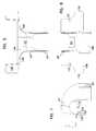
- FIG. 1shows a first perspective view of an exit trough assembly according to the present invention mounted to a lateral trough.
- FIG. 1 ais second perspective view of the exit trough assembly of FIG. 1 .
- FIG. 1 bis a perspective view of the exit trough assembly of FIG. 1 a showing the pivot plate in a closed position.
- FIG. 2shows a disassembled view of the exit trough assembly of FIG. 1 .
- FIG. 3is a side view of the exit trough assembly of FIG. 1 .
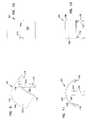
- FIG. 4is a perspective view of an exit trough according to the present invention with two flanges shown removed from the trough.
- FIG. 4 ais a perspective view of the exit trough of FIG. 4 showing both flanges attached to the exit trough.
- FIG. 5is a top view of the exit trough of FIG. 4 .
- FIG. 6is a front view of the exit trough of FIG. 4 .
- FIG. 7is a side view of the exit trough of FIG. 4 .
- FIG. 8is a perspective view of an exit trough according to the present invention and showing a removed modular insert piece.
- FIG. 9is a perspective view of the modular insert shown in FIG. 8 .
- FIG. 10is a top view of the modular insert of FIG. 9 .
- FIG. 11is a side view of the modular insert of FIG. 9 .
- FIG. 12is a front view of the modular insert of FIG. 9 .
- FIG. 13is a top view of the exit trough of FIG. 8 with the insert piece removed, thereby exposing an insert aperture.
- FIG. 14is a front view of the exit trough of FIG. 13 .
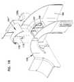
- FIG. 15is a perspective view of an exit trough according to the present invention and showing a removed modular insert piece with guidewall that curves in a first direction as it leads toward the downspout.
- FIG. 16is a top view of the exit trough of FIG. 15 with the modular insert piece placed within the exit trough according to the present invention.
- FIG. 17is a front view of the exit trough of FIG. 16 .
- FIG. 18is a perspective view of an exit trough according to the present invention and showing a removed modular insert piece with guidewall that curves in a second direction as it leads toward the downspout.
- FIG. 19is a top view of the exit trough of FIG. 18 with the modular insert piece placed within the exit trough according to the present invention.
- FIG. 20is a front view of the exit trough of FIG. 19 .
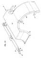
- FIG. 21is a disassembled perspective view of an exit cover according to the present invention.
- FIG. 22is a top view of a cover plate according to the present invention.
- FIG. 23is a front view of the cover plate of FIG. 22 .
- FIG. 24is a side view of the cover plate of FIG. 22 .
- FIG. 25is a side view of an exit cover according to the present invention showing the pivot plate in a closed position.
- FIG. 26is a side view of the exit cover of FIG. 25 showing the pivot plate in an open position.
- FIG. 27is a side view of a pivot plate according to the present invention.
- FIG. 28is a front view of the pivot plate of FIG. 27 .
- FIG. 29is a top view of the pivot plate of FIG. 27 .
- FIG. 30is a top view of an alternative embodiment of a pivot plate according to the present invention.
- FIG. 31is a top view of another alternative embodiment of a pivot plate according to the present invention.
- FIG. 32is a first perspective view of a removable flange according to the present invention.
- FIG. 33is a second perspective view of the flange of FIG. 32 .
- Lateral trough section 20defines a cable pathway 22 for routing optical fiber cables between locations.
- Lateral trough section 20 and exit trough 100can be part of a cable routing system typically within a structure, such as a building having optical fiber signal transmitting equipment.
- Lateral trough section 20typically is suspended from a ceiling structure by any suitable means (not shown).
- U.S. Pat. Nos. 5,067,678 and 5,316,243disclose various cable routing systems, including lateral trough sections like lateral trough section 20 illustrated in FIGS. 1-3.
- Exit trough 100is not only usable with lateral trough section 20 shown in FIGS. 1-3, but also with other cable routing systems disclosed in U.S. Pat. Nos. 5,067,678 and 5,316,243, the disclosures of which are hereby incorporated by reference, and other cable routing systems. Exit trough 100 is an improvement over the exit troughs shown and described in U.S. Pat. No. 5,937,131, the disclosure of which is hereby incorporated by reference.
- lateral trough section 20includes first and second upstanding sides 24 , 26 , and a bottom 28 extending therebetween and defining cable pathway 22 .
- Side 24includes a top edge 30 .
- Opposite side 26also includes similar top edge 32 .
- Lateral trough section 20includes a plurality of attachment members 34 on an outside portion for use in attaching lateral trough sections 20 together end to end, or adding other system hardware.
- exit trough 100mounts to lateral trough section 20 adjacent to top edge 30 of side 24 .
- Exit trough 100creates a cable exit pathway from lateral trough section 20 .
- exit trough 100mounts to lateral trough section 20 through attachment member 34 , such as with a fastener.
- Exit trough 100includes a bracket portion 102 including an outer projecting member 104 , an inner projecting member 106 , and a connecting member 108 .
- Bracket portion 102generally defines a U-shape for receipt of a portion of side 24 such that top edge 30 is positioned adjacent to connecting member 108 .
- Exit trough 100conveniently and securely mounts to lateral trough section 20 via one or more fasteners positioned through outer projecting member 104 and engaged with attachment member 34 of lateral trough section 20 .
- the exit trough 100may also include a support arm 10 extending from the bottom side of the lateral trough section 20 to a point beneath the exit trough 100 .
- bracket portion 102For protection of the optical fiber cables, inner projecting member 106 of bracket portion 102 is tapered. As shown in FIG. 4, bracket portion 102 generally extends from a first end 116 to a second end 118 . A middle 120 is positioned between the first and second ends 116 , 118 . At first and second ends 116 , 118 , two cable lead-ins 124 , 134 are provided. First lead-in 124 includes an upper surface portion 126 having an upwardly curved shape. Second lead-in 134 at an opposite end of bracket portion 102 faces in an opposite direction to first lead-in 124 . Second lead-in 134 includes a similarly configured upwardly curved surface 136 .
- the two cable lead-ins 124 and 134each define a slot 119 and hole 121 for receiving snap-mounted removable flanges 123 and 125 .
- Flanges 123 and 125each include a downwardly depending surface 127 which, when flanges 123 and 125 are snap-mounted to the lead-ins 124 and 134 , define cable pathways between the flanges 123 and 125 and the inner projecting member 106 of the bracket portion 102 to assist with cable management.
- Flanges 123 and 125are optional, and provide a downwardly depending flange structure to assist with cable management and retention of the cable when desired.
- Flanges 123 and 125include posts or tabs 122 which are received by the slot 119 and hole 121 of the cable lead-ins for snap-mounting of the flanges 123 and 125 .
- the flanges 123 and 125may also include an alignment rail 122 ′ (see FIG. 33) to assist in mounting the flange to the exit trough 100 .
- Exit trough 100includes an exit trough portion 144 extending from bracket portion 102 at middle 120 away from lateral trough section 20 .
- Exit trough portion 144includes a bottom trough surface 146 and upstanding sides 148 on opposite sides of bottom trough surface 146 .
- Generally bottom trough surface 146extends upwardly and away from top edge 30 of lateral trough section 20 , and includes a convex shape.
- Upstanding sides 148extend from each respective lead-in 124 , 134 , and also define convex shapes.
- Exit trough portion 144defines a cable pathway linked to cable pathway 22 of lateral trough section 20 via cable pathways of the lead-ins 124 , 134 .
- exit trough portion 144links lateral trough section 20 to a downspout 160 .
- Downspout 160generally provides a cable pathway for cable exiting in a downward direction relative to lateral trough section 20 .
- the bottom trough surface 146may define an insert aperture 151 .
- the insert apertureis configured to receive a removable modular insert piece 161 .
- the insert aperture 151may receive modular inserts each having different cable management components.
- an insert piece 161may simply be flat, having no cable management component.
- the insert piece(as seen in FIGS. 15-20) may have an upstanding guidewall 171 for arranging cables as they pass from the lateral trough to the exit trough.
- the guidewall 171may be curved so as to manage and protect the cable being guided.
- the guidewall 171helps keep the cables from bunching up, such as may occur as greater and greater numbers of cables exit the trough 20 .
- an insert piecemay be configured to have a guidewall 171 that curves from end 135 a toward downspout 160 (shown in FIGS. 15-17 as insert 161 ′), or alternatively from end 135 b (shown in FIGS. 18-20 as insert 161 ′′)
- the exit troughmay be assembled quickly and easily with the desired configuration. Further, the exit rough can be quickly and easily modified to meet changing needs.
- modular insert piece 161includes a curved major surface 163 having a first convex side 165 and a second concave side 167 .
- the major surface 163has edges 169 .
- the insert piece 161includes guide tabs 173 extending from two edges of the major surface 163 on the concave side 167 of the major surface.
- the guide tabs 173may each include a detent ridge 175 configured to engage a retaining wall 177 of the cable exit trough. Notches 174 mate with protrusions 152 on the cable exit trough.
- the modular insert piece 161may also include a plurality of alignment pins 179 protruding from the concave side 167 of the major surface 163 .
- the alignment pins 179are spaced to be received by alignment holes 181 in the cable exit trough seen in FIGS. 8, 13 , 15 and 18 .
- the guide tabs 173protrude below exit trough 100 , to provide structure to release insert piece 161 so the insert piece can be changed as desired.
- bottom trough surface 146may include an upstanding guidewall 171 dividing the cable pathway of the exit trough portion 144 for improving cable management.
- the guidewall 171preferably is curved to prevent damage to the cable.
- the guidewallmay be incorporated into an insert piece or may be formed directly on the bottom trough surface 146 .
- exit trough 100mounted to lateral trough section 20 , cable extending generally horizontally to the ground through lateral trough section 20 is allowed to route upwardly and away from lateral trough section 20 , and then to route downwardly through downspout 160 for connection to optical transmission equipment, or other uses.
- Downspout 160is connectable via any suitable means to other cable routing components, such as vertical troughs or conduit, as desired.
- the various curves provided with exit trough 100help protect the optical fiber cables from being bent beyond a minimum radius of curvature.
- the disclosed exit trough 100allows for exit pathways from the lateral trough section 20 without modification to the lateral trough section 20 . This is useful during initial system setup, and also during modifications of the system at later dates. Exit trough 100 can be added at any time quickly and easily. Cable damage is avoided since any cables in lateral trough section 20 are not disturbed and do not have to be moved when exit troughs 100 are added. Also, fasteners are all that is needed to mount the preferred bracket portion 102 of the exit trough 100 to the lateral trough section 20 . In addition to the downspout 160 other directional components are possible from exit trough portions 144 of exit trough 100 such as horizontal portions which lead horizontally away from the lateral trough instead of vertically.
- the preferred embodiments of exit trough 100also include an exit cover 31 .
- the cover 31prevents dust and other foreign material from falling into or collecting inside the exit trough and lateral trough while allowing easy access to the troughs.
- the exit cover 31includes a cover plate 33 .
- the cover plate 33is sized and shaped to cover the cable pathways of the lead-ins 124 and 134 as well as the cable pathway of the exit trough portion 144 and the lateral trough 20 .
- the cover plate 33is configured with hinge posts 35 .
- the cover 31includes a pivoting door or pivot plate 37 .
- the pivot plate 37defines hinge tabs 39 for rotatably receiving the hinge posts 35 of the cover plate 33 .
- the cover plate 33may be configured with the hinge tabs 39 and the pivot plate 37 may be configured with the hinge posts 35 to be received by the hinge tabs 39 of the cover plate 33 .
- the hinge posts 35 and hinge tabs 39define a hinge axis which is parallel to the lateral trough section 20 .
- the cover plate 33includes retention tabs or clips 41 which in combination with detent grooves 43 or clips 43 ′ (see FIGS. 3-8) in the exit trough secure the exit cover 31 to the exit trough 100 .
- the cover plate 33includes downward outer lips 49
- the pivot plateincludes a downward outer lip 51 to surround and protect lateral trough section 20 and exit trough 100 .
- the cover plate 33is roughly t-shaped with the post of the “T” curving downward to cover the downspout 160 .
- Cover plate 33includes sidewalls 33 ′ to cover the lead-ins of the exit trough 100 .
- the pivot plate 37may be made in varying sizes for covering larger or smaller lateral troughs.
- the pivot plate 37may be pivoted relative to the cover plate 33 between an open position as shown in FIG. 26 and a closed position as shown in FIG. 25 .
- an access portis created between the upstanding side 26 of the lateral trough section and the cover plate 33 , thereby allowing insertion or removal of cables from the trough.
- cablesmay be inserted or removed to or from the lateral trough without the cumbersome step of completely removing the entire cover 31 from the exit trough 100 . This often occurs when a new downspout and exit trough is added for new cables.
- the upstream exit troughscan each be covered with a cover 31 . Only the pivot plates 37 of the covers 31 need to be moved to drop in new cables.
Landscapes
- Engineering & Computer Science (AREA)
- Architecture (AREA)
- Civil Engineering (AREA)
- Structural Engineering (AREA)
- Physics & Mathematics (AREA)
- Optics & Photonics (AREA)
- General Physics & Mathematics (AREA)
- Laying Of Electric Cables Or Lines Outside (AREA)
- Details Of Indoor Wiring (AREA)
- Electric Cable Installation (AREA)
- Near-Field Transmission Systems (AREA)
- Coupling Device And Connection With Printed Circuit (AREA)
- Waveguide Aerials (AREA)
- Light Guides In General And Applications Therefor (AREA)
- Multi-Conductor Connections (AREA)
Abstract
Description
Claims (18)
Priority Applications (16)
| Application Number | Priority Date | Filing Date | Title |
|---|---|---|---|
| US09/680,700US6625373B1 (en) | 2000-10-06 | 2000-10-06 | Cable exit trough with insert |
| AT01977447TATE358828T1 (en) | 2000-10-06 | 2001-10-04 | CABLE EXIT CHANNEL WITH INSERT |
| ES01977447TES2282302T3 (en) | 2000-10-06 | 2001-10-04 | CHANNEL OUTPUT CHANNEL WITH INSERTS. |
| AU2001296565AAU2001296565A1 (en) | 2000-10-06 | 2001-10-04 | Cable exit trough with insert |
| DE60127719TDE60127719T2 (en) | 2000-10-06 | 2001-10-04 | Cable outlet channel with insert |
| EP01977447AEP1356321B1 (en) | 2000-10-06 | 2001-10-04 | Cable exit trough with insert |
| EP07001901.3AEP1795931B1 (en) | 2000-10-06 | 2001-10-04 | Cable exit trough with insert |
| HK04100834.6AHK1058068B (en) | 2000-10-06 | 2001-10-04 | Cable exit trough with insert |
| PCT/US2001/031022WO2002031549A2 (en) | 2000-10-06 | 2001-10-04 | Cable exit trough with insert |
| US10/622,501US6763169B2 (en) | 2000-10-06 | 2003-07-18 | Cable exit trough with insert |
| US10/890,417US6915056B2 (en) | 2000-10-06 | 2004-07-12 | Cable exit trough with insert |
| US12/456,693US7885503B2 (en) | 2000-10-06 | 2009-06-18 | Cable exit trough with insert |
| US12/930,729US8041174B2 (en) | 2000-10-06 | 2011-01-13 | Cable exit trough with insert |
| US13/274,112US8306381B2 (en) | 2000-10-06 | 2011-10-14 | Cable exit trough with insert |
| US13/659,407US8712205B2 (en) | 2000-10-06 | 2012-10-24 | Cable exit trough with insert |
| US14/262,899US9470866B2 (en) | 2000-10-06 | 2014-04-28 | Cable exit trough with insert |
Applications Claiming Priority (1)
| Application Number | Priority Date | Filing Date | Title |
|---|---|---|---|
| US09/680,700US6625373B1 (en) | 2000-10-06 | 2000-10-06 | Cable exit trough with insert |
Related Child Applications (1)
| Application Number | Title | Priority Date | Filing Date |
|---|---|---|---|
| US10/622,501ContinuationUS6763169B2 (en) | 2000-10-06 | 2003-07-18 | Cable exit trough with insert |
Publications (1)
| Publication Number | Publication Date |
|---|---|
| US6625373B1true US6625373B1 (en) | 2003-09-23 |
Family
ID=24732149
Family Applications (3)
| Application Number | Title | Priority Date | Filing Date |
|---|---|---|---|
| US09/680,700Expired - LifetimeUS6625373B1 (en) | 2000-10-06 | 2000-10-06 | Cable exit trough with insert |
| US10/622,501Expired - LifetimeUS6763169B2 (en) | 2000-10-06 | 2003-07-18 | Cable exit trough with insert |
| US10/890,417Expired - LifetimeUS6915056B2 (en) | 2000-10-06 | 2004-07-12 | Cable exit trough with insert |
Family Applications After (2)
| Application Number | Title | Priority Date | Filing Date |
|---|---|---|---|
| US10/622,501Expired - LifetimeUS6763169B2 (en) | 2000-10-06 | 2003-07-18 | Cable exit trough with insert |
| US10/890,417Expired - LifetimeUS6915056B2 (en) | 2000-10-06 | 2004-07-12 | Cable exit trough with insert |
Country Status (7)
| Country | Link |
|---|---|
| US (3) | US6625373B1 (en) |
| EP (2) | EP1795931B1 (en) |
| AT (1) | ATE358828T1 (en) |
| AU (1) | AU2001296565A1 (en) |
| DE (1) | DE60127719T2 (en) |
| ES (1) | ES2282302T3 (en) |
| WO (1) | WO2002031549A2 (en) |
Cited By (30)
| Publication number | Priority date | Publication date | Assignee | Title |
|---|---|---|---|---|
| US20040001685A1 (en)* | 2002-06-27 | 2004-01-01 | Daoud Bassel H. | Optical fiber closure having an integrated bend limiting feature |
| US20040017993A1 (en)* | 2000-10-06 | 2004-01-29 | Adc Telecommunications, Inc. | Cable exit trough with insert |
| US20040124321A1 (en)* | 2000-09-26 | 2004-07-01 | Adc Telecommunications Inc. | Cable trough method with separate side elements |
| US20040175088A1 (en)* | 2003-03-05 | 2004-09-09 | Dagley Mark R. | High density fiber optic distribution frame |
| US20040175089A1 (en)* | 2003-03-05 | 2004-09-09 | Dagley Mark R. | High density fiber optic distribution frame |
| US6951986B1 (en) | 2004-12-29 | 2005-10-04 | Sbc Knowledge Ventures, L.P. | Adjustable routing device for routing fiber optic jumpers from fiber optic jumper raceways |
| US20050253124A1 (en)* | 2004-05-13 | 2005-11-17 | Thomas & Betts International, Inc. | Insert for aiding in wire pulling through conduit bodies |
| US20060013552A1 (en)* | 2000-10-06 | 2006-01-19 | Adc Telecommunications, Inc. | Cable exit trough with insert |
| US20060269210A1 (en)* | 2005-05-31 | 2006-11-30 | Panduit Corp. | Parallel path cable routing system |
| US20070092196A1 (en)* | 2005-10-07 | 2007-04-26 | Yilmaz Bayazit | Cable trough system and method |
| US20080181568A1 (en)* | 2007-01-26 | 2008-07-31 | Derek Sayres | Cable trough system and method |
| USD576106S1 (en) | 2007-01-26 | 2008-09-02 | Adc Telecommunications, Inc. | Fiber trough lateral component |
| USD576109S1 (en) | 2007-01-26 | 2008-09-02 | Adc Telecommunications, Inc. | Fiber trough base |
| USD576107S1 (en) | 2007-01-26 | 2008-09-02 | Adc Telecommunications, Inc. | Fiber trough lateral component |
| USD576108S1 (en) | 2007-01-26 | 2008-09-02 | Adc Telecommunications, Inc. | Fiber trough horizontal T component |
| USD576559S1 (en) | 2007-01-26 | 2008-09-09 | Adc Telecommunications, Inc. | Fiber trough horizontal T component |
| USD576560S1 (en) | 2007-01-26 | 2008-09-09 | Adc Telecommunications, Inc. | Fiber trough horizontal T component |
| USD576956S1 (en) | 2007-01-26 | 2008-09-16 | Adc Telecommunications, Inc. | Fiber trough base |
| USD577684S1 (en) | 2007-01-26 | 2008-09-30 | Adc Telecommunications, Inc. | Fiber trough snaps |
| US20090108145A1 (en)* | 2007-10-26 | 2009-04-30 | Panduit Corp. | Cable Pathway System |
| US7659560B2 (en) | 2005-09-01 | 2010-02-09 | Micron Technology, Inc. | Transistor structures |
| US20100307080A1 (en)* | 2009-06-05 | 2010-12-09 | David Parshad | Office partition system |
| US7860365B2 (en) | 2007-11-16 | 2010-12-28 | Adc Telecommunications, Inc. | Edge protector for fiber optic cable routing |
| US20120279745A1 (en)* | 2011-05-05 | 2012-11-08 | Stefan Badura | Cable strain relief device for cable closures and cable closure having at least one such cable strain relief device |
| USD703151S1 (en)* | 2011-02-04 | 2014-04-22 | D-Line (Europe) Limited | Cable conduit |
| US20190331260A1 (en)* | 2018-04-25 | 2019-10-31 | Telect, Inc. | Cable Trough System |
| USD887992S1 (en) | 2018-04-25 | 2020-06-23 | Telect, Inc. | Cable trough attachment assembly |
| US20210167469A1 (en)* | 2019-11-29 | 2021-06-03 | Yazaki Corporation | Bus Bar Module |
| USD938922S1 (en)* | 2019-07-31 | 2021-12-21 | Basor Electric, Inc. | Cable drop component |
| US12072546B2 (en)* | 2019-07-19 | 2024-08-27 | Commscope Technologies Llc | Cable trough and method |
Families Citing this family (11)
| Publication number | Priority date | Publication date | Assignee | Title |
|---|---|---|---|---|
| US6448495B1 (en)* | 2001-01-12 | 2002-09-10 | Fiber Management Solutions, Inc. | Fiber optic cable raceway outlet with raceway cover, and method |
| US20020094184A1 (en)* | 2001-01-12 | 2002-07-18 | Michael Mattei | Fiber optic cable raceway outlet and method |
| GB0214882D0 (en)* | 2002-06-27 | 2002-08-07 | Tyco Electronics Raychem Nv | Optical fibre exit conduit |
| US7806387B2 (en)* | 2007-07-11 | 2010-10-05 | Ctb, Inc. | Cable guide |
| US7848608B2 (en)* | 2008-02-05 | 2010-12-07 | Adc Telecommunications, Inc. | Fiber routing system with drop-in device |
| FR2979492B1 (en)* | 2011-08-30 | 2013-09-27 | Airbus Operations Sas | ASSEMBLY COMPRISING A GUIDE FOR CABLES AND A DEVICE FOR DERIVATION, AND ASSOCIATED DERIVATION DEVICE |
| DE102013213131A1 (en)* | 2013-07-04 | 2015-01-08 | Airbus Operations Gmbh | Arrangement for cable routing, mounting method, cable duct and holding body |
| US9466959B2 (en) | 2014-01-24 | 2016-10-11 | Ortronics, Inc. | Pathway cable guide |
| EP3867982A4 (en) | 2018-10-19 | 2022-07-13 | CommScope Technologies LLC | TELECOMMUNICATIONS TERMINAL WITH BREAK CORD |
| DE102019121480B4 (en) | 2019-08-08 | 2024-03-07 | Langmatz Gmbh | Connecting bridge and system for guiding optical fibers |
| CN112027350B (en)* | 2020-08-19 | 2022-06-21 | 南京中车浦镇城轨车辆有限责任公司 | Reassembling type magic hole wire casing ribbon guiding device |
Citations (18)
| Publication number | Priority date | Publication date | Assignee | Title |
|---|---|---|---|---|
| US5067678A (en) | 1989-07-31 | 1991-11-26 | Adc Telecommunications, Inc. | Optic cable management system |
| US5160811A (en) | 1990-04-27 | 1992-11-03 | Tyton Corporation | Duct transition converter and flexible connectors including same |
| US5161580A (en) | 1990-08-27 | 1992-11-10 | Tyton Corporation | Cable duct fitting with removable cover |
| US5240209A (en) | 1992-11-17 | 1993-08-31 | Telect, Inc. | Telecommunication multiple cable carrier |
| US5271585A (en) | 1990-10-01 | 1993-12-21 | Zetena Jr Maurice F | Modular fiber optics raceway permitting flexible installation |
| US5316243A (en) | 1989-07-31 | 1994-05-31 | Adc Telecommunications, Inc. | Optic cable management |
| US5335349A (en) | 1992-12-14 | 1994-08-02 | Telect, Inc. | Telecommunication overhead cable distribution assembly |
| US5394502A (en)* | 1993-12-21 | 1995-02-28 | United Technologies Corporation | Fiber optic cable harness break-out fitting |
| US5503354A (en) | 1994-01-04 | 1996-04-02 | Telect, Inc. | Telecommunication overhead cable distribution universal support bracket |
| US5683211A (en) | 1993-08-03 | 1997-11-04 | Bell Atlantic Network Services, Inc. | Fiber optic saddle |
| US5752781A (en) | 1997-03-14 | 1998-05-19 | Adc Telecommunications, Inc. | Fiber trough coupling |
| US5917982A (en)* | 1998-01-05 | 1999-06-29 | The Wiremold Company | Fiber optic cable capable metal raceway system |
| US5923753A (en) | 1997-11-17 | 1999-07-13 | Adc Telecommunications, Inc. | Optic cable exit trough with bypass |
| US5937131A (en) | 1997-11-17 | 1999-08-10 | Adc Telecommunications, Inc. | Optical cable exit trough |
| US5995699A (en) | 1998-01-05 | 1999-11-30 | The Wiremold Company | Fiber optic cable raceway system cross reference to related applications |
| US6037538A (en) | 1997-04-28 | 2000-03-14 | Brooks; Gary Douglas | Cable raceway |
| US6076779A (en) | 1999-08-04 | 2000-06-20 | Adc Telecommunications, Inc. | Cable guiding trough |
| US6415091B1 (en)* | 1998-12-04 | 2002-07-02 | Schroff Gmbh | Guide and support element |
Family Cites Families (5)
| Publication number | Priority date | Publication date | Assignee | Title |
|---|---|---|---|---|
| US6002089A (en)* | 1997-09-26 | 1999-12-14 | The Wiremold Company | Non-linear raceway section having radial insert |
| US6535683B1 (en)* | 2000-10-06 | 2003-03-18 | Adc Telecommunications, Inc. | Cable exit trough with cover |
| US6625373B1 (en) | 2000-10-06 | 2003-09-23 | Adc Telecommunications, Inc. | Cable exit trough with insert |
| US6546179B2 (en)* | 2001-01-25 | 2003-04-08 | Hector D. Petri | Guide for routing cables through panel openings |
| US6708918B2 (en)* | 2001-03-01 | 2004-03-23 | Adc Telecommunications, Inc. | Cable guiding fins |
- 2000
- 2000-10-06USUS09/680,700patent/US6625373B1/ennot_activeExpired - Lifetime
- 2001
- 2001-10-04ATAT01977447Tpatent/ATE358828T1/enactive
- 2001-10-04AUAU2001296565Apatent/AU2001296565A1/ennot_activeAbandoned
- 2001-10-04ESES01977447Tpatent/ES2282302T3/ennot_activeExpired - Lifetime
- 2001-10-04WOPCT/US2001/031022patent/WO2002031549A2/enactiveIP Right Grant
- 2001-10-04EPEP07001901.3Apatent/EP1795931B1/ennot_activeExpired - Lifetime
- 2001-10-04EPEP01977447Apatent/EP1356321B1/ennot_activeExpired - Lifetime
- 2001-10-04DEDE60127719Tpatent/DE60127719T2/ennot_activeExpired - Lifetime
- 2003
- 2003-07-18USUS10/622,501patent/US6763169B2/ennot_activeExpired - Lifetime
- 2004
- 2004-07-12USUS10/890,417patent/US6915056B2/ennot_activeExpired - Lifetime
Patent Citations (19)
| Publication number | Priority date | Publication date | Assignee | Title |
|---|---|---|---|---|
| US5316243A (en) | 1989-07-31 | 1994-05-31 | Adc Telecommunications, Inc. | Optic cable management |
| US5067678A (en) | 1989-07-31 | 1991-11-26 | Adc Telecommunications, Inc. | Optic cable management system |
| US5160811A (en) | 1990-04-27 | 1992-11-03 | Tyton Corporation | Duct transition converter and flexible connectors including same |
| US5161580A (en) | 1990-08-27 | 1992-11-10 | Tyton Corporation | Cable duct fitting with removable cover |
| US5271585A (en) | 1990-10-01 | 1993-12-21 | Zetena Jr Maurice F | Modular fiber optics raceway permitting flexible installation |
| US5316244A (en) | 1990-10-01 | 1994-05-31 | Zetena Jr Maurice F | Supporting brackets for cable raceways |
| US5240209A (en) | 1992-11-17 | 1993-08-31 | Telect, Inc. | Telecommunication multiple cable carrier |
| US5335349A (en) | 1992-12-14 | 1994-08-02 | Telect, Inc. | Telecommunication overhead cable distribution assembly |
| US5683211A (en) | 1993-08-03 | 1997-11-04 | Bell Atlantic Network Services, Inc. | Fiber optic saddle |
| US5394502A (en)* | 1993-12-21 | 1995-02-28 | United Technologies Corporation | Fiber optic cable harness break-out fitting |
| US5503354A (en) | 1994-01-04 | 1996-04-02 | Telect, Inc. | Telecommunication overhead cable distribution universal support bracket |
| US5752781A (en) | 1997-03-14 | 1998-05-19 | Adc Telecommunications, Inc. | Fiber trough coupling |
| US6037538A (en) | 1997-04-28 | 2000-03-14 | Brooks; Gary Douglas | Cable raceway |
| US5923753A (en) | 1997-11-17 | 1999-07-13 | Adc Telecommunications, Inc. | Optic cable exit trough with bypass |
| US5937131A (en) | 1997-11-17 | 1999-08-10 | Adc Telecommunications, Inc. | Optical cable exit trough |
| US5917982A (en)* | 1998-01-05 | 1999-06-29 | The Wiremold Company | Fiber optic cable capable metal raceway system |
| US5995699A (en) | 1998-01-05 | 1999-11-30 | The Wiremold Company | Fiber optic cable raceway system cross reference to related applications |
| US6415091B1 (en)* | 1998-12-04 | 2002-07-02 | Schroff Gmbh | Guide and support element |
| US6076779A (en) | 1999-08-04 | 2000-06-20 | Adc Telecommunications, Inc. | Cable guiding trough |
Non-Patent Citations (9)
| Title |
|---|
| ADC Telecommunications brochure entitled " FiberGuide(R) Fiber Management Systems," 37 pages, dated Jun. 1998. |
| ADC Telecommunications brochure entitled "ADC FiberGuide(R) System Express Exit(TM) 2x2," 2 pages, dated May 1999. |
| ADC Telecommunications brochure entitled "Fiber Guide(TM) Fiber Management System," 6 pages, dated Jun., 1989. |
| ADC Telecommunications brochure entitled "FiberGuide(R) Fiber Management Systems," 33 pages, dated Oct., 1995. |
| ADC Telecommunications brochure entitled " FiberGuide® Fiber Management Systems," 37 pages, dated Jun. 1998. |
| ADC Telecommunications brochure entitled "ADC FiberGuide® System Express Exit™ 2x2," 2 pages, dated May 1999. |
| ADC Telecommunications brochure entitled "Fiber Guide™ Fiber Management System," 6 pages, dated Jun., 1989. |
| ADC Telecommunications brochure entitled "FiberGuide® Fiber Management Systems," 33 pages, dated Oct., 1995. |
| Warren & Brown & Staff brochure pages entitled "lightpaths," Issue 2, 11 pages, dated 1995. |
Cited By (72)
| Publication number | Priority date | Publication date | Assignee | Title |
|---|---|---|---|---|
| US20040124321A1 (en)* | 2000-09-26 | 2004-07-01 | Adc Telecommunications Inc. | Cable trough method with separate side elements |
| US8950051B2 (en) | 2000-09-26 | 2015-02-10 | Adc Telecommunications, Inc. | Cable trough method with separate side elements |
| US7155104B2 (en) | 2000-10-06 | 2006-12-26 | Adc Telecommunications, Inc. | Cable exit trough with insert |
| US8306381B2 (en) | 2000-10-06 | 2012-11-06 | Adc Telecommunications, Inc. | Cable exit trough with insert |
| US9470866B2 (en) | 2000-10-06 | 2016-10-18 | Commscope Technologies Llc | Cable exit trough with insert |
| US8712205B2 (en) | 2000-10-06 | 2014-04-29 | Adc Telecommunications, Inc. | Cable exit trough with insert |
| US20070230888A1 (en)* | 2000-10-06 | 2007-10-04 | Adc Telecommunications, Inc. | Cable exit trough with insert |
| US6763169B2 (en)* | 2000-10-06 | 2004-07-13 | Adc Telecommunications, Inc. | Cable exit trough with insert |
| US20040017993A1 (en)* | 2000-10-06 | 2004-01-29 | Adc Telecommunications, Inc. | Cable exit trough with insert |
| US20110116754A1 (en)* | 2000-10-06 | 2011-05-19 | Adc Telecommunicatios, Inc. | Cable exit trough with insert |
| US6915056B2 (en) | 2000-10-06 | 2005-07-05 | Adc Telecommunications, Inc. | Cable exit trough with insert |
| US20100002998A1 (en)* | 2000-10-06 | 2010-01-07 | Adc Telecommunications, Inc. | Cable exit trough with insert |
| US7551827B2 (en) | 2000-10-06 | 2009-06-23 | Adc Telecommunications, Inc. | Cable exit trough with insert |
| US20060013552A1 (en)* | 2000-10-06 | 2006-01-19 | Adc Telecommunications, Inc. | Cable exit trough with insert |
| US8041174B2 (en) | 2000-10-06 | 2011-10-18 | Adc Telecommunications, Inc. | Cable exit trough with insert |
| US7885503B2 (en) | 2000-10-06 | 2011-02-08 | Adc Telecommunications, Inc. | Cable exit trough with insert |
| US6868218B2 (en)* | 2002-06-27 | 2005-03-15 | Lucent Technologies Inc. | Optical fiber closure having an integrated bend limiting feature |
| US20040001685A1 (en)* | 2002-06-27 | 2004-01-01 | Daoud Bassel H. | Optical fiber closure having an integrated bend limiting feature |
| US7006748B2 (en) | 2003-03-05 | 2006-02-28 | Corning Cable Systems Llc | High density fiber optic distribution frame |
| US20050058421A1 (en)* | 2003-03-05 | 2005-03-17 | Dagley Mark R. | High density fiber optic distribution frame |
| US6853795B2 (en) | 2003-03-05 | 2005-02-08 | Corning Cable Systems Llc | High density fiber optic distribution frame |
| US6819856B2 (en) | 2003-03-05 | 2004-11-16 | Corning Cable Systems Llc | High density fiber optic distribution frame |
| US20040175089A1 (en)* | 2003-03-05 | 2004-09-09 | Dagley Mark R. | High density fiber optic distribution frame |
| US20040175088A1 (en)* | 2003-03-05 | 2004-09-09 | Dagley Mark R. | High density fiber optic distribution frame |
| US20050253124A1 (en)* | 2004-05-13 | 2005-11-17 | Thomas & Betts International, Inc. | Insert for aiding in wire pulling through conduit bodies |
| US7484711B2 (en)* | 2004-05-13 | 2009-02-03 | Thomas & Betts International, Inc. | Insert for aiding in wire pulling through conduit bodies |
| US7102084B2 (en) | 2004-12-29 | 2006-09-05 | Sbc Knowledge Ventures, L.P. | Adjustable routing device and method for routing fiber optic jumpers from fiber optic jumper raceways |
| US20060137900A1 (en)* | 2004-12-29 | 2006-06-29 | Sbc Knowledge Ventures, L.P. | Adjustable routing device and method for routing fiber optic jumpers from fiber optic jumper raceways |
| US6951986B1 (en) | 2004-12-29 | 2005-10-04 | Sbc Knowledge Ventures, L.P. | Adjustable routing device for routing fiber optic jumpers from fiber optic jumper raceways |
| US7049525B1 (en) | 2004-12-29 | 2006-05-23 | Sbc Knowledge Ventures, L.P. | Adjustable routing device for routing jumpers from jumper raceways |
| US20060169483A1 (en)* | 2004-12-29 | 2006-08-03 | Sbc Knowledge Ventures, L.P. | Device for routing jumpers from a raceway |
| US7693386B2 (en) | 2005-05-31 | 2010-04-06 | Panduit Corp. | Parallel path cable routing system |
| US20060269210A1 (en)* | 2005-05-31 | 2006-11-30 | Panduit Corp. | Parallel path cable routing system |
| US7659560B2 (en) | 2005-09-01 | 2010-02-09 | Micron Technology, Inc. | Transistor structures |
| US20070092196A1 (en)* | 2005-10-07 | 2007-04-26 | Yilmaz Bayazit | Cable trough system and method |
| US20100142911A1 (en)* | 2005-10-07 | 2010-06-10 | Adc Telecommunications, Inc. | Cable Trough System and Method |
| US8965167B2 (en) | 2005-10-07 | 2015-02-24 | Adc Telecommunications, Inc. | Cable trough system and method |
| US9356436B2 (en) | 2005-10-07 | 2016-05-31 | Commscope Technologies Llc | Cable trough system and method |
| US7471868B2 (en) | 2005-10-07 | 2008-12-30 | Adc Telecommunications, Inc. | Cable trough system and method |
| US7668433B2 (en) | 2005-10-07 | 2010-02-23 | Adc Telecommunications, Inc. | Cable trough system and method |
| US20090158578A1 (en)* | 2005-10-07 | 2009-06-25 | Adc Telecommunications, Inc. | Cable Trough System and Method |
| USD609192S1 (en) | 2005-10-07 | 2010-02-02 | Adc Telecommunications, Inc. | Fiber trough horizontal cross component |
| US8254744B2 (en) | 2007-01-26 | 2012-08-28 | Adc Telecommunications, Inc. | Cable trough system and method |
| USD576560S1 (en) | 2007-01-26 | 2008-09-09 | Adc Telecommunications, Inc. | Fiber trough horizontal T component |
| US20080181568A1 (en)* | 2007-01-26 | 2008-07-31 | Derek Sayres | Cable trough system and method |
| US7742675B2 (en) | 2007-01-26 | 2010-06-22 | Adc Telecommunications, Inc. | Cable trough system and method |
| USD576106S1 (en) | 2007-01-26 | 2008-09-02 | Adc Telecommunications, Inc. | Fiber trough lateral component |
| US20100215332A1 (en)* | 2007-01-26 | 2010-08-26 | Adc Telecommuncations, Inc. | Cable Trough System and Method |
| USD576109S1 (en) | 2007-01-26 | 2008-09-02 | Adc Telecommunications, Inc. | Fiber trough base |
| USD576107S1 (en) | 2007-01-26 | 2008-09-02 | Adc Telecommunications, Inc. | Fiber trough lateral component |
| USD576108S1 (en) | 2007-01-26 | 2008-09-02 | Adc Telecommunications, Inc. | Fiber trough horizontal T component |
| USD577684S1 (en) | 2007-01-26 | 2008-09-30 | Adc Telecommunications, Inc. | Fiber trough snaps |
| USD576559S1 (en) | 2007-01-26 | 2008-09-09 | Adc Telecommunications, Inc. | Fiber trough horizontal T component |
| USD576956S1 (en) | 2007-01-26 | 2008-09-16 | Adc Telecommunications, Inc. | Fiber trough base |
| US20090108145A1 (en)* | 2007-10-26 | 2009-04-30 | Panduit Corp. | Cable Pathway System |
| US20090107696A1 (en)* | 2007-10-26 | 2009-04-30 | Panduit Corp. | Cable Pathway System |
| US7763800B2 (en) | 2007-10-26 | 2010-07-27 | Panduit Corp. | Cable pathway system |
| US20090107718A1 (en)* | 2007-10-26 | 2009-04-30 | Panduit Corp. | Cable Pathway System |
| US8047474B2 (en)* | 2007-10-26 | 2011-11-01 | Panduit Corp. | Cable pathway system |
| US7860365B2 (en) | 2007-11-16 | 2010-12-28 | Adc Telecommunications, Inc. | Edge protector for fiber optic cable routing |
| US20100307080A1 (en)* | 2009-06-05 | 2010-12-09 | David Parshad | Office partition system |
| US7975445B2 (en) | 2009-06-05 | 2011-07-12 | Inscape Corporation | Office partition system |
| USD756307S1 (en) | 2011-02-04 | 2016-05-17 | D-Line (Europe) Limited | Cable conduit |
| USD703151S1 (en)* | 2011-02-04 | 2014-04-22 | D-Line (Europe) Limited | Cable conduit |
| US8772641B2 (en)* | 2011-05-05 | 2014-07-08 | Ccs Technology, Inc. | Cable strain relief device for cable closures and cable closure having at least one such cable strain relief device |
| US20120279745A1 (en)* | 2011-05-05 | 2012-11-08 | Stefan Badura | Cable strain relief device for cable closures and cable closure having at least one such cable strain relief device |
| US20190331260A1 (en)* | 2018-04-25 | 2019-10-31 | Telect, Inc. | Cable Trough System |
| USD887992S1 (en) | 2018-04-25 | 2020-06-23 | Telect, Inc. | Cable trough attachment assembly |
| US12072546B2 (en)* | 2019-07-19 | 2024-08-27 | Commscope Technologies Llc | Cable trough and method |
| USD938922S1 (en)* | 2019-07-31 | 2021-12-21 | Basor Electric, Inc. | Cable drop component |
| US20210167469A1 (en)* | 2019-11-29 | 2021-06-03 | Yazaki Corporation | Bus Bar Module |
| US12142791B2 (en)* | 2019-11-29 | 2024-11-12 | Yazaki Corporation | Bus bar module |
Also Published As
| Publication number | Publication date |
|---|---|
| EP1356321A2 (en) | 2003-10-29 |
| ATE358828T1 (en) | 2007-04-15 |
| AU2001296565A1 (en) | 2002-04-22 |
| US20040017993A1 (en) | 2004-01-29 |
| US6915056B2 (en) | 2005-07-05 |
| DE60127719D1 (en) | 2007-05-16 |
| HK1058068A1 (en) | 2004-04-30 |
| DE60127719T2 (en) | 2007-12-27 |
| EP1356321B1 (en) | 2007-04-04 |
| US20040258386A1 (en) | 2004-12-23 |
| EP1795931A2 (en) | 2007-06-13 |
| WO2002031549A2 (en) | 2002-04-18 |
| US6763169B2 (en) | 2004-07-13 |
| ES2282302T3 (en) | 2007-10-16 |
| WO2002031549A3 (en) | 2003-09-04 |
| EP1795931A3 (en) | 2007-07-18 |
| EP1795931B1 (en) | 2018-05-23 |
Similar Documents
| Publication | Publication Date | Title |
|---|---|---|
| US6625373B1 (en) | Cable exit trough with insert | |
| US8041176B2 (en) | Cable exit trough with cover | |
| US9470866B2 (en) | Cable exit trough with insert | |
| US6597854B2 (en) | Optical cable exit trough | |
| HK1058068B (en) | Cable exit trough with insert | |
| HK1103132A (en) | Cable exit trough with insert |
Legal Events
| Date | Code | Title | Description |
|---|---|---|---|
| AS | Assignment | Owner name:ADC TELECOMMUNICATIONS, INC., MINNESOTA Free format text:ASSIGNMENT OF ASSIGNORS INTEREST;ASSIGNORS:WENTWORTH, MICHAEL J.;JOHNSON, BRIAN L.;JOHNSON, WAYNE;AND OTHERS;REEL/FRAME:011454/0502;SIGNING DATES FROM 20001030 TO 20001101 | |
| STCF | Information on status: patent grant | Free format text:PATENTED CASE | |
| FPAY | Fee payment | Year of fee payment:4 | |
| AS | Assignment | Owner name:JPMORGAN CHASE BANK, N.A., AS ADMINISTRATIVE AGENT Free format text:SECURITY AGREEMENT;ASSIGNOR:ADC TELECOMMUNICATIONS, INC.;REEL/FRAME:020753/0037 Effective date:20080403 | |
| AS | Assignment | Owner name:ADC TELECOMMUNICATIONS, INC., MINNESOTA Free format text:RELEASE BY SECURED PARTY;ASSIGNOR:JPMORGAN CHASE BANK, N.A.;REEL/FRAME:023758/0177 Effective date:20091124 | |
| FPAY | Fee payment | Year of fee payment:8 | |
| FPAY | Fee payment | Year of fee payment:12 | |
| AS | Assignment | Owner name:TYCO ELECTRONICS SERVICES GMBH, SWITZERLAND Free format text:ASSIGNMENT OF ASSIGNORS INTEREST;ASSIGNOR:ADC TELECOMMUNICATIONS, INC.;REEL/FRAME:036060/0174 Effective date:20110930 | |
| AS | Assignment | Owner name:COMMSCOPE EMEA LIMITED, IRELAND Free format text:ASSIGNMENT OF ASSIGNORS INTEREST;ASSIGNOR:TYCO ELECTRONICS SERVICES GMBH;REEL/FRAME:036956/0001 Effective date:20150828 | |
| AS | Assignment | Owner name:COMMSCOPE TECHNOLOGIES LLC, NORTH CAROLINA Free format text:ASSIGNMENT OF ASSIGNORS INTEREST;ASSIGNOR:COMMSCOPE EMEA LIMITED;REEL/FRAME:037012/0001 Effective date:20150828 | |
| AS | Assignment | Owner name:JPMORGAN CHASE BANK, N.A., AS COLLATERAL AGENT, ILLINOIS Free format text:PATENT SECURITY AGREEMENT (TERM);ASSIGNOR:COMMSCOPE TECHNOLOGIES LLC;REEL/FRAME:037513/0709 Effective date:20151220 Owner name:JPMORGAN CHASE BANK, N.A., AS COLLATERAL AGENT, ILLINOIS Free format text:PATENT SECURITY AGREEMENT (ABL);ASSIGNOR:COMMSCOPE TECHNOLOGIES LLC;REEL/FRAME:037514/0196 Effective date:20151220 Owner name:JPMORGAN CHASE BANK, N.A., AS COLLATERAL AGENT, IL Free format text:PATENT SECURITY AGREEMENT (TERM);ASSIGNOR:COMMSCOPE TECHNOLOGIES LLC;REEL/FRAME:037513/0709 Effective date:20151220 Owner name:JPMORGAN CHASE BANK, N.A., AS COLLATERAL AGENT, IL Free format text:PATENT SECURITY AGREEMENT (ABL);ASSIGNOR:COMMSCOPE TECHNOLOGIES LLC;REEL/FRAME:037514/0196 Effective date:20151220 | |
| AS | Assignment | Owner name:ANDREW LLC, NORTH CAROLINA Free format text:RELEASE BY SECURED PARTY;ASSIGNOR:JPMORGAN CHASE BANK, N.A.;REEL/FRAME:048840/0001 Effective date:20190404 Owner name:REDWOOD SYSTEMS, INC., NORTH CAROLINA Free format text:RELEASE BY SECURED PARTY;ASSIGNOR:JPMORGAN CHASE BANK, N.A.;REEL/FRAME:048840/0001 Effective date:20190404 Owner name:ALLEN TELECOM LLC, ILLINOIS Free format text:RELEASE BY SECURED PARTY;ASSIGNOR:JPMORGAN CHASE BANK, N.A.;REEL/FRAME:048840/0001 Effective date:20190404 Owner name:COMMSCOPE TECHNOLOGIES LLC, NORTH CAROLINA Free format text:RELEASE BY SECURED PARTY;ASSIGNOR:JPMORGAN CHASE BANK, N.A.;REEL/FRAME:048840/0001 Effective date:20190404 Owner name:COMMSCOPE, INC. OF NORTH CAROLINA, NORTH CAROLINA Free format text:RELEASE BY SECURED PARTY;ASSIGNOR:JPMORGAN CHASE BANK, N.A.;REEL/FRAME:048840/0001 Effective date:20190404 Owner name:COMMSCOPE TECHNOLOGIES LLC, NORTH CAROLINA Free format text:RELEASE BY SECURED PARTY;ASSIGNOR:JPMORGAN CHASE BANK, N.A.;REEL/FRAME:049260/0001 Effective date:20190404 Owner name:ALLEN TELECOM LLC, ILLINOIS Free format text:RELEASE BY SECURED PARTY;ASSIGNOR:JPMORGAN CHASE BANK, N.A.;REEL/FRAME:049260/0001 Effective date:20190404 Owner name:COMMSCOPE, INC. OF NORTH CAROLINA, NORTH CAROLINA Free format text:RELEASE BY SECURED PARTY;ASSIGNOR:JPMORGAN CHASE BANK, N.A.;REEL/FRAME:049260/0001 Effective date:20190404 Owner name:REDWOOD SYSTEMS, INC., NORTH CAROLINA Free format text:RELEASE BY SECURED PARTY;ASSIGNOR:JPMORGAN CHASE BANK, N.A.;REEL/FRAME:049260/0001 Effective date:20190404 Owner name:ANDREW LLC, NORTH CAROLINA Free format text:RELEASE BY SECURED PARTY;ASSIGNOR:JPMORGAN CHASE BANK, N.A.;REEL/FRAME:049260/0001 Effective date:20190404 | |
| AS | Assignment | Owner name:WILMINGTON TRUST, NATIONAL ASSOCIATION, AS COLLATE Free format text:PATENT SECURITY AGREEMENT;ASSIGNOR:COMMSCOPE TECHNOLOGIES LLC;REEL/FRAME:049892/0051 Effective date:20190404 Owner name:JPMORGAN CHASE BANK, N.A., NEW YORK Free format text:TERM LOAN SECURITY AGREEMENT;ASSIGNORS:COMMSCOPE, INC. OF NORTH CAROLINA;COMMSCOPE TECHNOLOGIES LLC;ARRIS ENTERPRISES LLC;AND OTHERS;REEL/FRAME:049905/0504 Effective date:20190404 Owner name:JPMORGAN CHASE BANK, N.A., NEW YORK Free format text:ABL SECURITY AGREEMENT;ASSIGNORS:COMMSCOPE, INC. OF NORTH CAROLINA;COMMSCOPE TECHNOLOGIES LLC;ARRIS ENTERPRISES LLC;AND OTHERS;REEL/FRAME:049892/0396 Effective date:20190404 Owner name:WILMINGTON TRUST, NATIONAL ASSOCIATION, AS COLLATERAL AGENT, CONNECTICUT Free format text:PATENT SECURITY AGREEMENT;ASSIGNOR:COMMSCOPE TECHNOLOGIES LLC;REEL/FRAME:049892/0051 Effective date:20190404 | |
| AS | Assignment | Owner name:RUCKUS WIRELESS, LLC (F/K/A RUCKUS WIRELESS, INC.), NORTH CAROLINA Free format text:RELEASE OF SECURITY INTEREST AT REEL/FRAME 049905/0504;ASSIGNOR:JPMORGAN CHASE BANK, N.A., AS COLLATERAL AGENT;REEL/FRAME:071477/0255 Effective date:20241217 Owner name:COMMSCOPE TECHNOLOGIES LLC, NORTH CAROLINA Free format text:RELEASE OF SECURITY INTEREST AT REEL/FRAME 049905/0504;ASSIGNOR:JPMORGAN CHASE BANK, N.A., AS COLLATERAL AGENT;REEL/FRAME:071477/0255 Effective date:20241217 Owner name:COMMSCOPE, INC. OF NORTH CAROLINA, NORTH CAROLINA Free format text:RELEASE OF SECURITY INTEREST AT REEL/FRAME 049905/0504;ASSIGNOR:JPMORGAN CHASE BANK, N.A., AS COLLATERAL AGENT;REEL/FRAME:071477/0255 Effective date:20241217 Owner name:ARRIS SOLUTIONS, INC., NORTH CAROLINA Free format text:RELEASE OF SECURITY INTEREST AT REEL/FRAME 049905/0504;ASSIGNOR:JPMORGAN CHASE BANK, N.A., AS COLLATERAL AGENT;REEL/FRAME:071477/0255 Effective date:20241217 Owner name:ARRIS TECHNOLOGY, INC., NORTH CAROLINA Free format text:RELEASE OF SECURITY INTEREST AT REEL/FRAME 049905/0504;ASSIGNOR:JPMORGAN CHASE BANK, N.A., AS COLLATERAL AGENT;REEL/FRAME:071477/0255 Effective date:20241217 Owner name:ARRIS ENTERPRISES LLC (F/K/A ARRIS ENTERPRISES, INC.), NORTH CAROLINA Free format text:RELEASE OF SECURITY INTEREST AT REEL/FRAME 049905/0504;ASSIGNOR:JPMORGAN CHASE BANK, N.A., AS COLLATERAL AGENT;REEL/FRAME:071477/0255 Effective date:20241217 |