US6625274B1 - Computer system and method for providing services to users of communication systems using service entities, interface entities, and a service bus - Google Patents
Computer system and method for providing services to users of communication systems using service entities, interface entities, and a service busDownload PDFInfo
- Publication number
- US6625274B1 US6625274B1US09/418,130US41813099AUS6625274B1US 6625274 B1US6625274 B1US 6625274B1US 41813099 AUS41813099 AUS 41813099AUS 6625274 B1US6625274 B1US 6625274B1
- Authority
- US
- United States
- Prior art keywords
- service
- entity
- interface
- entities
- bus
- Prior art date
- Legal status (The legal status is an assumption and is not a legal conclusion. Google has not performed a legal analysis and makes no representation as to the accuracy of the status listed.)
- Expired - Lifetime
Links
- 238000004891communicationMethods0.000titleclaimsabstractdescription44
- 238000000034methodMethods0.000titleclaimsdescription20
- 230000004044responseEffects0.000claimsdescription7
- 238000012986modificationMethods0.000claimsdescription5
- 230000004048modificationEffects0.000claimsdescription5
- 238000012544monitoring processMethods0.000claimsdescription3
- 230000008878couplingEffects0.000claims1
- 238000010168coupling processMethods0.000claims1
- 238000005859coupling reactionMethods0.000claims1
- 230000006870functionEffects0.000description34
- 238000007726management methodMethods0.000description11
- 238000010586diagramMethods0.000description8
- 238000013459approachMethods0.000description6
- 238000012937correctionMethods0.000description5
- 238000001514detection methodMethods0.000description5
- 230000003993interactionEffects0.000description4
- 230000002452interceptive effectEffects0.000description4
- 238000011161developmentMethods0.000description3
- 230000003116impacting effectEffects0.000description3
- 238000012545processingMethods0.000description3
- 230000009471actionEffects0.000description2
- 230000008859changeEffects0.000description2
- 230000000977initiatory effectEffects0.000description2
- 238000004519manufacturing processMethods0.000description2
- 230000006855networkingEffects0.000description2
- 230000008569processEffects0.000description2
- 230000011664signalingEffects0.000description2
- 235000006719Cassia obtusifoliaNutrition0.000description1
- 235000014552Cassia toraNutrition0.000description1
- 244000201986Cassia toraSpecies0.000description1
- 230000003416augmentationEffects0.000description1
- 238000006243chemical reactionMethods0.000description1
- 238000004590computer programMethods0.000description1
- 238000012423maintenanceMethods0.000description1
- 230000003287optical effectEffects0.000description1
- 238000012546transferMethods0.000description1
- 230000000007visual effectEffects0.000description1
Images


Classifications
- H—ELECTRICITY
- H04—ELECTRIC COMMUNICATION TECHNIQUE
- H04L—TRANSMISSION OF DIGITAL INFORMATION, e.g. TELEGRAPHIC COMMUNICATION
- H04L41/00—Arrangements for maintenance, administration or management of data switching networks, e.g. of packet switching networks
- H04L41/50—Network service management, e.g. ensuring proper service fulfilment according to agreements
- H04L41/5041—Network service management, e.g. ensuring proper service fulfilment according to agreements characterised by the time relationship between creation and deployment of a service
- H04L41/5051—Service on demand, e.g. definition and deployment of services in real time
- H—ELECTRICITY
- H04—ELECTRIC COMMUNICATION TECHNIQUE
- H04L—TRANSMISSION OF DIGITAL INFORMATION, e.g. TELEGRAPHIC COMMUNICATION
- H04L41/00—Arrangements for maintenance, administration or management of data switching networks, e.g. of packet switching networks
- H04L41/50—Network service management, e.g. ensuring proper service fulfilment according to agreements
- H04L41/5041—Network service management, e.g. ensuring proper service fulfilment according to agreements characterised by the time relationship between creation and deployment of a service
- H04L41/5048—Automatic or semi-automatic definitions, e.g. definition templates
- H—ELECTRICITY
- H04—ELECTRIC COMMUNICATION TECHNIQUE
- H04L—TRANSMISSION OF DIGITAL INFORMATION, e.g. TELEGRAPHIC COMMUNICATION
- H04L67/00—Network arrangements or protocols for supporting network services or applications
- H04L67/01—Protocols
- H04L67/10—Protocols in which an application is distributed across nodes in the network
- H—ELECTRICITY
- H04—ELECTRIC COMMUNICATION TECHNIQUE
- H04L—TRANSMISSION OF DIGITAL INFORMATION, e.g. TELEGRAPHIC COMMUNICATION
- H04L67/00—Network arrangements or protocols for supporting network services or applications
- H04L67/50—Network services
- H04L67/51—Discovery or management thereof, e.g. service location protocol [SLP] or web services
- H—ELECTRICITY
- H04—ELECTRIC COMMUNICATION TECHNIQUE
- H04L—TRANSMISSION OF DIGITAL INFORMATION, e.g. TELEGRAPHIC COMMUNICATION
- H04L9/00—Cryptographic mechanisms or cryptographic arrangements for secret or secure communications; Network security protocols
- H04L9/40—Network security protocols
- H—ELECTRICITY
- H04—ELECTRIC COMMUNICATION TECHNIQUE
- H04Q—SELECTING
- H04Q3/00—Selecting arrangements
- H04Q3/0016—Arrangements providing connection between exchanges
- H04Q3/0029—Provisions for intelligent networking
- H04Q3/0054—Service creation techniques
- H—ELECTRICITY
- H04—ELECTRIC COMMUNICATION TECHNIQUE
- H04L—TRANSMISSION OF DIGITAL INFORMATION, e.g. TELEGRAPHIC COMMUNICATION
- H04L69/00—Network arrangements, protocols or services independent of the application payload and not provided for in the other groups of this subclass
- H04L69/30—Definitions, standards or architectural aspects of layered protocol stacks
- H04L69/32—Architecture of open systems interconnection [OSI] 7-layer type protocol stacks, e.g. the interfaces between the data link level and the physical level
- H04L69/322—Intralayer communication protocols among peer entities or protocol data unit [PDU] definitions
- H04L69/329—Intralayer communication protocols among peer entities or protocol data unit [PDU] definitions in the application layer [OSI layer 7]
Definitions
- the inventionrelates to a system for providing services, and, more particularly, to a computer system for providing services to users of communication systems using service entities, interface entities, and a service bus.
- FIG. 14illustrates a system perspective for providing services using the prior art.
- a service provider 201provides services to a user 202 via a telephone system 203 .
- the service provider 201includes an operating system 204 , services 205 , and a network interface 206 .
- the services 205are implemented in software as stand-alone services. New services are provided by either adding new stand-alone services 205 to an existing service provider 201 or by adding an entirely new service provider. Examples of services for a telephone system implemented with the prior art approach include a call forwarding service and a call waiting service.
- each service provider 201may only communicate with a single telephone system 203 . Also, with the conventional approach, management of the services and network interfaces between service providers is disjoint, which causes an increase in management expenses.
- a new serviceis created by a service manufacturer in a closed and proprietary manner, and the augmentation of the deployed new service is difficult to perform and is restricted by the service manufacturer that created the service.
- the delivery of a new service created by a service manufactureris difficult to predict because the service manufacturer operates on its own independent delivery schedule.
- the new servicewhen deploying a new service with the conventional approach, the new service is often introduced without considering the current deployment of existing services. Further, the interaction of a new service and an existing service is difficult to accomplish if the services are implemented with two different service providers. Moreover, when a new service is deployed, the service provider implementing the new service requires a large amount of maintenance overhead and provisioning. Provisioning is the configuration of data and/or information pertaining to the implemented service.
- An object of the inventionis to provide a computer system for providing services to a user using a communication system.
- An object of the inventionis to deploy new services quickly and inexpensively.
- An object of the inventionis to provide a scalable system for providing services.
- An object of the inventionis to provide a system that allows for easily creating, managing, and executing new services.
- An object of the inventionis to provide a system for providing services that enables operators and third parties to develop new services.
- the inventionincludes a system, a method, and an article of manufacture for providing services.
- the system of the inventionincludes a computer system having a computer-readable medium embodying software to operate a computer.
- the systemincludes software-implemented service entities, software-implemented interface entities, and a software-implemented service bus.
- Each service entityproduces and receives events and includes at least one of a reusable macro function, an application programming interface function, and a management interface function.
- Each service entitycorresponds to a user subscription to a service.
- Each interface entityproduces and receives events and is coupled to a communication system and communicates with the communication system using a communication protocol.
- the service buscouples the interface entities and the service entities and passes events between the interface entities and service entities.
- the method of the inventionincludes a method for operating a computer system for providing services having a computer-readable medium embodying software to operate a computer.
- the softwareincludes software-implemented service entities, software-implemented interface entities, and a software-implemented service bus.
- a first service entity and a first interface entityare coupled to the service bus.
- a first eventis passed from the first interface entity to the first service entity via the service bus.
- a second eventis passed via the service bus from the first service entity to the first interface entity, a second interface entity coupled to the service bus, or a second service entity coupled to the service bus.
- the system of the inventionincludes a computer system having a computer-readable medium embodying software to operate a computer in accordance with the invention.
- the article of manufacture of the inventioncomprises a computer-readable medium embodying software to operate a computer in accordance with the invention.
- FIG. 1illustrates a system perspective for providing services using the invention.
- FIG. 2illustrates a service entity
- FIG. 3illustrates a library
- FIG. 4illustrates an interface entity
- FIG. 5illustrates a service registry
- FIG. 6illustrates a flow diagram for providing services with respect to the system perspective of FIG. 1 .
- FIG. 7illustrates a flow diagram for conducting a session.
- FIG. 8illustrates a flow diagram for error detection and correction.
- FIG. 9illustrates a flow diagram for error detection and correction.
- FIG. 10illustrates passing events
- FIG. 11illustrates passing events
- FIG. 12illustrates a first example for providing services using the invention.
- FIG. 13illustrates a second example for providing services using the invention.
- FIG. 14illustrates a system perspective for providing services using the prior art.
- a “session”refers to an organized communication period between a user and one or more users or communication systems. Examples of sessions include: outgoing calls; bundled long distance calls; incoming calls; fax/data support; plain ordinary telephone service (POTS) services; web-based management; 911/lawful intercept services; equal access services, which includes the ability for a user to select their long distance carrier, ensuring competition among carrier; custom local access subscriber services (CLASS) features; lifeline power, which includes the ability to power a telephone from the telephone service provider and the ability to use the telephone without an electrical outlet; Centrex services, which includes telephone services for small to medium size businesses; videocalls; and multimedia conferencing.
- POTSplain ordinary telephone service
- POTSplain ordinary telephone service
- 911/lawful intercept servicesequal access services, which includes the ability for a user to select their long distance carrier, ensuring competition among carrier
- custom local access subscriber services (CLASS) featureslifeline power, which includes the ability to power a telephone from the telephone service provider and the ability to use the telephone without an electrical outlet
- a “service”refers to a communication-related service used during a session.
- a sessionuses zero or more services. Examples of types of service include: telephony services, such as call forwarding number service and a call waiting service; data services; media conversion services; conferencing services; information services; and messaging services.
- a “communication system”refers to a computer system used for communicating.
- Examples of a communication systeminclude: an e-mail service system, a directory service system, a credit card payment service system, a cable set top box (CSTB), a voice mail system, a voice messaging system, a speech recognition unit, a text-to-speech unit, a record and playback server, a paging system, a conferencing unit, a remotely controlled conferencing unit, an interactive voice response unit, a fax unit, a personal information managing system, a wireless device, a network, a network gateway, a unit for connecting a telephony network and a packet network, a unit for guaranteeing a path through a packet network, a security device, and a home appliance.
- CSTBcable set top box
- a “communication protocol”refers to a set of rules or standards designed to enable a computer to connect with another computer and to exchange information with another computer with as little error as possible.
- Communication protocolscan be used for exchanging information with a communication system using various types of messaging, such as wire line messaging, wireless messaging, cable messaging, carrier messaging, and data messaging.
- Examples of a communication protocolinclude following: advanced intelligent networking (AIN), which is used for communicating between a switching system and a service control point; intelligent networking (IN) capability set 2 (CS-2), which is used for communicating between a switching system and a services control point; custom application management for enhanced logic (CAMEL), which is used for communicating between a wireless switching system and a services control point; short messaging service (SMS), which is used for communicating with a wireless system for sending short text messages to wireless devices; wireless application protocol (WAP), which is used for allowing wireless devices access to a network, such as the Internet or an intranet; telephony application programming interface (TAPI), which is used for allowing an application to control basic telephony functions of a phone or PBX; simple mail transfer protocol (SMTP), which is used for sending e-mail from one system to another system; session initiation protocol (SIP), which is used for signaling between Internet protocol (IP) telephony end points and servers; lightweight directory application protocol (LDAP), which is used for retrieving directory information; H. 3
- a “computer”refers to an apparatus that is capable of accepting a structured input, processing the structured input according to prescribed rules, and producing results of the processing as output.
- Examples of a computerinclude: a computer; a general purpose computer; a supercomputer; a mainframe; a super mini-computer; a mini-computer; a workstation; a microcomputer; a server; an interactive television; and a hybrid combination of a computer and an interactive television.
- a computeralso refers to two or more computers connected together via a network for transmitting or receiving information between the computers.
- An example of such a computerincludes a distributed computer system for processing information via computers linked by a network.
- a “computer-readable medium”refers to a storage device used for storing data accessible by a computer. Examples of a computer-readable medium include: a magnetic hard disk; a floppy disk; an optical disk, such as a CD-ROM; a magnetic tape; a memory chip; and a carrier wave used to carry computer-readable electronic data, such as those used in transmitting and receiving e-mail or in accessing a network.
- “Software”refers to prescribed rules to operate a computer. Examples of software include: software; code segments; instructions; computer programs; and programmed logic.
- a “computer system”refers to a system having a computer, where the computer includes a computer-readable medium embodying software to operate the computer.
- a “network”refers to a number of computers and associated devices that are connected by communication facilities.
- a networkinvolves permanent connections, such as cables, or temporary connections, such as those made through telephone or other communication links.
- Examples of a networkinclude: an internet, such as the Internet; an internet; a local area network (LAN); a wide area network (WAN); and a combination of networks, such as an internet and an intranet.
- FIG. 1illustrates a system perspective for providing services using the invention.
- a service provider 1implements communication sessions for users 2 .
- Each user 2uses a communication system 3 to communicate with other users 2 and other communication systems 3 .
- the service provider 1provides services for use by the users 2 .
- the service provider 1provides the services to users 2 using software-implemented service entities 5 , a software-implemented library 6 , a software-implemented service bus 7 , software-implemented interface entities 8 , and a software-implemented service registry 9 .
- Each serviceis implemented by the service provider 1 using one or more service entities 5 .
- Each service entity 5represents a subscription by a user 2 to a particular service.
- the service registry 9tracks the services 4 offered by the service provider 1 and the service entities 5 for each service 4 .
- Service entities 5are implemented using functions accessed from the software-implemented library 6 .
- the service bus 7passes events between the service entities 5 and the interface entities 8 .
- Each service entity 5produces and receives events
- each interface entity 8produces and receives events.
- An eventis an action or occurrence, often generated by a user, to which a service entity or an interface entity might respond.
- An interface entity 8communicates with one or more communication systems 3 , and a communications system 3 communicates with zero or more users 2 .
- the service provider 1is implemented using a computer system having a computer-readable medium embodying software to operate a computer.
- the various components of the service provider 1can be implemented on a single computer or distributed on two or more computers across a network.
- each of the service entities 5 , the library 6 , the service bus 7 , each of the interface entities 8 , and the service registry 9can each be implemented on a single computer or distributed on two or more computers across a network.
- the service provider 1is preferably implemented using internet development tools or common object request broker architecture (CORBA) tools.
- internet development toolsinclude: the platform independent programming language Java; integrated development environments (IDEs), such as Jbuilder and Visual Café; and Java tools, such as Java Beans.
- IDEsintegrated development environments
- Java toolssuch as Java Beans.
- the service entities and the interface entitiescan be developed by various parties using off-the-shelf software or specially created software. Further, the structure of the service provider 1 is scalable, and new service entities and new interface entities are easily added to the service provider 1 .
- FIG. 2illustrates a service entity 5 .
- a service entity 5represents a subscription by a user 2 to a service 4 .
- the service entity 5includes a number of functions.
- the service entity 5includes at least one of the following functions: a macro function 11 , an application programming interface (API) function 12 , and a management interface function 13 .
- the functions of a service entityare reusable, which means they can be used by other service entities via the library 6 .
- the reusable macro function 11represents a commonly used sub-routine.
- the application programming interface function 12represents a programming interface to an external protocol.
- the management interface function 13is a function that provides for at least one of provisioning, monitoring, and modification of a service entity.
- the provisioning of a service entityallows the user or service provider to modify data and/or information associated with the service
- the monitoring of a service entityallows the user or service provider to gauge the usage and status of the service using statistics and indicators.
- the modification of a service entityallows the service provider to change data associated with the service which changes the behavior of the service for all subscribers.
- the service entity 5receives an event 16 from the service bus 7 . Based on the received event 16 , the service entity 5 produces at least one event 15 using the functions 11 - 13 and passes the event 15 to the service bus 7 .
- FIG. 3illustrates the library 6 .
- the library 6stores many of the functions used to implement the service entities 5 .
- the library 6stores reusable macro functions 17 , application programming interface functions 18 , and management interface functions 19 .
- the reusable macro functions 17 in the library 6include the reusable macro function 11 in the service entity 5 of FIG. 2
- the application programming interface functions 18include the applications programming interface function 12 in the service entity 5 of FIG. 2
- the management interface functions 19 in the library 6include the management interface function 13 in the service entity 5 of FIG. 2 .
- Service entities 5are built using the functions provided by the library.
- FIG. 4illustrates an interface entity 6 .
- the interface entity 6uses a communication protocol 21 to communicate between the service bus 7 and one or more communication systems 3 . After receiving a protocol message 23 from the communication system 3 , the interface entity 6 produces at least one event 22 using the communication protocol 21 , and the interface entity 6 passes the event 22 to the service bus 7 . After receiving an event 24 from the service bus 7 , the interface entity 6 produces a protocol message 25 using the communication protocol 21 and passes the protocol message 25 to at least one communication system 3 .
- FIG. 5illustrates a service registry 9 .
- the service provider 1tracks the services 4 offered by the service provider 1 , the users 2 authorized to access the service provider 1 , and the services 4 that each user 2 is authorized to access.
- the services registry 9includes a services list 31 of services 4 that the service provider 1 offers.
- the service registry 9also includes a users list 32 of users 33 that are authorized to access the service provider 1 .
- Each user 33 listed in the users list 32includes a list of the service entities 5 that the user 33 is authorized to access.
- the service registry 9creates a new service entity 5 for the user corresponding to the newly subscribed service and lists the new service entity 5 in the users list 32 .
- the corresponding service entity 5is removed from the users list 32 for the user.
- the service registry 9 illustrated in FIG. 5has an exemplary services list 31 and an exemplary users list 32 .
- the services list 31includes three services 32 , service a, service b, and service c.
- the users list 32includes three users 33 , user 1 , user 2 , and user 3 .
- User 1has subscribed to two services 4 , service a and service b, and two corresponding service entities 5 , service entity a 1 and service entity b 1 , are listed with user 1 in the service registry 9 .
- User 2has subscribed to three services 4 , service a, service b, and service c, and three corresponding service entities 5 , service entity a 2 , service entity b 2 , and service entity c 2 , are listed with user 2 in the service registry 9 .
- User 3has subscribed to one service 4 , service b, and one corresponding service entity 5 , service entity b 3 , is listed with user 3 in the service registry 9 .
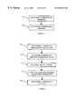
- FIG. 6illustrates a flow diagram for providing services with respect to the system perspective of FIG. 1 .
- the service bus 7exists as is illustrated in FIG. 1 .
- the service bus 7couples service entities 5 and interface entities 8 and accesses the service registry 9 .
- a new serviceis registered with the service registry 9 .
- the services list 31 of FIG. 5is updated with the new service 4 .
- a new useris registered with the service registry 9 .
- the users list 32is updated with the new user 33 , and the new user 33 lists the service entities 5 corresponding to the services 4 to which the new user 33 has subscribed.
- a usersubscribes to zero or more services 4 , and the number of service entities 5 listed for the user 33 corresponds to the number of services to which the user has subscribed.
- a new serviceis added or canceled for a registered user listed in the service registry 9 .
- a user 33is registered with the service provider 1 and is listed in the service registry 9 .
- the user 33wishes to add or cancel a service 4 provided by the service provider 1 .
- the users list 32is amended by adding a new service entity 5 corresponding to the desired new service 4 for the user 33 .
- the users list 32is amended by deleting the service entity 5 corresponding to the canceled service 4 for the user 33 .
- a new interface entityis dynamically installed onto the service bus.
- a new interface entityis needed if the service provider 1 is to interface with a communication system 3 that uses a communication protocol that is not supported by any of the existing interface entities 8 .
- the new interface entityincludes a new communication protocol 21 for interfacing with the new type of communication system.
- the new interface entityis installed without impacting the operation of the existing service entities 5 , existing interface entities 8 , and the service bus 7 . Further, by dynamically installing the new interface entity, the service bus 7 does not need to be reset.
- the service provider 1conducts sessions with users 2 .
- the service provider 1is capable of conducting one or more sessions at a time.
- the process for conducting a sessionis illustrated in FIG. 7 .
- FIG. 7illustrates a flow diagram for conducting a session.
- a user 2requests a session with the service provider 1 .
- the requestpasses from the user 2 to the service bus 7 via a communication system 3 and an interface entity 8 .
- the service provider 1verifies that the user 2 is authorized to access the service provider 1 .
- the service bus 7accesses the service registry 9 to verify that the user 2 is listed as a user 33 in the users list 32 . If the user is listed as a user 33 in the users list 32 , the flow proceeds to block 53 . If the user is not listed as a user 33 in the users list 32 , the user is denied access to the service provider 1 .
- the service provider 1dynamically installs the one or more service entities 5 of the user 2 onto the service bus 7 .
- the service provider 1accesses the users list 32 in the service registry 9 to determine the service entities 5 to dynamically install onto the service bus 7 .
- the service entityinforms the service bus as to which one or more interface entities the service entity requires for proper operation. If the requested interface entities are not already installed onto the service bus, the service provider 1 dynamically installs the requested interface entities onto the service bus.
- the service entitiesare installed without impacting the operation of the existing service entities 5 , existing interface entities 8 , and the service bus 7 . Further, by dynamically installing the service entities, the service bus 7 does not need to be reset.
- the service provider 1executes the requested service.
- the functions 11 - 13 of each service entity 33 for the requested service 32are accessed, as appropriate, from the functions 17 - 19 in the library 6 .
- the service provider 1performs one or more functions, as illustrated in blocks 56 - 60 of FIG. 7 .
- the service bus 7passes an event from an interface entity 8 to a service entity 5 . This is the initial step for almost all services.
- the service bus 7passes an event from a service entity 5 to an interface entity 8 .
- the service buspasses an event from a service entity 5 to another service entity 5 .
- the service bus 7manages precedence between the service entities 5 and interface entities 8 . For instance, if an event is to be passed to two or more service entities 5 or interface entities 8 , the service bus 7 determines the order of service entities 5 and interface entities 8 that are to receive the event. Also, each service entity can change the flow by altering the event, consuming the event, or allowing the event back out to the service bus 7 , where the next service entity will process it. If the service bus 7 cannot manage interactions between two or more entities, the service bus 7 dynamically installs an interaction service entity onto the service bus. The interaction service entity determines how two or more particular service entities interact given the current state and environment of the service bus 7 .
- the service provider 1performs error detection and correction, which is discussed further below with respect to FIGS. 8 and 9.
- an eventis passed from an interface entity to a service entity via the service bus and as determined by the service bus. After the event has been processed by all applicable service entities, the session is suspended awaiting the next event from an interface entity.
- the session with the service provider 1ends, and the user 2 is disconnected from the service provider 1 .
- the sessionends when, for example, the user 2 hangs up the telephone.
- the service provider 1dynamically uninstalls the service entities 5 for the user 2 from the service bus 7 .
- the service provider 1further dynamically uninstalls the interface entities 8 that are not required by any of the service entities 5 that remain installed on the service bus 7 .
- the service entities and any interface entitiesare uninstalled without impacting the operation of the existing service entities 5 , existing interface entities 8 , and the service bus 7 . Further, by dynamically uninstalling the service entities and any interface entities, the service bus 7 does not need to be reset.
- FIG. 8illustrates a flow diagram for error detection and correction for use with block 60 in FIG. 7 .
- a service entity 5 or an interface entity 8detects an error. Examples of an error include: receiving an incorrect event from the service bus; receiving an improperly formatted event; or receiving an unexpected event. An error is detected by a service entity or interface entity, which notifies the service bus of the error.
- the service entity 5 or interface entity 8 that detected the errorresets itself.
- the detecting service entity 5 or interface entity 8resets itself by taking a service specific action to recover gracefully from the error.
- FIG. 9illustrates a flow diagram for error detection and correction for use with block 60 in FIG. 7 .
- a service entity. 5 or an interface entity 8detects an incorrect received event from the service bus 7 .
- the service entity 5 or interface entity 8expected to receive a certain type of event from the service bus 7 , and instead received a different event.
- the service entity 5 or interface entity 8 that detected the errorsends an error message to the service bus 7 .
- the error messageis an unexpected event.
- the service buslogs the error message.
- the error messageis logged by an event management system of the service provider 1 , which is not shown in FIG. 1 .
- the service bus 7sends a reset message to the service entity 5 or interface entity 8 that detected the error.
- the reset messageis a reset event.
- FIGS. 10 and 11illustrate passing events using the service bus 7 .
- FIGS. 10 and 11illustrate three basic types of event passing: the service bus passing an event from an interface entity to a service entity; the service bus passing an event from a service entity to an interface entity; and the service bus passing an event from a service entity to another service entity.
- FIG. 10illustrates a service implemented by service entities 81 and 82 .
- the service bus 7couples the two service entities 81 and 82 and two interface entities 83 and 84 .
- the interface entity 83produces an event 85 , which is passed to the service entity 81 via the service bus 7 .
- the service entity 81produces an event 86 , which is passed to the service entity 82 via the service bus 7 .
- the service entity 82produces an event 87 , which is passed to the interface entity 84 via the service bus 7 .
- FIG. 11illustrates a service implemented by service entities 81 and 91 .
- the service bus 7couples three service entities 81 , 82 and 91 and two interface entities 83 and 84 .
- Interface entity 83produces an event 92 , which is passed to the service entity 81 via the service bus 7 .
- the service entity 81produces an event 93 , which is passed to the service entity 91 via the service bus 7 .
- the service entity 91produces event 94 , which is passed to the service entity 81 via the service bus 7 .
- the service entity 81produces an event 95 , which is passed to the interface entity 83 via the service bus 7 .
- the service bus 7determines the destination for the event.
- the service bus 7determines that an event must be passed from one entity to another entity by looking at the type and classification of the event.
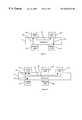
- FIG. 12illustrates a first example for providing services using the invention.
- an originating call from a user of the service provider 1is illustrated.
- An originating calloccurs for a call outgoing form the user.
- the userhas subscribed to four services of the service provider 1 , and the four services are implemented for the user with four service entities 101 - 104 .
- blocks 51 - 53 of FIG. 7are performed, and the service entities 101 - 104 and the interface entities 105 - 107 are dynamically installed onto the service bus 7 .
- the barring service entity 101provides a service which restricts certain types of calls.
- the directory service entity 102provides the ability to translate a name into a number using a directory.
- the personal identification number (PIN) service entity 103provides the ability to prompt a user for a PIN before making a toll or long distance call.
- the basic service entity 104provides basic call functions such as routing, answer, and release.
- the service bus 7couples the four service entities 101 - 104 to three interface entities 105 - 107 .
- the session initiation protocol (SIP) interface entity 105provides access to IP telephony functions and is coupled to a communication system for signaling call control information.
- the lightweight directory application protocol (LDAP) interface entity 106provides access to directory information and is coupled to a communication system for requesting and relaying directory info.
- the interactive voice response (IVR) interface entityprovides announcements and digit collection for prompt based services and is coupled to a communication system for requesting and controlling voice playback and digit reception equipment.
- an invite 108is received by the interface entity 105 .
- the invite 108is an initial call request protocol message.
- the interface entity 105produces an event 109 , which is passed to the service entity 101 via the service bus 7 .
- the service entity 101produces an event 110 , which is passed to the service entity 102 via the service bus 7 .
- the service entity 102produces an event 111 , which is passed to the interface entity 106 via the service bus 7 .
- the interface entity 106After receiving the event 111 , the interface entity 106 produces a directory request protocol message 112 requesting directory information and receives a directory response protocol message 113 with the directory information. After receiving the directory response protocol message 113 , the interface entity 106 produces an event 114 , which is passed to the service entity 102 via the service bus 7 . After receiving the event 114 , the service entity 102 produces an event 115 , which is passed to the service entity 103 via the service bus 7 . After receiving the event 115 , the service entity 103 produces an event 116 , which is passed to the interface entity 107 via the service bus 7 .
- the interface entity 107After receiving the event 116 , the interface entity 107 produces an IVR request protocol message 117 to collect a PIN and receives an IVR response protocol message 118 with the collected PIN. After receiving the IVR response protocol message 118 , the interface entity 107 produces an event 119 , which is passed to the service entity 103 via the service bus 7 . After receiving the event 119 , the service entity 103 produces an event 120 , which is passed to the service entity 104 via the service bus 7 . After receiving the event 120 , the service entity 104 produces an event 121 , which is passed by the service bus 7 as an invite. The invite for the event 121 is a continuation of the initial call request of invite 108 .
- FIG. 13illustrates a second example for providing services using the invention.
- a terminating callwhich is a call incoming to a user of the service provider 1 .
- the userhas subscribed to four services of the service provider 1 , and the four services are implemented for the user with four service entities 131 - 134 .
- blocks 51 - 53 of FIG. 7are performed, and the service entities 131 - 134 and the interface entities 135 - 137 are dynamically installed onto the service bus 7 .
- the forwarding service entity 131provides the capability to forward a call to another destination given certain criteria.
- the identity service entity 132provides the capability to notify a user of a call attempt by displaying the call information on a user premise device (e.g., a cable set top box).
- the logging service entity 133provides the capability to log via e-mail all call attempts.
- the basic service entity 134has the same functions as the basic service entity 104 illustrated in FIG. 12 . Even though basic service entities 104 and 134 implement the service offered by the service provider 1 , two service entities are used because two users have subscribed to the same service, namely the basic service, and a service entity is generated for each subscription to the basic service.
- the service buscouples the four service entities 131 - 134 to three interface entities 135 - 137 .
- the cable set top box (CSTB) interface entity 135provides an interface to a CSTB and is coupled to a communication system for displaying information on a television.
- the e-mail interface entity 136provides an interface to an e-mail server and is coupled to a communication system for dispatching e-mail.
- the SIP interface entity 137has the same functions as the SIP interface entity 105 illustrated in FIG. 12 .
- the service bus 7passes an event 138 to the service entity 131 .
- the event 138is an invite for an incoming call setup.
- the event 138can be a continuation of event 121 in FIG. 12, if the requested call of FIG. 12 is made to from a user of the service provider 1 to another user of the service provider 1 .
- the service entity 131produces an event 139 , which is passed to the service entity 132 via the service bus 7 .
- the service entity 132produces event 140 , which is passed to the interface entity 135 via the service bus 7 , and produces event 141 , which is passed to the service entity 133 via the service bus 7 .
- the interface entity 135After receiving the event 140 , the interface entity 135 produces a notification protocol message 142 to the CSTB to display the calling line information 142 .
- the notification protocol message 142causes a caller identification to be displayed on a television monitor of the user.
- the service entity 133After receiving the event 141 , the service entity 133 produces an event 143 , which is passed to the interface entity 135 via the service bus 7 , and produces an event 144 , which is passed to the service entity 134 via the service bus 7 .
- the interface entity 135After receiving the event 143 , the interface entity 135 produces an outgoing e-mail request protocol message 145 .
- the outgoing e-mail request protocol message 145results in an e-mail notification being sent to the user specified address.
- the service entity 104After receiving the event 144 , the service entity 104 produces an event 146 , which is passed to the interface entity 137 via the service bus 7 . After receiving the event 146 , the interface entity 105 produces an invite protocol message 147 .
- the invite protocol message 147is an invite to the terminating endpoint.
Landscapes
- Engineering & Computer Science (AREA)
- Computer Networks & Wireless Communication (AREA)
- Signal Processing (AREA)
- Computer Security & Cryptography (AREA)
- Computer And Data Communications (AREA)
- Communication Control (AREA)
- Nitrogen And Oxygen Or Sulfur-Condensed Heterocyclic Ring Systems (AREA)
- Exchange Systems With Centralized Control (AREA)
- Two-Way Televisions, Distribution Of Moving Picture Or The Like (AREA)
- Circuits Of Receivers In General (AREA)
Abstract
Description
Claims (21)
Priority Applications (11)
| Application Number | Priority Date | Filing Date | Title |
|---|---|---|---|
| US09/418,130US6625274B1 (en) | 1999-10-12 | 1999-10-12 | Computer system and method for providing services to users of communication systems using service entities, interface entities, and a service bus |
| EP00955313AEP1221236B1 (en) | 1999-10-12 | 2000-08-02 | System for providing services |
| AT00955313TATE345004T1 (en) | 1999-10-12 | 2000-08-02 | SERVICE PROVISION SYSTEM |
| DK00955313TDK1221236T3 (en) | 1999-10-12 | 2000-08-02 | System for providing services |
| PT00955313TPT1221236E (en) | 1999-10-12 | 2000-08-02 | System for providing services |
| DE60031788TDE60031788T2 (en) | 1999-10-12 | 2000-08-02 | SYSTEM FOR PROVISION OF SERVICES |
| CA002387409ACA2387409C (en) | 1999-10-12 | 2000-08-02 | System for providing services |
| AU67535/00AAU766370B2 (en) | 1999-10-12 | 2000-08-02 | System for providing services |
| PCT/US2000/020978WO2001028186A1 (en) | 1999-10-12 | 2000-08-02 | System for providing services |
| ES00955313TES2275535T3 (en) | 1999-10-12 | 2000-08-02 | SERVICE PROVISION SYSTEM. |
| CY20071100159TCY1105990T1 (en) | 1999-10-12 | 2007-02-06 | SYSTEM FOR THE PROVISION OF SERVICES |
Applications Claiming Priority (1)
| Application Number | Priority Date | Filing Date | Title |
|---|---|---|---|
| US09/418,130US6625274B1 (en) | 1999-10-12 | 1999-10-12 | Computer system and method for providing services to users of communication systems using service entities, interface entities, and a service bus |
Publications (1)
| Publication Number | Publication Date |
|---|---|
| US6625274B1true US6625274B1 (en) | 2003-09-23 |
Family
ID=23656836
Family Applications (1)
| Application Number | Title | Priority Date | Filing Date |
|---|---|---|---|
| US09/418,130Expired - LifetimeUS6625274B1 (en) | 1999-10-12 | 1999-10-12 | Computer system and method for providing services to users of communication systems using service entities, interface entities, and a service bus |
Country Status (11)
| Country | Link |
|---|---|
| US (1) | US6625274B1 (en) |
| EP (1) | EP1221236B1 (en) |
| AT (1) | ATE345004T1 (en) |
| AU (1) | AU766370B2 (en) |
| CA (1) | CA2387409C (en) |
| CY (1) | CY1105990T1 (en) |
| DE (1) | DE60031788T2 (en) |
| DK (1) | DK1221236T3 (en) |
| ES (1) | ES2275535T3 (en) |
| PT (1) | PT1221236E (en) |
| WO (1) | WO2001028186A1 (en) |
Cited By (39)
| Publication number | Priority date | Publication date | Assignee | Title |
|---|---|---|---|---|
| US20020069262A1 (en)* | 2000-10-13 | 2002-06-06 | Rigori Serge Andre | Extendable provisioning mechanism for a service gateway |
| US20020073205A1 (en)* | 2000-08-02 | 2002-06-13 | Miraj Mostafa | Communication service |
| US20020120729A1 (en)* | 2001-02-23 | 2002-08-29 | Stefano Faccin | Internet protocol based service architecture |
| US20020188661A1 (en)* | 2001-06-07 | 2002-12-12 | Nokia Corporation | Interaction arrangement |
| US20030018705A1 (en)* | 2001-03-31 | 2003-01-23 | Mingte Chen | Media-independent communication server |
| US20030041265A1 (en)* | 2001-08-21 | 2003-02-27 | Todd Lagimonier | System for efficiently handling cryptographic messages containing nonce values in a wireless connectionless environment without compromising security |
| US20030126196A1 (en)* | 2001-12-27 | 2003-07-03 | Todd Lagimonier | System for optimizing the invocation of computer-based services deployed in a distributed computing environment |
| US20050083912A1 (en)* | 2003-10-16 | 2005-04-21 | At&T Corp. | Method and apparatus for functional architecture of voice-over-IP SIP network border element |
| US20050114900A1 (en)* | 2003-11-24 | 2005-05-26 | Patrick Ladd | Methods and apparatus for hardware registration in a network device |
| US20060002520A1 (en)* | 2004-06-30 | 2006-01-05 | Bettis Sonny R | Message durability and retrieval in a geographically distributed voice messaging system |
| US7024209B1 (en)* | 2000-12-20 | 2006-04-04 | Cisco Technology, Inc. | Unified messaging system configured for management of short message service-type messages |
| US7042851B1 (en)* | 2000-10-26 | 2006-05-09 | Lucent Technologies Inc. | Service creation and negotiation in a wireless network |
| US20070037571A1 (en)* | 1998-01-22 | 2007-02-15 | Cingular Wireless Ii, Llc | Method and System for Remote Call Forwarding of Telephone Calls from an IP Connection |
| US7191209B1 (en)* | 2001-07-30 | 2007-03-13 | Bellsouth Intellectual Property Corp. | Application server and method to perform hierarchical configurable data manipulation |
| US20070155411A1 (en)* | 2006-01-04 | 2007-07-05 | James Morrison | Interactive mobile messaging system |
| US20070192415A1 (en)* | 2001-03-31 | 2007-08-16 | Pak Wai H | Extensible interface for inter-module communication |
| US20070192414A1 (en)* | 2001-03-31 | 2007-08-16 | Mingte Chen | User interface for multi-channel communication |
| US20070198945A1 (en)* | 2002-06-26 | 2007-08-23 | Zhaoyang Sun | User interface for multi-media communication for the disabled |
| US20070203797A1 (en)* | 2001-03-31 | 2007-08-30 | Annadata Anil K | Configurable media-independent server |
| US20080057943A1 (en)* | 2006-09-06 | 2008-03-06 | Cingular Wireless Ii, Llc | Remote call forwarding in a wireless network from a telecommunications device inside or outside the wireless network |
| US7353248B1 (en) | 2001-07-30 | 2008-04-01 | At&T Delaware Intellectual Property, Inc. | Application server and method to perform hierarchical configurable data validation |
| US20080159520A1 (en)* | 2001-03-31 | 2008-07-03 | Annadata Anil K | Adaptive communication application programming interface |
| US7441007B1 (en) | 2001-07-30 | 2008-10-21 | At&T Intellectual Property I, L.P. | System and method for allowing applications to retrieve properties and configuration information from a persistent store |
| US20090073896A1 (en)* | 2007-09-18 | 2009-03-19 | International Business Machines Corporation | Arrangements for auto-merging and auto-partitioning processing components |
| US20090077478A1 (en)* | 2007-09-18 | 2009-03-19 | International Business Machines Corporation | Arrangements for managing processing components using a graphical user interface |
| US20090252320A1 (en)* | 2001-02-06 | 2009-10-08 | Annadata Anil K | System and Method for Multi-Channel Communication Queuing |
| US20090313642A1 (en)* | 2001-02-06 | 2009-12-17 | Siebel Systems, Inc. | Adaptive Communication Application Programming Interface |
| US20110257766A1 (en)* | 2008-11-24 | 2011-10-20 | Abb Research Ltd. | System and a method for control and automation service |
| US20150271276A1 (en)* | 2014-03-18 | 2015-09-24 | Axis Ab | Capability monitoring in a service oriented architecture |
| US9269069B2 (en) | 2001-11-15 | 2016-02-23 | Siebel Systems, Inc. | Apparatus and method for displaying selectable icons in a toolbar for a user interface |
| US9674287B2 (en) | 2003-11-24 | 2017-06-06 | Time Warner Cable Enterprises Llc | Methods and apparatus for event logging in an information network |
| US10359922B2 (en) | 2004-02-06 | 2019-07-23 | Time Warner Cable Inc. | Methods and apparatus for display element management in an information network |
| US20190334778A1 (en)* | 2016-11-30 | 2019-10-31 | Nutanix, Inc. | Generic access to heterogeneous virtualized entities |
| US11818676B2 (en) | 2019-10-23 | 2023-11-14 | Charter Communications Operating, Llc | Methods and apparatus for device registration in a quasi-licensed wireless system |
| US11832034B2 (en) | 2018-04-16 | 2023-11-28 | Charter Communications Operating, Llc | Apparatus and methods for coordinated delivery of multiple data channels over physical medium |
| US11889492B2 (en) | 2019-02-27 | 2024-01-30 | Charter Communications Operating, Llc | Methods and apparatus for wireless signal maximization and management in a quasi-licensed wireless system |
| US11903049B2 (en) | 2018-10-12 | 2024-02-13 | Charter Communications Operating, Llc | Apparatus and methods for cell identification in wireless networks |
| US12170986B2 (en) | 2019-01-31 | 2024-12-17 | Charter Communications Operating, Llc | Methods and apparatus for frequency transition management in a quasi-licensed wireless system |
| US12200814B2 (en) | 2018-08-07 | 2025-01-14 | Charter Communications Operating, Llc | Apparatus and methods for registration and operation in wireless networks |
Families Citing this family (6)
| Publication number | Priority date | Publication date | Assignee | Title |
|---|---|---|---|---|
| GB0100309D0 (en)* | 2001-01-05 | 2001-02-14 | Nokia Networks Oy | Provision of services in a communications system |
| US7379543B2 (en) | 2001-03-09 | 2008-05-27 | Ayman, Llc. | Universal point of contact identifier system and method |
| AU2002302741A1 (en)* | 2001-05-24 | 2002-12-09 | International Business Machines Corporation | Service application architecture for integrated network service providers |
| EP1552659B1 (en) | 2002-10-16 | 2015-01-14 | Aepona Limited | A service access gateway |
| US20120131645A1 (en) | 2010-11-18 | 2012-05-24 | Harm Michael W | User Scriptable Server Initiated User Interface Creation |
| WO2012067618A1 (en)* | 2010-11-18 | 2012-05-24 | Google Inc. | User scriptable server initiated user interface creation |
Citations (3)
| Publication number | Priority date | Publication date | Assignee | Title |
|---|---|---|---|---|
| US5442690A (en)* | 1992-08-25 | 1995-08-15 | Bell Communications Research, Inc. | Telecommunication service record structure and method of execution |
| US5511116A (en)* | 1992-08-25 | 1996-04-23 | Bell Communications Research Inc. | Method of creating and accessing value tables in a telecommunication service creation and execution environment |
| EP0810799A2 (en) | 1996-05-31 | 1997-12-03 | Lucent Technologies Inc. | Arrangement for facilitating plug-and-plug call features |
- 1999
- 1999-10-12USUS09/418,130patent/US6625274B1/ennot_activeExpired - Lifetime
- 2000
- 2000-08-02ESES00955313Tpatent/ES2275535T3/ennot_activeExpired - Lifetime
- 2000-08-02ATAT00955313Tpatent/ATE345004T1/enactive
- 2000-08-02PTPT00955313Tpatent/PT1221236E/enunknown
- 2000-08-02DEDE60031788Tpatent/DE60031788T2/ennot_activeExpired - Lifetime
- 2000-08-02AUAU67535/00Apatent/AU766370B2/ennot_activeCeased
- 2000-08-02CACA002387409Apatent/CA2387409C/ennot_activeExpired - Lifetime
- 2000-08-02EPEP00955313Apatent/EP1221236B1/ennot_activeExpired - Lifetime
- 2000-08-02DKDK00955313Tpatent/DK1221236T3/enactive
- 2000-08-02WOPCT/US2000/020978patent/WO2001028186A1/enactiveIP Right Grant
- 2007
- 2007-02-06CYCY20071100159Tpatent/CY1105990T1/enunknown
Patent Citations (3)
| Publication number | Priority date | Publication date | Assignee | Title |
|---|---|---|---|---|
| US5442690A (en)* | 1992-08-25 | 1995-08-15 | Bell Communications Research, Inc. | Telecommunication service record structure and method of execution |
| US5511116A (en)* | 1992-08-25 | 1996-04-23 | Bell Communications Research Inc. | Method of creating and accessing value tables in a telecommunication service creation and execution environment |
| EP0810799A2 (en) | 1996-05-31 | 1997-12-03 | Lucent Technologies Inc. | Arrangement for facilitating plug-and-plug call features |
Non-Patent Citations (4)
| Title |
|---|
| G.D. Turner, "Service Creation," BT Technology Journal, vol. 13, No. 2, Apr. 1995, pp. 80-86. |
| M. Elixmann and J. Fischer, "Service Creation Environment-A Development Environment for Services in the Intelligent Network," Philips Telecommunication Review, vol. 50, No. 1, Mar. 1992, pp. 34-38. |
| M. Elixmann and J. Fischer, "Service Creation Environment—A Development Environment for Services in the Intelligent Network," Philips Telecommunication Review, vol. 50, No. 1, Mar. 1992, pp. 34-38. |
| M. Genette, "Service Creation Environment: Flexibility, Openness and Evolution," Electrical Communication, Be, Alcatel. Brussels, Jan. 1999, pp. 53-59. |
Cited By (73)
| Publication number | Priority date | Publication date | Assignee | Title |
|---|---|---|---|---|
| US20070037571A1 (en)* | 1998-01-22 | 2007-02-15 | Cingular Wireless Ii, Llc | Method and System for Remote Call Forwarding of Telephone Calls from an IP Connection |
| US7515905B2 (en)* | 1998-01-22 | 2009-04-07 | At & T Mobility Ii Llc | Method and system for remote call forwarding of telephone calls from an IP connection |
| US20020073205A1 (en)* | 2000-08-02 | 2002-06-13 | Miraj Mostafa | Communication service |
| US10581792B2 (en) | 2000-08-02 | 2020-03-03 | Conversant Wireless Licensing S.A R.L. | Streaming of media in a multimedia messaging service |
| US9800538B2 (en)* | 2000-08-02 | 2017-10-24 | Conversant Wireless Licensing S.A R.L. | Communication service |
| US20020069262A1 (en)* | 2000-10-13 | 2002-06-06 | Rigori Serge Andre | Extendable provisioning mechanism for a service gateway |
| US7191232B2 (en)* | 2000-10-13 | 2007-03-13 | Sun Microsystems, Inc. | Extendable provisioning mechanism for a service gateway |
| US7042851B1 (en)* | 2000-10-26 | 2006-05-09 | Lucent Technologies Inc. | Service creation and negotiation in a wireless network |
| US7024209B1 (en)* | 2000-12-20 | 2006-04-04 | Cisco Technology, Inc. | Unified messaging system configured for management of short message service-type messages |
| US20060128409A1 (en)* | 2000-12-20 | 2006-06-15 | Gress David S | Unified messaging system configured for management of short message service-type messages |
| US7269432B2 (en)* | 2000-12-20 | 2007-09-11 | Cisco Technology, Inc. | Unified messaging system configured for management of short message service-type messages |
| US20090313642A1 (en)* | 2001-02-06 | 2009-12-17 | Siebel Systems, Inc. | Adaptive Communication Application Programming Interface |
| US20090252320A1 (en)* | 2001-02-06 | 2009-10-08 | Annadata Anil K | System and Method for Multi-Channel Communication Queuing |
| US8365205B2 (en) | 2001-02-06 | 2013-01-29 | Siebel Systems, Inc. | Adaptive communication application programming interface |
| US7849190B2 (en)* | 2001-02-23 | 2010-12-07 | Nokia Siemens Networks Oy | Internet protocol based service architecture |
| US20020120729A1 (en)* | 2001-02-23 | 2002-08-29 | Stefano Faccin | Internet protocol based service architecture |
| US7788679B2 (en) | 2001-03-31 | 2010-08-31 | Siebel Systems, Inc. | User interface with context-based communication using media prediction |
| US20080159520A1 (en)* | 2001-03-31 | 2008-07-03 | Annadata Anil K | Adaptive communication application programming interface |
| US20070192415A1 (en)* | 2001-03-31 | 2007-08-16 | Pak Wai H | Extensible interface for inter-module communication |
| US20070192414A1 (en)* | 2001-03-31 | 2007-08-16 | Mingte Chen | User interface for multi-channel communication |
| US20030018705A1 (en)* | 2001-03-31 | 2003-01-23 | Mingte Chen | Media-independent communication server |
| US20070204272A1 (en)* | 2001-03-31 | 2007-08-30 | Mingte Chen | Synchronization of communication connection state with communication user interface |
| US20070204273A1 (en)* | 2001-03-31 | 2007-08-30 | Siebel Systems, Inc. | Context-sensitive user interface |
| US20070203797A1 (en)* | 2001-03-31 | 2007-08-30 | Annadata Anil K | Configurable media-independent server |
| US7730204B2 (en) | 2001-03-31 | 2010-06-01 | Siebel Systems, Inc. | Extensible interface for inter-module communication |
| US8601492B2 (en)* | 2001-03-31 | 2013-12-03 | Siebel Systems, Inc. | User interface for multi-channel communication |
| US8045698B2 (en) | 2001-03-31 | 2011-10-25 | Siebel Systems, Inc. | Adaptive communication application programming interface |
| US8839270B2 (en) | 2001-03-31 | 2014-09-16 | Siebel Systems, Inc. | Synchronization of communication connection state with communication user interface |
| US20020188661A1 (en)* | 2001-06-07 | 2002-12-12 | Nokia Corporation | Interaction arrangement |
| US6941337B2 (en)* | 2001-06-07 | 2005-09-06 | Nokia Corporation | Interaction arrangement for a sequence of interactions providing a service to a user |
| US7441007B1 (en) | 2001-07-30 | 2008-10-21 | At&T Intellectual Property I, L.P. | System and method for allowing applications to retrieve properties and configuration information from a persistent store |
| US7191209B1 (en)* | 2001-07-30 | 2007-03-13 | Bellsouth Intellectual Property Corp. | Application server and method to perform hierarchical configurable data manipulation |
| US7353248B1 (en) | 2001-07-30 | 2008-04-01 | At&T Delaware Intellectual Property, Inc. | Application server and method to perform hierarchical configurable data validation |
| US7856660B2 (en) | 2001-08-21 | 2010-12-21 | Telecommunication Systems, Inc. | System for efficiently handling cryptographic messages containing nonce values |
| US20160021063A1 (en)* | 2001-08-21 | 2016-01-21 | Telecommunication Systems, Inc. | System for Efficiently Handling Cryptographic Messages Containing Nonce Values in a Wireless Connectionless Environment |
| US8453240B2 (en) | 2001-08-21 | 2013-05-28 | Telecommunication Systems, Inc. | System for efficiently handling cryptographic messages containing nonce values in a wireless connectionless environment without comprising security |
| US20030041265A1 (en)* | 2001-08-21 | 2003-02-27 | Todd Lagimonier | System for efficiently handling cryptographic messages containing nonce values in a wireless connectionless environment without compromising security |
| US9071438B2 (en) | 2001-08-21 | 2015-06-30 | Telecommunication Systems, Inc. | System for efficiently handling cryptographic messages containing nonce values in a wireless connectionless environment |
| US20110088094A1 (en)* | 2001-08-21 | 2011-04-14 | Todd Lagimonier | System for efficiently handling cryptographic messages containing nonce values in a wireless connectionless environment without comprising security |
| US8161553B2 (en) | 2001-08-21 | 2012-04-17 | Telecommunication Systems, Inc. | System for efficiently handling cryptographic messages containing nonce values in a wireless connectionless environment without comprising security |
| US9269069B2 (en) | 2001-11-15 | 2016-02-23 | Siebel Systems, Inc. | Apparatus and method for displaying selectable icons in a toolbar for a user interface |
| US20030126196A1 (en)* | 2001-12-27 | 2003-07-03 | Todd Lagimonier | System for optimizing the invocation of computer-based services deployed in a distributed computing environment |
| US7673241B2 (en) | 2002-06-26 | 2010-03-02 | Siebel Systems, Inc. | User interface for multi-media communication for the visually disabled |
| US20070198945A1 (en)* | 2002-06-26 | 2007-08-23 | Zhaoyang Sun | User interface for multi-media communication for the disabled |
| US20050083912A1 (en)* | 2003-10-16 | 2005-04-21 | At&T Corp. | Method and apparatus for functional architecture of voice-over-IP SIP network border element |
| US7830861B2 (en)* | 2003-10-16 | 2010-11-09 | At&T Intellectual Property Ii, L.P. | Method and apparatus for functional architecture of voice-over-IP SIP network border element |
| US11252055B2 (en) | 2003-11-24 | 2022-02-15 | Time Warner Cable Enterprises Llc | Methods and apparatus for hardware registration in a network device |
| US8302111B2 (en) | 2003-11-24 | 2012-10-30 | Time Warner Cable Inc. | Methods and apparatus for hardware registration in a network device |
| US9674287B2 (en) | 2003-11-24 | 2017-06-06 | Time Warner Cable Enterprises Llc | Methods and apparatus for event logging in an information network |
| US20050114900A1 (en)* | 2003-11-24 | 2005-05-26 | Patrick Ladd | Methods and apparatus for hardware registration in a network device |
| US9479404B2 (en) | 2003-11-24 | 2016-10-25 | Time Warner Cable Enterprises Llc | Methods and apparatus for hardware registration in a network device |
| US10359922B2 (en) | 2004-02-06 | 2019-07-23 | Time Warner Cable Inc. | Methods and apparatus for display element management in an information network |
| US11287962B2 (en) | 2004-02-06 | 2022-03-29 | Time Warner Cable Enterprises Llc | Methods and apparatus for display element management in an information network |
| US20060002520A1 (en)* | 2004-06-30 | 2006-01-05 | Bettis Sonny R | Message durability and retrieval in a geographically distributed voice messaging system |
| US7308083B2 (en)* | 2004-06-30 | 2007-12-11 | Glenayre Electronics, Inc. | Message durability and retrieval in a geographically distributed voice messaging system |
| US20070155411A1 (en)* | 2006-01-04 | 2007-07-05 | James Morrison | Interactive mobile messaging system |
| US20080057943A1 (en)* | 2006-09-06 | 2008-03-06 | Cingular Wireless Ii, Llc | Remote call forwarding in a wireless network from a telecommunications device inside or outside the wireless network |
| US20090073896A1 (en)* | 2007-09-18 | 2009-03-19 | International Business Machines Corporation | Arrangements for auto-merging and auto-partitioning processing components |
| US8023434B2 (en) | 2007-09-18 | 2011-09-20 | International Business Machines Corporation | Arrangements for auto-merging and auto-partitioning processing components |
| US20090077478A1 (en)* | 2007-09-18 | 2009-03-19 | International Business Machines Corporation | Arrangements for managing processing components using a graphical user interface |
| US8161393B2 (en) | 2007-09-18 | 2012-04-17 | International Business Machines Corporation | Arrangements for managing processing components using a graphical user interface |
| US20110257766A1 (en)* | 2008-11-24 | 2011-10-20 | Abb Research Ltd. | System and a method for control and automation service |
| US11650575B2 (en)* | 2008-11-24 | 2023-05-16 | Abb Research Ltd. | System and a method for control and automation service |
| TWI631475B (en)* | 2014-03-18 | 2018-08-01 | 安訊士有限公司 | System and method for capability monitoring |
| US9705995B2 (en)* | 2014-03-18 | 2017-07-11 | Axis Ab | Capability monitoring in a service oriented architecture |
| US20150271276A1 (en)* | 2014-03-18 | 2015-09-24 | Axis Ab | Capability monitoring in a service oriented architecture |
| US20190334778A1 (en)* | 2016-11-30 | 2019-10-31 | Nutanix, Inc. | Generic access to heterogeneous virtualized entities |
| US11832034B2 (en) | 2018-04-16 | 2023-11-28 | Charter Communications Operating, Llc | Apparatus and methods for coordinated delivery of multiple data channels over physical medium |
| US12200814B2 (en) | 2018-08-07 | 2025-01-14 | Charter Communications Operating, Llc | Apparatus and methods for registration and operation in wireless networks |
| US11903049B2 (en) | 2018-10-12 | 2024-02-13 | Charter Communications Operating, Llc | Apparatus and methods for cell identification in wireless networks |
| US12170986B2 (en) | 2019-01-31 | 2024-12-17 | Charter Communications Operating, Llc | Methods and apparatus for frequency transition management in a quasi-licensed wireless system |
| US11889492B2 (en) | 2019-02-27 | 2024-01-30 | Charter Communications Operating, Llc | Methods and apparatus for wireless signal maximization and management in a quasi-licensed wireless system |
| US11818676B2 (en) | 2019-10-23 | 2023-11-14 | Charter Communications Operating, Llc | Methods and apparatus for device registration in a quasi-licensed wireless system |
Also Published As
| Publication number | Publication date |
|---|---|
| ATE345004T1 (en) | 2006-11-15 |
| DE60031788T2 (en) | 2007-09-06 |
| EP1221236A1 (en) | 2002-07-10 |
| ES2275535T3 (en) | 2007-06-16 |
| AU6753500A (en) | 2001-04-23 |
| CA2387409C (en) | 2006-10-31 |
| EP1221236B1 (en) | 2006-11-08 |
| DK1221236T3 (en) | 2007-03-19 |
| WO2001028186A1 (en) | 2001-04-19 |
| CA2387409A1 (en) | 2001-04-19 |
| DE60031788D1 (en) | 2006-12-21 |
| CY1105990T1 (en) | 2011-04-06 |
| PT1221236E (en) | 2007-02-28 |
| AU766370B2 (en) | 2003-10-16 |
Similar Documents
| Publication | Publication Date | Title |
|---|---|---|
| US6625274B1 (en) | Computer system and method for providing services to users of communication systems using service entities, interface entities, and a service bus | |
| US6430276B1 (en) | Telecommunications system and method providing generic network access service | |
| RU2144271C1 (en) | System for control over telecommunication maintenance | |
| US7496652B2 (en) | Intelligent network providing network access services (INP-NAS) | |
| EP1558001B1 (en) | Method and apparatus for operating an open network having a proxy | |
| US7457279B1 (en) | Method, system, and computer program product for managing routing servers and services | |
| US5915008A (en) | System and method for changing advanced intelligent network services from customer premises equipment | |
| EP1040680B1 (en) | Architecture-independent application invocation over a telephony network | |
| EP1913485B1 (en) | Policy engine | |
| JP5726991B2 (en) | Communication network | |
| US6111946A (en) | Method and system for providing answer supervision in a switched telephone network | |
| WO2000019677A2 (en) | Connection manager for telecommunications | |
| CN1973526B (en) | Event processing method for processing service initial request message in event processing system | |
| WO2001076205A1 (en) | Telecommunications system and methods | |
| KR20000069024A (en) | A communication system architecture | |
| JP2009543452A (en) | Method and apparatus for a single chassis communication server having a connection only interface | |
| US20020160810A1 (en) | Intelligent network service control point and method of implementing user services utilizing call processing language scripts | |
| GB2387064A (en) | Method and system for construction and communication of data on network access and service transactions in a telecommunication network | |
| Cisco | Cisco BTS 10200 Softswitch Release Notes for Release 3.3 | |
| Cisco | Cisco BTS 10200 Automatic Callback, Automatic Recall Feature Module | |
| EP1851946B1 (en) | System and apparatus for processing network events | |
| EP2026548A1 (en) | A method, system and device for implementing controlled charging | |
| CN100428762C (en) | Call response method, call center operation method, node device, and call center device | |
| US6744855B1 (en) | Service control platform | |
| US20060002374A1 (en) | System and method for event notification in a J2EE environment |
Legal Events
| Date | Code | Title | Description |
|---|---|---|---|
| AS | Assignment | Owner name:BROADSOFT, INC., MARYLAND Free format text:ASSIGNMENT OF ASSIGNORS INTEREST;ASSIGNORS:HOFFPAUIR, SCOTT;JORDAN, JEFFREY L.;REEL/FRAME:010330/0178 Effective date:19991011 | |
| AS | Assignment | Owner name:COMDISCO, INC., ILLINOIS Free format text:SECURITY AGREEMENT;ASSIGNOR:BROADSOFT, INC.;REEL/FRAME:010862/0595 Effective date:20000605 | |
| STCF | Information on status: patent grant | Free format text:PATENTED CASE | |
| AS | Assignment | Owner name:COMDISCO, INC., ILLINOIS Free format text:RELEASE OF SECURITY AGREEMENT;ASSIGNOR:BROADSOFT, INC.;REEL/FRAME:015027/0934 Effective date:20030507 | |
| AS | Assignment | Owner name:SILICON VALLEY BANK, CALIFORNIA Free format text:SECURITY AGREEMENT;ASSIGNOR:BROADSOFT, INC.;REEL/FRAME:015293/0100 Effective date:20040328 | |
| FPAY | Fee payment | Year of fee payment:4 | |
| AS | Assignment | Owner name:BROADSOFT INC, MARYLAND Free format text:RELEASE BY SECURED PARTY;ASSIGNOR:SILICON VALLEY BANK;REEL/FRAME:021603/0871 Effective date:20080930 | |
| AS | Assignment | Owner name:ORIX VENTURE FINANCE LLC, NEW YORK Free format text:SECURITY AGREEMENT;ASSIGNOR:BROADSOFT, INC.;REEL/FRAME:021701/0844 Effective date:20080926 | |
| FEPP | Fee payment procedure | Free format text:PAYOR NUMBER ASSIGNED (ORIGINAL EVENT CODE: ASPN); ENTITY STATUS OF PATENT OWNER: LARGE ENTITY | |
| AS | Assignment | Owner name:BROADSOFT INC,MARYLAND Free format text:RELEASE;ASSIGNOR:SILICON VALLEY BANK;REEL/FRAME:023998/0770 Effective date:20100219 | |
| AS | Assignment | Owner name:BROADSOFT, INC., MARYLAND Free format text:RELEASE BY SECURED PARTY;ASSIGNOR:ORIX VENTURE FINANCE LLC;REEL/FRAME:024900/0525 Effective date:20100827 | |
| AS | Assignment | Owner name:BROADSOFT, INC., MARYLAND Free format text:CHANGE OF ADDRESS RECORDATION DOCUMENT;ASSIGNOR:BROADSOFT, INC.;REEL/FRAME:025383/0975 Effective date:20101115 | |
| FPAY | Fee payment | Year of fee payment:8 | |
| FPAY | Fee payment | Year of fee payment:12 | |
| FEPP | Fee payment procedure | Free format text:ENTITY STATUS SET TO UNDISCOUNTED (ORIGINAL EVENT CODE: BIG.); ENTITY STATUS OF PATENT OWNER: LARGE ENTITY |