US6625209B1 - Short synchronization time data modem - Google Patents
Short synchronization time data modemDownload PDFInfo
- Publication number
- US6625209B1 US6625209B1US09/280,400US28040099AUS6625209B1US 6625209 B1US6625209 B1US 6625209B1US 28040099 AUS28040099 AUS 28040099AUS 6625209 B1US6625209 B1US 6625209B1
- Authority
- US
- United States
- Prior art keywords
- modem
- clock
- signal
- data
- utcc1
- Prior art date
- Legal status (The legal status is an assumption and is not a legal conclusion. Google has not performed a legal analysis and makes no representation as to the accuracy of the status listed.)
- Expired - Fee Related
Links
- 238000000034methodMethods0.000claimsdescription15
- 230000005540biological transmissionEffects0.000claimsdescription12
- 238000012549trainingMethods0.000claimsdescription11
- 230000004044responseEffects0.000claimsdescription7
- 230000003213activating effectEffects0.000claims2
- 230000001360synchronised effectEffects0.000abstractdescription6
- 238000011084recoveryMethods0.000abstractdescription3
- 238000004891communicationMethods0.000description9
- 238000010586diagramMethods0.000description4
- 238000012544monitoring processMethods0.000description4
- 238000001514detection methodMethods0.000description3
- 230000008569processEffects0.000description3
- 230000000630rising effectEffects0.000description3
- 238000012546transferMethods0.000description3
- 229910052792caesiumInorganic materials0.000description2
- TVFDJXOCXUVLDH-UHFFFAOYSA-Ncaesium atomChemical compound[Cs]TVFDJXOCXUVLDH-UHFFFAOYSA-N0.000description2
- 230000001413cellular effectEffects0.000description2
- 239000000969carrierSubstances0.000description1
- 230000008859changeEffects0.000description1
- 239000013078crystalSubstances0.000description1
- 230000003111delayed effectEffects0.000description1
- 230000009977dual effectEffects0.000description1
- 230000007704transitionEffects0.000description1
Images


Classifications
- G—PHYSICS
- G04—HOROLOGY
- G04G—ELECTRONIC TIME-PIECES
- G04G5/00—Setting, i.e. correcting or changing, the time-indication
- G04G5/002—Setting, i.e. correcting or changing, the time-indication brought into action by radio
- H—ELECTRICITY
- H04—ELECTRIC COMMUNICATION TECHNIQUE
- H04W—WIRELESS COMMUNICATION NETWORKS
- H04W4/00—Services specially adapted for wireless communication networks; Facilities therefor
- H04W4/02—Services making use of location information
Definitions
- Inventionrelates to data modems, and more particularly to data modem clock synchronization.
- Data modemsare commonly used to send and receive data via telephone lines or other communications facilities. Each modem has a local clock, which is free running, not synchronized to any other timing source. When two modems first connect, they first must synchronize their local clocks to ensure reliable transfer of data communication.
- the modemsuse a variety of clock recovery schemes, such as phase-locked loop circuits, to lock to opposing modem clock. This type of scheme requires a period of time when the modems send certain known sequences of signals, such as alternate ones and zeros and scrambled ones, to allow their respective clock recovery circuits to phase lock to the modem clock at the other end. After this clock synchronization period, the modems begin sending actual data.
- clock synchronization timeis insignificant when compared to the time it takes for the two modems to transfer data.
- clock synchronization timeis in the range of a few seconds or less, while the actual data communication time is in the order of several minutes or perhaps several hours.
- clock synchronization timebecomes a significant overhead, particularly when typical synchronization takes as much time, or more, than time to send the actual data.
- An example of such applicationsis mobile asset tracking, where an asset is equipped with a GPS receiver to detect its own location, and a wireless modem to report its location to a central monitoring station. Data required to report asset location information, such as latitude and longitude data, is very small (less than 100 bytes), and thus correspondingly involves very little data transmission.
- This inventionprovides data modems having very fast clock synchronization, by having the modem receiver clock synchronize to a precise clock signal derived from a received broadcasted signal comprising a very high precision clock, such as an UTC clock from a global positioning satellite (GPS).
- the modemsconnect for the first time using a standard training procedure. Thereafter, once on-line communication between the modems has been disconnected, the modems maintain their local clock synchronization to the GPS's UTC clock provided to a local GPS receiver.
- GPS receivers at both end of the modem terminalsare synchronized to the same received broadcasted signal comprising the same high precision clock from the GPS, this prevents the local modem clocks from drifting apart, thereby significantly reduces the modem synchronization time, or the training time at the next modem connect time.
- the GPS receiverprovides dual functions of producing a location fix, as well as providing precise timing to a wireless modem. And since the modem at the central monitoring station is also equipped with a GPS receiver, the central modem maintains synchronization with the remote modem using the same precise clock available from its GPS receiver. Because the GPS constellation consists of 24 orbiting satellites that continuously broadcast signals, the signal processor of GPS receiver use these broadcasted signals to determine its own latitude and longitude position. And since each GPS satellite is also equipped with a highly stable Cesium clock, the GPS receivers use this precise clocks to correct their local clock, which is not as stable as the GPS atomic clocks.
- the GPS receiversgenerate a clock that is locked to the GPS atomic clock and operates at 1 pulse per second (PPS) rate.
- PPSpulse per second
- the accuracy of this clockis bounded by the Selective Availability (SA) which limits the position accuracy of a non-differential GPS receiver to about 100 meters which translates to a clock error of about 333 nanoseconds. This error, when compared to the bit period, and bit clock, of a voice-band modem, is insignificant.
- SASelective Availability
- FIG. 1shows a block diagram of a short synchronization time data modem system in accordance to the principles of this present invention
- FIG. 2Aillustrates a standard modem synchronization protocol provided by ITU V.22 standard
- FIG. 2Bshows a continuation of FIG. 2A diagram illustrating standard modem synchronization protocol provided by ITU V.22 standard;
- FIG. 3shows a more detailed block diagram of the PLL of FIG. 1;
- FIG. 4illustrates a sample timing relationship of signals shown in PLL of FIG. 3;
- FIG. 5Aillustrates a flow chart of the operational steps of the PLL of FIG. 3
- FIG. 5Bshows a continuation of FIG. 5A flow chart describing the operational steps of the PLL of FIG. 3;
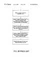
- FIG. 6illustrates a short training synchronization sequence for maintaining synchronization in accordance with the principles of this invention.
- a first data modem systemcommunicates with one or more remote data modem systems, wherein each data modem system comprises a short synchronization time data modem system 10 of FIG. 1 provided in accordance to the principles of this invention.
- the first modem system 10communicating with one or more modem systems 10 remotely located to the first modem system 10 , such as located at a central monitoring station, maintains synchronization with that one or more remotely located modem system 10 using a precise broadcasted clock available to each GPS receiver 12 provided via incoming broadcasted signal 11 .
- GPS receiver 12comprises a typical RF front-end circuit coupled to a signal processor via a demodulator (not shown), wherein the RF front-end operates at a pre-selected frequency to receive incoming broadcasted signals 11 via antenna 21 .
- the RF front-end of GPS receiver 12operates at a GPS frequency of 1575.42 MHz to receive GPS broadcasted signal as incoming signal 11 via antenna 21 .
- GPS receiver 12provides to PLL 14 a digitized clock signal 13 (UTCC), such as an Universal Time Coordinate (UTC) signal that is phase locked to the atomic clock of the Global Positioning derived from incoming receiver signal 11 for local clock synchronization.
- UTCCdigitized clock signal 13
- UTCUniversal Time Coordinate
- the signal processor of GPS receiver 12then processes incoming broadcasted signal 11 comprising GPS signals received from GPS satellites to derive positional data (i.e., latitude, longitude), and the Universal Time Coordinate signal (UTC). Since the GPS constellation comprises 24 orbiting satellites that continuously broadcast GPS signals, the signal processor of GPS receiver 12 can thereby use broadcasted GPS signals to determine its own latitude and longitude position. Moreover, because each GPS satellite is also equipped with a highly precise and stable Cesium clock, each GPS receiver 12 in essence simultaneously also receives this precise clock via incoming broadcasted signal 11 . As described herein, incoming receiver signal 11 preferably comprises a GPS broadcasted signal.
- any broadcasted, high precision clocksuch as the (“WWT”) atomic clock in Boulder, Colo., or the Greenwich clock, located in the United Kingdom, received via antenna 21 as incoming receiver signal 11 can be used by GPS receiver 12 to generate digitized UTCC clock 13 for local clock synchronization.
- a first modem system 10communicating with one or more modem systems 10 remotely located to the first modem system 10 , such as located at a central monitoring station, maintains synchronization with that one or more remotely located modem system 10 using the same precise broadcasted clock available to each GPS receiver 12 provided via incoming broadcasted signal 11 .
- GPS receiver 12provides to PLL 14 digitized UTC signal 13 (UTCC) derived from incoming broadcasted signal 11 for local clock synchronization.
- UTCCdigitized UTC signal 13
- PLL 14receives UTCC 13 and phase-locks a local clock 17 (CCLK) to UTCC to generate a modem clock 15 (MCLK) for clocking data transmission.
- MCLKis then provided to modem circuit 16 to clock data transmission.
- Modem 16comprises a typical modem circuitry having a modulator section which converts a digital stream of transmit data into an analog signal suitable for transmission over an analog channel 18 such as a phone line or a cellular phone channel.
- Modem circuit 16also comprises a demodulator circuit, which receives an analog signal over an analog channel and converts it to a digital stream of received data.
- a typical data communicationis between two modems that are remotely located to one another.
- the first data modem systemwill be referred to as terminal A and the second data modem system referred as terminal B.
- terminal Acalls terminal B over an analog channel 18 , such as via a phone line or a cellular channel
- modem circuit 16 of terminal Banswers the call.
- Terminal A and Bthen each executes an initial, predetermined training sequence (or “handshake”), such as provided by the ITU V.22 modem standard protocol illustrated in FIGS.
- 2A-2Bwhich consists of terminal B sending an acknowledging response tone followed by a fixed pattern of data, i.e., a sequence of “ones” and “zeroes”.
- terminal Asends terminal B another known signal pattern.
- This “handshaking”continues in varying lengths and complexity depending on the modem specifications until the modem receiver of terminal B is locked to terminal A and vice versa.
- the term “locked”means herein that each modem clock is synchronized to the other, the equalizers in both modems are trained, and the modems' carriers are phase locked to each other. Once the modem clocks are mutually locked, or synchronized to the other, then the two modems are ready to transmit or receive data.
- FIG. 3illustrates a more detailed embodiment of PLL circuit 14 of FIG. 1 .
- the typical operating frequency of a GPS clock 13 (UTCC)is at 1 Hz, which is much lower than the clock frequency needed for modem operation.
- PLL 14therefore generates a higher frequency modem clock 15 (MCLK) to clock modem 16 .
- MCLK 15comprises a frequency that is a multiple N of UTCC frequency.
- MCLK 15is generated using a higher frequency clock 41 (HCLK) generated from a crystal clock oscillator operating at, for example, 2.457 MHz.
- HCLK 41is selected initially to be 128 times the desired MCLK frequency.
- HCLK 41is then divided down by a 7-bit counter 42 to generate MCLK 15 .
- MCLK 15can be subsequently speeded up by adding a count to 7-bit Counter 42 , or slowed down by reducing count to Counter 42 depending on control logic signals Add Count 51 and Skip Count signal 53 received from edge detector 48 .
- MCLK 15is also divided by a multiple N (i.e., 1200) to generate a local modem clock 17 (CCLK), which at 1 Hz is at the same frequency, and therefore in synchronization to GPS clock UTCC 13 .
- Ni.e., 1200
- FIG. 4illustrates a typical phase offset 60 ( ⁇ ) between CCLK 17 and UTCCD 47 clock signals that is detected by phase detector circuit 46 (see FIG. 3) prior to the modem connection between terminals A and B being terminated.
- PLL 14phase locks CCLK 17 to UTCCD 47 such that the ⁇ phase offset between CCLK and UTCC remains fixed.
- modem 16 at each terminal A and Blocks its CCLK 17 to UTCCD signal 47 using a phase detection and adjustment circuit 49 (FIG. 3) of PLL 14 to keep local CCLK 17 in each system from drifting.
- FIG. 3illustrates a typical phase offset 60 ( ⁇ ) between CCLK 17 and UTCCD 47 clock signals that is detected by phase detector circuit 46 (see FIG. 3) prior to the modem connection between terminals A and B being terminated.
- PLL 14phase locks CCLK 17 to UTCCD 47 such that the ⁇ phase offset between CCLK and UTCC remains fixed.
- modem 16 at each terminal A and Blocks its CCLK
- phase detector 46generates UTCCD 47 , which comprises UTCC 13 delayed by phase offset ⁇ .
- PLL 14also comprises an edge detector 48 that compares the rising edge of CCLK 17 against that of UTCCD 47 .
- add count signal 53is activated and provided to 7-bit counter 42 to reduce count and shorten CCLK 17 by one period to bring CCLK closer in-phase with UTCCD 47 .
- PLL 14issues a reduce count signal 51 to 7-bit counter 42 to increase count and lengthen CCLK 17 by one period to bring CCLK closer to being in-phase with UTCCD 47 .
- This PLL operationkeeps MCLK 15 and thus also CCLK 17 in phase with GPS clock UTCCD 47 , which is locked to UTCC 13 as received by GPS receiver 12 . Accordingly, terminal A and B maintain synchronization even after they terminate their connection.
- edge detectors 48skips a count to slow down, and adds a count to “speed up” CCLK only when the edge offset magnitude is greater than 500 nsec to filter out this jitter.
- filter 50 of FIG. 3is coupled to edge detector circuit 48 to detect if the magnitude of UTCCD 47 is greater than 500 nsec, then add count signal 53 and reduce count signal 51 are activated as appropriate and provided to counter 42 to adjust MCLK 15 and local CCLK 17 .
- FIGS. 5A and 5Billustrates an embodiment of a phase detection and adjustment process 62 as described relative to FIGS. 3 and 4 above.
- a subsequent modem communication between modem terminals A and Bbypasses the lengthy training sequence such as the V.22 sequence of FIGS. 2A and 2 b.
- a very short, i.e., a 14 bit-sequence comprising a known patterncan be used to ensure synchronization between the modems prior to commencing data transmission, using such as the short handshake sequence shown in FIG. 6 . This thus significantly reduces the training time and allows data communications to begin within a few milliseconds following connect time.
- the connection between point A and point Bis not terminated after a set of data bits are transmitted.
- the communication channelis used to send other signals, such as voice signals, and in between these signals the modems need to frequently transmit data.
- a typical applicationis when a voice call is made and between the pauses in voice a burst of data is transmitted, for instance, to report the location of the caller.
- the modemscan maintain clock synchronization while their connection is interrupted to transmit voice, using the method described above, and therefore can immediately send their data burst without having to send any synchronization pattern, therefore bypassing the entire handshake sequence, before each transmission. This can be achieved if channel characteristics do not change, which is true in most cases when the connection is not terminated.
- GPS receiver 12can be simplified to only retrieve timing data from GPS system and thus generates UTC data only. This reduces the functionality required of the GPS receivers 12 , thereby reducing cost.
- This inventionthus provides data modems having very fast clock synchronization, by having the modem receiver clock synchronize to a precise clock signal derived from an UTC clock received from a global positioning satellite (GPS) or other similar high precision clock broadcasts.
- the modemsconnect for the first time using standard training procedure, such as sequence 50, shown below. Thereafter, when the modems disconnect, the modems maintain their local clock synchronization to the GPS's UTC clock 13 using a shortened training sequence illustrated in FIG. 6 .
- GPS receivers at both end of the modem connectionare synchronized to a highly precise, broadcasted clock received via incoming signal 11 and provided to GPS receiver 12 , this prevents the local modem clocks from drifting apart, thus significantly reducing the time period the modems need to synchronize, or train, the next time they connect.
Landscapes
- Physics & Mathematics (AREA)
- General Physics & Mathematics (AREA)
- Synchronisation In Digital Transmission Systems (AREA)
Abstract
Description
Claims (9)
Priority Applications (1)
| Application Number | Priority Date | Filing Date | Title |
|---|---|---|---|
| US09/280,400US6625209B1 (en) | 1999-03-29 | 1999-03-29 | Short synchronization time data modem |
Applications Claiming Priority (1)
| Application Number | Priority Date | Filing Date | Title |
|---|---|---|---|
| US09/280,400US6625209B1 (en) | 1999-03-29 | 1999-03-29 | Short synchronization time data modem |
Publications (1)
| Publication Number | Publication Date |
|---|---|
| US6625209B1true US6625209B1 (en) | 2003-09-23 |
Family
ID=28041528
Family Applications (1)
| Application Number | Title | Priority Date | Filing Date |
|---|---|---|---|
| US09/280,400Expired - Fee RelatedUS6625209B1 (en) | 1999-03-29 | 1999-03-29 | Short synchronization time data modem |
Country Status (1)
| Country | Link |
|---|---|
| US (1) | US6625209B1 (en) |
Cited By (7)
| Publication number | Priority date | Publication date | Assignee | Title |
|---|---|---|---|---|
| US20020034273A1 (en)* | 2000-07-24 | 2002-03-21 | Spence Steven Donald | System and method for clock synchronization for USB sink device |
| US20030229784A1 (en)* | 1999-06-15 | 2003-12-11 | Siemens Aktiengesellshaft | Method and system for veryfying the authenticity of a first communication participants in a communications network |
| US20040258136A1 (en)* | 2003-06-17 | 2004-12-23 | Motorola, Inc. | Fast synchronization for half duplex digital communications |
| US20100166042A1 (en)* | 2008-12-31 | 2010-07-01 | Ibiquity Digital Corporation | Synchronization of Separated Platforms in an HD Radio Broadcast Single Frequency Network |
| FR2944619A1 (en)* | 2009-04-20 | 2010-10-22 | Georges Antonin Lapresle | SYSTEM FOR SYNCHRONIZED CONTROL OF ELECTRICAL COMPONENTS OF A PLURALITY OF EQUIPMENT |
| EP2701440A4 (en)* | 2011-12-21 | 2015-05-20 | Huawei Tech Co Ltd | Synchronization method, device and system |
| US10725497B2 (en)* | 2017-06-07 | 2020-07-28 | Seiko Epson Corporation | Clocking device, electronic apparatus, and vehicle |
Citations (18)
| Publication number | Priority date | Publication date | Assignee | Title |
|---|---|---|---|---|
| US5594454A (en)* | 1994-04-13 | 1997-01-14 | The Johns Hopkins University | Global positioning system (GPS) linked satellite and missile communication systems |
| US5742907A (en)* | 1995-07-19 | 1998-04-21 | Ericsson Inc. | Automatic clear voice and land-line backup alignment for simulcast system |
| US5809397A (en)* | 1996-02-29 | 1998-09-15 | Motorola, Inc. | Method and apparatus for system synchronization in a messaging system |
| US5815538A (en)* | 1993-06-25 | 1998-09-29 | Omniplex, Inc. | Method and apparatus for determining location of a subscriber device in a wireless cellular communications system |
| US5861842A (en)* | 1997-08-29 | 1999-01-19 | Space Systems/Loral, Inc. | Spacecraft disciplined reference oscillator |
| US5864592A (en)* | 1992-11-03 | 1999-01-26 | Pairgain Technologies, Inc. | Timing recovery system for digital subscriber line transceivers |
| US5878221A (en)* | 1996-02-05 | 1999-03-02 | Xinex Networks Inc. | Network for multimedia asynchronous transfer mode digital signal transmission and components thereof |
| US5973643A (en)* | 1997-04-11 | 1999-10-26 | Corsair Communications, Inc. | Method and apparatus for mobile emitter location |
| US6011977A (en)* | 1995-11-30 | 2000-01-04 | Ericsson Inc. | RF simulcasting system with dynamic wide-range automatic synchronization |
| US6041222A (en)* | 1997-09-08 | 2000-03-21 | Ericsson Inc. | Systems and methods for sharing reference frequency signals within a wireless mobile terminal between a wireless transceiver and a global positioning system receiver |
| US6091932A (en)* | 1995-05-20 | 2000-07-18 | Regiocom Gmbh | Bidirectional point to multipoint network using multicarrier modulation |
| US6131067A (en)* | 1995-10-09 | 2000-10-10 | Snaptrack, Inc. | Client-server based remote locator device |
| US6137839A (en)* | 1996-05-09 | 2000-10-24 | Texas Instruments Incorporated | Variable scaling of 16-bit fixed point fast fourier forward and inverse transforms to improve precision for implementation of discrete multitone for asymmetric digital subscriber loops |
| US6151479A (en)* | 1996-06-03 | 2000-11-21 | Echostar Engineering Corp. | Single clock 27 MHZ oscillator in MPEG-2 system |
| US6163294A (en)* | 1998-09-10 | 2000-12-19 | Trimble Navigation Limited | Time-tagging electronic distance measurement instrument measurements to serve as legal evidence of calibration |
| US6208290B1 (en)* | 1996-03-08 | 2001-03-27 | Snaptrack, Inc. | GPS receiver utilizing a communication link |
| US6377647B1 (en)* | 1998-01-09 | 2002-04-23 | Fujitsu Limited | PLL circuit |
| US6448861B2 (en)* | 1998-08-21 | 2002-09-10 | Fujitsu Limited | PLL controller, method of PLL control, and limiter |
- 1999
- 1999-03-29USUS09/280,400patent/US6625209B1/ennot_activeExpired - Fee Related
Patent Citations (18)
| Publication number | Priority date | Publication date | Assignee | Title |
|---|---|---|---|---|
| US5864592A (en)* | 1992-11-03 | 1999-01-26 | Pairgain Technologies, Inc. | Timing recovery system for digital subscriber line transceivers |
| US5815538A (en)* | 1993-06-25 | 1998-09-29 | Omniplex, Inc. | Method and apparatus for determining location of a subscriber device in a wireless cellular communications system |
| US5594454A (en)* | 1994-04-13 | 1997-01-14 | The Johns Hopkins University | Global positioning system (GPS) linked satellite and missile communication systems |
| US6091932A (en)* | 1995-05-20 | 2000-07-18 | Regiocom Gmbh | Bidirectional point to multipoint network using multicarrier modulation |
| US5742907A (en)* | 1995-07-19 | 1998-04-21 | Ericsson Inc. | Automatic clear voice and land-line backup alignment for simulcast system |
| US6131067A (en)* | 1995-10-09 | 2000-10-10 | Snaptrack, Inc. | Client-server based remote locator device |
| US6011977A (en)* | 1995-11-30 | 2000-01-04 | Ericsson Inc. | RF simulcasting system with dynamic wide-range automatic synchronization |
| US5878221A (en)* | 1996-02-05 | 1999-03-02 | Xinex Networks Inc. | Network for multimedia asynchronous transfer mode digital signal transmission and components thereof |
| US5809397A (en)* | 1996-02-29 | 1998-09-15 | Motorola, Inc. | Method and apparatus for system synchronization in a messaging system |
| US6208290B1 (en)* | 1996-03-08 | 2001-03-27 | Snaptrack, Inc. | GPS receiver utilizing a communication link |
| US6137839A (en)* | 1996-05-09 | 2000-10-24 | Texas Instruments Incorporated | Variable scaling of 16-bit fixed point fast fourier forward and inverse transforms to improve precision for implementation of discrete multitone for asymmetric digital subscriber loops |
| US6151479A (en)* | 1996-06-03 | 2000-11-21 | Echostar Engineering Corp. | Single clock 27 MHZ oscillator in MPEG-2 system |
| US5973643A (en)* | 1997-04-11 | 1999-10-26 | Corsair Communications, Inc. | Method and apparatus for mobile emitter location |
| US5861842A (en)* | 1997-08-29 | 1999-01-19 | Space Systems/Loral, Inc. | Spacecraft disciplined reference oscillator |
| US6041222A (en)* | 1997-09-08 | 2000-03-21 | Ericsson Inc. | Systems and methods for sharing reference frequency signals within a wireless mobile terminal between a wireless transceiver and a global positioning system receiver |
| US6377647B1 (en)* | 1998-01-09 | 2002-04-23 | Fujitsu Limited | PLL circuit |
| US6448861B2 (en)* | 1998-08-21 | 2002-09-10 | Fujitsu Limited | PLL controller, method of PLL control, and limiter |
| US6163294A (en)* | 1998-09-10 | 2000-12-19 | Trimble Navigation Limited | Time-tagging electronic distance measurement instrument measurements to serve as legal evidence of calibration |
Cited By (13)
| Publication number | Priority date | Publication date | Assignee | Title |
|---|---|---|---|---|
| US8565429B2 (en)* | 1999-06-15 | 2013-10-22 | Siemens Aktiengesellschaft | Method and system for veryfying the authenticity of a first communication participants in a communications network |
| US20030229784A1 (en)* | 1999-06-15 | 2003-12-11 | Siemens Aktiengesellshaft | Method and system for veryfying the authenticity of a first communication participants in a communications network |
| US6993102B2 (en)* | 2000-07-24 | 2006-01-31 | Nec Corporation | System and method for clock synchronization for USB sink device |
| US20020034273A1 (en)* | 2000-07-24 | 2002-03-21 | Spence Steven Donald | System and method for clock synchronization for USB sink device |
| US20040258136A1 (en)* | 2003-06-17 | 2004-12-23 | Motorola, Inc. | Fast synchronization for half duplex digital communications |
| WO2005002119A3 (en)* | 2003-06-17 | 2006-02-23 | Motorola Inc | Fast synchronization for half duplex digital communications |
| US7313163B2 (en)* | 2003-06-17 | 2007-12-25 | Motorola, Inc. | Fast synchronization for half duplex digital communications |
| US20100166042A1 (en)* | 2008-12-31 | 2010-07-01 | Ibiquity Digital Corporation | Synchronization of Separated Platforms in an HD Radio Broadcast Single Frequency Network |
| US8279908B2 (en) | 2008-12-31 | 2012-10-02 | Ibiquity Digital Corporation | Synchronization of separated platforms in an HD radio broadcast single frequency network |
| EP2244395A1 (en)* | 2009-04-20 | 2010-10-27 | Georges Lapresle | System for synchronously controlling of the electrical components of a plurality of devices |
| FR2944619A1 (en)* | 2009-04-20 | 2010-10-22 | Georges Antonin Lapresle | SYSTEM FOR SYNCHRONIZED CONTROL OF ELECTRICAL COMPONENTS OF A PLURALITY OF EQUIPMENT |
| EP2701440A4 (en)* | 2011-12-21 | 2015-05-20 | Huawei Tech Co Ltd | Synchronization method, device and system |
| US10725497B2 (en)* | 2017-06-07 | 2020-07-28 | Seiko Epson Corporation | Clocking device, electronic apparatus, and vehicle |
Similar Documents
| Publication | Publication Date | Title |
|---|---|---|
| US5172396A (en) | Public service trunking simulcast system | |
| US5428647A (en) | Method and apparatus for synchronizing a received signal in a digital radio communication system | |
| US6483856B1 (en) | GPS synchronized data communications link | |
| EP0620959B1 (en) | Frequency synchronized bidirectional radio system | |
| CA2158113C (en) | Nested digital phase lock loop | |
| US5408504A (en) | Symbol and frame synchronization in a TDMA system | |
| US4807248A (en) | Automatic resynchronization technique | |
| US5259005A (en) | Apparatus for and method of synchronizing a clock signal | |
| US6363086B1 (en) | Method for combining signals on a digital interface | |
| US5436937A (en) | Multi-mode digital phase lock loop | |
| EP0716528A3 (en) | Acquisition of carrier phase and symbol timing through joint estimation of phase and timing adjustments | |
| CZ256493A3 (en) | Method for phase adjustment within a circuit of clock regeneration and apparatus for making the same | |
| US6101171A (en) | Slot by slot PS/CS switching apparatus within the personal handy phone system | |
| US6625209B1 (en) | Short synchronization time data modem | |
| US5274672A (en) | Optimized clock recovery for an MSK system | |
| US7280593B2 (en) | Method and system for sample and reconstruction synchronization for digital transmission of analog modem signal | |
| CZ256293A3 (en) | Method of modifying a clock resetting system being controlled by a decision, and apparatus for making the same | |
| JPH0456443A (en) | Local oscillator | |
| US5519717A (en) | Method for time drift reduction of frequency hopping network clock | |
| WO1992013417A1 (en) | Simulcast transmission system having predetermined launch times | |
| US7180970B1 (en) | Automatic link establishment using external synchronization | |
| US6658073B1 (en) | Method and system for reducing jitter on constant rate data transfer between asynchronous systems | |
| EP1157464B1 (en) | Frequency tracking loop and method of frequency tracking | |
| JP4070823B2 (en) | Clock recovery circuit and receiver having clock recovery circuit | |
| WO2002015449A3 (en) | Method and system for transmitting isochronous voice in a wireless network |
Legal Events
| Date | Code | Title | Description |
|---|---|---|---|
| AS | Assignment | Owner name:WIRELESS LINK CORPORATION, CALIFORNIA Free format text:ASSIGNMENT OF ASSIGNORS INTEREST;ASSIGNOR:NAJAFI, H.;REEL/FRAME:009871/0185 Effective date:19990316 | |
| AS | Assignment | Owner name:CSI-WIRELESS, INC., CALIFORNIA Free format text:ASSIGNMENT OF ASSIGNORS INTEREST;ASSIGNOR:NAIAFI, HAMID (ON BEHALF OF THE COMPANY) WIRELESS LINK CORPORATION;REEL/FRAME:013831/0770 Effective date:20030725 Owner name:CSI-WIRELESS, INC., CALIFORNIA Free format text:ASSIGNMENT OF ASSIGNORS INTEREST;ASSIGNOR:WIRELESS LINK CORPORATION, NAJAFI HAMID ON BEHALF OF THE COMPANY;REEL/FRAME:013831/0865 Effective date:20030725 | |
| AS | Assignment | Owner name:CSI WIRELESS LLC, DELAWARE Free format text:CORRECTIVE ASSIGNMENT TO CORRECT THE (1) SPELLING OF ASSIGNOR INVENTOR NAME;ASSIGNORS:NAJAFI, HAMID;CSI WIRELESS LLC;REEL/FRAME:017730/0398 Effective date:20030725 Owner name:TELULAR CORPORATION, ILLINOIS Free format text:ASSIGNMENT OF ASSIGNORS INTEREST;ASSIGNOR:CSI WIRELESS LLC;REEL/FRAME:017730/0448 Effective date:20060508 | |
| AS | Assignment | Owner name:SILICON VALLEY BANK, CALIFORNIA Free format text:SECURITY INTEREST;ASSIGNOR:TELULAR CORPORATION;REEL/FRAME:018132/0244 Effective date:20060627 | |
| FPAY | Fee payment | Year of fee payment:4 | |
| FPAY | Fee payment | Year of fee payment:8 | |
| AS | Assignment | Owner name:SILICON VALLEY BANK, CALIFORNIA Free format text:SECURITY AGREEMENT;ASSIGNOR:TELULAR CORPORATION;REEL/FRAME:027646/0096 Effective date:20120201 | |
| AS | Assignment | Owner name:SUNTRUST BANK, AS FIRST LIEN ADMINISTRATIVE AGENT, Free format text:SECURITY AGREEMENT;ASSIGNORS:TELULAR CORPORATION;SKYBITZ, INC.;REEL/FRAME:030724/0331 Effective date:20130624 | |
| AS | Assignment | Owner name:SUNTRUST BANK, AS SECOND LIEN ADMINISTRATIVE AGENT Free format text:SECURITY AGREEMENT;ASSIGNORS:TELULAR CORPORATION;SKYBITZ, INC.;REEL/FRAME:030739/0932 Effective date:20130624 | |
| AS | Assignment | Owner name:TANKLINK CORPORATION, ILLINOIS Free format text:RELEASE BY SECURED PARTY;ASSIGNOR:SILICON VALLEY BANK;REEL/FRAME:030750/0917 Effective date:20130624 Owner name:SKYBITZ, INC., ILLINOIS Free format text:RELEASE BY SECURED PARTY;ASSIGNOR:SILICON VALLEY BANK;REEL/FRAME:030750/0917 Effective date:20130624 Owner name:TELULAR CORPORATION, ILLINOIS Free format text:RELEASE BY SECURED PARTY;ASSIGNOR:SILICON VALLEY BANK;REEL/FRAME:030750/0917 Effective date:20130624 | |
| REMI | Maintenance fee reminder mailed | ||
| AS | Assignment | Owner name:SKYBITZ, INC., ILLINOIS Free format text:RELEASE BY SECURED PARTY;ASSIGNOR:SUNTRUST BANK, AS ADMINISTRATIVE AGENT;REEL/FRAME:036084/0195 Effective date:20150708 Owner name:TELULAR CORPORATON, ILLINOIS Free format text:RELEASE BY SECURED PARTY;ASSIGNOR:SUNTRUST BANK, AS ADMINISTRATIVE AGENT;REEL/FRAME:036084/0195 Effective date:20150708 | |
| LAPS | Lapse for failure to pay maintenance fees | ||
| STCH | Information on status: patent discontinuation | Free format text:PATENT EXPIRED DUE TO NONPAYMENT OF MAINTENANCE FEES UNDER 37 CFR 1.362 | |
| FP | Expired due to failure to pay maintenance fee | Effective date:20150923 | |
| AS | Assignment | Owner name:TELULAR CORPORATION, ILLINOIS Free format text:RELEASE BY SECURED PARTY;ASSIGNOR:SUNTRUST BANK;REEL/FRAME:047719/0345 Effective date:20181024 Owner name:SKYBITZ, INC., ILLINOIS Free format text:RELEASE BY SECURED PARTY;ASSIGNOR:SUNTRUST BANK;REEL/FRAME:047719/0345 Effective date:20181024 |