US6624997B1 - Electrical power conditioner - Google Patents
Electrical power conditionerDownload PDFInfo
- Publication number
- US6624997B1 US6624997B1US09/632,547US63254700AUS6624997B1US 6624997 B1US6624997 B1US 6624997B1US 63254700 AUS63254700 AUS 63254700AUS 6624997 B1US6624997 B1US 6624997B1
- Authority
- US
- United States
- Prior art keywords
- system recited
- transformer
- shunt
- input
- output
- Prior art date
- Legal status (The legal status is an assumption and is not a legal conclusion. Google has not performed a legal analysis and makes no representation as to the accuracy of the status listed.)
- Expired - Lifetime, expires
Links
Images


Classifications
- H—ELECTRICITY
- H02—GENERATION; CONVERSION OR DISTRIBUTION OF ELECTRIC POWER
- H02M—APPARATUS FOR CONVERSION BETWEEN AC AND AC, BETWEEN AC AND DC, OR BETWEEN DC AND DC, AND FOR USE WITH MAINS OR SIMILAR POWER SUPPLY SYSTEMS; CONVERSION OF DC OR AC INPUT POWER INTO SURGE OUTPUT POWER; CONTROL OR REGULATION THEREOF
- H02M5/00—Conversion of AC power input into AC power output, e.g. for change of voltage, for change of frequency, for change of number of phases
- H02M5/02—Conversion of AC power input into AC power output, e.g. for change of voltage, for change of frequency, for change of number of phases without intermediate conversion into DC
- H02M5/04—Conversion of AC power input into AC power output, e.g. for change of voltage, for change of frequency, for change of number of phases without intermediate conversion into DC by static converters
- H02M5/10—Conversion of AC power input into AC power output, e.g. for change of voltage, for change of frequency, for change of number of phases without intermediate conversion into DC by static converters using transformers
- H—ELECTRICITY
- H01—ELECTRIC ELEMENTS
- H01F—MAGNETS; INDUCTANCES; TRANSFORMERS; SELECTION OF MATERIALS FOR THEIR MAGNETIC PROPERTIES
- H01F27/00—Details of transformers or inductances, in general
- H01F27/34—Special means for preventing or reducing unwanted electric or magnetic effects, e.g. no-load losses, reactive currents, harmonics, oscillations, leakage fields
- H01F27/343—Preventing or reducing surge voltages; oscillations
- H—ELECTRICITY
- H02—GENERATION; CONVERSION OR DISTRIBUTION OF ELECTRIC POWER
- H02H—EMERGENCY PROTECTIVE CIRCUIT ARRANGEMENTS
- H02H9/00—Emergency protective circuit arrangements for limiting excess current or voltage without disconnection
- H02H9/04—Emergency protective circuit arrangements for limiting excess current or voltage without disconnection responsive to excess voltage
Definitions
- the present inventionrelates to a transformer based power conditioner to provide high purity electrical power, preferably having capacitor based circuitry on the transformer secondary to provide noise filtering, and preferably having semiconductors on the transformer primary functioning as suppressors for transient electrical surges.
- High purity electrical powergenerally means that the power is substantially free from voltage spikes and sags with no significant neutral-to-ground voltage.
- a number of electronic devicesrequire such high purity power. Among them are medical imaging systems such as X-rays, computer tomography, magnetic resonance imaging, and radiation treatment systems. All of these devices require a large amount of current but only for a short duration, that is, when the X-ray or magnetic generator is operational. The power during this exposure must be clean for good image quality. Additionally, the stand-by power between exposures must also be clean for the reliable operation of the computerized control and imaging processing subsystems, which operate between exposures.
- An example of a power conditioner to provide high purity electrical poweris shown in U.S. Pat. No. 5,012,382.
- the voltage drop during the exposure periodshould be minimal, typically less than about 8%. This voltage drop is a result of the impedance of all upstream wiring, connections and transformers in the circuit.
- the reason for this limitation on voltage dropis that the exposure duration in the medical imaging systems is often calculated based on the magnitude of the line voltage present immediately before exposure. Significant changes in this voltage during exposure can result in unpredictable dosages. It is also important that operation of the generator does not produce voltage sags or spikes on the power lines which interfere with the reliable operation of other system components.
- ATEAutomated test equipment
- PCBPrinted circuit board
- Telecommunications equipmentalso requires clean power for similar reasons. Clean power allows the communications equipment to transmit with higher quality. This results in better sound and data quality and fewer dropped connections. Another advantage is that clean power ensures that telecommunications equipment will continue to operate without interruption for longer periods.
- Surge suppression devices or L-C filters, or both, on the building wiring near the loadprovide another way to achieve the desired power quality. These devices shunt impulses above certain voltage or frequency levels from one wire to another. They typically are comprised of metal oxide varistors (MOVs), silicon avalanche diodes (SADs), gas discharge tubes, capacitors and inductors, and often incorporate resistors.
- MOVsmetal oxide varistors
- SADssilicon avalanche diodes
- gas discharge tubescapacitors and inductors
- resistorsoften incorporate resistors.
- An example of a transient voltage surge suppressor using MOVs and silicon surge suppression diodesis discussed in U.S. Pat. No. 4,802,055.
- MOVs used for electrical transient suppressionis described in U.S. Pat. No. 5,038,245.
- Still another example of a way to suppress transientsis discussed in U.S. Pat. No. 4,156,838, which does not employ magnetic coupling.
- the inductance in series with the shunt elementsmust be minimized.
- the wire length connecting the suppressors to the conductorsmakes a measurable difference in their effectiveness.
- these devicesare connected to the power lines by wires which are five to 50 feet in length due to physical placement constraints in the field or limited knowledge on the part of the installers, or both.
- the length of the wires between the power lines and the suppressorsalso limits the effectiveness of scaling the product for optimal performance.
- Surge suppressorsare also frequently sized inappropriately to simplify installation at the expense of performance.
- series power line filtershave been used in these applications.
- Many of these deviceshave a series element (typically an inductor) that adds impedance to the line and increases cost significantly, but improves high frequency filtering performance greatly.
- the added series impedancehas negative effects on power quality, particularly voltage regulation, during high current demand, as described earlier. It also limits the cost effectiveness of scaling these types of products.
- Another alternative solutionis to use a conventional shielded isolation transformer.
- the shield in the transformerincreases the isolation of the output from the conducted ground (common mode) noise.
- a neutral-ground bondconverts common mode noise to normal mode noise and allows a more effective use of filters and surge suppressors on the transformer as described above.
- the challenge in the prior artis to provide high quality power as previously defined to a load having relatively high peak pulsed power and moderate average power requirements, with a relatively small, economical power conditioner.
- the present inventionsolves the problems stated by means of an improved power conditioner circuit which includes a special type of power line filter system having a low series impedance at both 60 Hz and at high frequencies when compared to conventional filters.
- This low impedance filtercoupled with a low impedance isolation transformer, provides superior power quality for loads with high peak pulsed power requirements.
- the power line filter systemcan be cascaded to increase performance in a cost-effective manner.
- the filter systemmay include suppressor elements in some embodiments.
- This power line filter systemincorporates several features not found in conventional filter systems.
- One feature of the inventionis that the filter for each phase is connected to the secondary of the transformer before the phase-to-phase bond.
- the neutral conductors of each phase's filterare physically separated from one another to minimize coupling of high frequency components from input to output of the filter.
- a second featureis the specific way of internally wiring two or more separate shunt capacitors within the individual filter module. The shunt capacitors and their connections are physically separated from one another to minimize coupling of high frequency components from the input to the output of the filter module.
- Another featureis that the location of the filter inside the power conditioner enclosure delivers consistent, high performance of the system from site to site because the wiring is as short as possible, typically less than two inches and preferably approaching zero length. Also because of the compact nature of the power circuitry in the power conditioner enclosure, the wiring can be maintained in a production-controlled environment to ensure production consistency.
- Another feature of the power line filter system of the invention when suppressor elements are includedis the manner in which the suppression elements are connected to each primary winding.
- the suppressorsare connected across the entire tapped winding, regardless of which tap is connected to the power line input.
- This connection schemeadvantageously uses the magnetic coupling of the extended windings that are electrically connected to the input power line windings. Connecting the suppressor in this manner clamps transients more effectively than placing the suppressor directly across the power line input.
- Transformersare often made with multiple primary sections for connection in series or in parallel to accommodate the different standard input voltages worldwide.
- a further feature of the inventionis the use of an individual suppressor across each of the multiple primary winding sections in the transformer.
- the magnetic coupling between the primary sectionscauses the suppressors to share the current accompanying a high voltage transient, providing more reliable performance and a longer life for the suppressors.
- One aspect of the present inventioninvolves a transformer-based filtered power conditioning system, the system including a system ground or neutral.
- the systemhas a transformer having primary and secondary windings with the primary windings having input connections and the secondary windings having output connections.
- Input power linesare connected to the primary winding input connections and are adapted to be connected to a source of electrical power.
- surge suppression elementsare connected across the ends of each primary winding.
- the surge suppression elementsare connected to the start and finish points for each coil in the primary, regardless of tap selection for the input power.
- At least one filter circuitcomprising at least one input shunt leg and at least one output shunt leg, each shunt leg having at least one resistor and at least one capacitor between two connections, thereby forming R-C circuits.
- a very low impedance elementis connected between the connections of the input and output shunt legs, wherein a first connection of the input shunt leg is connected to one polarity of the secondary windings, a second connection of the input shunt leg is connected to the opposite polarity of the secondary windings; a first connection of the output shunt leg is one polarity of the output of the power conditioning system and is adapted to be connected to a load or to a first connection of an input shunt leg of a second filter circuit, and a second connection of the output shunt leg is the opposite polarity of the output of the power conditioning system and is adapted to be connected to a load and optionally connected to system neutral and ground, or to a second connection of an input shunt
- the suppression elementsare selected from the group consisting of metal oxide varistors (MOVs), silicon avalanche diodes (SADs), gas discharge tubes, and capacitor and inductor combinations, the combinations selectively including resistors.
- MOVsmetal oxide varistors
- SADssilicon avalanche diodes
- gas discharge tubesgas discharge tubes
- capacitor and inductor combinationsthe combinations selectively including resistors.
- the capacitors in each shunt legare substantially equal in capacitance, and in another embodiment, the capacitors in each shunt leg are unequal in capacitance.
- the filter circuitfurther has an inductor.
- the low impedance connecting the ends of the shunt legscomprises an electrically conductive element to which the shunt legs are mounted with the mountings being spaced apart on the electrically conductive element.
- the systemis also preferably scalable by adding additional filter circuits to the secondary winding outputs.
- the filter circuitshave an anti-parallel diode arrangement connected across each resistor in each shunt leg.
- the filter circuitis connected between the secondary windings and the output neutral, and the connection to system ground is a phase-to-phase neutral bond
- the power conditioning systemis a three-phase system in one embodiment, but may also be a single-phase system in another embodiment, and is adaptable to any number of phases.
- FIG. 1Ais a perspective view of a typical load, and a power distribution unit enclosure which contains the power conditioner circuit of the invention
- FIG. 1Bis a perspective view of the typical load, and a power distribution enclosure with any part or all of the power conditioning circuit in a separate external enclosure;
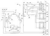
- FIG. 2is a schematic representation of an embodiment of a power conditioner circuit in accordance with the invention, showing how the transformer output is modified and how the power conditioner is connected to a sensitive electrical load;
- FIG. 3is a schematic circuit showing an alternative embodiment of the invention, with suppressors on the transformer input;
- FIG. 4is a schematic representation which combines the features of FIGS. 2 and 3;
- FIG. 5is a further alternative arrangement of the output of the transformer of FIG. 2 in accordance with the invention.
- FIG. 6is another alternative schematic arrangement of the output of the transformer of FIG. 2;
- FIG. 7shows a delta configuration of the output of the windings of the transformer of FIG. 2;
- FIG. 8is an alternative arrangement of the input side of the transformer of FIG. 2;
- FIG. 9shows a further alternative arrangement of the input side of the transformer of FIG. 2;
- FIG. 10is a further schematic arrangement of the output side of the transformer of FIG. 2;
- FIG. 11is an alternative schematic arrangement of the primary windings in a delta configuration
- FIG. 12is another alternative delta configuration schematic arrangement of the primary windings
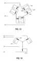
- FIG. 13is a further alternative delta configuration schematic arrangement of the primary windings
- FIG. 14is yet a further alternative schematic arrangement of the primary windings in a wye configuration
- FIG. 15is a further alternative wye configuration of the primary windings
- FIG. 16is a still further alternative wye configuration of the primary windings.
- FIGS. 17A-17Ddepict examples of single-phase transformers employing the present invention.
- FIG. 1Adepicts a cabinet 22 which houses a power conditioner transformer circuit of the invention. Auxiliary circuits may also be contained within the enclosure. Incoming power enters the system through line 27 and output line 26 supplies conditioned power to the equipment or load 31 . Although the power conditioner and the load are shown as separate cabinets, they could both be in a single enclosure. In addition, although FIG. 1A depicts the surge suppression circuitry 23 internal to cabinet 22 , such circuitry 23 could also be provided external to cabinet 22 as depicted in FIG. 1 B.
- FIG. 2illustrates a power conditioning circuit 35 comprised partially of isolation transformer 36 having primary 37 , secondary 38 and iron core 39 .
- the input to primary 37includes input phase conductors 41 , 42 and 43 , which are configured to be connected to an appropriate electrical power source.
- Line 51is the input ground line and is preferably the legal minimum in size in accordance with NEC standards in the present embodiment.
- the transformerwill be equipped with conventional taps 45 , 46 off the primary windings, enabling the transformer to correct for chronic low or high line voltage by connecting the input phase conductors 41 , 42 and 43 to the appropriate respective taps.
- primary segments 80 , 81 and 84 , 85are connected in series.
- primary segments 82 , 83are shown connected in parallel. Either arrangement can work.
- the transformer 36may be a shielded isolation transformer, as indicated by dashed line 61 representing a metal sheet positioned between the primary and secondary windings of the transformer.
- dashed line 61representing a metal sheet positioned between the primary and secondary windings of the transformer.
- a zig-zag transformer, an auto-transformer, tap switchers, variacs, or a non-shielded transformer, among othersare also appropriate for use with the present invention.
- Each output line 62 , 63 and 64 of the power conditionerincludes filter circuits 55 that have at least capacitors connected to the transformer prior to the phase-to-phase neutral bond 60 .
- a resistor 70is connected in series with capacitor 71 .
- the resistor 70may be either a resistor or merely a wire, with the small resistance of the wire providing resistance.
- the filter circuitsalso include inductors.
- shown in finish line 52 of secondary coil 68is inductance 66 . This can be a separate component or the leakage inductance of transformer 36 , or both. Similar inductance 67 is included on the other, or start line 53 of secondary winding 68 .
- resistor 70can be either an actual resistor component or the resistance of the wire that connects the capacitor to the line.
- resistor 72can either be conductors, resistors, or inductors.
- impedance devices 74 and 75can be a bar of conductive material, such as copper. Other highly conductive materials could be employed.
- each resistor/capacitor leg of filter 55By having each resistor/capacitor leg of filter 55 physically connected at spaced locations on each very low impedance device, a very small but measurable impedance will result between the two resistor/capacitor legs. “Very small” in this context is as low as one pico ohm. Filter performance was found to improve as impedances 74 , 75 increased, and were tested to 1 m ⁇ . It is contemplated that filter performance will continue to increase as the impedance increases, but overall system performance will be degraded as the voltage drop through impedances 74 , 75 becomes significant. It is preferred that capacitors 71 and 73 have equal capacitance but that is not a requirement. Those two capacitors may differ in capacitance in any practical manner which still meets the filter requirements.
- the shunt legs of the filter 55 formed of the resistor capacitor series combination which are connected with a low impedance element 74 , 75could be described as having first, second, third and fourth quadrants:
- the first quadrantbeing the connection of the filter circuit 55 connected to one polarity of the secondary winding 68
- the second quadrant of the filter circuit 55being considered the connection which is connected to the opposite polarity of the secondary winding 68
- the third quadrant of the filter circuit 55being considered one polarity of the output of the power conditioning system and being adapted to be connected to the load via line 62
- the fourth quadrant of the filter circuitbeing considered the opposite polarity of the output of the conditioning signal and being adapted to be connected to a load or to a system neutral/ground 60 .
- a similar filter or suppressor structureis connected in the other two transformer secondary output lines and need not be discussed in detail here.
- Ground line 76is provided for a supplemental ground if necessary, and as may be required in some instances for applications that require this ground, such as applications where each article requiring power also requires its own ground or its own grounding stake connection.
- Sensitive electrical load 77is the type of system discussed previously, which may be an X-ray machine, magnetic resonance imaging system or other system requiring high power for short time durations, or systems such as automated test equipment or telecommunications equipment that simply require very clean power.
- Output phase conductors 62 , 63 and 64are relatively large and preferably quite short, which provides higher quality power by minimizing impedance and pickup of radiated noise from other electrical lines or other interference sources.
- Lines 78 and 79are derived neutral and ground respectively.
- the resistor/capacitor filter legs in the output of winding 68may have several different types of components to further optimize performance for a particular type of load.
- these filter legscould incorporate MOVs, SADs, gas discharge tubes, or inductors, among others, either in place of or in addition to the elements shown.
- MOVsMOVs
- SADsgas discharge tubes
- inductorsany additional features will be discussed below.
- each primary winding 80 , 81 , 82 , 83 , 84 and 85 of transformer primary 37includes surge suppression elements 86 , 87 connected between the start and the finish of each winding.
- Windings 80 and 81are connected as shown to make up one phase of the primary of the transformer.
- Each suppression elementshould be rated to accommodate for the maximum voltage of its associated primary coil.
- the magnetic coupling of the windings 80 and 81permit the suppression elements to clamp the input voltage in all primary wiring variations. Additionally, the magnetic coupling of 80 and 81 has the benefit of also forcing more equal energy distribution between suppression devices 86 and 87 than would occur by simply placing two suppression devices in parallel. This leads to less stress and longer life for the suppression devices as well as improved performance.
- Surge suppressors 86 and 87could be metal oxide varistors (MOVs) or silicon avalanche diodes (SADs), among others, which are connected in parallel with one or both primary windings 80 and 81 or any portion of either primary winding.
- MOVsmetal oxide varistors
- SADssilicon avalanche diodes
- a similar suppression structureis connected in parallel with windings 82 , 83 , 84 and 85 and need not be discussed in detail here.
- FIG. 4is a schematic diagram of a preferred embodiment which includes the features of FIGS. 2 and 3 in a single combined structure.
- the combinationprovides for even better power purity because of the combined effects of the surge suppression devices on the input windings and the filter arrangements in the output windings of the transformer.
- This power conditionerprovides cleaner power than any known approach, regardless of the size or rating of the transformer.
- the circuit of FIG. 4attenuates incoming or line-side disturbances with the magnetically coupled surge suppressors, the transformer leakage inductance, the transformer shield, and the L-R-C filters installed, preferably within inches of the output phase conductors.
- the inductance in the L-R-C filtermay be only the transformer leakage inductance, or an additional inductor may be employed.
- the transformeris located outside the room in which the load is positioned. Filters and surge suppressors, when used, have often previously been located between five and 50 feet from the output line.
- the filter suppression systemin the same cabinet as the transformer, represented by enclosure cabinet 22 in FIG. 1 (and thereby all of the system elements, including breakers and surge suppressors, to name a few), the components can each be located with respect to one another at minimum distances for optimum filtering performance. As stated before, preferably those distances are minimized (as close to zero as practically possible).
- Output, or load generated disturbancesare also attenuated by the low power conditioner impedance and output filters. This helps decouple various connected loads.
- the low impedance neutral-ground bondeliminates incoming ground noise and attenuates load generated common mode noise.
- FIG. 5has added features which may be incorporated into the circuits of FIG. 2 or FIG. 4 .
- This embodimentadds additional R-C filter circuitry in cascade fashion to the transformer output windings to make the output scalable as may be required to optimize filter performance and cost. While two dual leg resistor-capacitor combinations are shown, additional filter modules could be added in the output windings of the transformer to improve performance further, as required.
- the structures and functionsare the same as previously described.
- FIG. 6Another set of features which may be incorporated into the invention of FIGS. 2, 4 or 5 is shown in FIG. 6 .
- Connected across each resistor 70 , 72 in filter 56is anti-parallel diode combination 91 , 92 . These serve to further enhance the surge suppression and filtering effectiveness of the transformer output winding filter circuitry.
- FIGS. 8 and 9show the example of each primary winding 101 being a single segment with a suppressor device 102 connected across it.
- the wye configuration of FIG. 9shows split primaries as discussed previously, each primary winding segment having a suppression device 105 , 106 connected across it. Building neutral is represented by line 108 in each of these two figures.
- a transformer output sideis shown in FIG. 10, with the start of each secondary coil being connected to the load through the R-C filter. In this case the start 107 of each secondary coil is connected directly to system ground 60 . This is an alternative arrangement of the secondary coil connections.
- FIG. 11An alternative arrangement of the primary windings and their connections to the input power lines is shown in FIG. 11 .
- input phase conductors 41 , 42 and 43connect to the winding taps.
- Suppressor elements 111 , 112 and 113are connected across the ends of primary windings 114 , 115 and 116 , respectively. This is a delta configuration.
- FIG. 12Another alternative arrangement of the primary windings in a delta configuration is shown in FIG. 12 .
- the windingsare dual coils 121 , 122 , each with suppressor elements 123 and 124 , respectively, connected across the coil segment ends.
- the primary coilsare wired in series and, as in FIG. 11, the input voltage 41 , 42 , 43 is applied to the coil taps. Only one coil pair is specifically described but the others are connected the same way.
- FIG. 13Still another arrangement of the input voltage and the primary coils is shown in FIG. 13 .
- Input line 41is connected to the taps of coils 126 , 127 , each of which has a suppressor element 128 , 129 connected across the coil ends.
- the other two primary dual coilsare similarly connected.
- the segments of each split primaryare connected in parallel. This is also a delta configuration.
- FIG. 14shows a wye configuration of the primary windings.
- Suppressor 132is connected across the ends of winding 131 , while input voltage 42 is connected to a tap of the winding. The same is true of the other windings shown.
- Neutralis designated by reference numeral 51 .
- FIG. 15Another wye configuration is shown in FIG. 15 .
- Suppressor elements 133 , 134are connected across the ends of coil segments 135 , 136 .
- Neutral line 51is connected to common node 137 .
- the primary coils in each split pairare connected in series.
- FIG. 16shows still another wye configuration of the primary windings. This time the split primary segments are connected in parallel.
- the input voltage line 41is connected to the taps of coil segments 141 , 142 , each of which has a suppressor element 143 , 144 across the ends.
- Neutral 51is connected the same as before.
- FIG. 17Adepicts a single-phase transformer 200 incorporating both the suppressor and filter features of the present invention.
- the transformer 200has a primary 202 , a secondary 204 , a suppressor element 206 and the filter 55 .
- FIG. 17Aalso depicts a load 210 coupled to the output of the filter 55 .
- additional output filtercan be cascaded to add additional protection.
- the suppressor element 206 and the filter 55are of any types described above.
- FIG. 17Bsimilarly depicts a single phase transformer 220 having a primary 222 and a secondary 224 .
- the primary and secondaryeach have first and second coils connected in a conventional fashion.
- the coilseach have a suppressor element 206 a , 206 b coupled across the start and finish of each of the coils, regardless of whether the source is coupled to a tap of the transformer.
- the secondary coilseach has a filter element 55 a , 55 b coupled to each coil at its output start and finish leads with the common neutral 226 connected at the output of the filters 55 a , 55 b , similar to FIG. 17 A.
- FIG. 17Balso depicts a load 228 .
- FIG. 17Cdepicts a single-phase transformer with no suppressor
- FIG. 17Ddepicts a single phase transformer with no filter.
- the inventioncan work equally well in a system with any number of phases.
Landscapes
- Engineering & Computer Science (AREA)
- Power Engineering (AREA)
- Filters And Equalizers (AREA)
- Emergency Protection Circuit Devices (AREA)
Abstract
Description
Claims (50)
Priority Applications (1)
| Application Number | Priority Date | Filing Date | Title |
|---|---|---|---|
| US09/632,547US6624997B1 (en) | 2000-08-04 | 2000-08-04 | Electrical power conditioner |
Applications Claiming Priority (1)
| Application Number | Priority Date | Filing Date | Title |
|---|---|---|---|
| US09/632,547US6624997B1 (en) | 2000-08-04 | 2000-08-04 | Electrical power conditioner |
Publications (1)
| Publication Number | Publication Date |
|---|---|
| US6624997B1true US6624997B1 (en) | 2003-09-23 |
Family
ID=28042294
Family Applications (1)
| Application Number | Title | Priority Date | Filing Date |
|---|---|---|---|
| US09/632,547Expired - LifetimeUS6624997B1 (en) | 2000-08-04 | 2000-08-04 | Electrical power conditioner |
Country Status (1)
| Country | Link |
|---|---|
| US (1) | US6624997B1 (en) |
Cited By (14)
| Publication number | Priority date | Publication date | Assignee | Title |
|---|---|---|---|---|
| US7233086B2 (en) | 2004-01-07 | 2007-06-19 | Belkin International, Inc. | Power line conditioner |
| US20070159723A1 (en)* | 2006-01-10 | 2007-07-12 | Peter Dang | Assembly, apparatus and method for fabricating a structural element of a hard disk drive air bearing |
| WO2007117449A3 (en)* | 2006-03-31 | 2008-04-24 | Leveler Llc | Polyphase power conditioning circuits |
| US20110080693A1 (en)* | 2009-10-02 | 2011-04-07 | Delta Electronics, Inc. | Power distribution unit for receiving diversified three-phase power or single-phase power |
| US20140340807A1 (en)* | 2011-12-12 | 2014-11-20 | Waikatolink Limited | Power and telecommunications surge protection apparatus |
| EP2230741A3 (en)* | 2009-03-16 | 2015-01-07 | Leveler LLC | Power conditioning circuit utilizing high oersted rating inductors |
| US20150188509A1 (en)* | 2013-12-30 | 2015-07-02 | Det International Holding Limited | Choke and emi filter with the same |
| US20160149396A1 (en)* | 2014-11-21 | 2016-05-26 | Abb Ab | System For Protection Of Dry Type Transformers |
| US20160170431A1 (en)* | 2013-07-26 | 2016-06-16 | Siemens Aktiengesellschaft | Internal power supply of a device |
| CN106357094A (en)* | 2016-10-09 | 2017-01-25 | 上海联影医疗科技有限公司 | System and method for controlling magnetic resonance power source |
| US20180233265A1 (en)* | 2017-02-16 | 2018-08-16 | Fanuc Corporation | Reactor having iron core unit and coils, motor driver, power conditioner and machine |
| CN111130599A (en)* | 2020-01-19 | 2020-05-08 | 成都长城开发科技有限公司 | Three-phase coupling circuit for carrier communication of power grid system |
| US10751231B2 (en) | 2017-06-01 | 2020-08-25 | Lifeline Mobile, Inc. | System for powering medical imaging systems |
| US20230011472A1 (en)* | 2020-07-01 | 2023-01-12 | Hitachi Energy Switzerland Ag | Transformer arrangement and method for electrically connecting and disconnecting a transformer |
Citations (10)
| Publication number | Priority date | Publication date | Assignee | Title |
|---|---|---|---|---|
| US3711760A (en)* | 1971-06-30 | 1973-01-16 | Westinghouse Electric Corp | Rectifier-transformer system |
| US3882369A (en)* | 1973-11-28 | 1975-05-06 | Gen Electric | Control of cycloconverter systems having a parallel resonant commutation circuit |
| US4095163A (en)* | 1976-06-01 | 1978-06-13 | Control Concepts Corporation | Transient voltage suppression circuit |
| US4156838A (en) | 1978-06-12 | 1979-05-29 | Control Concepts Corporation | Active filter circuit for transient suppression |
| US4771356A (en)* | 1987-02-02 | 1988-09-13 | The Toro Company | Method and apparatus for accommodating power disturbances |
| US4802055A (en) | 1987-10-26 | 1989-01-31 | Joseph L. Brooks Manufacturing Corp. | Transient voltage surge suppressor |
| US5012382A (en)* | 1990-06-14 | 1991-04-30 | Teal Electronics Corporation | Low impedance power conditioner apparatus and method |
| US5038245A (en) | 1989-09-15 | 1991-08-06 | Lennart Gronskog | Method and apparatus for suppressing electrical transients |
| US5388021A (en)* | 1992-09-18 | 1995-02-07 | The United States Of America As Represented By The Secretary Of The Navy | Voltage surge suppression power circuits |
| US5535087A (en)* | 1994-01-14 | 1996-07-09 | Power Quality Engineering, Inc. | Circuit for reducing effects of transient events on electronic equipment |
- 2000
- 2000-08-04USUS09/632,547patent/US6624997B1/ennot_activeExpired - Lifetime
Patent Citations (10)
| Publication number | Priority date | Publication date | Assignee | Title |
|---|---|---|---|---|
| US3711760A (en)* | 1971-06-30 | 1973-01-16 | Westinghouse Electric Corp | Rectifier-transformer system |
| US3882369A (en)* | 1973-11-28 | 1975-05-06 | Gen Electric | Control of cycloconverter systems having a parallel resonant commutation circuit |
| US4095163A (en)* | 1976-06-01 | 1978-06-13 | Control Concepts Corporation | Transient voltage suppression circuit |
| US4156838A (en) | 1978-06-12 | 1979-05-29 | Control Concepts Corporation | Active filter circuit for transient suppression |
| US4771356A (en)* | 1987-02-02 | 1988-09-13 | The Toro Company | Method and apparatus for accommodating power disturbances |
| US4802055A (en) | 1987-10-26 | 1989-01-31 | Joseph L. Brooks Manufacturing Corp. | Transient voltage surge suppressor |
| US5038245A (en) | 1989-09-15 | 1991-08-06 | Lennart Gronskog | Method and apparatus for suppressing electrical transients |
| US5012382A (en)* | 1990-06-14 | 1991-04-30 | Teal Electronics Corporation | Low impedance power conditioner apparatus and method |
| US5388021A (en)* | 1992-09-18 | 1995-02-07 | The United States Of America As Represented By The Secretary Of The Navy | Voltage surge suppression power circuits |
| US5535087A (en)* | 1994-01-14 | 1996-07-09 | Power Quality Engineering, Inc. | Circuit for reducing effects of transient events on electronic equipment |
Non-Patent Citations (3)
| Title |
|---|
| Donald G. Fink, John M. Carrol. Standard Handbook for Electrical Engineers; May 1974, 10<th >Edition, McGrow-Hill Co.** |
| Donald G. Fink, John M. Carrol. Standard Handbook for Electrical Engineers; May 1974, 10th Edition, McGrow-Hill Co.* |
| R. Taylor. Application Note AN34. Crystal Semiconductor Company; Sep. 1994.* |
Cited By (27)
| Publication number | Priority date | Publication date | Assignee | Title |
|---|---|---|---|---|
| US7233086B2 (en) | 2004-01-07 | 2007-06-19 | Belkin International, Inc. | Power line conditioner |
| US20070267919A1 (en)* | 2004-01-07 | 2007-11-22 | Belkin International, Inc. | Power line conditioner |
| US7436087B2 (en) | 2004-01-07 | 2008-10-14 | Belkin International, Inc. | Power line conditioner |
| US20070159723A1 (en)* | 2006-01-10 | 2007-07-12 | Peter Dang | Assembly, apparatus and method for fabricating a structural element of a hard disk drive air bearing |
| EP2005551A4 (en)* | 2006-03-31 | 2014-04-30 | Leveler Llc | Polyphase power conditioning circuits |
| WO2007117449A3 (en)* | 2006-03-31 | 2008-04-24 | Leveler Llc | Polyphase power conditioning circuits |
| AU2007235535B2 (en)* | 2006-03-31 | 2012-03-15 | Leveler Llc | Polyphase power conditioning circuits |
| EP2230741A3 (en)* | 2009-03-16 | 2015-01-07 | Leveler LLC | Power conditioning circuit utilizing high oersted rating inductors |
| US8659881B2 (en)* | 2009-10-02 | 2014-02-25 | Delta Electronics, Inc. | Power distribution unit for receiving diversified three-phase power or single-phase power |
| US20110080693A1 (en)* | 2009-10-02 | 2011-04-07 | Delta Electronics, Inc. | Power distribution unit for receiving diversified three-phase power or single-phase power |
| US20140340807A1 (en)* | 2011-12-12 | 2014-11-20 | Waikatolink Limited | Power and telecommunications surge protection apparatus |
| US9466977B2 (en)* | 2011-12-12 | 2016-10-11 | Waikatolink Limited | Power and telecommunications surge protection apparatus |
| US9600012B2 (en)* | 2013-07-26 | 2017-03-21 | Siemens Aktiengesellschaft | Internal power supply of a device |
| US20160170431A1 (en)* | 2013-07-26 | 2016-06-16 | Siemens Aktiengesellschaft | Internal power supply of a device |
| US20150188509A1 (en)* | 2013-12-30 | 2015-07-02 | Det International Holding Limited | Choke and emi filter with the same |
| US9537463B2 (en)* | 2013-12-30 | 2017-01-03 | Det International Holding Limited | Choke and EMI filter with the same |
| US20160149396A1 (en)* | 2014-11-21 | 2016-05-26 | Abb Ab | System For Protection Of Dry Type Transformers |
| KR20170086615A (en)* | 2014-11-21 | 2017-07-26 | 에이비비 슈바이쯔 아게 | System for protection of dry type transformers |
| US9882373B2 (en)* | 2014-11-21 | 2018-01-30 | Abb Schweiz Ag | System for protection of dry type transformers |
| CN106357094A (en)* | 2016-10-09 | 2017-01-25 | 上海联影医疗科技有限公司 | System and method for controlling magnetic resonance power source |
| CN106357094B (en)* | 2016-10-09 | 2017-11-07 | 上海联影医疗科技有限公司 | A kind of magnetic resonance power control system and method |
| US20180233265A1 (en)* | 2017-02-16 | 2018-08-16 | Fanuc Corporation | Reactor having iron core unit and coils, motor driver, power conditioner and machine |
| US10751231B2 (en) | 2017-06-01 | 2020-08-25 | Lifeline Mobile, Inc. | System for powering medical imaging systems |
| US11266552B2 (en) | 2017-06-01 | 2022-03-08 | Lifeline Mobile, Inc. | System for powering medical imaging systems |
| US12290479B2 (en) | 2017-06-01 | 2025-05-06 | Lifeline Mobile, Inc. | System for powering medical imaging systems |
| CN111130599A (en)* | 2020-01-19 | 2020-05-08 | 成都长城开发科技有限公司 | Three-phase coupling circuit for carrier communication of power grid system |
| US20230011472A1 (en)* | 2020-07-01 | 2023-01-12 | Hitachi Energy Switzerland Ag | Transformer arrangement and method for electrically connecting and disconnecting a transformer |
Similar Documents
| Publication | Publication Date | Title |
|---|---|---|
| US5640314A (en) | Symmetrical power system | |
| US6624997B1 (en) | Electrical power conditioner | |
| EP0870353B1 (en) | Isolated electrical power supply | |
| US7944326B2 (en) | EMC filter | |
| US5619079A (en) | EMI line filter | |
| US5416458A (en) | Power distribution transformer for non-linear loads | |
| CA2157307C (en) | Zero-sequence current suppressor | |
| JP2008047517A (en) | Connection apparatus | |
| US11289260B2 (en) | Low EMI transformator and low EMI electric cable | |
| US7199699B1 (en) | Facilitating communication with power line communication devices | |
| JP4017343B2 (en) | Power adjustment circuit | |
| US4677401A (en) | Noise filter for three-phase four-wire system | |
| KR101717561B1 (en) | Neutral line current remover | |
| CN116742599A (en) | Multiphase AC power contact arc suppressor | |
| US6278266B1 (en) | Symmetrical power generator and method of use | |
| US6844794B2 (en) | Harmonic mitigating filter | |
| US5814901A (en) | Harmonic blocking at source transformer | |
| EP0533822B1 (en) | Low impedance power conditioner apparatus | |
| KR101487142B1 (en) | Apparatus and method for removing neutral line current | |
| JPH06261442A (en) | Leakage current prevention circuit | |
| JP3469056B2 (en) | Electrical equipment | |
| CN220065403U (en) | Transformer and power supply equipment | |
| US20040004799A1 (en) | Non-ferrous surge biasing coil having multiple pairs of coils positioned at angles to one another | |
| Buzdugan | A Reduction Technique of Electromagnetic Noise Generated by Three-Phase Power Electronic Converters | |
| CA2240414C (en) | Isolated electrical power supply |
Legal Events
| Date | Code | Title | Description |
|---|---|---|---|
| AS | Assignment | Owner name:TEAL ELECTRONICS CORPORATION, CALIFORNIA Free format text:ASSIGNMENT OF ASSIGNORS INTEREST;ASSIGNORS:LLANOS, REYNALDO P.;SOTO, VICTOR;REDDING, RANDALL J.;REEL/FRAME:011034/0534;SIGNING DATES FROM 20000728 TO 20000801 | |
| AS | Assignment | Owner name:MELLON BANK, N.A., PENNSYLVANIA Free format text:SECURITY AGREEMENT;ASSIGNORS:SL INDUSTRIES, INC.;CEDAR CORPORATION;CONDOR D.C. POWER SUPPLIES, INC.;AND OTHERS;REEL/FRAME:012312/0902 Effective date:20011213 | |
| AS | Assignment | Owner name:TEAL ELECTRONICS CORPORATION, NEW JERSEY Free format text:TERMINATION OF SECURITY INTEREST;ASSIGNOR:MELLON BANK, N.A.;REEL/FRAME:012698/0793 Effective date:20020226 | |
| AS | Assignment | Owner name:GE CAPITAL CFE, INC., ILLINOIS Free format text:ASSIGNMENT OF ASSIGNORS INTEREST;ASSIGNOR:TEAL ELECTRONICS CORPORATION;REEL/FRAME:012754/0482 Effective date:20020226 | |
| AS | Assignment | Owner name:SL DELAWARE, INC., DELAWARE Free format text:TERMINATION OF SECURITY INTEREST;ASSIGNOR:GE CAPITAL CFE, INC.;REEL/FRAME:013634/0721 Effective date:20021220 Owner name:SL INDUSTRIES, INC., NEW JERSEY Free format text:TERMINATION OF SECURITY INTEREST;ASSIGNOR:GE CAPITAL CFE, INC.;REEL/FRAME:013634/0721 Effective date:20021220 | |
| STCF | Information on status: patent grant | Free format text:PATENTED CASE | |
| AS | Assignment | Owner name:BANK OF AMERICA, N.A., AS AGENT, PENNSYLVANIA Free format text:ASSIGNMENT OF ASSIGNORS INTEREST;ASSIGNORS:CONDOR DC POWER SUPPLIES, INC.;TEAL ELECTRONICS CORPORATION;RFL ELECTRONICS CORPORATION;AND OTHERS;REEL/FRAME:016945/0281 Effective date:20050803 | |
| AS | Assignment | Owner name:SL DELAWARE HOLDINGS, INC., NEW JERSEY Free format text:ASSIGNMENT OF ASSIGNORS INTEREST;ASSIGNOR:LASALLE BUSINESS CREDIT, LLC;REEL/FRAME:016987/0824 Effective date:20050803 Owner name:SL INDUSTRIES, INC., NEW JERSEY Free format text:ASSIGNMENT OF ASSIGNORS INTEREST;ASSIGNOR:LASALLE BUSINESS CREDIT, LLC;REEL/FRAME:016987/0824 Effective date:20050803 Owner name:CONDOR D.C. POWER SUPPLIES, INC., NEW JERSEY Free format text:ASSIGNMENT OF ASSIGNORS INTEREST;ASSIGNOR:LASALLE BUSINESS CREDIT, LLC;REEL/FRAME:016987/0824 Effective date:20050803 Owner name:SL DELAWARE, INC., NEW JERSEY Free format text:ASSIGNMENT OF ASSIGNORS INTEREST;ASSIGNOR:LASALLE BUSINESS CREDIT, LLC;REEL/FRAME:016987/0824 Effective date:20050803 Owner name:RFL ELECTRONICS, INC., NEW JERSEY Free format text:ASSIGNMENT OF ASSIGNORS INTEREST;ASSIGNOR:LASALLE BUSINESS CREDIT, LLC;REEL/FRAME:016987/0824 Effective date:20050803 Owner name:SLW HOLDINGS, INC., NEW JERSEY Free format text:ASSIGNMENT OF ASSIGNORS INTEREST;ASSIGNOR:LASALLE BUSINESS CREDIT, LLC;REEL/FRAME:016987/0824 Effective date:20050803 Owner name:CEDAR CORPORATION, NEW JERSEY Free format text:ASSIGNMENT OF ASSIGNORS INTEREST;ASSIGNOR:LASALLE BUSINESS CREDIT, LLC;REEL/FRAME:016987/0824 Effective date:20050803 Owner name:WABER POWER, LTD., NEW JERSEY Free format text:ASSIGNMENT OF ASSIGNORS INTEREST;ASSIGNOR:LASALLE BUSINESS CREDIT, LLC;REEL/FRAME:016987/0824 Effective date:20050803 Owner name:CONDOR HOLDINGS, INC., NEW JERSEY Free format text:ASSIGNMENT OF ASSIGNORS INTEREST;ASSIGNOR:LASALLE BUSINESS CREDIT, LLC;REEL/FRAME:016987/0824 Effective date:20050803 Owner name:TEAL ELECTRONICS CORPORATION, NEW JERSEY Free format text:ASSIGNMENT OF ASSIGNORS INTEREST;ASSIGNOR:LASALLE BUSINESS CREDIT, LLC;REEL/FRAME:016987/0824 Effective date:20050803 Owner name:SL AUBURN, INC., NEW JERSEY Free format text:ASSIGNMENT OF ASSIGNORS INTEREST;ASSIGNOR:LASALLE BUSINESS CREDIT, LLC;REEL/FRAME:016987/0824 Effective date:20050803 Owner name:SL SURFACE TECHNOLOGIES, INC., NEW JERSEY Free format text:ASSIGNMENT OF ASSIGNORS INTEREST;ASSIGNOR:LASALLE BUSINESS CREDIT, LLC;REEL/FRAME:016987/0824 Effective date:20050803 Owner name:SL MONTEVIDEO TECHNOLOGY, INC., NEW JERSEY Free format text:ASSIGNMENT OF ASSIGNORS INTEREST;ASSIGNOR:LASALLE BUSINESS CREDIT, LLC;REEL/FRAME:016987/0824 Effective date:20050803 | |
| FPAY | Fee payment | Year of fee payment:4 | |
| AS | Assignment | Owner name:BANK OF AMERICA, N.A., PENNSYLVANIA Free format text:SECURITY AGREEMENT;ASSIGNORS:SL INDUSTRIES, INC.;SL DELAWARE, INC.;SL DELAWARE HOLDINGS, INC.;AND OTHERS;REEL/FRAME:021731/0146 Effective date:20081023 | |
| FPAY | Fee payment | Year of fee payment:8 | |
| AS | Assignment | Owner name:SL INDUSTRIES, INC., NEW JERSEY Free format text:RELEASE BY SECURED PARTY;ASSIGNOR:BANK OF AMERICA, N.A.;REEL/FRAME:028795/0546 Effective date:20120809 Owner name:SL DELAWARE, INC., NEW JERSEY Free format text:RELEASE BY SECURED PARTY;ASSIGNOR:BANK OF AMERICA, N.A.;REEL/FRAME:028795/0546 Effective date:20120809 Owner name:SL DELAWARE HOLDINGS, INC., NEW JERSEY Free format text:RELEASE BY SECURED PARTY;ASSIGNOR:BANK OF AMERICA, N.A.;REEL/FRAME:028795/0546 Effective date:20120809 Owner name:MTE CORPORATION, NEW JERSEY Free format text:RELEASE BY SECURED PARTY;ASSIGNOR:BANK OF AMERICA, N.A.;REEL/FRAME:028795/0546 Effective date:20120809 Owner name:RFL ELECTRONICS INC., NEW JERSEY Free format text:RELEASE BY SECURED PARTY;ASSIGNOR:BANK OF AMERICA, N.A.;REEL/FRAME:028795/0546 Effective date:20120809 Owner name:SL MONTEVIDEO TECHNOLOGY, INC., NEW JERSEY Free format text:RELEASE BY SECURED PARTY;ASSIGNOR:BANK OF AMERICA, N.A.;REEL/FRAME:028795/0546 Effective date:20120809 Owner name:CEDAR CORPORATION, NEW JERSEY Free format text:RELEASE BY SECURED PARTY;ASSIGNOR:BANK OF AMERICA, N.A.;REEL/FRAME:028795/0546 Effective date:20120809 Owner name:TEAL ELECTRONICS CORPORATION, NEW JERSEY Free format text:RELEASE BY SECURED PARTY;ASSIGNOR:BANK OF AMERICA, N.A.;REEL/FRAME:028795/0546 Effective date:20120809 Owner name:MEX HOLDINGS LLC, NEW JERSEY Free format text:RELEASE BY SECURED PARTY;ASSIGNOR:BANK OF AMERICA, N.A.;REEL/FRAME:028795/0546 Effective date:20120809 Owner name:SL POWER ELECTRONIC CORPORATION, NEW JERSEY Free format text:RELEASE BY SECURED PARTY;ASSIGNOR:BANK OF AMERICA, N.A.;REEL/FRAME:028795/0546 Effective date:20120809 Owner name:SLGC HOLDINGS, INC., NEW JERSEY Free format text:RELEASE BY SECURED PARTY;ASSIGNOR:BANK OF AMERICA, N.A.;REEL/FRAME:028795/0546 Effective date:20120809 Owner name:SLW HOLDINGS, INC., NEW JERSEY Free format text:RELEASE BY SECURED PARTY;ASSIGNOR:BANK OF AMERICA, N.A.;REEL/FRAME:028795/0546 Effective date:20120809 Owner name:SL AUBURN, INC., NEW JERSEY Free format text:RELEASE BY SECURED PARTY;ASSIGNOR:BANK OF AMERICA, N.A.;REEL/FRAME:028795/0546 Effective date:20120809 Owner name:SL SURFACE TECHNOLOGIES, INC., NEW JERSEY Free format text:RELEASE BY SECURED PARTY;ASSIGNOR:BANK OF AMERICA, N.A.;REEL/FRAME:028795/0546 Effective date:20120809 Owner name:CONDOR D.C. POWER SUPPLIES, INC., NEW JERSEY Free format text:RELEASE BY SECURED PARTY;ASSIGNOR:BANK OF AMERICA, N.A.;REEL/FRAME:028795/0619 Effective date:20120809 Owner name:PNC BANK, NATIONAL ASSOCIATION, PENNSYLVANIA Free format text:SECURITY AGREEMENT;ASSIGNORS:SL INDUSTRIES, INC.;MTE CORPORATION;SL DELAWARE HOLDINGS, INC.;AND OTHERS;REEL/FRAME:028802/0081 Effective date:20120809 | |
| FPAY | Fee payment | Year of fee payment:12 | |
| AS | Assignment | Owner name:MTE CORPORATION, WISCONSIN Free format text:ASSIGNMENT OF ASSIGNORS INTEREST;ASSIGNOR:TEAL ELECTRONICS CORPORATION;REEL/FRAME:039698/0816 Effective date:20160909 | |
| AS | Assignment | Owner name:MTE CORPORATION, WISCONSIN Free format text:MERGER;ASSIGNOR:TEAL ELECTRONICS CORPORATION;REEL/FRAME:039794/0797 Effective date:20160603 | |
| AS | Assignment | Owner name:PNC BANK, NATIONAL ASSOCIATION, PENNSYLVANIA Free format text:SECURITY INTEREST;ASSIGNORS:BLACK HAWK ENERGY SERVICES LTD.;HANDY & HARMAN;HANDYTUBE CORPORATION;AND OTHERS;REEL/FRAME:044678/0939 Effective date:20171114 |