US6624916B1 - Signalling system - Google Patents
Signalling systemDownload PDFInfo
- Publication number
- US6624916B1 US6624916B1US09/367,223US36722399AUS6624916B1US 6624916 B1US6624916 B1US 6624916B1US 36722399 AUS36722399 AUS 36722399AUS 6624916 B1US6624916 B1US 6624916B1
- Authority
- US
- United States
- Prior art keywords
- reflector
- modulator
- signalling device
- signalling
- operable
- Prior art date
- Legal status (The legal status is an assumption and is not a legal conclusion. Google has not performed a legal analysis and makes no representation as to the accuracy of the status listed.)
- Expired - Fee Related
Links
Images


Classifications
- H—ELECTRICITY
- H04—ELECTRIC COMMUNICATION TECHNIQUE
- H04B—TRANSMISSION
- H04B10/00—Transmission systems employing electromagnetic waves other than radio-waves, e.g. infrared, visible or ultraviolet light, or employing corpuscular radiation, e.g. quantum communication
- H04B10/11—Arrangements specific to free-space transmission, i.e. transmission through air or vacuum
- H04B10/112—Line-of-sight transmission over an extended range
- H04B10/1123—Bidirectional transmission
- H04B10/1125—Bidirectional transmission using a single common optical path
- H—ELECTRICITY
- H04—ELECTRIC COMMUNICATION TECHNIQUE
- H04B—TRANSMISSION
- H04B10/00—Transmission systems employing electromagnetic waves other than radio-waves, e.g. infrared, visible or ultraviolet light, or employing corpuscular radiation, e.g. quantum communication
- H04B10/11—Arrangements specific to free-space transmission, i.e. transmission through air or vacuum
- H04B10/114—Indoor or close-range type systems
- H04B10/1149—Arrangements for indoor wireless networking of information
Definitions
- the present inventionrelates to a signalling system.
- One aspect of the present inventionrelates to a free space point to multipoint signalling method and apparatus.
- Another aspect of the inventionrelates to a retro-reflector for use in a signalling system.
- the present inventionrelates to a multipoint to point signalling system.
- Another type of known point to multipoint communications systememploys cables (optical and/or electrical) and taps/junctions through which communications from a transmitter are passed to multiple receivers.
- cablesoptical and/or electrical
- taps/junctionsthrough which communications from a transmitter are passed to multiple receivers.
- these cable systemscan be expensive, due to the cost of the cable itself and its installation, and is not suitable in some situations.
- it may be practical to install cable along most streetsit may not be practical to install the cable from the street into every home and office along the side of the street. Cable systems are also not practical in temporary systems where a short term communications link is required.
- Another type of known point to multipoint communication systemis an optical broadcast system, in which the messages are broadcast as optical signals from an optical transmitter to a plurality of remote optical receivers.
- an optical broadcast systemsuffers from the disadvantage that a large amount of the transmitted power is wasted due to the broadcasting of the signals into areas where there are no receivers.
- present systemscan only broadcast over short distances of about a few metres.
- the present inventionprovides an alternative point to multipoint signalling system.
- the present inventionprovides a point to multipoint signalling system, comprising a first signalling device and a plurality of second signalling devices
- the first signalling devicecomprises: means for receiving signals transmitted from the plurality of second signalling devices, means for modulating the received signals with respective modulation data for the second signalling devices and means for reflecting the modulated signals back to the respective second signalling devices
- each second signalling devicecomprises: means for generating a signal, means for transmitting the generated signal to said first signalling device, means for receiving the modulated signal which is reflected back from said first signalling device, and means for retrieving the modulation data from the reflected signal.
- the present inventionalso relates to a retro-reflector for use in a signalling system.
- Optical retro-ref lectorsare commonly used in a wide variety of applications from precision metrology to “cats-eye” road markers.
- the main function of the retro-reflectoris to reflect incident light back towards the source.
- Plane mirrorsare only effective as optical retro-reflecting elements when they are carefully aligned with the source, so that the reflective surface is orthogonal to the direction of travel of the light emitted from the source.
- Corner cube reflectorstypically comprise an arrangement of three mutually perpendicular mirrors. Alternatively, they can be constructed from a glass prism with three mutually perpendicular reflecting surfaces formed by the faces of the prism. Light incident on such a corner cube reflector is reflected from all three surfaces and travels back towards the source parallel to its original path. Typically these corner cube reflectors have acceptance angles (i.e. a field of view) of +/ ⁇ 30°, thereby eliminating the need for precise angular alignment with the source.
- spherical retro-reflectorsThere are several different forms of spherical retro-reflectors. The most common comprises a relatively high reflective index sphere which focuses the incident light on the rear surface of the sphere (which can be coated with a reflective coating) where it is reflected back along its original path. This is the basis of the “cats-eye” type reflectors commonly used for road markings. Other types of spherical retro-reflectors comprise of one or more concentric spheres of differing refractive index or reflectivity, with the reflection occurring at the surface of the concentric spheres.
- a second aspect of the present inventionaims to provide an alternative type of retro-reflector.
- the present inventionprovides a retro-reflector comprising: a focusing member, having first and second focal planes, for focusing signals received from a source, a stop member, located substantially at said first focal plane, for blocking part of the received signals from said focusing member and a reflecting member, located substantially at said second focal plane, for reflecting said signal back to said source.
- the second aspect of the inventionalso provides a retro-reflector comprising a telecentric lens for receiving and focusing light from a light source and a reflecting means located substantially at the focal plane of said telecentric lens for reflecting said light back to said light source.
- a third aspect of the present inventionaims to provide an alternative type of multipoint to point signalling system.
- the present inventionprovides a multipoint to point signalling system, comprising a first signalling device and a plurality of second signalling devices located at preselected locations with respect to said first signalling device, wherein each second signalling device comprises: at least one sensor input terminal operable to receive a signal from a sensor and a light source operable to generate a light beam in dependence upon said sensor signal for transmission to said first signalling device and wherein said first signalling device comprises: a plurality of light detectors for detecting light transmitted from the plurality of second signalling devices and means for focusing the light transmitted from each second signalling device onto a respective light detector.
- FIG. 1is a schematic block diagram of a video data point to multipoint communication system
- FIG. 2is a schematic block diagram of a local distribution node and a user terminal forming part of the video and data communication system shown in FIG. 1;
- FIG. 3is a schematic diagram of a retro-reflecting modulator unit employed in the local distribution node shown in FIG. 2;
- FIG. 4is a schematic diagram of a pixellated modulator forming part of the retro-reflecting modulator unit shown in FIG. 3;
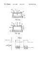
- FIG. 5 ais a cross sectional view of one modulator of the pixellated modulator shown in FIG. 4 in a first operational mode when no DC bias is applied to electrodes thereof;
- FIG. 5 bis a cross sectional view of one modulator of the pixellated modulator shown in FIG. 4 in a second operational mode when a bias voltage is applied to the electrodes;
- FIG. 6is a signal diagram which illustrates the way in which light incident on one of the modulators shown in FIG. 4 is modulated in dependence upon the bias voltage applied to the pixel electrodes;
- FIG. 7is a schematic diagram of a local area network employed in an office environment which has two optical point to multipoint signalling systems
- FIG. 8is a schematic diagram of a data distribution system
- FIG. 9is a schematic diagram of a local distribution node and a user terminal forming part of the data distribution system shown in FIG. 8;
- FIG. 10is a schematic illustration of a retro-reflecting modulator employed in the local distribution node shown in FIG. 9;
- FIG. 11schematically illustrates an array of liquid crystal modulators forming part of the retro-reflecting modulator shown in FIG. 10;
- FIG. 12shows a cross section of a portion of one of the liquid crystal modulators shown in FIG. 11;
- FIG. 13 aillustrates the operation of a liquid crystal modulator with no bias potential applied to electrodes thereof
- FIG. 13 billustrates the operation of a liquid crystal modulator with an alternating bias potential applied to the electrodes thereof
- FIG. 14 ais a schematic diagram of an alternative retro-reflecting modulator which may be employed a point to multipoint communication system
- FIG. 14 bis a perspective view of the retro-reflecting modulator shown in FIG. 14 a;
- FIG. 14 cis a cross sectional view of a further alternative retro-reflecting modulator which can be used in a point to multipoint signalling system;
- FIG. 15 aillustrates an alternative type of modulator which can be used in a retro-reflector in a point to multipoint signalling system
- FIG. 15 bis a signal diagram which illustrates a first mode of,operation of the modulator shown in FIG. 15 a;
- FIG. 15 cis a signal diagram illustrating a second mode of operation of the modulator shown in FIG. 15 a;
- FIG. 16 ais a schematic diagram of a piezoelectric modulator which can perform phase and frequency modulation to light incident thereon;
- FIG. 16 bis a signal diagram illustrating the way in which phase and frequency modulation is achieved by the modulator shown in FIG. 16 a;
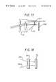
- FIG. 17is a schematic diagram of a retro-reflector and modem unit which uses a beam splitter to split incident laser beams onto a separate modulator array and demodulator array;
- FIG. 18is a schematic diagram which illustrates the way in which a micro-lens can be placed in front of a modulator cell so as to increase the collimation of light into the modulator cell;
- FIG. 19is a block diagram of a multipoint to point monitoring system.
- FIG. 20is a block diagram which illustrates a local monitoring node and a number of sensor terminals forming part of the monitoring system shown in FIG. 19 .
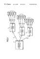
- FIG. 1schematically illustrates a video broadcast system for supplying video signals, for a plurality of television channels, to a plurality of remote users.
- the systemcomprises a central distribution system 1 which transmits optical video signals to a plurality of local distribution nodes 3 via a bundle of optical fibres 5 .
- the local distribution nodes 3are arranged to receive the optical video signals transmitted from the central distribution system 1 and to transmit relevant parts of the video signals to respective user terminals 7 (which are spatially fixed relative to the local distribution node 3 ) as optical signals through free space, i.e. not as optical signals along an optical fibre path.
- the video data for all the available television channelsis transmitted from the central distribution system I to each of the local distribution nodes 3 , each user terminal 7 informs the appropriate local distribution node 3 which channel or channels it wishes to receive (by transmitting an appropriate request) and, in response, the local distribution node 3 transmits the appropriate video data, to the respective user terminals 7 .
- Each local distribution node 3does not, however, broadcast the video data to the respective user terminals 7 .
- each local distribution node 3is arranged (i) to receive an optical beam transmitted from each of the user terminals 7 which are in its locality, (ii) to modulate the received beams with the appropriate video data for the desired channel or channels, and (iii) to reflect the modulated beams back to the respective user terminals 7 .
- each of the local distribution nodes 3can also transmit optical data, such as status reports, back to the central distribution system 1 via the respective optical fibre bundle 5 , so that the central distribution system 1 can monitor the status of the distribution network.
- FIG. 2schematically illustrates in more detail the main components of one of the local distribution nodes 3 and one of the user terminals 7 of the system shown in FIG. 1 .
- the local distribution node 3comprises a communications control unit 11 which (i) receives the optical signals transmitted along the optical fibre bundle 5 from the central distribution system 1 ; (ii) regenerates the video data from the received optical signals; (iii) receives messages 12 transmitted from the user terminals 7 and takes appropriate action in response thereto; and (iv) converts the appropriate video data into data 14 for modulating the respective light beams 15 received from the user terminals 7 .
- the communications control unit 11will encode the video data with error correction coding and coding to reduce the effects of inter-symbol-interference and other kinds of well known sources of interference such as from the sun and other light sources.
- the local distribution node 3also comprises a retro-reflector and modem unit 13 , which is arranged to receive the optical beams 15 from the user terminals 7 which are within its field of view, to modulate the respective light beams with the appropriate modulation data 14 and to reflect the modulated beams back to the respective user terminals 7 .
- the retro-reflector and modem unit 13retrieves the message 12 and sends it to the communications control unit 11 where it is processed and the appropriate action is taken.
- the retro-reflector and modem unit 13has a horizontal field of view which is greater than +/ ⁇ 50° and a vertical field of view of approximately +/ ⁇ 5°.
- FIG. 2also shows the main components of one of the user terminals 7 .
- the user terminal 7comprises a laser diode 17 for outputting a laser beam 19 of coherent light.
- the user terminals 7are designed so that they can communicate with the local distribution node 3 within a range of 150 metres with a link availability of 99.9 per cent.
- the laser diode 17is a 50 mW laser diode which outputs a laser beam having a wavelength of 850 nm.
- This output laser beam 19is passed through a collimator 21 which reduces the angle of divergence of the laser beam 19 .
- the resulting laser beam 23is passed through a beam splitter 25 to an optical beam expander 27 , which increases the diameter of the laser beam for transmittal to the retro-reflector and modem unit 13 located in the local distribution node 3 .
- the optical beam expander 27is used because a large diameter laser beam has a smaller divergence than a small diameter laser beam. Additionally, increasing the diameter of the laser beam also has the advantage of spreading the power of the laser beam over a larger area. Therefore, it is possible to use a higher powered laser diode 17 whilst still meeting eye-safety requirements.
- the optical beam expander 27has the further advantage that it provides a fairly large collecting aperture for the reflected laser beam and it concentrates the reflected laser beam into a smaller diameter beam.
- the smaller diameter reflected beamis then split from the path of the originally transmitted laser beam by the beam splitter 25 and focused onto a photo-diode 29 by a lens 31 .
- the operating wavelength of the laser diode 17is 850 nm, a silicon avalanche photo-diode (APD) can be used, which is generally more sensitive than other commercially available photo detectors, because of the low noise multiplication which can be achieved with these devices.
- APDsilicon avalanche photo-diode
- the electrical signals output by the photo-diode 29which will vary in dependence upon the modulation data 14 , are then amplified by the amplifier 33 and filtered by the filter 35 .
- the filtered signalsare then supplied to a clock recovery and data retrieval unit 37 which regenerates the clock and the video data using standard data processing techniques.
- the retrieved video data 38is then passed to the user unit 39 , which, in this embodiment, comprises a television receiver in which the video data is displayed to the user on a CRT (not shown).
- the user unit 39can receive an input from the user, for example indicating the selection of a desired television channel, via a remote control unit (not shown). In response, the user unit 39 generates an appropriate message 12 for transmittal to the local distribution node 3 .
- This message 12is output to a laser control unit 41 which controls the laser diode 17 so as to cause the laser beam 19 output from the laser diode 17 to be modulated with the message 12 .
- different modulation techniquesshould be employed. For example, if the amplitude of the laser beam 15 is modulated by the local distribution node 3 , then the laser control unit 41 should modulate, for example, the phase of the transmitted laser beam.
- the laser control unit 41could apply a small signal modulation to the laser beam 19 to create a low-bandwidth control channel between the user terminal 7 and the local distribution node 3 .
- the detector in the local distribution node 3can detect the small variation in the amplitude of the received laser beam.
- such a small signal amplitude modulation of the laser beamwould not affect 5 a binary “on” and “off” type modulation which could be employed by the retro-reflector and modem unit 13 .
- FIG. 3schematically illustrates the retro-reflector and modem unit 13 which forms part of the local distribution node 3 shown in FIG. 2 .
- the retro-reflector and modem unit 13comprises a wide angle telecentric lens system 51 and an array of modulators and demodulators 53 .
- the design of such a wide angle telecentric lens using fisheye lens techniquesis well known to those skilled in the art.
- the telecentric lens 51comprises lens elements 61 and 55 and a stop member 57 , having a central aperture 59 , which is optically located on the front focal plane 60 of the lens system.
- the size of the aperture 59is a design choice and depends upon the particular requirements of the Installation.
- a small aperture 59results in most of the light from the sources being blocked (and hence represents a significant transmission loss of the system) but does not require a large expensive lens to focus the light.
- a large aperturewill allow most of the light from the sources to pass through to the lens but requires a larger and hence more expensive lens system 61 .
- the overriding issue with free space optical transmissionis atmospheric loss, little is often gained by increasing the size of the aperture 59 beyond a certain amount.
- the light incident on the lens system 61is focused at the rear image plane 62 in such a way that the principal rays 63 and 65 which emerge from the lens system 61 are perpendicular to the back focal plane 62 .
- One problem with existing optical modulatorsis that the efficiency of the modulation, ie the modulation depth, which is performed depends upon the angle with which the laser beam hits the modulator. Therefore, when used with one of the prior art type retro-reflectors described above, the modulation depth depends upon the positions of the user terminals 7 within the retro-reflector's field of view.
- the principal rays of the laser beams 15 from the user terminals 7will all be at 90° to the surface of the modulators, regardless of the positions of the user terminals 7 within the retro-reflector's field of view. Consequently a high efficiency optical modulation can be achieved.
- FIG. 4is a schematic representation of the front surface (ie the surface facing the lens system 61 ) of the modulator and demodulator array 53 which, in this embodiment, comprises one hundred columns of modulator/demodulator cells and ten rows of modulator/demodulator cells (not all of which are shown in the figure).
- Each modulator/demodulator cell c ijcomprises a modulator m ij and a demodulator d ij located adjacent the corresponding modulator.
- the size 71 of the cells c ijare between 50 and 200 ⁇ m, with the spacing (centre to centre) 72 between the cells being slightly greater than the cell size 71 .
- the telecentric lens 51is designed so that the spot size of a focused laser beam from one of the user terminals 7 corresponds with the size 71 of one of the modulator/demodulator cells c ij , as illustrated by the shaded circle 73 shown in FIG. 4, which covers the modulator/demodulator cell c 22 .
- the way in which the laser beams from the user terminals 7 are aligned with the retro-reflector and the way in which the system initially assigns the modulator/demodulator cells to the respective user terminalswill be described in more detail later.
- SEED (self-electro-optic effect devices) modulators 79are used for the modulators m ij .
- FIG. 5 aschematically illustrates the cross-section of such a SEED modulator 79 .
- the SEED modulator 79comprises a transparent window 81 through which the laser beam 15 from the appropriate user terminal 7 can pass, a layer 83 of Gallium Arsenide (GaAs) based material for modulating the laser beam 15 , an insulating layer 85 , a substrate 87 and a pair of electrodes 89 and 91 located on either side of the modulating layer 83 for applying a DC bias voltage to the modulating material 83 .
- GaAsGallium Arsenide
- the laser beam 15 from the user terminal 7passes through the window 81 into the modulating layer 83 .
- the laser beam 15is either reflected by the modulating layer 83 or it is absorbed by the modulating layer 83 .
- the laser beam 15passes through the window 81 and is absorbed by the modulating layer 83 . Consequently, when there is no DC bias voltage applied to the electrodes 89 and 91 , no light is reflected back to the corresponding user terminal 7 .
- the SEED modulator 79will amplitude modulate the received laser beam 15 and reflect the modulated beam back to the user terminal 7 .
- a zero voltage biasis applied to the electrodes 89 and 91 , resulting in no reflected light
- a DC bias voltage of 20 voltsis applied across the electrodes 89 and 91 , resulting in the laser beam 15 being reflected back from the modulator 79 to the corresponding user terminal 7 .
- the light beam which is reflected back to the user terminal 7is, in effect, being switched on and off in accordance with the modulation data 14 . Therefore, by monitoring the amplitude of the signal output by the photo-diode 29 shown in FIG. 2, the corresponding user terminal 7 can detect and recover the modulation data 14 and hence the corresponding video data.
- the light which is incident on the SEED modulator 79is either totally absorbed therein or totally reflected thereby.
- the SEED modulator 79will reflect typically 5% of the laser beam 15 when no DC bias is applied to the electrodes 89 and 91 and between 20 and 30% of the laser beam 15 when the DC bias is applied to the electrodes 89 and 91 . Therefore, in practice, there will only be a difference of about 15 to 25% in the amount of light which is directed onto the photo-diode 29 when a binary zero is being transmitted and when a binary one is being transmitted.
- modulation rates of the individual modulator cells m ij as high as 2 Giga bits per secondcan be achieved. This is more than enough to be able to transmit the video data for the desired channel or channels to the user terminal 7 together with the appropriate error correcting coding and other coding which may be employed to facilitate the recovery of the data clock.
- each of the individual demodulator d ijcomprises a photo-diode which is connected to an associated amplifier, filter and clock recovery and data retrieval unit similar to those employed in the user terminal 7 shown in FIG. 2, which operate to detect any modulation of the corresponding laser beam and to regenerate any messages 12 which are transmitted from the corresponding user terminal 7 . All the recovered messages 12 are then transmitted back to the communications control unit 11 where they are processed and appropriate actions are taken.
- the communications control unit 11then samples signals from all the unassigned cells until it finds the initialisation code and then assigns that cell to the new user terminal 7 for all future communications. During this initialisation period, the new user terminal 7 will also use the strength of the reflected beam which it receives to control servo motors (not shown) to make fine adjustments in the direction in which the laser beam 15 is being output by the new user terminal 7 . After the initialisation has been completed, the new user terminal is set into an operational mode in which a narrow collimated laser beam is produced and transmitted to the local distribution node 3 for receiving the appropriate modulation data 14 .
- the point to multipoint signalling system described abovehas number of advantages over the prior art point to multipoint signalling systems. These include:
- the point to multipoint signalling systemdoes not waste optical power by transmitting data into areas where there are no receivers. Additionally, the local distribution nodes 3 effectively only transmit data to those user terminals which are switched on, since a user terminal 7 will not emit a laser beam whilst the corresponding television receiver is switched off.
- a small signal modulation of the collimated laser beamcan be used to implement a low-bandwidth control channel from the user terminal 7 to the corresponding local distribution node 3 .
- the optics used in the retro-reflector and modem unit 13can be designed so that it has a large field of view, since the telecentric lens causes the principal rays from the laser beams to be directed towards the modulator at 90° thereto. Consequently, the problem of angle sensitivity of existing optical modulators can be overcome so that efficient modulation can be achieved.
- FIG. 7is a schematic diagram of a local area network 101 employed in an office environment having two point to multipoint signalling systems.
- the local area network 101comprises a data bus 103 which connects together personal computers 105 , printers 107 , modem units 109 and mass storage units 111 located throughout the office.
- a server 113is provided for controlling the use of the network resources and for maintaining a record of the status of the local area network 101 .
- the data bus 103is, in this embodiment, also connected via gateway 115 to a wide area network 117 .
- gateway 115to a wide area network 117 .
- two local data input/output nodes 119 and 121are also connected to the data bus 103 .
- these local data input/output nodesare located in different rooms 120 and 222 respectively, and have the same function as the local distribution nodes 3 shown in FIG. 1 .
- local data input/output node 119is arranged to receive laser beams 123 transmitted from the personal computers 125 and 127 , work station 129 and printer 131 , to modulate the respective laser beams 123 with appropriate data and to reflect the modulated beams back to the respective source.
- each of the PCs 125 and 127 , the work station 129 and the printer 131will comprise the circuitry of the user terminal 7 shown in FIG.
- local data input/output node 121is arranged to receive laser beams 135 transmitted from printer 137 , laptops 139 and 141 and a personal computer 143 , to modulate the respective laser beams 135 with appropriate data and to reflect the modulated beams back to the appropriate source.
- each of the printers 131 and 137 , personal computers 125 , 127 and 143 , laptops 139 and 141 and the work station 129can transmit data to and receive data from the local area network 101 .
- the particular way in which the data is transmitted to and from the local data input/output node 119is similar to that used in the video data distribution system described with reference to FIGS. 1 to 6 and will therefore not be described again.
- the laptops 139 and 141are designed to be carried about by the user, the positional relationship between the laptops 139 and 141 and the local data input/output node 121 is not spatially fixed. Consequently, the point at which the laser beams from the laptops 139 and 141 hits the modulator (not shown) will change as the user moves the laptop.
- One way to overcome this problemis to employ a separate transceiver circuit (ie the circuitry shown in the user terminal 7 of FIG.
- the array of modulators and demodulators located within the local data input/output node 121could be operated in unison, wherein each modulator would receive the same modulation data and the signals from the demodulators would be connected together, and wherein each of the devices which are connected to the local data input/output node 121 would share the usage of the modulators in a time multiplexed manner. In this way, it does not matter if the laptops 139 and 141 move with respect to the local data input/output node 121 , since their laser beams will always strike one modulator/demodulator cell.
- FIG. 8schematically shows a data distribution system which employs a point to multipoint signalling system.
- the data distribution systemis similar to the video data distribution system shown in FIG. 1, except that data is passed in only one direction, from the central distribution system 1 to the user terminals 7 .
- Such a data distribution systemcan be employed to distribute information relating to, for example, the prices of shares which are bought and sold on a stock market.
- the individual user terminals 7would comprise a display unit for displaying the new prices of the stocks to the traders so that they can be kept up-to-date with changes in the share prices.
- such a one-way data distribution systemcould be used in railway stations, airports and the like for informing passengers of arrivals and departures etc.
- FIG. 9is a schematic block diagram of one of the local distribution nodes 3 and one of the user terminals 7 used in the data distribution system shown in FIG. 8 .
- the local distribution node 3comprises a communications control unit 11 which is operable to receive the optical data transmitted by the central distribution system 1 via the optical fibre bundle 5 , to regenerate the transmitted data and to send appropriate modulation data 14 to the retro-reflector and modulator unit 151 .
- the retro-reflector and modulator unit 151operates in a similar manner to the retro-reflector and modem unit 13 shown in FIG. 3, except that it does not have any demodulators d ij for receiving communications transmitted from the user terminals 7 .
- the user terminal 7has a similar structure to the user terminal shown in FIG. 2, except that there is no optical beam expander 27 in front of the beam splitter 25 and there is no laser control circuit 41 for modulating the laser diode 17 for transmitting messages from the user terminal 7 back to the local distribution node 3 .
- the user unit 39comprises a display (not shown) which is operable to receive the data 38 output from the clock recovery and data retrieval unit 37 and to display it to the user.
- the remaining components of the user terminal 7operate in a similar manner to the corresponding components shown in FIG. 2, and will not be described again.
- FIG. 10schematically shows the retro-reflector and modulator unit 151 employed in this embodiment.
- the retro-reflector and modulator unit 151employs a telecentric lens 51 which comprises a lens system 61 and a stop member 57 , having a central aperture 59 , which is located at the front focal plane 60 of the lens system 61 .
- a plane mirror 153is located at the back focal plane 62 of the lens system 61 and a transmissive modulator 155 is located between the plane mirror 153 and the lens system 61 .
- a laser beam 15 from a user terminal 7passes through the stop member 57 and is focused by the lens system 61 through the transmissive modulator 155 , where it is modulated with the appropriate modulation data 14 supplied from the communications control unit 11 shown in FIG. 9, onto the plane mirror 153 where the modulated beam is reflected back to the user terminal 7 .
- an array of transmissive twisted nematic liquid crystal modulatorsare used in the modulator 155 .
- FIG. 11schematically illustrates such an array of liquid crystal modulators 156 and the associated drive circuitry employed to drive them.
- the array of liquid crystal modulatorscomprises a plurality of horizontal and vertical transparent electrodes which are disposed on either side of a layer of liquid crystal, with each modulator m ij being formed at the junction of a horizontal electrode H i and a vertical electrode V j .
- the drive signals which are required to change the optical state of the liquid crystal modulator m ijare generated by the horizontal drive circuit 167 and the vertical drive circuit 169 , under control of the drive signal generator 161 .
- the drive signal generator 161in response to the modulating data 14 supplied from the communications control unit 11 shown in FIG. 9, the drive signal generator 161 generates control signals 163 and 165 for controlling the horizontal drive circuit 167 and the vertical drive circuit 169 respectively, which in-turn apply appropriate driving signals to drive the appropriate modulator m ij .
- FIG. 12shows a cross-section of one of the modulators m ij in more detail.
- the liquid crystal modulator m ijcomprises a layer of twisted nematic liquid crystal 175 which is formed between a transparent horizontal electrode H i and a transparent vertical electrode V j .
- a polarised filter 177is located behind the vertical electrode V j for transmitting light which is horizontally polarised and for blocking light which is vertically polarised.
- FIG. 13 aschematically illustrates the operation of one of the liquid crystal modulators when no bias voltage is applied to the corresponding horizontal and vertical electrodes (not shown).
- the light emitted from the laser diode 17is horizontally polarised. This is represented by the horizontal arrows 171 which approach the liquid crystal layer 175 from the left hand side.
- the polarised filter 177is designed to block light which is vertically polarised. Therefore, when no electric field is applied across the liquid crystal layer 175 the light which passes therethrough is blocked by the polarised filter 177 .
- the liquid crystal modulators m ijcan amplitude modulate the laser beam 15 received from the corresponding user terminal 7 in dependence upon the modulation data 14 .
- a suitable bias voltageto the appropriate horizontal and vertical electrodes, the liquid crystal modulators m ij can amplitude modulate the laser beam 15 received from the corresponding user terminal 7 in dependence upon the modulation data 14 .
- to transmit a binary zero no bias voltageis applied to the electrodes, whereas to transmit a binary one an alternating bias voltage is applied to the electrodes.
- liquid crystal modulatorscan be made to operate over a wider range wavelengths of the incident light. Consequently, longer wavelength laser beams, such as 1500 nm wavelength lasers, can be used, which are less susceptible to absorption by rain. Use of longer wavelengths also allows higher transmitted power levels whilst still remaining within eye safety limits.
- use of liquid crystalshas the disadvantage that their optical state can only be switched relatively slowly (a few hundred times per second) compared with the switching speed of the SEED modulators.
- a telecentric lenswas used in combination with a reactive modulator to form a retro-reflector.
- Other types of retro-reflectorscould be used.
- a corner cube type retro-reflector 181 made from a glass prismcould be used with a layer of electro-optic modulating material 183 on the outer surface 182 of the corner cube 181 .
- laser beams 185 and 187 from two different sources A and B respectivelypass through the modulating layer 183 and are modulated thereby in accordance with modulation data 14 .
- the modulated laser beams 189 and 191are then reflected off the walls of the corner cube 181 back to the respective sources A and B.
- a spherical retro-reflector 195could be used with a layer of electro-optic modulating material 197 formed at the rear surface of the sphere 195 .
- laser beams 199 and 201 from different sourcespass through the sphere 195 and are reflected and modulated with appropriate modulation data 14 by the modulating layer 197 .
- the reflected beams 205 , 207then pass back through the sphere to the respective sources (not shown).
- an array of SEED modulators or an array of liquid crystal modulatorswere used to modulate the laser beams from the different sources.
- Other types of modulatorscan be used, such as electro-optic modulators which can modulate the phase or the amplitude of the laser beams.
- electro-optic modulatorswhich can modulate the phase or the amplitude of the laser beams.
- an electric field applied across Lithium Niobate (LiNbO3)produces a change in the refractive index of the crystal in the direction of the electric field. This in turn, imparts a corresponding phase change on the incident light.
- Commercially available phase modulators based on Lithium Niobatecan operate with bandwidths up to several 100 MHz.
- a problem with providing an array of electro-optic modulatorsis that the current packaging used with these devices prevents them from being fused together to produce a single pixellated modulator which can be placed at the back focal plane of the telecentric lens system.
- this problemcan be overcome by using optical fibres with one end of the fibres being located at the back focal plane of the telecentric lens and with the other end interfaced with the appropriate individual modulator.
- micro-mechanical devicessuch as the Texas Instruments micro-mirror array which is currently used in their projection display systems. Such devices are ideal for integration with the telecentric retro-reflector.
- the switching speed of the individual mirrorsis relatively slow compared with the SEED modulators.
- the individual mirrors in current micro-mirror arrayscan be switched at most at 500 times per second.
- FIG. 15 aschematically illustrates the principal of operation of such a Fabry-Perot cavity type modulator.
- the modulatorcomprises a half mirror 216 and a plane mirror 215 .
- the plane mirror 215can be moved relative to the half mirror 216 between position A and position B by applying a suitable drive signal 217 which is generated by the piezo-electric drive circuit 219 .
- the laser beam 221strikes the half mirror 216 and is partially reflected thereby. However, half of the laser beam passes through and is reflected by the plane mirror 215 .
- the separation between the half mirror 216 and the plane mirror 215is arranged to be half the wavelength ( ⁇ ) of the laser beam 221 and when the mirror is in position B, the separation between the half mirror 216 and the plane mirror 216 is arranged to be a quarter of the wavelength ( ⁇ ) of the laser beam 221 . Therefore, when the plane mirror 215 is in position A, the portion of the laser beam which passes through the half mirror 216 travels one wavelength of the laser beam further than the portion of the laser beam which is reflected by the half mirror 216 . Whereas, when the plane mirror 215 is in position B, the portion of the laser beam which passes through the half mirror 216 travels half the wavelength of the laser beam further than the portion of the laser beam which is reflected by the half mirror 216 .
- FIG. 15 bis a signal diagram which shows the electric field E 1 of the laser beam reflected from the half mirror 216 , the electric field E 2 of the laser beam which is reflected by the plane mirror 215 and the electric field E 3 of the resulting reflected laser beam obtained by adding the two reflected laser beams E 1 and E 2 , when the plane mirror 215 is in position A.
- the two electric fields E 1 and E 2are in-phase with each other and therefore, add together constructively to provide an electric field E 3 having a peak amplitude which is twice that of the electric fields E 1 and E 2 .
- FIG. 15 bis a signal diagram which shows the electric field E 1 of the laser beam reflected from the half mirror 216 , the electric field E 2 of the laser beam which is reflected by the plane mirror 215 and the electric field E 3 of the resulting reflected laser beam obtained by adding the two reflected laser beams E 1 and E 2 , when the plane mirror 215 is in position A.
- the two electric fields E 1 and E 2are in-
- 15 cis a signal, diagram which shows the electric fields E 1 and E 2 of the two reflected laser beams and of the resulting laser beam when the plane mirror 215 is in position B.
- the electric field E 2 of the laser beam reflected from the plane mirror 215is 180° out of phase with the electric field E 1 of the laser beam reflected by the half mirror 216 . Consequently, the two electric fields E 1 and E 2 add destructively, resulting in the two reflected laser beams cancelling each other out.
- the piezo-electric drive circuit 219can amplitude modulate the laser beam 221 in dependence upon the modulation data 14 which is received from the communications control unit 11 .
- the modulatorswere used, in effect, to amplitude modulate the laser beam transmitted from the user terminals.
- Other types of modulationcan be performed on the laser beams.
- electro-optic modulatorssuch as Lithium Niobate can apply a phase or an amplitude modulation to the laser beam. Modulation of the phase has the advantage that the phase of the reflected light does not change during transmission back to the user terminals. Therefore, phase modulation could be used to facilitate the transmission of multivalued data, which would significantly increase the data rate between the distribution nodes and the user terminals.
- phase and frequency modulationcan simply be achieved by moving a plane mirror 215 along the optical axis of the received laser beams.
- a modulatoris illustrated in FIG. 16 a .
- the plane mirror 215is moved between position A and position B by an electrostatic drive signal 217 generated by a piezo-electric drive circuit 219 in response to the modulation data 14 .
- phase shift of 90°can be imparted on the reflected laser beam 221 because of the different path lengths over which the laser beam travels.
- frequency modulationis simply the time derivative of phase modulation
- frequency modulationcan be achieved by continuously ramping the phase, ie by continuously moving the mirror 215 between position A and position B, with the speed at which the mirror is moved between the two positions being determined by the number of consecutive like bits in the modulation data 14 .
- FIG. 16 billustrates the way in which the mirror 215 should be moved to achieve phase and frequency modulation for the modulation data 14 shown in the top diagram of FIG. 16 b .
- the middle diagram of FIG. 16 bshows phase modulation, wherein the position of the mirror 215 is stepped between position B and position A in dependence upon the modulation data 14 .
- frequency modulationcan be achieved by continuously ramping the position of the mirror between position A and position B in dependence upon the modulation data 14 .
- Silicon Light Machinesin California and is an interferometry micro-machined technology which is based on an electrostatically actuated diffraction grating. With this technology, single pixel switching speeds of the order of 20 ns can be achieved. Silicon Light Machines are currently producing a linear array of devices for display applications, and they are developing a two-dimensional array. Such modulators would be highly suited for some applications since these devices can be fabricated using standard lithographic techniques at relatively low cost in volume.
- a 50 mW laser diodewas provided in each of the user terminals, so that the user terminals can communicate with the corresponding local distribution node within a range of about 150 metres.
- lower powered laser diodessuch as those which are commonly used in CD players or light emitting diodes could be used.
- high powered laserscould be used where the distance between the signalling devices is relatively large.
- a pixellated modulatorie an array of modulators, was employed to modulate the light from the different sources.
- a single modulatorwhich covers the entire back focal plane of the telecentric lens could be used.
- each of the userswould receive either the same information or different channels could be provided for the respective users by time division multiplexing the modulation which is applied to the single modulator.
- each of the sourceswould receive all the modulated data but each source would only demodulate the data which is directed to it.
- this type of single modulatoris not preferred because the modulator must be relatively large and large modulators are difficult to produce and, for some applications, cannot be modulated quickly enough to provide the desired data rate.
- a polarised beam splitter and a quarter wave platecould be used in the user terminal.
- the polarisation of the laser beam output from the laser diodewould have to be aligned with the polarisation of the polarised beam splitter so that the output laser beam passes through the beam splitter, the quarter wave plate and the optical beam expander to the retro-reflector and modem unit.
- the quarter wave plateconverts the linearly polarised light beam into, for example, right hand circular polarised light.
- the mirror/modulator in the retro-reflectorthen changes the polarised light of the reflected beam into left hand circular polarisation which is then converted back into linearly polarised light by the quarter wave plate.
- the linear polarisation of the reflected beam after the quarter wave plateis orthogonal to the original polarisation of the laser beam. Therefore, when the reflected beam reaches the polarised beam splitter, all of it is deflected towards the photo-diode.
- the receiver circuitry of the user terminalswas arranged to directly detect the modulation data applied to the reflected beam.
- coherent homodyne optical detectioncan be used which improves the receiver sensitivity over conventional direct detection techniques at little additional complexity and cost.
- the modulation datais retrieved by coherent homodyne detection with a sensitivity gain of the order of 10 dB over the direct detection technique.
- a combined array of modulators and demodulatorswas provided in the retro-reflector and modem unit.
- the array of modulators 235can be provided separately from the array of demodulators 237 , by placing a beam splitter 239 between the telecentric lens 51 and the array of modulators 235 .
- a lensmay also be provided between the beam splitter 239 and the array of demodulators 235 .
- a lensmay also be provided between the beam splitter 239 and the array of demodulators 237 if the two arrays have a different size.
- the laser beams from the different sourcesare focused onto the array of modulators which are placed at or near the focal plane of the telecentric lens.
- the convergence angle of the laser beam onto the respective modulatordepends upon the particular optics used in the telecentric lens. Where this angle of convergence is relatively large, the collimation of the rays entering the modulator can be improved by placing a micro lens in front of each of the modulators which introduces negative optical power.
- FIG. 18,schematically shows the way in which a micro lens 251 can be placed in front of a modulator element m ij which has the effect of collimating the rays 253 and 255 into the modulator m ij .
- a planar array of modulatorswas used within the local distribution nodes.
- a curved or plane and partially curved array of modulatorscould be used with the curvature of the modulator array being designed so that the principal rays through the telecentric lens are normal to the surface of the respective modulators.
- the plane mirror located at the focal plane of the telecentric lenscould also be curved depending on the optics which are used.
- a reflective surfacewas used either in the modulator or after the modulator for reflecting the laser beams back to the respective sources.
- a phase conjugate mirrorwould be used since this allow distortions in the laser beam transmission to be compensated which further reduces the transmission loss.
- the signals used to communicate informationwere optical signals.
- other frequenciescould be used.
- an array of microwave waveguidescould be placed at the focal plane of a telecentric microwave lens, with the modulation being achieved by varying the impedance matching of the waveguide.
- the point to multipoint signalling systemcomprised a three-layer hierarchy.
- the present inventionis not intended to be so limited.
- the signalling system usedcould be between a single data distribution system and a plurality of separate destination terminals.
- the central distribution systemcould form part of a larger communication system with higher levels of hierarchy.
- FIG. 19shows a multipoint to point signalling system for communicating data from different sources to a central monitoring system 261 .
- the central monitoring system 261is connected to a plurality of local monitoring nodes 263 via optical fibre bundles 5 .
- the local monitoring nodes 263receive communications through free space which are transmitted by sensor terminals 267 which are fixed relative to the monitoring nodes 263 .
- the sensor terminals 267monitor some physical event, and transmit optical status data to the local monitoring node 263 in response.
- the local monitoring nodes 263then collate the data and transmit appropriate data back to the central monitoring system 261 via the optical fibre bundles 5 .
- the sensor terminals 267sense motion, temperature, humidity, sound etc. and form part of a security system.
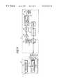
- FIG. 20schematically illustrates in more detail, the main components of the local monitoring node 263 and some of the sensor terminals 267 .
- each sensor terminal 267comprises a controller 271 which is operable to receive signals from one or more sensors 273 and to output modulation data in dependence thereon for modulating the light output by a light source 279 .
- the local monitoring node 263comprises a video camera 283 for monitoring the light output from the respective sensor terminals 267 , and to output appropriate video signals 285 to a signal detector 287 .
- the sensors 273sense the local temperature/movement etc and supply corresponding sensor signals to the controller unit 271 of the respective sensor terminal 267 .
- the controller unit 271analyses the sensor data and, if appropriate, generates modulation data 275 for modulating the light 277 produced by the corresponding light source 279 .
- the output video signal 285 from the video camera 283changes, due to the modulation of the light source 279 and this change is detected by the signal detector 287 .
- the signal detector 287can identify from which sensor terminal 267 the modulated light came from simply by determining the location of the modulated light within one frame of the video signal 285 , because the sensor terminals 267 are fixed relative to the local monitoring node 263 .
- the modulation performed to the light 277will simply be to switch on the light source 279 in response to a particular event sensed by the corresponding sensor or sensors 273 .
- the light 277might be modulated to include data describing the event which has been sensed by the sensor 273 .
- a telecentric lenscould be used with an array of photo detectors placed at the focal plane of the telecentric lens, with each detector element of the array being associated with a predetermined sensor terminal 267 .
- the array of detectorscomprises an array of charged coupled devices, with a respective charge coupled device being assigned to a corresponding sensor terminal 267 .
- the monitoring system described abovehas many applications. For example, it can be used in security applications for monitoring a number of different warehouses and for relaying the sensed data back to a central security station.
- the systemcould be employed in industrial applications where the sensed conditions are used to control the industrial plant.
- each of the sensor terminals 267might have a corresponding actuation terminal which is controlled by sending appropriate control data from the central monitoring system back through the optical fibre bundles 5 to the local monitoring nodes 263 and back to the corresponding actuation terminals associated with the sensor terminal.
Landscapes
- Engineering & Computer Science (AREA)
- Physics & Mathematics (AREA)
- Electromagnetism (AREA)
- Computer Networks & Wireless Communication (AREA)
- Signal Processing (AREA)
- Computing Systems (AREA)
- Optical Communication System (AREA)
- Cable Transmission Systems, Equalization Of Radio And Reduction Of Echo (AREA)
- Closed-Circuit Television Systems (AREA)
- Time-Division Multiplex Systems (AREA)
- Data Exchanges In Wide-Area Networks (AREA)
- Mobile Radio Communication Systems (AREA)
- Saccharide Compounds (AREA)
Abstract
Description
Claims (109)
Priority Applications (1)
| Application Number | Priority Date | Filing Date | Title |
|---|---|---|---|
| US09/950,004US20020141011A1 (en) | 1997-02-11 | 2001-09-12 | Optical free space signalling system |
Applications Claiming Priority (5)
| Application Number | Priority Date | Filing Date | Title |
|---|---|---|---|
| GBGB9702726.2AGB9702726D0 (en) | 1997-02-11 | 1997-02-11 | Optical point-to-multipoint transmission |
| GB9702726 | 1997-02-11 | ||
| GB9706062 | 1997-03-24 | ||
| GBGB9706062.8AGB9706062D0 (en) | 1997-03-24 | 1997-03-24 | Optical retro-reflector |
| PCT/GB1998/000421WO1998035328A2 (en) | 1997-02-11 | 1998-02-11 | Signalling system |
Related Child Applications (1)
| Application Number | Title | Priority Date | Filing Date |
|---|---|---|---|
| US09/950,004Continuation-In-PartUS20020141011A1 (en) | 1997-02-11 | 2001-09-12 | Optical free space signalling system |
Publications (1)
| Publication Number | Publication Date |
|---|---|
| US6624916B1true US6624916B1 (en) | 2003-09-23 |
Family
ID=26310962
Family Applications (1)
| Application Number | Title | Priority Date | Filing Date |
|---|---|---|---|
| US09/367,223Expired - Fee RelatedUS6624916B1 (en) | 1997-02-11 | 1998-02-11 | Signalling system |
Country Status (8)
| Country | Link |
|---|---|
| US (1) | US6624916B1 (en) |
| EP (2) | EP0960492B1 (en) |
| JP (1) | JP2002511204A (en) |
| AT (1) | ATE265110T1 (en) |
| AU (1) | AU6000898A (en) |
| CA (1) | CA2279934A1 (en) |
| DE (1) | DE69823336T2 (en) |
| WO (1) | WO1998035328A2 (en) |
Cited By (89)
| Publication number | Priority date | Publication date | Assignee | Title |
|---|---|---|---|---|
| US20010013967A1 (en)* | 2000-02-10 | 2001-08-16 | Tsumura Research Institute Co. | Multi-channel optical communication system that controls optical reflection for each channel and optical transmitting and receiving apparatuses therefor |
| US20020033981A1 (en)* | 2000-09-20 | 2002-03-21 | Keller Robert C. | Optical wireless multiport hub |
| US6829439B1 (en)* | 2000-06-08 | 2004-12-07 | Meklyn Enterprises Limited | Optical communication device |
| WO2005041450A1 (en)* | 2003-10-17 | 2005-05-06 | Bae Systems Plc | Retroreflective devices and systems |
| US20050135812A1 (en)* | 2003-12-18 | 2005-06-23 | Pease David M. | Laser-based communications with a remote information source |
| US20070075265A1 (en)* | 2005-09-30 | 2007-04-05 | Virgin Islands Microsystems, Inc. | Coupled nano-resonating energy emitting structures |
| US20070177880A1 (en)* | 2004-03-15 | 2007-08-02 | Nir Karasikov | Retromodulation-based data communication |
| US20070189779A1 (en)* | 2005-08-01 | 2007-08-16 | Murphy James L | System and method for transmitting analog signals with a modulating retroreflector and hybrid amplitude and frequency modulation |
| US20070200784A1 (en)* | 2006-02-28 | 2007-08-30 | Virgin Islands Microsystems, Inc. | Integrated filter in antenna-based detector |
| US20070200071A1 (en)* | 2006-02-28 | 2007-08-30 | Virgin Islands Microsystems, Inc. | Coupling output from a micro resonator to a plasmon transmission line |
| US20070258492A1 (en)* | 2006-05-05 | 2007-11-08 | Virgin Islands Microsystems, Inc. | Light-emitting resonant structure driving raman laser |
| US20070258689A1 (en)* | 2006-05-05 | 2007-11-08 | Virgin Islands Microsystems, Inc. | Coupling electromagnetic wave through microcircuit |
| US20070258146A1 (en)* | 2006-05-05 | 2007-11-08 | Virgin Islands Microsystems, Inc. | Reflecting filtering cover |
| US20070257208A1 (en)* | 2006-05-05 | 2007-11-08 | Virgin Islands Microsystems, Inc. | Electron accelerator for ultra-small resonant structures |
| WO2007133226A1 (en)* | 2006-04-26 | 2007-11-22 | Virgin Islands Microsystems, Inc. | Selectable frequency emr emitter |
| US20070297805A1 (en)* | 2006-06-23 | 2007-12-27 | William Rabinovich | Optical communication system with cats-eye modulating retro-reflector (mrr) assembly, the cats-eye mrr assembly thereof, and the method of optical communication |
| US7317876B1 (en)* | 2004-02-26 | 2008-01-08 | Bbn Technologies Corp. | Medium access control for retro-reflectors |
| US7342441B2 (en) | 2006-05-05 | 2008-03-11 | Virgin Islands Microsystems, Inc. | Heterodyne receiver array using resonant structures |
| US20080069509A1 (en)* | 2006-09-19 | 2008-03-20 | Virgin Islands Microsystems, Inc. | Microcircuit using electromagnetic wave routing |
| US20080247764A1 (en)* | 2005-10-19 | 2008-10-09 | Qinetiq Limited | Method and System For Synchronising an Optical Transmitter With an Optical Modulator |
| US7436177B2 (en) | 2006-05-05 | 2008-10-14 | Virgin Islands Microsystems, Inc. | SEM test apparatus |
| US7442940B2 (en) | 2006-05-05 | 2008-10-28 | Virgin Island Microsystems, Inc. | Focal plane array incorporating ultra-small resonant structures |
| US7470920B2 (en) | 2006-01-05 | 2008-12-30 | Virgin Islands Microsystems, Inc. | Resonant structure-based display |
| US7476907B2 (en) | 2006-05-05 | 2009-01-13 | Virgin Island Microsystems, Inc. | Plated multi-faceted reflector |
| US7492868B2 (en) | 2006-04-26 | 2009-02-17 | Virgin Islands Microsystems, Inc. | Source of x-rays |
| US20090103925A1 (en)* | 2005-09-27 | 2009-04-23 | Ortal Alpert | Directional Light Transmitter and Receiver |
| US7554083B2 (en) | 2006-05-05 | 2009-06-30 | Virgin Islands Microsystems, Inc. | Integration of electromagnetic detector on integrated chip |
| US7557647B2 (en) | 2006-05-05 | 2009-07-07 | Virgin Islands Microsystems, Inc. | Heterodyne receiver using resonant structures |
| US7557365B2 (en) | 2005-09-30 | 2009-07-07 | Virgin Islands Microsystems, Inc. | Structures and methods for coupling energy from an electromagnetic wave |
| US7558490B2 (en) | 2006-04-10 | 2009-07-07 | Virgin Islands Microsystems, Inc. | Resonant detector for optical signals |
| US7560716B2 (en) | 2006-09-22 | 2009-07-14 | Virgin Islands Microsystems, Inc. | Free electron oscillator |
| US7569836B2 (en) | 2006-05-05 | 2009-08-04 | Virgin Islands Microsystems, Inc. | Transmission of data between microchips using a particle beam |
| US7573045B2 (en) | 2006-05-15 | 2009-08-11 | Virgin Islands Microsystems, Inc. | Plasmon wave propagation devices and methods |
| US20090202254A1 (en)* | 2008-02-12 | 2009-08-13 | Arun Kumar Majumdar | Wide field-of-view amplified fiber-retro for secure high data rate communications and remote data transfer |
| US7579609B2 (en) | 2005-12-14 | 2009-08-25 | Virgin Islands Microsystems, Inc. | Coupling light of light emitting resonator to waveguide |
| US7583370B2 (en) | 2006-05-05 | 2009-09-01 | Virgin Islands Microsystems, Inc. | Resonant structures and methods for encoding signals into surface plasmons |
| US7586097B2 (en) | 2006-01-05 | 2009-09-08 | Virgin Islands Microsystems, Inc. | Switching micro-resonant structures using at least one director |
| US7586167B2 (en) | 2006-05-05 | 2009-09-08 | Virgin Islands Microsystems, Inc. | Detecting plasmons using a metallurgical junction |
| US7619373B2 (en) | 2006-01-05 | 2009-11-17 | Virgin Islands Microsystems, Inc. | Selectable frequency light emitter |
| US20090285583A1 (en)* | 2008-05-15 | 2009-11-19 | Winker Bruce K | Snr enhancement in modulating retroreflector optical communication links |
| US7655934B2 (en) | 2006-06-28 | 2010-02-02 | Virgin Island Microsystems, Inc. | Data on light bulb |
| US7659513B2 (en) | 2006-12-20 | 2010-02-09 | Virgin Islands Microsystems, Inc. | Low terahertz source and detector |
| US7679067B2 (en) | 2006-05-26 | 2010-03-16 | Virgin Island Microsystems, Inc. | Receiver array using shared electron beam |
| US7710040B2 (en) | 2006-05-05 | 2010-05-04 | Virgin Islands Microsystems, Inc. | Single layer construction for ultra small devices |
| US7718977B2 (en) | 2006-05-05 | 2010-05-18 | Virgin Island Microsystems, Inc. | Stray charged particle removal device |
| US7723698B2 (en) | 2006-05-05 | 2010-05-25 | Virgin Islands Microsystems, Inc. | Top metal layer shield for ultra-small resonant structures |
| US7728702B2 (en) | 2006-05-05 | 2010-06-01 | Virgin Islands Microsystems, Inc. | Shielding of integrated circuit package with high-permeability magnetic material |
| US7728397B2 (en) | 2006-05-05 | 2010-06-01 | Virgin Islands Microsystems, Inc. | Coupled nano-resonating energy emitting structures |
| US20100135668A1 (en)* | 2008-11-20 | 2010-06-03 | Cubic Corporation | Compact wide-angle pixellated active optical link |
| US20100135670A1 (en)* | 2008-11-21 | 2010-06-03 | Cubic Corporation | Phase-modulating communication device |
| US7732786B2 (en) | 2006-05-05 | 2010-06-08 | Virgin Islands Microsystems, Inc. | Coupling energy in a plasmon wave to an electron beam |
| US7741934B2 (en) | 2006-05-05 | 2010-06-22 | Virgin Islands Microsystems, Inc. | Coupling a signal through a window |
| US7746532B2 (en) | 2006-05-05 | 2010-06-29 | Virgin Island Microsystems, Inc. | Electro-optical switching system and method |
| US7791291B2 (en) | 2005-09-30 | 2010-09-07 | Virgin Islands Microsystems, Inc. | Diamond field emission tip and a method of formation |
| US7791053B2 (en) | 2007-10-10 | 2010-09-07 | Virgin Islands Microsystems, Inc. | Depressed anode with plasmon-enabled devices such as ultra-small resonant structures |
| US20100320362A1 (en)* | 2008-01-03 | 2010-12-23 | Ortal Alpert | Wireless laser power transmitter |
| US7876793B2 (en) | 2006-04-26 | 2011-01-25 | Virgin Islands Microsystems, Inc. | Micro free electron laser (FEL) |
| US7986113B2 (en) | 2006-05-05 | 2011-07-26 | Virgin Islands Microsystems, Inc. | Selectable frequency light emitter |
| US7990336B2 (en) | 2007-06-19 | 2011-08-02 | Virgin Islands Microsystems, Inc. | Microwave coupled excitation of solid state resonant arrays |
| US8188431B2 (en) | 2006-05-05 | 2012-05-29 | Jonathan Gorrell | Integration of vacuum microelectronic device with integrated circuit |
| US8224189B1 (en) | 2007-02-02 | 2012-07-17 | Sunlight Photonics Inc. | Retro-directive target for free-space optical communication and method of producing the same |
| WO2012172541A1 (en)* | 2011-06-13 | 2012-12-20 | Wi-Charge Ltd. | Spatially distributed laser resonator |
| US8379286B2 (en) | 2010-05-28 | 2013-02-19 | The United States Of America, As Represented By The Secretary Of The Navy | Integrated angle of arrival sensing and duplex communication with cats-eye multiple quantum well modulating retroreflector |
| US8422034B2 (en) | 2010-04-21 | 2013-04-16 | Faro Technologies, Inc. | Method and apparatus for using gestures to control a laser tracker |
| US8467071B2 (en) | 2010-04-21 | 2013-06-18 | Faro Technologies, Inc. | Automatic measurement of dimensional data with a laser tracker |
| US8467072B2 (en) | 2011-02-14 | 2013-06-18 | Faro Technologies, Inc. | Target apparatus and method of making a measurement with the target apparatus |
| US8537371B2 (en) | 2010-04-21 | 2013-09-17 | Faro Technologies, Inc. | Method and apparatus for using gestures to control a laser tracker |
| US8655189B2 (en) | 2010-06-18 | 2014-02-18 | Exelis, Inc. | Optical modulation utilizing structures including metamaterials |
| US8724119B2 (en) | 2010-04-21 | 2014-05-13 | Faro Technologies, Inc. | Method for using a handheld appliance to select, lock onto, and track a retroreflector with a laser tracker |
| US9041914B2 (en) | 2013-03-15 | 2015-05-26 | Faro Technologies, Inc. | Three-dimensional coordinate scanner and method of operation |
| US9164173B2 (en) | 2011-04-15 | 2015-10-20 | Faro Technologies, Inc. | Laser tracker that uses a fiber-optic coupler and an achromatic launch to align and collimate two wavelengths of light |
| US9207309B2 (en) | 2011-04-15 | 2015-12-08 | Faro Technologies, Inc. | Six degree-of-freedom laser tracker that cooperates with a remote line scanner |
| US20160134367A1 (en)* | 2013-07-01 | 2016-05-12 | Nokia Technologies Oy | Directional optical communications |
| US9377885B2 (en) | 2010-04-21 | 2016-06-28 | Faro Technologies, Inc. | Method and apparatus for locking onto a retroreflector with a laser tracker |
| US9395174B2 (en) | 2014-06-27 | 2016-07-19 | Faro Technologies, Inc. | Determining retroreflector orientation by optimizing spatial fit |
| US9400170B2 (en) | 2010-04-21 | 2016-07-26 | Faro Technologies, Inc. | Automatic measurement of dimensional data within an acceptance region by a laser tracker |
| US9482529B2 (en) | 2011-04-15 | 2016-11-01 | Faro Technologies, Inc. | Three-dimensional coordinate scanner and method of operation |
| US9482755B2 (en) | 2008-11-17 | 2016-11-01 | Faro Technologies, Inc. | Measurement system having air temperature compensation between a target and a laser tracker |
| US9638507B2 (en) | 2012-01-27 | 2017-05-02 | Faro Technologies, Inc. | Measurement machine utilizing a barcode to identify an inspection plan for an object |
| US9686532B2 (en) | 2011-04-15 | 2017-06-20 | Faro Technologies, Inc. | System and method of acquiring three-dimensional coordinates using multiple coordinate measurement devices |
| US9772394B2 (en) | 2010-04-21 | 2017-09-26 | Faro Technologies, Inc. | Method and apparatus for following an operator and locking onto a retroreflector with a laser tracker |
| US9917645B2 (en)* | 2016-05-25 | 2018-03-13 | Google Llc | Phase sensitive beam tracking |
| WO2019014064A1 (en)* | 2017-07-11 | 2019-01-17 | Cubic Corporation | Large aperture, high-speed optical tags |
| US10411797B1 (en)* | 2018-06-08 | 2019-09-10 | SA Photonics, Inc. | Free space optical node with fiber bundle |
| US10771155B2 (en)* | 2017-09-28 | 2020-09-08 | Soraa Laser Diode, Inc. | Intelligent visible light with a gallium and nitrogen containing laser source |
| WO2022218918A1 (en)* | 2021-04-13 | 2022-10-20 | Signify Holding B.V. | An optical detector |
| US20230050177A1 (en)* | 2017-09-28 | 2023-02-16 | Kyocera Sld Laser, Inc. | Laser based white light system configured for communication |
| US20240405867A1 (en)* | 2023-06-01 | 2024-12-05 | Qualcomm Incorporated | Utilizing curved focal planes for optical wireless communication |
| US12368515B2 (en)* | 2017-12-19 | 2025-07-22 | Panasonic Intellectual Property Corporation Of America | Transmission method, reception method, transmission device, and reception device |
Families Citing this family (20)
| Publication number | Priority date | Publication date | Assignee | Title |
|---|---|---|---|---|
| WO2001005072A1 (en)* | 1999-07-08 | 2001-01-18 | Quantumbeam Limited | Signalling system |
| AU5995400A (en)* | 1999-07-08 | 2001-01-30 | Quantumbeam Limited | Signalling system |
| AU6166800A (en)* | 1999-07-08 | 2001-01-30 | Quantumbeam Limited | Signalling system |
| WO2001045981A2 (en) | 1999-12-22 | 2001-06-28 | Quantumbeam Limited | Optical free space signalling system |
| EP1254526A2 (en)* | 2000-02-07 | 2002-11-06 | QuantumBeam Limited | Optical free space signalling system |
| WO2001078262A2 (en)* | 2000-04-07 | 2001-10-18 | The Regents Of The University Of California | Remotely-interrogated high data rate free space laser communications link |
| EP1162770A3 (en)* | 2000-06-08 | 2005-03-09 | Sunflower Technologies, Ltd. | Free space optical communication device |
| GB0017048D0 (en)* | 2000-07-11 | 2000-08-30 | Scient Generics Ltd | Alternative optical system |
| US20020071160A1 (en)* | 2000-10-16 | 2002-06-13 | Andrew Pavelchek | Establishment and maintenance of optical links between optical transceiver nodes in free-space optical communications networks |
| US6522437B2 (en)* | 2001-02-15 | 2003-02-18 | Harris Corporation | Agile multi-beam free-space optical communication apparatus |
| DE10208796A1 (en)* | 2002-03-01 | 2003-09-04 | Endress & Hauser Gmbh & Co Kg | Optoelectronic communication system |
| GB0205010D0 (en)* | 2002-03-04 | 2002-04-17 | Quantumbeam Ltd | Alignment system |
| WO2003075493A2 (en)* | 2002-03-05 | 2003-09-12 | Scientific Generics Ltd. | Optical free-space signalling system |
| US7729030B2 (en) | 2002-10-21 | 2010-06-01 | Hrl Laboratories, Llc | Optical retro-reflective apparatus with modulation capability |
| GB2418028B (en) | 2003-05-07 | 2007-08-01 | Qinetiq Ltd | Dynamic optical reflector and interrogation system |
| JP2009239800A (en)* | 2008-03-28 | 2009-10-15 | Nec Corp | Communication device and communicating system |
| US8704676B2 (en) | 2011-08-09 | 2014-04-22 | Qualcomm Incorporated | Dynamic road markers to provide visual feedback as to vehicle speed |
| US9076339B2 (en) | 2013-02-15 | 2015-07-07 | Qualcomm Incorporated | Facilitating vehicle merging utilizing road markers |
| EP4318013A4 (en)* | 2021-03-31 | 2024-06-19 | Sumitomo Electric Industries, Ltd. | MAGNETOOPTIC DIAMOND SENSOR AND MAGNETOOPTIC DIAMOND SENSOR SYSTEM |
| DE102023119852B4 (en)* | 2023-07-26 | 2025-05-22 | Technische Universität Dresden, Körperschaft des öffentlichen Rechts | Retroreflector communication system, especially for satellite communication |
Citations (90)
| Publication number | Priority date | Publication date | Assignee | Title |
|---|---|---|---|---|
| GB1032529A (en) | 1963-04-18 | 1966-06-08 | Nasa | Improvements in or relating to communication systems for acoustical vibrations |
| US3989942A (en) | 1974-12-13 | 1976-11-02 | International Telephone And Telegraph Corporation | Retro-reflecting laser responser and data modulator |
| US4064434A (en) | 1976-06-07 | 1977-12-20 | Rca Limited | Retro-reflection communication system |
| US4096380A (en)* | 1975-07-28 | 1978-06-20 | Kurt Eichweber | System for transmitting light signals between a missile and a missile control station |
| US4099050A (en) | 1970-07-10 | 1978-07-04 | The United States Of America As Represented By The Secretary Of The Air Force | Codable optical transponder |
| US4131791A (en) | 1975-12-08 | 1978-12-26 | General Electric Company | Search and locate system |
| US4143263A (en) | 1974-11-08 | 1979-03-06 | Kurt Eichweber | Receiver-transmitter device for transmitting data by means of focused modulated, light beams |
| US4325146A (en) | 1979-12-20 | 1982-04-13 | Lennington John W | Non-synchronous object identification system |
| US4361911A (en) | 1981-05-21 | 1982-11-30 | The United States Of American As Represented By The Secretary Of The Army | Laser retroreflector system for identification of friend or foe |
| GB2099992A (en) | 1981-03-25 | 1982-12-15 | Goldstein Pinchas | Optical sensing communication or viewing apparatus incorporating adapted reflector assemblies |
| US4364631A (en) | 1979-10-05 | 1982-12-21 | Thomson - Csf | Catadioptric device intended for an optical responder |
| GB2125647A (en) | 1982-08-10 | 1984-03-07 | Standard Telephones Cables Ltd | Active optical transponder system |
| US4456793A (en) | 1982-06-09 | 1984-06-26 | Bell Telephone Laboratories, Incorporated | Cordless telephone system |
| US4570062A (en) | 1982-05-01 | 1986-02-11 | Hitachi Kidenkogyo Kabushiki Kaisha | System for optically transferring information between a moving object and a fixed position |
| WO1986003637A1 (en) | 1984-12-13 | 1986-06-19 | Veeco Integrated Automation Inc. | Vehicle to fixed station infrared communications link |
| GB2186457A (en) | 1984-10-18 | 1987-08-12 | Gec Avionics | Optical communications |
| US4717913A (en) | 1985-08-29 | 1988-01-05 | Johnson Service Company | Data telemetry system using diffused infrared light |
| US4727600A (en) | 1985-02-15 | 1988-02-23 | Emik Avakian | Infrared data communication system |
| US4740708A (en)* | 1987-01-06 | 1988-04-26 | International Business Machines Corporation | Semiconductor wafer surface inspection apparatus and method |
| GB2196809A (en) | 1986-10-23 | 1988-05-05 | Plessey Co Plc | Optical communication system |
| US4809257A (en) | 1985-04-02 | 1989-02-28 | International Business Machines Corporation | Hierarchical distributed infrared communication system |
| US4864651A (en) | 1985-10-22 | 1989-09-05 | Canon Kabushiki Kaisha | Light communication apparatus with tracking ability |
| GB2215089A (en) | 1988-02-15 | 1989-09-13 | Marconi Co Ltd | Laser beam steering |
| US4882770A (en) | 1987-12-14 | 1989-11-21 | H. M. Electronics, Inc. | Wireless optical communication system |
| US4888816A (en) | 1989-01-05 | 1989-12-19 | The United States Of America As Represented By The Secretary Of The Navy | Two-way optic communication system for atmospheric use |
| GB2221810A (en) | 1988-07-08 | 1990-02-14 | Univ London | Optical transmission arrangement |
| GB2222335A (en) | 1988-08-24 | 1990-02-28 | Stc Plc | Optical communication system |
| US4933928A (en) | 1987-04-28 | 1990-06-12 | British Aerospace Public Limited Company | Optical communications apparatus for sending optical transmissions to a plurality of remote stations |
| GB2226729A (en) | 1988-11-01 | 1990-07-04 | Bicc Plc | Infrared communication network |
| US4941205A (en) | 1984-06-06 | 1990-07-10 | Ncr Corporation | Bidirectional optical data communications system |
| US4959874A (en) | 1987-12-28 | 1990-09-25 | Ncr Corporation | Optical wireless communication system |
| US4982445A (en) | 1987-11-20 | 1991-01-01 | British Aerospace Public Limited Company | Laser beam communication between spacecraft |
| US4983021A (en) | 1988-08-10 | 1991-01-08 | Fergason James L | Modulated retroreflector system |
| WO1991009477A1 (en) | 1989-12-14 | 1991-06-27 | Bicc Network Solutions, Inc. | Free space local area network system |
| GB2240681A (en) | 1990-01-23 | 1991-08-07 | British Telecomm | Communicator |
| US5062150A (en) | 1989-01-23 | 1991-10-29 | Massachusetts Institute Of Technology | Fiber-based free-space optical system |
| GB2245116A (en) | 1990-06-13 | 1991-12-18 | Gen Electric Co Plc | Telecommunications reflective optical links |
| US5091636A (en) | 1988-02-23 | 1992-02-25 | Sony Corporation | Apparatus for detecting modulated informations from emitted light turned by an object |
| US5099346A (en) | 1988-01-27 | 1992-03-24 | Spectrix Corporation | Infrared communications network |
| US5117301A (en) | 1989-07-03 | 1992-05-26 | Toshihiro Tsumura | System for transmitting information to moving object |
| US5121242A (en) | 1991-02-04 | 1992-06-09 | Martin Marietta Corporation | Retro-reflective optical transceiver |
| US5121243A (en) | 1989-09-21 | 1992-06-09 | Hm Electronics | Wireless optical communication system utilizing a single optical carrier frequency |
| US5126879A (en) | 1989-09-16 | 1992-06-30 | Hommelwerke Gmbh | Optical retro-reflector |
| US5142399A (en) | 1989-12-01 | 1992-08-25 | Societe Anonyme De Telecommunications | Message transmission system |
| EP0503874A2 (en) | 1991-03-15 | 1992-09-16 | THERMA-WAVE, INC. (a Delaware corporation) | Optical measurement device with enhanced sensitivity |
| US5218356A (en) | 1991-05-31 | 1993-06-08 | Guenther Knapp | Wireless indoor data relay system |
| US5230005A (en)* | 1991-11-05 | 1993-07-20 | The United States Of America As Represented By The Secretary Of The Navy | Electronic tuning of a broadband laser |
| US5229593A (en) | 1991-10-08 | 1993-07-20 | International Business Machines Corporation | Apparatus and method for safe, free space laser communication |
| US5247381A (en) | 1991-01-16 | 1993-09-21 | Infralan Technologies, Inc. | Apparatus and method for automatically reconfiguring, free space local area network systems |
| US5289306A (en) | 1991-03-27 | 1994-02-22 | Victor Company Of Japan | Repeater system |
| US5315645A (en) | 1990-12-10 | 1994-05-24 | Tek Electronics Manufacturing Corporation | Communication apparatus utilizing digital optical signals |
| US5317442A (en) | 1993-07-29 | 1994-05-31 | The United States Of America As Represented By The Secretary Of The Army | Mutually pumped phase conjugator for remote identification |
| US5329395A (en) | 1991-12-28 | 1994-07-12 | Sony Corporation | Optical atmospheric communication system |
| US5349463A (en) | 1990-08-17 | 1994-09-20 | Victor Company Of Japan | Optical radio repeater with signal quality detection |
| US5359446A (en) | 1992-09-10 | 1994-10-25 | Eldec Corporation | Wide-angle, high-speed, free-space optical communications system |
| US5408350A (en) | 1991-10-04 | 1995-04-18 | Alcatel Cit | Bidirectional transmission system, especially one using optical fiber, employing a single carrier for both transmission directions |
| WO1995015624A1 (en) | 1993-12-02 | 1995-06-08 | Radiance Communications, Inc | Infrared local area network |
| US5475520A (en) | 1994-06-22 | 1995-12-12 | Hughes Aircraft Company | Satellite communications system |
| US5493436A (en) | 1991-07-25 | 1996-02-20 | Kokusai Denshin Denwa Company, Limited | Optical wave transmission |
| US5517016A (en) | 1994-03-31 | 1996-05-14 | The United States Of America As Represented By The Administrator Of The National Aeronautics And Space Administration | Lasercom system architecture with reduced complexity |
| US5559624A (en) | 1993-03-11 | 1996-09-24 | Lucent Technologies Inc. | Communication system based on remote interrogation of terminal equipment |
| EP0749219A2 (en) | 1995-06-14 | 1996-12-18 | Nec Corporation | Infrared spatial communication system capable of reducing a processing amount of data communication devices during communication |
| US5627669A (en) | 1991-11-13 | 1997-05-06 | Canon Kabushiki Kaisha | Optical transmitter-receiver |
| US5659413A (en) | 1995-02-28 | 1997-08-19 | The Mitre Corporation | Laser satellite communication system |
| EP0813073A2 (en) | 1996-06-14 | 1997-12-17 | Xerox Corporation | Object identification and precision localization through combined video and infrared signals |
| EP0813040A2 (en) | 1996-06-14 | 1997-12-17 | Xerox Corporation | Precision spatial mapping with combined video and infrared signals |
| US5710671A (en) | 1995-09-05 | 1998-01-20 | Temic Telefunken Microelectronic Gmbh | Optical system |
| US5736730A (en) | 1995-02-09 | 1998-04-07 | Dassault Electronique | Device for receiving electromagnetic signals with an energy correction means |
| US5777768A (en) | 1995-09-01 | 1998-07-07 | Astroterra Corporation | Multiple transmitter laser link |
| US5786923A (en) | 1996-03-29 | 1998-07-28 | Dominion Communications, Llc | Point-to-multipoint wide area telecommunications network via atmospheric laser transmission through a remote optical router |
| DE19702634A1 (en) | 1997-01-25 | 1998-07-30 | Leuze Electronic Gmbh & Co | Arrangement of two opposing data light barriers |
| EP0859478A2 (en) | 1997-02-13 | 1998-08-19 | AT&T Corp. | Wireless communications systems employing free-space optical communications links |
| US5818619A (en) | 1995-06-15 | 1998-10-06 | Jolt Ltd. | Wireless communication system |
| US5819164A (en) | 1996-01-29 | 1998-10-06 | The United States Of America As Represented By The Secretary Of The Army | Modulated retroreflection system for secure communication and identification |
| US5822099A (en) | 1995-08-31 | 1998-10-13 | Sony Corporation | Light communication system |
| WO1998057451A1 (en) | 1997-06-13 | 1998-12-17 | Vector Technology Limited | Laser link systems |
| US5880867A (en) | 1996-03-29 | 1999-03-09 | Intermec Ip Corp. | Infrared backbone communication network having a radio frequency backup channel |
| US5953146A (en) | 1997-01-30 | 1999-09-14 | At&T Corp. | Method and apparatus for tracking alignment in wireless optical communications |
| US5969842A (en) | 1996-03-22 | 1999-10-19 | Wireless Communications Products Llc | Method and apparatus for cordless infrared communication |
| US5973310A (en) | 1997-12-10 | 1999-10-26 | Ems Technologies Canada, Ltd. | Optical acquisition and tracking system |
| US6014478A (en) | 1995-06-19 | 2000-01-11 | Siemens Aktiengesellschaft | Optical switch |
| US6076939A (en) | 1996-12-06 | 2000-06-20 | Contraves Space Ag | Alignment device for aligning an optical transmitting beam with an optical receiving beam |
| US6104512A (en) | 1998-01-23 | 2000-08-15 | Motorola, Inc. | Method for adjusting the power level of an infrared signal |
| US6154299A (en) | 1998-06-15 | 2000-11-28 | The United States Of America As Represented By The Secretary Of The Navy | Modulating retroreflector using multiple quantum well technology |
| US6256129B1 (en) | 1997-03-28 | 2001-07-03 | Samsung Electronics Co., Ltd. | Portable computer and method of automatically controlling direction of infrared signal transmission and reception |
| US6285481B1 (en) | 1997-09-05 | 2001-09-04 | Trex Communications Corporation | Free-space laser communications error control system |
| US6301307B1 (en) | 1996-12-23 | 2001-10-09 | Canon Kabushiki Kaisha | Methods and apparatuses for the transmission and receipt of digital data modulated using quadrature amplitude modulation, and communication devices utilizing such apparatuses and methods |
| US6310707B1 (en) | 1996-10-25 | 2001-10-30 | Seiko Epson Corporation | Optical wireless data communication system, and transmitter and receiver used therefor |
| US6314163B1 (en) | 1997-01-17 | 2001-11-06 | The Regents Of The University Of California | Hybrid universal broadband telecommunications using small radio cells interconnected by free-space optical links |
| US6353491B1 (en) | 1997-08-26 | 2002-03-05 | Rohm Co., Ltd. | Optical communication module |
Family Cites Families (1)
| Publication number | Priority date | Publication date | Assignee | Title |
|---|---|---|---|---|
| GB9005647D0 (en)* | 1990-03-13 | 1990-05-09 | Secr Defence | Optical multiplexer |
- 1998
- 1998-02-11AUAU60008/98Apatent/AU6000898A/ennot_activeAbandoned
- 1998-02-11WOPCT/GB1998/000421patent/WO1998035328A2/enactiveIP Right Grant
- 1998-02-11USUS09/367,223patent/US6624916B1/ennot_activeExpired - Fee Related
- 1998-02-11EPEP98903190Apatent/EP0960492B1/ennot_activeExpired - Lifetime
- 1998-02-11CACA002279934Apatent/CA2279934A1/ennot_activeAbandoned
- 1998-02-11EPEP02079491Apatent/EP1294112A3/ennot_activeWithdrawn
- 1998-02-11DEDE69823336Tpatent/DE69823336T2/ennot_activeExpired - Fee Related
- 1998-02-11ATAT98903190Tpatent/ATE265110T1/ennot_activeIP Right Cessation
- 1998-02-11JPJP53401898Apatent/JP2002511204A/enactivePending
Patent Citations (92)
| Publication number | Priority date | Publication date | Assignee | Title |
|---|---|---|---|---|
| GB1032529A (en) | 1963-04-18 | 1966-06-08 | Nasa | Improvements in or relating to communication systems for acoustical vibrations |
| US4099050A (en) | 1970-07-10 | 1978-07-04 | The United States Of America As Represented By The Secretary Of The Air Force | Codable optical transponder |
| US4143263A (en) | 1974-11-08 | 1979-03-06 | Kurt Eichweber | Receiver-transmitter device for transmitting data by means of focused modulated, light beams |
| US3989942A (en) | 1974-12-13 | 1976-11-02 | International Telephone And Telegraph Corporation | Retro-reflecting laser responser and data modulator |
| US4096380A (en)* | 1975-07-28 | 1978-06-20 | Kurt Eichweber | System for transmitting light signals between a missile and a missile control station |
| GB1529388A (en) | 1975-07-28 | 1978-10-18 | Precitronic | Apparatus for transmitting signals between a missile and a missile control station |
| US4131791A (en) | 1975-12-08 | 1978-12-26 | General Electric Company | Search and locate system |
| US4064434A (en) | 1976-06-07 | 1977-12-20 | Rca Limited | Retro-reflection communication system |
| US4364631A (en) | 1979-10-05 | 1982-12-21 | Thomson - Csf | Catadioptric device intended for an optical responder |
| US4325146A (en) | 1979-12-20 | 1982-04-13 | Lennington John W | Non-synchronous object identification system |
| US4727593A (en)* | 1981-03-25 | 1988-02-23 | Pinchas Goldstein | Passive line-of-sight optical switching apparatus |
| GB2099992A (en) | 1981-03-25 | 1982-12-15 | Goldstein Pinchas | Optical sensing communication or viewing apparatus incorporating adapted reflector assemblies |
| US4361911A (en) | 1981-05-21 | 1982-11-30 | The United States Of American As Represented By The Secretary Of The Army | Laser retroreflector system for identification of friend or foe |
| US4570062A (en) | 1982-05-01 | 1986-02-11 | Hitachi Kidenkogyo Kabushiki Kaisha | System for optically transferring information between a moving object and a fixed position |
| US4456793A (en) | 1982-06-09 | 1984-06-26 | Bell Telephone Laboratories, Incorporated | Cordless telephone system |
| GB2125647A (en) | 1982-08-10 | 1984-03-07 | Standard Telephones Cables Ltd | Active optical transponder system |
| US4941205A (en) | 1984-06-06 | 1990-07-10 | Ncr Corporation | Bidirectional optical data communications system |
| GB2186457A (en) | 1984-10-18 | 1987-08-12 | Gec Avionics | Optical communications |
| WO1986003637A1 (en) | 1984-12-13 | 1986-06-19 | Veeco Integrated Automation Inc. | Vehicle to fixed station infrared communications link |
| US4727600A (en) | 1985-02-15 | 1988-02-23 | Emik Avakian | Infrared data communication system |
| US4809257A (en) | 1985-04-02 | 1989-02-28 | International Business Machines Corporation | Hierarchical distributed infrared communication system |
| US4717913A (en) | 1985-08-29 | 1988-01-05 | Johnson Service Company | Data telemetry system using diffused infrared light |
| US4864651A (en) | 1985-10-22 | 1989-09-05 | Canon Kabushiki Kaisha | Light communication apparatus with tracking ability |
| GB2196809A (en) | 1986-10-23 | 1988-05-05 | Plessey Co Plc | Optical communication system |
| US4740708A (en)* | 1987-01-06 | 1988-04-26 | International Business Machines Corporation | Semiconductor wafer surface inspection apparatus and method |
| US4933928A (en) | 1987-04-28 | 1990-06-12 | British Aerospace Public Limited Company | Optical communications apparatus for sending optical transmissions to a plurality of remote stations |
| US4982445A (en) | 1987-11-20 | 1991-01-01 | British Aerospace Public Limited Company | Laser beam communication between spacecraft |
| US4882770A (en) | 1987-12-14 | 1989-11-21 | H. M. Electronics, Inc. | Wireless optical communication system |
| US4959874A (en) | 1987-12-28 | 1990-09-25 | Ncr Corporation | Optical wireless communication system |
| US5099346A (en) | 1988-01-27 | 1992-03-24 | Spectrix Corporation | Infrared communications network |
| GB2215089A (en) | 1988-02-15 | 1989-09-13 | Marconi Co Ltd | Laser beam steering |
| US5091636A (en) | 1988-02-23 | 1992-02-25 | Sony Corporation | Apparatus for detecting modulated informations from emitted light turned by an object |
| GB2221810A (en) | 1988-07-08 | 1990-02-14 | Univ London | Optical transmission arrangement |
| US4983021A (en) | 1988-08-10 | 1991-01-08 | Fergason James L | Modulated retroreflector system |
| GB2222335A (en) | 1988-08-24 | 1990-02-28 | Stc Plc | Optical communication system |
| GB2226729A (en) | 1988-11-01 | 1990-07-04 | Bicc Plc | Infrared communication network |
| US4888816A (en) | 1989-01-05 | 1989-12-19 | The United States Of America As Represented By The Secretary Of The Navy | Two-way optic communication system for atmospheric use |
| US5062150A (en) | 1989-01-23 | 1991-10-29 | Massachusetts Institute Of Technology | Fiber-based free-space optical system |
| US5117301A (en) | 1989-07-03 | 1992-05-26 | Toshihiro Tsumura | System for transmitting information to moving object |
| US5126879A (en) | 1989-09-16 | 1992-06-30 | Hommelwerke Gmbh | Optical retro-reflector |
| US5121243A (en) | 1989-09-21 | 1992-06-09 | Hm Electronics | Wireless optical communication system utilizing a single optical carrier frequency |
| US5142399A (en) | 1989-12-01 | 1992-08-25 | Societe Anonyme De Telecommunications | Message transmission system |
| WO1991009477A1 (en) | 1989-12-14 | 1991-06-27 | Bicc Network Solutions, Inc. | Free space local area network system |
| GB2240681A (en) | 1990-01-23 | 1991-08-07 | British Telecomm | Communicator |
| GB2245116A (en) | 1990-06-13 | 1991-12-18 | Gen Electric Co Plc | Telecommunications reflective optical links |
| US5349463A (en) | 1990-08-17 | 1994-09-20 | Victor Company Of Japan | Optical radio repeater with signal quality detection |
| US5315645A (en) | 1990-12-10 | 1994-05-24 | Tek Electronics Manufacturing Corporation | Communication apparatus utilizing digital optical signals |
| US5247381A (en) | 1991-01-16 | 1993-09-21 | Infralan Technologies, Inc. | Apparatus and method for automatically reconfiguring, free space local area network systems |
| US5121242A (en) | 1991-02-04 | 1992-06-09 | Martin Marietta Corporation | Retro-reflective optical transceiver |
| EP0503874A2 (en) | 1991-03-15 | 1992-09-16 | THERMA-WAVE, INC. (a Delaware corporation) | Optical measurement device with enhanced sensitivity |
| US5289306A (en) | 1991-03-27 | 1994-02-22 | Victor Company Of Japan | Repeater system |
| US5218356A (en) | 1991-05-31 | 1993-06-08 | Guenther Knapp | Wireless indoor data relay system |
| US5493436A (en) | 1991-07-25 | 1996-02-20 | Kokusai Denshin Denwa Company, Limited | Optical wave transmission |
| US5408350A (en) | 1991-10-04 | 1995-04-18 | Alcatel Cit | Bidirectional transmission system, especially one using optical fiber, employing a single carrier for both transmission directions |
| US5229593A (en) | 1991-10-08 | 1993-07-20 | International Business Machines Corporation | Apparatus and method for safe, free space laser communication |
| US5230005A (en)* | 1991-11-05 | 1993-07-20 | The United States Of America As Represented By The Secretary Of The Navy | Electronic tuning of a broadband laser |
| US5627669A (en) | 1991-11-13 | 1997-05-06 | Canon Kabushiki Kaisha | Optical transmitter-receiver |
| US5329395A (en) | 1991-12-28 | 1994-07-12 | Sony Corporation | Optical atmospheric communication system |
| US5359446A (en) | 1992-09-10 | 1994-10-25 | Eldec Corporation | Wide-angle, high-speed, free-space optical communications system |
| US5559624A (en) | 1993-03-11 | 1996-09-24 | Lucent Technologies Inc. | Communication system based on remote interrogation of terminal equipment |
| US5317442A (en) | 1993-07-29 | 1994-05-31 | The United States Of America As Represented By The Secretary Of The Army | Mutually pumped phase conjugator for remote identification |
| WO1995015624A1 (en) | 1993-12-02 | 1995-06-08 | Radiance Communications, Inc | Infrared local area network |
| US5517016A (en) | 1994-03-31 | 1996-05-14 | The United States Of America As Represented By The Administrator Of The National Aeronautics And Space Administration | Lasercom system architecture with reduced complexity |
| US5475520A (en) | 1994-06-22 | 1995-12-12 | Hughes Aircraft Company | Satellite communications system |
| US5736730A (en) | 1995-02-09 | 1998-04-07 | Dassault Electronique | Device for receiving electromagnetic signals with an energy correction means |
| US5659413A (en) | 1995-02-28 | 1997-08-19 | The Mitre Corporation | Laser satellite communication system |
| EP0749219A2 (en) | 1995-06-14 | 1996-12-18 | Nec Corporation | Infrared spatial communication system capable of reducing a processing amount of data communication devices during communication |
| US5818619A (en) | 1995-06-15 | 1998-10-06 | Jolt Ltd. | Wireless communication system |
| US6014478A (en) | 1995-06-19 | 2000-01-11 | Siemens Aktiengesellschaft | Optical switch |
| US5822099A (en) | 1995-08-31 | 1998-10-13 | Sony Corporation | Light communication system |
| US5777768A (en) | 1995-09-01 | 1998-07-07 | Astroterra Corporation | Multiple transmitter laser link |
| US5710671A (en) | 1995-09-05 | 1998-01-20 | Temic Telefunken Microelectronic Gmbh | Optical system |
| US5819164A (en) | 1996-01-29 | 1998-10-06 | The United States Of America As Represented By The Secretary Of The Army | Modulated retroreflection system for secure communication and identification |
| US5969842A (en) | 1996-03-22 | 1999-10-19 | Wireless Communications Products Llc | Method and apparatus for cordless infrared communication |
| US5880867A (en) | 1996-03-29 | 1999-03-09 | Intermec Ip Corp. | Infrared backbone communication network having a radio frequency backup channel |
| US5786923A (en) | 1996-03-29 | 1998-07-28 | Dominion Communications, Llc | Point-to-multipoint wide area telecommunications network via atmospheric laser transmission through a remote optical router |
| EP0813040A2 (en) | 1996-06-14 | 1997-12-17 | Xerox Corporation | Precision spatial mapping with combined video and infrared signals |
| EP0813073A2 (en) | 1996-06-14 | 1997-12-17 | Xerox Corporation | Object identification and precision localization through combined video and infrared signals |
| US6310707B1 (en) | 1996-10-25 | 2001-10-30 | Seiko Epson Corporation | Optical wireless data communication system, and transmitter and receiver used therefor |
| US6076939A (en) | 1996-12-06 | 2000-06-20 | Contraves Space Ag | Alignment device for aligning an optical transmitting beam with an optical receiving beam |
| US6301307B1 (en) | 1996-12-23 | 2001-10-09 | Canon Kabushiki Kaisha | Methods and apparatuses for the transmission and receipt of digital data modulated using quadrature amplitude modulation, and communication devices utilizing such apparatuses and methods |
| US6314163B1 (en) | 1997-01-17 | 2001-11-06 | The Regents Of The University Of California | Hybrid universal broadband telecommunications using small radio cells interconnected by free-space optical links |
| DE19702634A1 (en) | 1997-01-25 | 1998-07-30 | Leuze Electronic Gmbh & Co | Arrangement of two opposing data light barriers |
| US5953146A (en) | 1997-01-30 | 1999-09-14 | At&T Corp. | Method and apparatus for tracking alignment in wireless optical communications |
| EP0859478A2 (en) | 1997-02-13 | 1998-08-19 | AT&T Corp. | Wireless communications systems employing free-space optical communications links |
| US6256129B1 (en) | 1997-03-28 | 2001-07-03 | Samsung Electronics Co., Ltd. | Portable computer and method of automatically controlling direction of infrared signal transmission and reception |
| WO1998057451A1 (en) | 1997-06-13 | 1998-12-17 | Vector Technology Limited | Laser link systems |
| US6353491B1 (en) | 1997-08-26 | 2002-03-05 | Rohm Co., Ltd. | Optical communication module |
| US6285481B1 (en) | 1997-09-05 | 2001-09-04 | Trex Communications Corporation | Free-space laser communications error control system |
| US5973310A (en) | 1997-12-10 | 1999-10-26 | Ems Technologies Canada, Ltd. | Optical acquisition and tracking system |
| US6104512A (en) | 1998-01-23 | 2000-08-15 | Motorola, Inc. | Method for adjusting the power level of an infrared signal |
| US6154299A (en) | 1998-06-15 | 2000-11-28 | The United States Of America As Represented By The Secretary Of The Navy | Modulating retroreflector using multiple quantum well technology |
Non-Patent Citations (16)
| Title |
|---|
| "Fiber-free laser communication finds niche in commercial market", Optics & Photonics News, Jul. 1997. |
| Boyd et al., "5.5 GHz Multiple Quantum Well Reflection Modulator," Electronic Letters, vol. 25, No. 9 (Apr. 27, 1989), pp. 558-560. |
| Boyd et al., "Multiple quantum well reflection modulator," Appl. Phys. Letters 50 (17) (Apr. 27, 1987), pp. 1119-1121. |
| Five pages website printouts "Laser Communications, Inc." |
| Miller, D.A.B., "Quantum-well self-electro-optic effect devices," Optical & Quantum Electronics 22 (1990), pp. S61-S98. |
| Recent Press Releases: "Silicon Light Machines Spearheads Development of Next-Generation Display Technology", Sunnyvale, California, Sep. 23, 1996, three pages; "The Grating Light Valve Technology", one page. |
| Rosenthal, "Retroreflecting passive data transmitter", Navy Technical Disclosure Bulletin, vol. 10, No. 1, Sep. 1984, pp. 107-111. |
| Smyth et al, "Optical Wireless-A Prognosis", SPIE, vol. 2601, 1965, pp. 212-225. |
| Three pages website printouts "AT&T S-Seed Devices," Consortium for Optical and Optoelectronic Technologies in Computing. |
| Two page website printout "AT&T Custom Seed Designs," Consortium for Optical and Optoelectronic Technologies in Computing. |
| Two page website printout "AT&T Electrically Controlled Seed," Consortium for Optical and Optoelectronic Technologies in Computing. |
| Two page website printout "AT&T Seed Modulators," Consortium for Optical and Optoelectronic Technologies in Computing. |
| Two page website printout "AT&T S-Seed Arrays," Consortium for Optical and Optoelectronic Technologies in Computing. |
| Two page website printout "Optical Modulators". |
| Wood et al., "Bidirectional Fibre-optical Transmission Using a Multiple-quantum-well (MQW) Modulator Detector," Electronic Letters, vol. 22, No. 10 (May 8, 1986), pp. 528-529. |
| Wood et al., "High-speed optical modulation with GaAs/GaAIAs quantum wells in a p-i-n diode structure," Appl. Phys. Letters 44(1) (Jan. 1, 1984), pp. 16-18. |
Cited By (161)
| Publication number | Priority date | Publication date | Assignee | Title |
|---|---|---|---|---|
| US20010013967A1 (en)* | 2000-02-10 | 2001-08-16 | Tsumura Research Institute Co. | Multi-channel optical communication system that controls optical reflection for each channel and optical transmitting and receiving apparatuses therefor |
| US7054563B2 (en)* | 2000-02-10 | 2006-05-30 | Tsumura Research Institute Co. | Multi-channel optical communication system that controls optical reflection for each channel and optical transmitting and receiving apparatus therefor |
| US6829439B1 (en)* | 2000-06-08 | 2004-12-07 | Meklyn Enterprises Limited | Optical communication device |
| US20020033981A1 (en)* | 2000-09-20 | 2002-03-21 | Keller Robert C. | Optical wireless multiport hub |
| US7035546B2 (en)* | 2000-09-20 | 2006-04-25 | Texas Instruments Incorporated | Optical wireless multiport hub |
| WO2005041450A1 (en)* | 2003-10-17 | 2005-05-06 | Bae Systems Plc | Retroreflective devices and systems |
| US20050231803A1 (en)* | 2003-10-17 | 2005-10-20 | Handerek Vincent A | Retroreflective devices and systems |
| US20050135812A1 (en)* | 2003-12-18 | 2005-06-23 | Pease David M. | Laser-based communications with a remote information source |
| WO2005062506A1 (en) | 2003-12-18 | 2005-07-07 | Electronic Data Systems Corporation | Laser-based communications with a remote information source |
| US7693426B2 (en)* | 2003-12-18 | 2010-04-06 | Hewlett-Packard Development Company, L.P. | Laser-based communications with a remote information source |
| US7317876B1 (en)* | 2004-02-26 | 2008-01-08 | Bbn Technologies Corp. | Medium access control for retro-reflectors |
| US20070177880A1 (en)* | 2004-03-15 | 2007-08-02 | Nir Karasikov | Retromodulation-based data communication |
| US7758739B2 (en) | 2004-08-13 | 2010-07-20 | Virgin Islands Microsystems, Inc. | Methods of producing structures for electron beam induced resonance using plating and/or etching |
| US20070189779A1 (en)* | 2005-08-01 | 2007-08-16 | Murphy James L | System and method for transmitting analog signals with a modulating retroreflector and hybrid amplitude and frequency modulation |
| US7715727B2 (en) | 2005-08-01 | 2010-05-11 | The United States Of America As Represented By The Secretary Of The Navy | System and method for transmitting analog signals with a modulating retroreflector and hybrid amplitude and frequency modulation |
| US9705606B2 (en)* | 2005-09-27 | 2017-07-11 | Wi-Charge, Ltd. | Directional light transmitter and receiver |
| US20090103925A1 (en)* | 2005-09-27 | 2009-04-23 | Ortal Alpert | Directional Light Transmitter and Receiver |
| US7557365B2 (en) | 2005-09-30 | 2009-07-07 | Virgin Islands Microsystems, Inc. | Structures and methods for coupling energy from an electromagnetic wave |
| US7714513B2 (en) | 2005-09-30 | 2010-05-11 | Virgin Islands Microsystems, Inc. | Electron beam induced resonance |
| US7791291B2 (en) | 2005-09-30 | 2010-09-07 | Virgin Islands Microsystems, Inc. | Diamond field emission tip and a method of formation |
| US20070075265A1 (en)* | 2005-09-30 | 2007-04-05 | Virgin Islands Microsystems, Inc. | Coupled nano-resonating energy emitting structures |
| US7791290B2 (en) | 2005-09-30 | 2010-09-07 | Virgin Islands Microsystems, Inc. | Ultra-small resonating charged particle beam modulator |
| US7361916B2 (en) | 2005-09-30 | 2008-04-22 | Virgin Islands Microsystems, Inc. | Coupled nano-resonating energy emitting structures |
| US7626179B2 (en) | 2005-09-30 | 2009-12-01 | Virgin Island Microsystems, Inc. | Electron beam induced resonance |
| US20080247764A1 (en)* | 2005-10-19 | 2008-10-09 | Qinetiq Limited | Method and System For Synchronising an Optical Transmitter With an Optical Modulator |
| US7579609B2 (en) | 2005-12-14 | 2009-08-25 | Virgin Islands Microsystems, Inc. | Coupling light of light emitting resonator to waveguide |
| US8384042B2 (en) | 2006-01-05 | 2013-02-26 | Advanced Plasmonics, Inc. | Switching micro-resonant structures by modulating a beam of charged particles |
| US7619373B2 (en) | 2006-01-05 | 2009-11-17 | Virgin Islands Microsystems, Inc. | Selectable frequency light emitter |
| US7470920B2 (en) | 2006-01-05 | 2008-12-30 | Virgin Islands Microsystems, Inc. | Resonant structure-based display |
| US7586097B2 (en) | 2006-01-05 | 2009-09-08 | Virgin Islands Microsystems, Inc. | Switching micro-resonant structures using at least one director |
| US7688274B2 (en) | 2006-02-28 | 2010-03-30 | Virgin Islands Microsystems, Inc. | Integrated filter in antenna-based detector |
| US7443358B2 (en) | 2006-02-28 | 2008-10-28 | Virgin Island Microsystems, Inc. | Integrated filter in antenna-based detector |
| US20070200071A1 (en)* | 2006-02-28 | 2007-08-30 | Virgin Islands Microsystems, Inc. | Coupling output from a micro resonator to a plasmon transmission line |
| US20070200784A1 (en)* | 2006-02-28 | 2007-08-30 | Virgin Islands Microsystems, Inc. | Integrated filter in antenna-based detector |
| US7558490B2 (en) | 2006-04-10 | 2009-07-07 | Virgin Islands Microsystems, Inc. | Resonant detector for optical signals |
| US7646991B2 (en) | 2006-04-26 | 2010-01-12 | Virgin Island Microsystems, Inc. | Selectable frequency EMR emitter |
| US7876793B2 (en) | 2006-04-26 | 2011-01-25 | Virgin Islands Microsystems, Inc. | Micro free electron laser (FEL) |
| US7492868B2 (en) | 2006-04-26 | 2009-02-17 | Virgin Islands Microsystems, Inc. | Source of x-rays |
| WO2007133226A1 (en)* | 2006-04-26 | 2007-11-22 | Virgin Islands Microsystems, Inc. | Selectable frequency emr emitter |
| US7359589B2 (en) | 2006-05-05 | 2008-04-15 | Virgin Islands Microsystems, Inc. | Coupling electromagnetic wave through microcircuit |
| US7554083B2 (en) | 2006-05-05 | 2009-06-30 | Virgin Islands Microsystems, Inc. | Integration of electromagnetic detector on integrated chip |
| US8188431B2 (en) | 2006-05-05 | 2012-05-29 | Jonathan Gorrell | Integration of vacuum microelectronic device with integrated circuit |
| US7476907B2 (en) | 2006-05-05 | 2009-01-13 | Virgin Island Microsystems, Inc. | Plated multi-faceted reflector |
| US7986113B2 (en) | 2006-05-05 | 2011-07-26 | Virgin Islands Microsystems, Inc. | Selectable frequency light emitter |
| US7583370B2 (en) | 2006-05-05 | 2009-09-01 | Virgin Islands Microsystems, Inc. | Resonant structures and methods for encoding signals into surface plasmons |
| US7442940B2 (en) | 2006-05-05 | 2008-10-28 | Virgin Island Microsystems, Inc. | Focal plane array incorporating ultra-small resonant structures |
| US7586167B2 (en) | 2006-05-05 | 2009-09-08 | Virgin Islands Microsystems, Inc. | Detecting plasmons using a metallurgical junction |
| US7443577B2 (en) | 2006-05-05 | 2008-10-28 | Virgin Islands Microsystems, Inc. | Reflecting filtering cover |
| US7557647B2 (en) | 2006-05-05 | 2009-07-07 | Virgin Islands Microsystems, Inc. | Heterodyne receiver using resonant structures |
| US7436177B2 (en) | 2006-05-05 | 2008-10-14 | Virgin Islands Microsystems, Inc. | SEM test apparatus |
| US20070258492A1 (en)* | 2006-05-05 | 2007-11-08 | Virgin Islands Microsystems, Inc. | Light-emitting resonant structure driving raman laser |
| US7656094B2 (en) | 2006-05-05 | 2010-02-02 | Virgin Islands Microsystems, Inc. | Electron accelerator for ultra-small resonant structures |
| US20070258689A1 (en)* | 2006-05-05 | 2007-11-08 | Virgin Islands Microsystems, Inc. | Coupling electromagnetic wave through microcircuit |
| US20070258146A1 (en)* | 2006-05-05 | 2007-11-08 | Virgin Islands Microsystems, Inc. | Reflecting filtering cover |
| US7746532B2 (en) | 2006-05-05 | 2010-06-29 | Virgin Island Microsystems, Inc. | Electro-optical switching system and method |
| US7342441B2 (en) | 2006-05-05 | 2008-03-11 | Virgin Islands Microsystems, Inc. | Heterodyne receiver array using resonant structures |
| US7741934B2 (en) | 2006-05-05 | 2010-06-22 | Virgin Islands Microsystems, Inc. | Coupling a signal through a window |
| US7569836B2 (en) | 2006-05-05 | 2009-08-04 | Virgin Islands Microsystems, Inc. | Transmission of data between microchips using a particle beam |
| US7710040B2 (en) | 2006-05-05 | 2010-05-04 | Virgin Islands Microsystems, Inc. | Single layer construction for ultra small devices |
| US7728702B2 (en) | 2006-05-05 | 2010-06-01 | Virgin Islands Microsystems, Inc. | Shielding of integrated circuit package with high-permeability magnetic material |
| US7718977B2 (en) | 2006-05-05 | 2010-05-18 | Virgin Island Microsystems, Inc. | Stray charged particle removal device |
| US7723698B2 (en) | 2006-05-05 | 2010-05-25 | Virgin Islands Microsystems, Inc. | Top metal layer shield for ultra-small resonant structures |
| US7732786B2 (en) | 2006-05-05 | 2010-06-08 | Virgin Islands Microsystems, Inc. | Coupling energy in a plasmon wave to an electron beam |
| US7728397B2 (en) | 2006-05-05 | 2010-06-01 | Virgin Islands Microsystems, Inc. | Coupled nano-resonating energy emitting structures |
| US20070257208A1 (en)* | 2006-05-05 | 2007-11-08 | Virgin Islands Microsystems, Inc. | Electron accelerator for ultra-small resonant structures |
| US7573045B2 (en) | 2006-05-15 | 2009-08-11 | Virgin Islands Microsystems, Inc. | Plasmon wave propagation devices and methods |
| US7679067B2 (en) | 2006-05-26 | 2010-03-16 | Virgin Island Microsystems, Inc. | Receiver array using shared electron beam |
| US20070297805A1 (en)* | 2006-06-23 | 2007-12-27 | William Rabinovich | Optical communication system with cats-eye modulating retro-reflector (mrr) assembly, the cats-eye mrr assembly thereof, and the method of optical communication |
| US7655934B2 (en) | 2006-06-28 | 2010-02-02 | Virgin Island Microsystems, Inc. | Data on light bulb |
| US7450794B2 (en) | 2006-09-19 | 2008-11-11 | Virgin Islands Microsystems, Inc. | Microcircuit using electromagnetic wave routing |
| US20080069509A1 (en)* | 2006-09-19 | 2008-03-20 | Virgin Islands Microsystems, Inc. | Microcircuit using electromagnetic wave routing |
| US7560716B2 (en) | 2006-09-22 | 2009-07-14 | Virgin Islands Microsystems, Inc. | Free electron oscillator |
| US7659513B2 (en) | 2006-12-20 | 2010-02-09 | Virgin Islands Microsystems, Inc. | Low terahertz source and detector |
| US8224189B1 (en) | 2007-02-02 | 2012-07-17 | Sunlight Photonics Inc. | Retro-directive target for free-space optical communication and method of producing the same |
| US7990336B2 (en) | 2007-06-19 | 2011-08-02 | Virgin Islands Microsystems, Inc. | Microwave coupled excitation of solid state resonant arrays |
| US7791053B2 (en) | 2007-10-10 | 2010-09-07 | Virgin Islands Microsystems, Inc. | Depressed anode with plasmon-enabled devices such as ultra-small resonant structures |
| US8525097B2 (en) | 2008-01-03 | 2013-09-03 | Wi-Charge Ltd. | Wireless laser system for power transmission utilizing a gain medium between retroreflectors |
| US20100320362A1 (en)* | 2008-01-03 | 2010-12-23 | Ortal Alpert | Wireless laser power transmitter |
| US8301032B2 (en) | 2008-02-12 | 2012-10-30 | Arun Kumar Majumdar | Wide field-of-view amplified fiber-retro for secure high data rate communications and remote data transfer |
| US20090202254A1 (en)* | 2008-02-12 | 2009-08-13 | Arun Kumar Majumdar | Wide field-of-view amplified fiber-retro for secure high data rate communications and remote data transfer |
| US20090285583A1 (en)* | 2008-05-15 | 2009-11-19 | Winker Bruce K | Snr enhancement in modulating retroreflector optical communication links |
| US9203513B2 (en)* | 2008-05-15 | 2015-12-01 | Teledyne Scientific & Imaging, Llc | SNR enhancement in modulating retroreflector optical communication links |
| US9482755B2 (en) | 2008-11-17 | 2016-11-01 | Faro Technologies, Inc. | Measurement system having air temperature compensation between a target and a laser tracker |
| US9453913B2 (en) | 2008-11-17 | 2016-09-27 | Faro Technologies, Inc. | Target apparatus for three-dimensional measurement system |
| US8837949B2 (en)* | 2008-11-20 | 2014-09-16 | Cubic Corporation | Compact wide-angle pixellated active optical link |
| US20100135668A1 (en)* | 2008-11-20 | 2010-06-03 | Cubic Corporation | Compact wide-angle pixellated active optical link |
| US20100135670A1 (en)* | 2008-11-21 | 2010-06-03 | Cubic Corporation | Phase-modulating communication device |
| US8204384B2 (en)* | 2008-11-21 | 2012-06-19 | Cubic Corporation | Phase-modulating communication device |
| US8467071B2 (en) | 2010-04-21 | 2013-06-18 | Faro Technologies, Inc. | Automatic measurement of dimensional data with a laser tracker |
| US10209059B2 (en) | 2010-04-21 | 2019-02-19 | Faro Technologies, Inc. | Method and apparatus for following an operator and locking onto a retroreflector with a laser tracker |
| US8537371B2 (en) | 2010-04-21 | 2013-09-17 | Faro Technologies, Inc. | Method and apparatus for using gestures to control a laser tracker |
| US8576380B2 (en) | 2010-04-21 | 2013-11-05 | Faro Technologies, Inc. | Method and apparatus for using gestures to control a laser tracker |
| US9400170B2 (en) | 2010-04-21 | 2016-07-26 | Faro Technologies, Inc. | Automatic measurement of dimensional data within an acceptance region by a laser tracker |
| US8437011B2 (en) | 2010-04-21 | 2013-05-07 | Faro Technologies, Inc. | Method and apparatus for using gestures to control a laser tracker |
| US8654355B2 (en) | 2010-04-21 | 2014-02-18 | Faro Technologies, Inc. | Method and apparatus for using gestures to control a laser tracker |
| US9377885B2 (en) | 2010-04-21 | 2016-06-28 | Faro Technologies, Inc. | Method and apparatus for locking onto a retroreflector with a laser tracker |
| US8654354B2 (en) | 2010-04-21 | 2014-02-18 | Faro Technologies, Inc. | Method and apparatus for using gestures to control a laser tracker |
| US8537375B2 (en) | 2010-04-21 | 2013-09-17 | Faro Technologies, Inc. | Method and apparatus for using gestures to control a laser tracker |
| US8724120B2 (en) | 2010-04-21 | 2014-05-13 | Faro Technologies, Inc. | Automatic measurement of dimensional data with a laser tracker |
| US8724119B2 (en) | 2010-04-21 | 2014-05-13 | Faro Technologies, Inc. | Method for using a handheld appliance to select, lock onto, and track a retroreflector with a laser tracker |
| US9772394B2 (en) | 2010-04-21 | 2017-09-26 | Faro Technologies, Inc. | Method and apparatus for following an operator and locking onto a retroreflector with a laser tracker |
| US8422034B2 (en) | 2010-04-21 | 2013-04-16 | Faro Technologies, Inc. | Method and apparatus for using gestures to control a laser tracker |
| US9146094B2 (en) | 2010-04-21 | 2015-09-29 | Faro Technologies, Inc. | Automatic measurement of dimensional data with a laser tracker |
| US8896848B2 (en) | 2010-04-21 | 2014-11-25 | Faro Technologies, Inc. | Method and apparatus for using gestures to control a laser tracker |
| US9007601B2 (en) | 2010-04-21 | 2015-04-14 | Faro Technologies, Inc. | Automatic measurement of dimensional data with a laser tracker |
| US10480929B2 (en) | 2010-04-21 | 2019-11-19 | Faro Technologies, Inc. | Method and apparatus for following an operator and locking onto a retroreflector with a laser tracker |
| US8379286B2 (en) | 2010-05-28 | 2013-02-19 | The United States Of America, As Represented By The Secretary Of The Navy | Integrated angle of arrival sensing and duplex communication with cats-eye multiple quantum well modulating retroreflector |
| US8655189B2 (en) | 2010-06-18 | 2014-02-18 | Exelis, Inc. | Optical modulation utilizing structures including metamaterials |
| US8593648B2 (en) | 2011-02-14 | 2013-11-26 | Faro Technologies, Inc. | Target method using indentifier element to obtain sphere radius |
| US8467072B2 (en) | 2011-02-14 | 2013-06-18 | Faro Technologies, Inc. | Target apparatus and method of making a measurement with the target apparatus |
| US8619265B2 (en) | 2011-03-14 | 2013-12-31 | Faro Technologies, Inc. | Automatic measurement of dimensional data with a laser tracker |
| US9482529B2 (en) | 2011-04-15 | 2016-11-01 | Faro Technologies, Inc. | Three-dimensional coordinate scanner and method of operation |
| US9686532B2 (en) | 2011-04-15 | 2017-06-20 | Faro Technologies, Inc. | System and method of acquiring three-dimensional coordinates using multiple coordinate measurement devices |
| US9967545B2 (en) | 2011-04-15 | 2018-05-08 | Faro Technologies, Inc. | System and method of acquiring three-dimensional coordinates using multiple coordinate measurment devices |
| US10267619B2 (en) | 2011-04-15 | 2019-04-23 | Faro Technologies, Inc. | Three-dimensional coordinate scanner and method of operation |
| US9448059B2 (en) | 2011-04-15 | 2016-09-20 | Faro Technologies, Inc. | Three-dimensional scanner with external tactical probe and illuminated guidance |
| US9207309B2 (en) | 2011-04-15 | 2015-12-08 | Faro Technologies, Inc. | Six degree-of-freedom laser tracker that cooperates with a remote line scanner |
| US9453717B2 (en) | 2011-04-15 | 2016-09-27 | Faro Technologies, Inc. | Diagnosing multipath interference and eliminating multipath interference in 3D scanners using projection patterns |
| US9164173B2 (en) | 2011-04-15 | 2015-10-20 | Faro Technologies, Inc. | Laser tracker that uses a fiber-optic coupler and an achromatic launch to align and collimate two wavelengths of light |
| US10302413B2 (en) | 2011-04-15 | 2019-05-28 | Faro Technologies, Inc. | Six degree-of-freedom laser tracker that cooperates with a remote sensor |
| US10578423B2 (en) | 2011-04-15 | 2020-03-03 | Faro Technologies, Inc. | Diagnosing multipath interference and eliminating multipath interference in 3D scanners using projection patterns |
| US9494412B2 (en) | 2011-04-15 | 2016-11-15 | Faro Technologies, Inc. | Diagnosing multipath interference and eliminating multipath interference in 3D scanners using automated repositioning |
| US10119805B2 (en) | 2011-04-15 | 2018-11-06 | Faro Technologies, Inc. | Three-dimensional coordinate scanner and method of operation |
| CN103875138B (en)* | 2011-06-13 | 2017-01-18 | Wi-电荷有限公司 | spatially distributed laser resonator |
| WO2012172541A1 (en)* | 2011-06-13 | 2012-12-20 | Wi-Charge Ltd. | Spatially distributed laser resonator |
| US9553418B2 (en)* | 2011-06-13 | 2017-01-24 | Wi-Charge Ltd. | Spatially distributed laser resonator |
| JP2022191290A (en)* | 2011-06-13 | 2022-12-27 | ワイ-チャージ リミテッド | Spatially distributed laser resonator |
| JP2014522582A (en)* | 2011-06-13 | 2014-09-04 | ワイ−チャージ リミテッド | Spatial distribution laser resonator |
| CN103875138A (en)* | 2011-06-13 | 2014-06-18 | Wi-电荷有限公司 | Spatially distributed laser resonator |
| US9905988B2 (en) | 2011-06-13 | 2018-02-27 | Wi-Charge Ltd | Spatially distributed laser resonator |
| US9225140B2 (en)* | 2011-06-13 | 2015-12-29 | Wi-Charge Ltd. | Spatially distributed laser resonator |
| JP2024079689A (en)* | 2011-06-13 | 2024-06-11 | ワイ-チャージ リミテッド | Spatially Distributed Laser Cavity |
| US20140126603A1 (en)* | 2011-06-13 | 2014-05-08 | Wi-Charge Ltd. | Spatially distributed laser resonator |
| US9638507B2 (en) | 2012-01-27 | 2017-05-02 | Faro Technologies, Inc. | Measurement machine utilizing a barcode to identify an inspection plan for an object |
| US9482514B2 (en) | 2013-03-15 | 2016-11-01 | Faro Technologies, Inc. | Diagnosing multipath interference and eliminating multipath interference in 3D scanners by directed probing |
| US9041914B2 (en) | 2013-03-15 | 2015-05-26 | Faro Technologies, Inc. | Three-dimensional coordinate scanner and method of operation |
| US9692508B2 (en)* | 2013-07-01 | 2017-06-27 | Nokia Technologies Oy | Directional optical communications |
| US20160134367A1 (en)* | 2013-07-01 | 2016-05-12 | Nokia Technologies Oy | Directional optical communications |
| US9395174B2 (en) | 2014-06-27 | 2016-07-19 | Faro Technologies, Inc. | Determining retroreflector orientation by optimizing spatial fit |
| US20180175934A1 (en)* | 2016-05-25 | 2018-06-21 | Google Llc | Phase Sensitive Beam Tracking System |
| US9917645B2 (en)* | 2016-05-25 | 2018-03-13 | Google Llc | Phase sensitive beam tracking |
| US10277319B2 (en)* | 2016-05-25 | 2019-04-30 | X Development Llc | Phase sensitive beam tracking system |
| WO2019014064A1 (en)* | 2017-07-11 | 2019-01-17 | Cubic Corporation | Large aperture, high-speed optical tags |
| US11502753B2 (en)* | 2017-09-28 | 2022-11-15 | Kyocera Sld Laser, Inc. | Intelligent visible light with a gallium and nitrogen containing laser source |
| US10784960B2 (en) | 2017-09-28 | 2020-09-22 | Soraa Laser Diode, Inc. | Fiber delivered laser based white light source configured for communication |
| US10880005B2 (en)* | 2017-09-28 | 2020-12-29 | Soraa Laser Diode, Inc. | Laser based white light source configured for communication |
| US11870495B2 (en) | 2017-09-28 | 2024-01-09 | Kyocera Sld Laser, Inc. | Intelligent visible light with a gallium and nitrogen containing laser source |
| US11121772B2 (en) | 2017-09-28 | 2021-09-14 | Kyocera Sld Laser, Inc. | Smart laser light for a vehicle |
| US11153011B2 (en)* | 2017-09-28 | 2021-10-19 | Kyocera Sld Laser, Inc. | Intelligent visible light with a gallium and nitrogen containing laser source |
| US20210376928A1 (en)* | 2017-09-28 | 2021-12-02 | Kyocera Sld Laser, Inc. | Intelligent visible light with a gallium and nitrogen containing laser source |
| US11277204B2 (en) | 2017-09-28 | 2022-03-15 | Kyocera Sld Laser, Inc. | Laser based white light source configured for communication |
| US11677468B2 (en) | 2017-09-28 | 2023-06-13 | Kyocera Sld Laser, Inc. | Laser based white light source configured for communication |
| US10873395B2 (en) | 2017-09-28 | 2020-12-22 | Soraa Laser Diode, Inc. | Smart laser light for communication |
| US10771155B2 (en)* | 2017-09-28 | 2020-09-08 | Soraa Laser Diode, Inc. | Intelligent visible light with a gallium and nitrogen containing laser source |
| US20230050177A1 (en)* | 2017-09-28 | 2023-02-16 | Kyocera Sld Laser, Inc. | Laser based white light system configured for communication |
| US12368515B2 (en)* | 2017-12-19 | 2025-07-22 | Panasonic Intellectual Property Corporation Of America | Transmission method, reception method, transmission device, and reception device |
| US10903901B2 (en) | 2018-06-08 | 2021-01-26 | SA Photonics, Inc. | Free space optical node with fiber bundle |
| US10411797B1 (en)* | 2018-06-08 | 2019-09-10 | SA Photonics, Inc. | Free space optical node with fiber bundle |
| WO2022218918A1 (en)* | 2021-04-13 | 2022-10-20 | Signify Holding B.V. | An optical detector |
| US12418342B2 (en) | 2021-04-13 | 2025-09-16 | Signify Holding B.V. | Optical detector |
| US20240405867A1 (en)* | 2023-06-01 | 2024-12-05 | Qualcomm Incorporated | Utilizing curved focal planes for optical wireless communication |
Also Published As
| Publication number | Publication date |
|---|---|
| AU6000898A (en) | 1998-08-26 |
| CA2279934A1 (en) | 1998-08-13 |
| EP0960492A2 (en) | 1999-12-01 |
| JP2002511204A (en) | 2002-04-09 |
| DE69823336D1 (en) | 2004-05-27 |
| DE69823336T2 (en) | 2005-06-30 |
| EP1294112A2 (en) | 2003-03-19 |
| WO1998035328A3 (en) | 1998-12-23 |
| ATE265110T1 (en) | 2004-05-15 |
| EP1294112A3 (en) | 2003-04-23 |
| WO1998035328A2 (en) | 1998-08-13 |
| EP0960492B1 (en) | 2004-04-21 |
Similar Documents
| Publication | Publication Date | Title |
|---|---|---|
| US6624916B1 (en) | Signalling system | |
| US20010043381A1 (en) | Optical free space signalling system | |
| JP7303925B2 (en) | Multi-wavelength lidar design | |
| US20030058506A1 (en) | Optical free space signalling system | |
| US4834485A (en) | Integrated fiber optics transmitter/receiver device | |
| CA2617824C (en) | Communication transceiver architecture | |
| US7054563B2 (en) | Multi-channel optical communication system that controls optical reflection for each channel and optical transmitting and receiving apparatus therefor | |
| EP0261201A1 (en) | Optical communication system | |
| WO2000048338A9 (en) | Optical free space signalling system | |
| Riza | Reconfigurable optical wireless | |
| WO2002005459A2 (en) | Optical free space signalling system | |
| US20020101632A1 (en) | Wireless laser beam communications system for stationary and mobile users | |
| US20080056723A1 (en) | Multiple access free space laser communication method and apparatus | |
| US20030002124A1 (en) | Optical free space signalling system | |
| US20230087712A1 (en) | Methods, devices, and architectures for inter-spacecraft optical communication | |
| EP1197018A1 (en) | Signalling system | |
| EP1282947A2 (en) | Optical free space signalling system | |
| TW390070B (en) | Signalling system | |
| Cohn | Link analysis of a deformable mirror device based optical crossbar switch | |
| WO2003057221A9 (en) | Optical free space signalling system | |
| Wu | Wide field-of-view multichannel intersatellite laser communications | |
| Bélisle | Canactâ' |
Legal Events
| Date | Code | Title | Description |
|---|---|---|---|
| AS | Assignment | Owner name:SCIENTIFIC GENERICS LIMITED, GREAT BRITAIN Free format text:ASSIGNMENT OF ASSIGNORS INTEREST;ASSIGNORS:GREEN, ALAN E.;MORRISON, EUAN;PETTIGREW, ROBERT M.;REEL/FRAME:010274/0182 Effective date:19990727 | |
| AS | Assignment | Owner name:GUANTUMBEAM LIMITED, ENGLAND Free format text:ASSIGNMENT OF ASSIGNORS INTEREST;ASSIGNOR:GENTECH INVESTMENT GROUP AG;REEL/FRAME:011865/0743 Effective date:20010417 Owner name:GENTECH INVESTMENT GROUP AG, SWITZERLAND Free format text:ASSIGNMENT OF ASSIGNORS INTEREST;ASSIGNOR:SCIENTIFIC GENERICS LIMITED;REEL/FRAME:011867/0183 Effective date:20010412 | |
| AS | Assignment | Owner name:QUANTUMBEAM LIMITED, ENGLAND Free format text:CORRECTIVE ASSIGNMENT TO CORRECT SPELLING OF QUANTUMBEAM'S NAME AND TO ADD NEW ADDRESS PREVIOUSLY RECORDED AT REEL 011865 FRAME 0743;ASSIGNOR:GENTECH INVESTMENT GROUP AG;REEL/FRAME:012176/0239 Effective date:20010417 | |
| AS | Assignment | Owner name:SCIENTIFIC GENERICS LTD, GREAT BRITAIN Free format text:ASSIGNMENT OF ASSIGNORS INTEREST;ASSIGNOR:QUANTUMBEAM LTD.;REEL/FRAME:015597/0970 Effective date:20040610 | |
| REMI | Maintenance fee reminder mailed | ||
| LAPS | Lapse for failure to pay maintenance fees | ||
| STCH | Information on status: patent discontinuation | Free format text:PATENT EXPIRED DUE TO NONPAYMENT OF MAINTENANCE FEES UNDER 37 CFR 1.362 | |
| FP | Lapsed due to failure to pay maintenance fee | Effective date:20070923 |