US6623636B2 - Staged oil filter incorporating timed release oil conditioner - Google Patents
Staged oil filter incorporating timed release oil conditionerDownload PDFInfo
- Publication number
- US6623636B2 US6623636B2US10/233,852US23385202AUS6623636B2US 6623636 B2US6623636 B2US 6623636B2US 23385202 AUS23385202 AUS 23385202AUS 6623636 B2US6623636 B2US 6623636B2
- Authority
- US
- United States
- Prior art keywords
- oil
- additive
- housing
- filter
- active filter
- Prior art date
- Legal status (The legal status is an assumption and is not a legal conclusion. Google has not performed a legal analysis and makes no representation as to the accuracy of the status listed.)
- Expired - Lifetime
Links
Images


Classifications
- B—PERFORMING OPERATIONS; TRANSPORTING
- B01—PHYSICAL OR CHEMICAL PROCESSES OR APPARATUS IN GENERAL
- B01D—SEPARATION
- B01D27/00—Cartridge filters of the throw-away type
- B01D27/02—Cartridge filters of the throw-away type with cartridges made from a mass of loose granular or fibrous material
- B—PERFORMING OPERATIONS; TRANSPORTING
- B01—PHYSICAL OR CHEMICAL PROCESSES OR APPARATUS IN GENERAL
- B01D—SEPARATION
- B01D27/00—Cartridge filters of the throw-away type
- B—PERFORMING OPERATIONS; TRANSPORTING
- B01—PHYSICAL OR CHEMICAL PROCESSES OR APPARATUS IN GENERAL
- B01D—SEPARATION
- B01D37/00—Processes of filtration
- B01D37/02—Precoating the filter medium; Addition of filter aids to the liquid being filtered
- B01D37/025—Precoating the filter medium; Addition of filter aids to the liquid being filtered additives incorporated in the filter
- C—CHEMISTRY; METALLURGY
- C10—PETROLEUM, GAS OR COKE INDUSTRIES; TECHNICAL GASES CONTAINING CARBON MONOXIDE; FUELS; LUBRICANTS; PEAT
- C10M—LUBRICATING COMPOSITIONS; USE OF CHEMICAL SUBSTANCES EITHER ALONE OR AS LUBRICATING INGREDIENTS IN A LUBRICATING COMPOSITION
- C10M175/00—Working-up used lubricants to recover useful products ; Cleaning
- C10M175/0016—Working-up used lubricants to recover useful products ; Cleaning with the use of chemical agents
- C—CHEMISTRY; METALLURGY
- C10—PETROLEUM, GAS OR COKE INDUSTRIES; TECHNICAL GASES CONTAINING CARBON MONOXIDE; FUELS; LUBRICANTS; PEAT
- C10M—LUBRICATING COMPOSITIONS; USE OF CHEMICAL SUBSTANCES EITHER ALONE OR AS LUBRICATING INGREDIENTS IN A LUBRICATING COMPOSITION
- C10M175/00—Working-up used lubricants to recover useful products ; Cleaning
- C10M175/0058—Working-up used lubricants to recover useful products ; Cleaning by filtration and centrifugation processes; apparatus therefor
- C—CHEMISTRY; METALLURGY
- C10—PETROLEUM, GAS OR COKE INDUSTRIES; TECHNICAL GASES CONTAINING CARBON MONOXIDE; FUELS; LUBRICANTS; PEAT
- C10M—LUBRICATING COMPOSITIONS; USE OF CHEMICAL SUBSTANCES EITHER ALONE OR AS LUBRICATING INGREDIENTS IN A LUBRICATING COMPOSITION
- C10M175/00—Working-up used lubricants to recover useful products ; Cleaning
- C10M175/0091—Treatment of oils in a continuous lubricating circuit (e.g. motor oil system)
- F—MECHANICAL ENGINEERING; LIGHTING; HEATING; WEAPONS; BLASTING
- F01—MACHINES OR ENGINES IN GENERAL; ENGINE PLANTS IN GENERAL; STEAM ENGINES
- F01M—LUBRICATING OF MACHINES OR ENGINES IN GENERAL; LUBRICATING INTERNAL COMBUSTION ENGINES; CRANKCASE VENTILATING
- F01M11/00—Component parts, details or accessories, not provided for in, or of interest apart from, groups F01M1/00 - F01M9/00
- F01M11/03—Mounting or connecting of lubricant purifying means relative to the machine or engine; Details of lubricant purifying means
- F—MECHANICAL ENGINEERING; LIGHTING; HEATING; WEAPONS; BLASTING
- F01—MACHINES OR ENGINES IN GENERAL; ENGINE PLANTS IN GENERAL; STEAM ENGINES
- F01M—LUBRICATING OF MACHINES OR ENGINES IN GENERAL; LUBRICATING INTERNAL COMBUSTION ENGINES; CRANKCASE VENTILATING
- F01M1/00—Pressure lubrication
- F01M1/10—Lubricating systems characterised by the provision therein of lubricant venting or purifying means, e.g. of filters
- F01M2001/1007—Lubricating systems characterised by the provision therein of lubricant venting or purifying means, e.g. of filters characterised by the purification means combined with other functions
- F01M2001/1014—Lubricating systems characterised by the provision therein of lubricant venting or purifying means, e.g. of filters characterised by the purification means combined with other functions comprising supply of additives
- F—MECHANICAL ENGINEERING; LIGHTING; HEATING; WEAPONS; BLASTING
- F01—MACHINES OR ENGINES IN GENERAL; ENGINE PLANTS IN GENERAL; STEAM ENGINES
- F01M—LUBRICATING OF MACHINES OR ENGINES IN GENERAL; LUBRICATING INTERNAL COMBUSTION ENGINES; CRANKCASE VENTILATING
- F01M9/00—Lubrication means having pertinent characteristics not provided for in, or of interest apart from, groups F01M1/00 - F01M7/00
- F01M9/02—Lubrication means having pertinent characteristics not provided for in, or of interest apart from, groups F01M1/00 - F01M7/00 having means for introducing additives to lubricant
Definitions
- the present inventionrelates to an oil filter assembly, for use in conjunction with an internal combustion engine. More particularly, the present invention relates to an oil filter assembly having both a mechanically active filter element and a chemically active filter element incorporated therein. Even more particularly, the present invention relates to an oil filter in which a chemically active filter element includes a plurality of porous additive-dispensing modules, each of the additive-dispensing modules containing one or more oil-conditioning compounds therein. The additive-dispensing modules slowly release one or more oil conditioning agents, over time, into engine oil.
- contaminantsinclude, among others, soot, which is formed from incomplete combustion of the fossil fuel, and acids that result from combustion. Both of these contaminants are typically introduced into the lubricating oil during engine operation, and tend to increase oil viscosity and generate unwanted engine deposits, leading to increased engine wear.
- TBNtotal base number
- conventional lubricating oilsoften include one or more further additives, which may be corrosion inhibitors, antioxidants, friction modifiers, pour point depressants, detergents, viscosity index improvers, anti-wear agents, and/or extreme pressure additives.
- further additivesmay be corrosion inhibitors, antioxidants, friction modifiers, pour point depressants, detergents, viscosity index improvers, anti-wear agents, and/or extreme pressure additives.
- the inclusion of these further additivesmay be beneficial; however, with conventional methods, the amount and concentration of these additives are limited by the ability of lubricating oils to suspend these additives, as well as by the chemical stability of these additives in the oil.
- Brownawell patentsprovide for the inclusion of particles in an oil filter that are oil insoluble and oil wettable, and which complex with sludge, such that at least some of the sludge that these particles come into contact with is immobilized on the particles.
- the Brownawell '617 patentdiscloses the inclusion of oil insoluble and oil wettable particles in an oil filter that are retained on a moduleized substrate, whereas the Brownawell '463 patent discloses the inclusion of such particles that are not retained on a substrate, but are nonetheless retained in the oil filter.
- U.S. Pat. No. 5,225,081 to Brownawelldiscloses method of removing polynuclear aromatics from used lubricating oil.
- the method of the Brownawell '081 referenceinvolves passing oil through a staged oil filter system, which may include a chemically active filter media.
- the chemically active filter mediais made of a composite material including particles of an active component and a thermoplastic binder, which are a product of a heated extrusion process.
- Basic conditionersare given as one example of materials suitable for use as chemically active filter media.
- Activated carbonis also emphasized as a preferred component of the filter media in this reference.
- the present inventionprovides an improved oil filter, having a basic conditioner and/or another beneficial additive incorporated therein.
- the basic conditionerwhere used, is provided to counteract the effects of acidic combustion products in the oil.
- the beneficial additiveis housed within a plurality of porous additive-dispensing modules within the oil filter housing.
- each of the additive-dispensing modulesincludes a porous module housing which is a hollow ceramic or polymeric shell, and a beneficial additive contained within the housing.
- the additive-dispensing moduleshave a porous or semi-porous polymeric membrane covering and surrounding the module housing, to control the rate of diffusion therethrough.
- an object of the present inventionto provide an improved oil filter including one or more beneficial oil additives that are released slowly over the life of the filter.
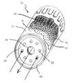
- FIG. 1is a perspective view, partially cut away, of an oil filter in accordance with a first embodiment of the present invention
- FIG. 2is a cross-sectional view of the filter of FIG. 1;
- FIG. 3Ais a side plan view of an additive dispensing module, which is a component of the oil filter of FIGS. 1-2;
- FIG. 3Bis a cross-sectional view of the additive-dispensing module of FIG. 3A;
- FIG. 4is a cross-sectional view of an oil filter according to a second embodiment of the present invention.
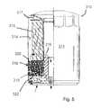
- FIG. 5is a cross-sectional view of an oil filter according to a third embodiment of the present invention.
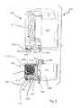
- FIG. 6is an exploded cross-sectional view of a two-part oil filter assembly according to a fourth embodiment of the present invention.
- FIG. 7is a simplified top plan view of a supplemental cartridge, which is a component of the assembly of FIG. 6 .
- FIGS. 1 and 2there is shown an oil filter 10 according to a first preferred embodiment of this invention.
- the direction of oil flow, through the filter 10is shown by the arrows in FIG. 2, which illustrate a flow path through the filter.
- the oil filter 10generally includes a hollow cylindrical housing 11 which defines a chamber 14 therein, a porous mechanically active filter element 15 within that chamber, and a chemically active filter element 16 , made up of a plurality of individual composite additive-dispensing modules 18 , also retained within the chamber inside the housing.
- a foraminous cylindrical screen or support frame 17may, optionally, be provided within the housing 11 to supportively hold the filter elements 15 , 16 therein.
- a grommet 19 or other internal sealing memberis provided centrally at the base of the frame 17 to route the oil along the flow path and through the filter elements 15 , 16 .
- the grommet 19may include a flexibly resilient sealing member having an integral pressure relief valve therein, such as that disclosed in U.S. Pat. No. 6,214,215, the disclosure of which is incorporated by reference.
- the oil filter 10may incorporate a spring-loaded or other conventional pressure relief valve of a type known to those in the art.
- a base plate 20 of the housing 11includes a plurality of inlet ports 22 formed therethrough and arranged in a circular pattern.
- the base plate 20also includes a central outlet port 24 .
- the outlet port 24has a plurality of female threads formed therein to allow rotatable mounting of the filter 10 on an externally threaded hollow tubular fitting on an engine block (not shown).
- An annular external seal or gasket 25fits engagingly into a groove 26 formed at the bottom surface of the base plate, to resist oil leakage outwardly from the base of the filter.
- the mechanically active filter element 15is a conventional cylindrical member made of accordion-pleated filter paper.
- the chemically active filter element 16is also provided in the general shape of a cylinder, and is disposed radially and coaxially within the mechanically active filter element 15 .
- the chemically active filter element 16is located inside of, and therefore downstream of the mechanical filter element 15 , in order to allow a mechanical filtration to take place before the chemical reaction of unwanted contaminants from the oil with the beneficial additive composition of the chemical filter element 16 .
- Placement of the chemical filter element 16 between the mechanically active filter element 15 and the frame member 17puts it downstream in the flow path from the mechanical filter element, yet still obtains the maximum possible support from the frame member 17 . This may be helpful where the chemical filter element 16 is made up of a plurality of separate and unconnected individual modules 18 .
- the individual additive-dispensing modules 18 making up the chemically active filter element 16may be bonded together or otherwise cohesively associated with one another to form a substantially integral, yet highly porous filter element 16 capable of independent self-support.
- the additive-dispensing modules 18 making up the chemically active filter element 16are an important feature of the filter 10 hereof.
- the additive-dispensing modules 18are made of a combination of materials. Referring now to FIGS. 3A and 3B, a representative additive-dispensing module 18 is shown.
- the module 18includes a module housing in the form of a hollow shell 23 , which is preferably formed from a ceramic or polymeric material.
- the housing shell 23includes a relatively thin wall 31 having a plurality of apertures 27 formed therethrough, to allow diffusion of a beneficial additive composition 33 outwardly therefrom.
- a beneficial additive composition 33Disposed within the interior of the housing shell 23 is a beneficial additive composition 33 , which includes one or more additives which may be selected from the group including basic conditioners, corrosion inhibitors, metal deactivators, antioxidants, dispersants, friction modifiers, oil stabilizers, pour point depressants, detergents, viscosity index improvers, anti-wear agents, extreme pressure additives, mixtures of the above additives, and/or other known beneficial additives.
- additiveswhich may be selected from the group including basic conditioners, corrosion inhibitors, metal deactivators, antioxidants, dispersants, friction modifiers, oil stabilizers, pour point depressants, detergents, viscosity index improvers, anti-wear agents, extreme pressure additives, mixtures of the above additives, and/or other known beneficial additives.
- the additive composition 33is preferably injected into the housing shell 23 in a hot liquid state, and solidifies as it cools.
- the additive composition 33may be added in powder form, or may be dispersed in a grease or in a wax.
- the additive composition 33is preferred to be at least partially soluble in hot engine oil.
- the additive-dispensing module 18may have a porous or semiporous membrane 35 covering and surrounding the housing shell 23 .
- the membrane 35where used, is preferred to be formed of a polymeric material, which may be selected from polysulfones, waxes, polymethylene pentene, or other suitable permeable or semi-permeable material.
- the material selected for the membrane 35can be stable in a hot oil environment, or may be a material which will erode over time in a hot oil environment.
- the membrane 35allows the beneficial additive composition 33 to be slowly released into the oil from the additive-dispensing module 18 , thereby conditioning the oil in a metered manner over time.
- the basic conditioner of the additive-dispensing modulesis preferably a basic salt selected from the group consisting of calcium carbonate, potassium carbonate, potassium bicarbonate, aluminum dihydroxy sodium carbonate, magnesium oxide, magnesium carbonate, zinc oxide, sodium bicarbonate, sodium hydroxide, calcium hydroxide, potassium hydroxide, and mixtures thereof.
- the additive-dispensing modulesmay be bonded together or otherwise connected together to form a substantially integral, yet perforated and highly porous chemical filter element 16 .
- the frame member 17is not needed, and may be omitted if desired.
- the basic salt component of the additive 33acts to counteract and neutralize acidic combustion products. This neutralization of acidic combustion products allows for a much longer useful life of some other oil additives such as, for example, dispersants and zinc dialkyldithiophosphate (ZDP), which are provided in the oil by the manufacturer thereof. This, in turn, allows for greater intervals between oil changes than is possible without the chemically active filter element.
- ZDPzinc dialkyldithiophosphate
- the oil filter 210 in this embodimentgenerally includes a cylindrical housing 211 which defines a hollow space 214 therein, a porous mechanically active filter element 215 within that space, and a chemically active filter element 216 , made up of a plurality of individual composite additive-dispensing modules 218 , also retained within the hollow space inside the housing and disposed within the mechanically active filter element.
- the additive-dispensing modules 218are substantially identical to the additive-dispensing modules 18 , as described in connection with the first embodiment 10 .
- the individual additive-dispensing modules 218 making up the chemically active filter element 216may be bonded together or otherwise cohesively associated with one another to form a substantially integral, yet highly porous filter element 216 capable of independently supporting itself.
- the oil filter 210is substantially identical to the oil filter 10 of the first embodiment, as described hereinabove.
- the mechanically active filter element 215is a conventional cylindrical member made of accordion-pleated filter paper.
- the chemically active filter element 216is also provided in the shape of a cylinder in this embodiment, and is disposed radially and coaxially outside of the mechanically active filter element 215 .
- a foraminous cylindrical screen or support frame 217may, optionally, be provided within the housing 211 to supportively hold the filter elements 215 , 216 therein.
- the chemically active filter element 216is located outside of, and therefore upstream of the mechanical filter element 215 , in order to allow chemical modification of acids or other unwanted contaminants which may be present in the oil, with the additive composition of the chemical filter element 216 , prior to mechanical filtration.
- the top and bottom horizontal segments 220 , 222 of the frame member 217have been extended outwardly towards the outer wall of the housing 211 , as compared to the frame member 17 from the first embodiment, to contain the additive-dispensing modules 218 of the chemically active filter element therebetween.
- the portion of the frame member bottom horizontal segment 222 below the chemical filter element 216is made foraminous, as shown, to allow oil to flow freely therethrough.
- the vertical inner wall 224 of the frame member 217is also necessarily foraminous to allow oil flow therethrough.
- an oil filter 310 in accordance with a third embodiment of the present inventionis shown.
- the oil filter 310is substantially,identical to the oil filter 10 of the first embodiment, as described hereinabove.
- the oil filter 310 in this embodimentgenerally includes a hollow cylindrical housing 311 which defines a chamber 314 therein, a porous mechanically active filter element 315 within that chamber, and a chemically active filter element 316 , made up of a plurality of individual composite additive-dispensing modules 318 , also retained within the chamber inside the housing and disposed below and before the mechanically active filter element.
- the additive-dispensing modules 318are substantially identical to the additive-dispensing modules 18 , as described in connection with the first embodiment 10 .
- the individual additive-dispensing modules 318 making up the chemically active filter element 316may be bonded together or otherwise cohesively associated with one another to form a substantially integral, yet highly porous filter element 316 capable of independently supporting itself.
- the mechanically active filter element 315is a conventional cylindrical member made of accordion-pleated filter paper.
- a selectively foraminous cylindrical screen or support frame 317may, optionally, be provided within the housing 311 to supportively hold the mechanically active filter element 315 therein.
- porous annular upper and lower foraminous dividers 320 , 322may be placed above and/or below the chemically active filter element 316 to retain the additive-dispensing modules 318 of the chemically active filter element therebetween.
- the dividers 320 and/or 322where used, may be selectively foraminous solid plates or may be mesh screens.
- the upper divider 320is constructed and arranged to pass oil only to the outside surface of the mechanically active filter element 315 , so that the oil must be mechanically filtered before exiting the filter 310 .
- the chemically active filter element 316is also provided in the shape of a flattened cylinder in this embodiment, and is disposed below the mechanically active filter element 315 .
- the chemically active filter element 316is located below the mechanical filter element 315 , and therefore precedes the mechanical filter element in the flow path, in order to allow chemical modification of acids or other unwanted contaminants which may be present in the oil, with the beneficial additive composition of the chemically active filter element 316 , prior to mechanical filtration.
- a central sealing member 319is also provided and is similar to the grommet 19 as previously described in connection with the first embodiment.
- This designensures that the oil will pass completely through the chemically active filter element before it reaches the mechanically active filter element, and provides more and longer-lasting interaction between the oil and the chemically active filter element than the design of FIG. 4 .
- the oil filter assembly 410 in this embodimentincludes two primary parts, a conventional oil filter 402 shown on top in the drawing, and a supplemental cartridge 404 , shown below the conventional filter.
- the conventional oil filter 402incorporates a mechanically active filter element 415 within a cylindrical housing 411 .
- the conventional oil filter 402further includes a base plate 420 , which includes a plurality of inlet ports 422 arranged in a circular pattern as well as a central outlet port 424 .
- the base plate 420is provided as an integral part of the cylindrical housing 411 , and an annular sealing member 425 fits engagingly into a groove 426 formed at the bottom surface of the base plate.
- the outlet port 424has a plurality of female threads formed therein to allow rotatable mounting of the filter 402 on an externally threaded hollow tubular male connector fitting 409 of the supplemental cartridge 404 .
- the supplemental cartridge 404is made to rotatably and threadably attach to an externally threaded hollow tubular fitting on an engine block (not shown), and to then have the conventional filter 402 rotatably and threadably fit thereon.
- the supplemental cartridge 404includes a cylindrical housing 405 having a side wall 406 , a base plate 407 , sealably connected to the bottom edge of the side wall, and a cover plate 408 sealably connected to the top edge of the side wall.
- the cover plate 408has a plurality of outlet openings 412 formed therein above the chemically active filter member 416 to allow oil to flow outwardly from the supplemental cartridge 404 and then into the inlets 422 of the conventional oil filter 402 .
- the base plate 407 of the supplemental cartridge 404includes a plurality of inlet ports 432 , arranged in a circular pattern, as well as a central outlet port 434 .
- the base plate 407is provided as an integral part of the cylindrical housing 405 , and an annular sealing member 435 fits engagingly into a groove 436 formed at the bottom surface of the base plate.
- the outlet port 434has a plurality of female threads formed therein to allow rotatable mounting of the supplemental cartridge 404 to an externally threaded hollow tubular fitting on an engine block (not shown)
- the hollow tubular male connector fitting 409which is externally threaded, is provided at the center of the cover plate 408 , and a cylindrical dividing wall member 403 is centrally disposed within the cartridge housing 405 , and forms a fluid seal at the top and bottom surfaces thereof.
- the cylindrical dividing wall member 403is preferably made of an oil-tolerant elastomer.
- the supplemental cartridge 404contains a chemically active filter element 416 therein.
- the chemically active filter element 416is made up of a plurality of individual composite additive-dispensing modules 418 , retained within the hollow space inside the cartridge housing 405 and disposed radially outside of the cylindrical dividing wall member 403 .
- the additive-dispensing modules 418are substantially identical to the additive-dispensing modules 18 , as described in connection with the first embodiment 10 .
- the individual additive-dispensing modules 418 making up the chemically active filter element 416may be bonded together or otherwise cohesively associated with one another to form a substantially integral, yet highly porous filter element capable of independently supporting itself.
- a porous, annular lower mesh screen 419may be placed below the chemically active filter element 416 to retain the additive-dispensing modules 418 of the chemically active filter element thereabove.
- the mesh screen 419may rest on a transverse horizontal flange 429 , which is an integral part of the cylindrical dividing wall member 403 .
- the total assembly 410functions in a manner similar to the oil filter 310 of FIG. 5 .
- the chemically active filter element 416is also provided in the shape of a cylinder in this embodiment, and when the entire assembly 410 is considered as a whole, the chemically active filter element is disposed below the mechanically active filter element 415 of the conventional oil filter 402 , and therefore precedes the mechanical filter element in the flow path, in order to allow chemical modification of acids or other unwanted contaminants which may be present in the oil, with the beneficial additive composition of the chemically active filter element 416 , prior to mechanical filtration.
- This designensures that the oil will pass completely through the chemically active filter element 416 before it reaches the mechanically active filter element 415 , and provides more and longer-lasting interaction between the oil and the chemically active filter element than the design of FIG. 4 .
- the supplemental cartridge 404may include a pair of hollow tubes 437 , 438 attached to the side wall 406 thereof, which communicate with the interior of the cartridge housing 405 .
- these tubes 437 , 438are provided to allow connection of the supplemental cartridge to a heat exchanger 440 to allow cooling of the oil which passes therethrough.
Landscapes
- Chemical & Material Sciences (AREA)
- Chemical Kinetics & Catalysis (AREA)
- Organic Chemistry (AREA)
- Combustion & Propulsion (AREA)
- General Chemical & Material Sciences (AREA)
- Oil, Petroleum & Natural Gas (AREA)
- Engineering & Computer Science (AREA)
- Lubrication Details And Ventilation Of Internal Combustion Engines (AREA)
- Filtration Of Liquid (AREA)
- Fats And Perfumes (AREA)
- Lubrication Of Internal Combustion Engines (AREA)
- Filtering Materials (AREA)
- Lubricants (AREA)
Abstract
Description
Claims (14)
Priority Applications (12)
| Application Number | Priority Date | Filing Date | Title |
|---|---|---|---|
| US10/233,852US6623636B2 (en) | 2000-05-08 | 2002-08-30 | Staged oil filter incorporating timed release oil conditioner |
| AT03791881TATE330683T1 (en) | 2002-08-30 | 2003-08-28 | MULTI-STAGE OIL FILTER WITH TIMED RELEASE OIL CONDITIONER |
| EP03791881AEP1545736B1 (en) | 2002-08-30 | 2003-08-28 | Staged oil filter incorporating timed release oil conditioner |
| DE60306401TDE60306401T2 (en) | 2002-08-30 | 2003-08-28 | MULTI-STAGE OIL FILTER WITH OIL CONDITIONER WITH TIMELINE DISTRIBUTION |
| PCT/US2003/026921WO2004020070A1 (en) | 2002-08-30 | 2003-08-28 | Staged oil filter incorporating timed release oil conditioner |
| AU2003265800AAU2003265800A1 (en) | 2002-08-30 | 2003-08-28 | Staged oil filter incorporating timed release oil conditioner |
| CA002497131ACA2497131A1 (en) | 2002-08-30 | 2003-08-28 | Staged oil filter incorporating timed release oil conditioner |
| BR0313884-4ABR0313884A (en) | 2002-08-30 | 2003-08-28 | Oil filter, and supplement cartridge for use in combination with an oil filter |
| JP2004531611AJP2005537416A (en) | 2002-08-30 | 2003-08-28 | Stage oil filter with built-in oil regulator |
| CNB038245701ACN100337713C (en) | 2002-08-30 | 2003-08-28 | Staged oil filter with timed release oil regulator |
| MXPA05002335AMXPA05002335A (en) | 2002-08-30 | 2003-08-28 | Staged oil filter incorporating timed release oil conditioner. |
| ZA200502165AZA200502165B (en) | 2002-08-30 | 2005-03-15 | Staged oil filter incorporating tinmed release oilconditioner |
Applications Claiming Priority (2)
| Application Number | Priority Date | Filing Date | Title |
|---|---|---|---|
| US56603400A | 2000-05-08 | 2000-05-08 | |
| US10/233,852US6623636B2 (en) | 2000-05-08 | 2002-08-30 | Staged oil filter incorporating timed release oil conditioner |
Related Parent Applications (1)
| Application Number | Title | Priority Date | Filing Date |
|---|---|---|---|
| US56603400AContinuation-In-Part | 2000-05-08 | 2000-05-08 |
Publications (2)
| Publication Number | Publication Date |
|---|---|
| US20020195384A1 US20020195384A1 (en) | 2002-12-26 |
| US6623636B2true US6623636B2 (en) | 2003-09-23 |
Family
ID=31977307
Family Applications (1)
| Application Number | Title | Priority Date | Filing Date |
|---|---|---|---|
| US10/233,852Expired - LifetimeUS6623636B2 (en) | 2000-05-08 | 2002-08-30 | Staged oil filter incorporating timed release oil conditioner |
Country Status (12)
| Country | Link |
|---|---|
| US (1) | US6623636B2 (en) |
| EP (1) | EP1545736B1 (en) |
| JP (1) | JP2005537416A (en) |
| CN (1) | CN100337713C (en) |
| AT (1) | ATE330683T1 (en) |
| AU (1) | AU2003265800A1 (en) |
| BR (1) | BR0313884A (en) |
| CA (1) | CA2497131A1 (en) |
| DE (1) | DE60306401T2 (en) |
| MX (1) | MXPA05002335A (en) |
| WO (1) | WO2004020070A1 (en) |
| ZA (1) | ZA200502165B (en) |
Cited By (37)
| Publication number | Priority date | Publication date | Assignee | Title |
|---|---|---|---|---|
| US20050194301A1 (en)* | 2004-03-05 | 2005-09-08 | Hacker John R. | Liquid filter assembly for use with treatment agent; and, methods |
| US20060260874A1 (en)* | 2005-05-20 | 2006-11-23 | Lockledge Scott P | Materials and processes for reducing combustion by-products in a lubrication system for an internal combustion engine |
| US20070170107A1 (en)* | 2005-07-18 | 2007-07-26 | Zafar Hussain | Single body fuIl flow acid-neutralizing fluid filter |
| US20070235378A1 (en)* | 2004-03-05 | 2007-10-11 | Donaldson Corporation Company, Inc. | Top Load Liquid Filter Assembly for Use with Treatment Agent; and, Methods |
| US20080047887A1 (en)* | 2006-08-28 | 2008-02-28 | Gerwin Weston H | Additive dispersing filter and method of making |
| US20080110819A1 (en)* | 2000-05-08 | 2008-05-15 | Ronald Paul Rohrbach | Staged oil filter incorporating additive-releasing particles |
| US20080190504A1 (en)* | 2007-02-13 | 2008-08-14 | Bilski Gerard W | Additive dispersing filter and method of making |
| US20090050547A1 (en)* | 2007-06-14 | 2009-02-26 | Hsu Jeffery Hsiu | Additive Releasing Oil Filter |
| US20090194484A1 (en)* | 2008-02-01 | 2009-08-06 | Lutek, Llc | Oil Filters Containing Strong Base and Methods of Their Use |
| US7625419B2 (en) | 2006-05-10 | 2009-12-01 | Donaldson Company, Inc. | Air filter arrangement; assembly; and, methods |
| US20110163047A1 (en)* | 2008-02-13 | 2011-07-07 | Bilski Gerard W | Additive dispersing filter and method |
| US8034145B2 (en) | 2004-06-14 | 2011-10-11 | Donaldson Company, Inc. | Air filter arrangement; assembly; and, methods |
| US20120144855A1 (en)* | 2010-12-11 | 2012-06-14 | Andrew Reinhard Krause | Modular water filter assembly |
| US8277532B2 (en) | 2004-08-06 | 2012-10-02 | Donaldson Company, Inc. | Air filter arrangement; assembly; and methods |
| US8292983B2 (en) | 2005-01-13 | 2012-10-23 | Donaldson Company, Inc. | Air filter cartridge and air cleaner assembly |
| US8496723B2 (en) | 2005-01-13 | 2013-07-30 | Donaldson Company, Inc. | Air filter arrangement |
| US20140014561A1 (en)* | 2012-07-10 | 2014-01-16 | Southern Taiwan University Of Science And Technology | Porous Magnetic Filter Having Sensor |
| US9320997B2 (en) | 2013-06-28 | 2016-04-26 | Donaldson Company, Inc. | Air filter cartridges; air cleaner assemblies; housings; features; components; and, methods |
| US9539531B2 (en) | 2007-02-13 | 2017-01-10 | Fram Group IP, LLC | Additive dispersing filter and method |
| US9555370B2 (en) | 2007-09-07 | 2017-01-31 | Donaldson Company, Inc. | Air filter assembly; components thereof; and, methods |
| US9623350B2 (en) | 2013-03-01 | 2017-04-18 | Fram Group Ip Llc | Extended-life oil management system and method of using same |
| US9623351B2 (en) | 2009-04-09 | 2017-04-18 | Cummins Filtration Ip, Inc. | Filtration sealing system |
| US10005014B2 (en) | 2012-01-30 | 2018-06-26 | Fram Group Ip Llc | Additive carrier for spin on filters |
| US10434454B2 (en) | 2011-06-30 | 2019-10-08 | Donaldson Company, Inc. | Filter cartridge |
| US10823072B2 (en) | 2018-04-02 | 2020-11-03 | Raytheon Technologies Corporation | Passive fuel additives dosing system |
| US11020698B2 (en) | 2015-12-11 | 2021-06-01 | Cummins Filtration Ip, Inc. | Filter with variable cross-section axial seal |
| US11110382B2 (en) | 2014-12-27 | 2021-09-07 | Donaldson Company, Inc. | Filter cartridges; air cleaner assemblies; housings; features; components; and, methods |
| US11141687B2 (en) | 2016-05-02 | 2021-10-12 | Cummins Filtration Ip, Inc. | Filter with interlocking housing interface |
| US11167234B2 (en) | 2016-03-18 | 2021-11-09 | Cummins Filtration Ip, Inc. | Interlocked stable filter assembly |
| US11193420B2 (en)* | 2018-11-16 | 2021-12-07 | United Technologies Corporation | System and method for monitoring fuel additives |
| US11198082B2 (en) | 2017-08-31 | 2021-12-14 | Donaldson Company, Inc. | Filter cartridges; air cleaner assemblies; housings; features; components; and methods |
| US11235275B2 (en) | 2017-03-16 | 2022-02-01 | Cummins Filtration Ip, Inc. | Filtration sealing system |
| US11298640B2 (en) | 2017-01-25 | 2022-04-12 | Cummins Filtration Ip, Inc. | Expandable threaded adaptor for threadless shell |
| US11724220B2 (en) | 2017-02-21 | 2023-08-15 | Cummins Filtration Ip, Inc. | Undulated interlocking housing-endplate interface geometry |
| US11772026B2 (en) | 2014-09-15 | 2023-10-03 | Donaldson Company, Inc. | Filter cartridges; air cleaner assemblies; housings; features; components; and, methods |
| CN117379832A (en)* | 2023-12-04 | 2024-01-12 | 山西鑫海环境治理股份有限公司 | Extraction purification device that used lubricating oil regeneration production used |
| US12263428B2 (en) | 2018-07-23 | 2025-04-01 | Cummins Filtration Sarl | Radial seal for spin-on filter |
Families Citing this family (25)
| Publication number | Priority date | Publication date | Assignee | Title |
|---|---|---|---|---|
| US7297267B2 (en)* | 2003-03-11 | 2007-11-20 | Parker-Hannifin Corporation | Oil-sorbing filter element |
| US7000655B2 (en) | 2004-01-09 | 2006-02-21 | The Lubrizol Corporation | Fluid additive delivery systems |
| US7713425B2 (en) | 2005-05-11 | 2010-05-11 | Honeywell International Inc. | Oil management system |
| US7473355B2 (en) | 2005-11-15 | 2009-01-06 | Purolator Filters Na Llc | Chemical additive carrier for filter |
| US20080302709A1 (en)* | 2005-11-28 | 2008-12-11 | Adrian Colin Jefferies | Method for Monitoring the Degree of Clogging of the Filtration Surface of an Oil Filter |
| WO2007089852A2 (en)* | 2006-01-30 | 2007-08-09 | Donaldson Company, Inc. | Filter arrangement and servicing thereof |
| JP3136158U (en)* | 2006-09-05 | 2007-10-18 | 株式会社Jcd | Cartridge type oil filter and engine cleaning device |
| US8022021B2 (en)* | 2007-02-05 | 2011-09-20 | The Lubrizol Corporation | Low ash controlled release gels |
| US20090101561A1 (en) | 2007-10-19 | 2009-04-23 | The Lubrizol Corporation | Filter Cap Additive Delivery System |
| CN102808674A (en)* | 2011-06-03 | 2012-12-05 | 深圳职业技术学院 | Oil filter |
| CN102943701A (en)* | 2011-08-15 | 2013-02-27 | 深圳职业技术学院 | Chemical engine oil filter |
| SE536057C2 (en)* | 2011-08-25 | 2013-04-16 | Scania Cv Ab | Device comprising cation exchanger for reducing the acidity of engine oil and engine with such device |
| JP5639615B2 (en) | 2011-11-07 | 2014-12-10 | トヨタ紡織株式会社 | Oil deterioration control device |
| JP5677268B2 (en) | 2011-11-07 | 2015-02-25 | トヨタ紡織株式会社 | Oil deterioration control device |
| JP5798498B2 (en)* | 2012-01-23 | 2015-10-21 | トヨタ自動車株式会社 | Oil filter |
| CN104024587A (en)* | 2012-02-06 | 2014-09-03 | 康明斯过滤Ip公司 | Lubricant oil filter with continuous release additive vessel |
| JP6057541B2 (en) | 2012-05-07 | 2017-01-11 | トヨタ紡織株式会社 | Oil deterioration control device |
| CN103742225A (en)* | 2013-12-25 | 2014-04-23 | 柳州正菱集团有限公司 | Filter cartridge for engine oil filter |
| EP3137190B1 (en)* | 2014-04-30 | 2020-08-26 | K & N Engineering, Inc. | Air filter with oil formulation |
| CN104406035A (en)* | 2014-12-05 | 2015-03-11 | 山东蓬翔汽车有限公司 | External lubricating oil filter |
| CN104593136A (en)* | 2015-01-30 | 2015-05-06 | 西安热工研究院有限公司 | Regenerative filter element having automatic additive adding function and automatic adding method |
| CN109554215A (en)* | 2018-03-30 | 2019-04-02 | 杨青林 | Lubricating oil synergistic device |
| US11173438B2 (en)* | 2018-09-14 | 2021-11-16 | Caterpillar Inc. | Filter having tracer material |
| IL272387B1 (en)* | 2020-01-30 | 2023-11-01 | Cohen Shemon | Device and method for supplying cold and hot water |
| DE102020129849A1 (en) | 2020-11-12 | 2022-05-12 | Bwt Holding Gmbh | Device and method for protecting drinking water from microorganisms |
Citations (2)
| Publication number | Priority date | Publication date | Assignee | Title |
|---|---|---|---|---|
| US4144166A (en)* | 1977-03-24 | 1979-03-13 | Atlantic Richfield Company | Compositions, apparatus and methods useful for releasing solid lubricating oil additive |
| US5725031A (en)* | 1996-08-01 | 1998-03-10 | Alliedsignal Inc. | Method for introducing PTFE into a spin-on oil filter |
Family Cites Families (14)
| Publication number | Priority date | Publication date | Assignee | Title |
|---|---|---|---|---|
| JPS53117849U (en)* | 1976-09-09 | 1978-09-19 | ||
| US5069799A (en)* | 1989-09-07 | 1991-12-03 | Exxon Research & Engineering Company | Method for rejuvenating lubricating oils |
| KR960702887A (en)* | 1994-04-06 | 1996-05-23 | 신지 마키노 | FUEL TREATMENT DEVICE |
| US5591330A (en)* | 1994-05-25 | 1997-01-07 | T/F Purifiner, Inc. | Oil filter containing an oil soluble thermoplastic additive material therein |
| FR2725558B1 (en)* | 1994-10-10 | 1996-10-31 | Commissariat Energie Atomique | METHOD FOR FORMING HOLES IN A PHOTOSENSITIVE RESIN LAYER APPLICATION TO THE MANUFACTURE OF MICROPOINT EMISSIVE CATHODE ELECTRON SOURCES AND FLAT DISPLAY SCREENS |
| JPH09141011A (en)* | 1995-11-16 | 1997-06-03 | Wako Sangyo Kk | Fluid filter and engine oil filtering device using the same |
| US5662799A (en)* | 1996-06-21 | 1997-09-02 | Fleetguard, Inc. | Slow release coolant filter |
| US5741433A (en)* | 1996-06-21 | 1998-04-21 | Betzdearborn Inc. | Controlled release supplemental coolant additive |
| US5718258A (en)* | 1996-10-22 | 1998-02-17 | T/F Purifiner, Inc. | Releasing additives into engine oil |
| JPH1122442A (en)* | 1997-07-03 | 1999-01-26 | Toyota Motor Corp | Engine oil deterioration inhibitor and engine oil deterioration prevention device |
| US5803024A (en)* | 1997-07-18 | 1998-09-08 | Baldwin Filters, Inc. | Coolant filter having a delayed release supplemental coolant additive cartridge |
| US6238554B1 (en)* | 1999-06-16 | 2001-05-29 | Fleetguard, Inc. | Fuel filter including slow release additive |
| US6379564B1 (en)* | 2000-05-08 | 2002-04-30 | Ronald Paul Rohrbach | Multi-stage fluid filter, and methods of making and using same |
| EP1284801A2 (en)* | 2000-05-08 | 2003-02-26 | Honeywell International Inc. | Staged oil filter incorporating pelletized basic conditioner |
- 2002
- 2002-08-30USUS10/233,852patent/US6623636B2/ennot_activeExpired - Lifetime
- 2003
- 2003-08-28WOPCT/US2003/026921patent/WO2004020070A1/enactiveIP Right Grant
- 2003-08-28EPEP03791881Apatent/EP1545736B1/ennot_activeExpired - Lifetime
- 2003-08-28MXMXPA05002335Apatent/MXPA05002335A/enactiveIP Right Grant
- 2003-08-28BRBR0313884-4Apatent/BR0313884A/ennot_activeApplication Discontinuation
- 2003-08-28CNCNB038245701Apatent/CN100337713C/ennot_activeExpired - Fee Related
- 2003-08-28JPJP2004531611Apatent/JP2005537416A/enactivePending
- 2003-08-28CACA002497131Apatent/CA2497131A1/ennot_activeAbandoned
- 2003-08-28DEDE60306401Tpatent/DE60306401T2/ennot_activeExpired - Lifetime
- 2003-08-28AUAU2003265800Apatent/AU2003265800A1/ennot_activeAbandoned
- 2003-08-28ATAT03791881Tpatent/ATE330683T1/ennot_activeIP Right Cessation
- 2005
- 2005-03-15ZAZA200502165Apatent/ZA200502165B/enunknown
Patent Citations (2)
| Publication number | Priority date | Publication date | Assignee | Title |
|---|---|---|---|---|
| US4144166A (en)* | 1977-03-24 | 1979-03-13 | Atlantic Richfield Company | Compositions, apparatus and methods useful for releasing solid lubricating oil additive |
| US5725031A (en)* | 1996-08-01 | 1998-03-10 | Alliedsignal Inc. | Method for introducing PTFE into a spin-on oil filter |
Cited By (98)
| Publication number | Priority date | Publication date | Assignee | Title |
|---|---|---|---|---|
| US20080110819A1 (en)* | 2000-05-08 | 2008-05-15 | Ronald Paul Rohrbach | Staged oil filter incorporating additive-releasing particles |
| US7238285B2 (en) | 2004-03-05 | 2007-07-03 | Donaldson Company, Inc. | Liquid filter assembly for use with treatment agent; and, methods |
| US20050194301A1 (en)* | 2004-03-05 | 2005-09-08 | Hacker John R. | Liquid filter assembly for use with treatment agent; and, methods |
| US7160451B2 (en) | 2004-03-05 | 2007-01-09 | Donaldson Company, Inc. | Liquid filter assembly for use with treatment agent and methods |
| US20070235378A1 (en)* | 2004-03-05 | 2007-10-11 | Donaldson Corporation Company, Inc. | Top Load Liquid Filter Assembly for Use with Treatment Agent; and, Methods |
| US10603618B2 (en) | 2004-06-14 | 2020-03-31 | Donaldson Company, Inc. | Air filter arrangement; assembly; and, methods |
| US9937455B2 (en) | 2004-06-14 | 2018-04-10 | Donaldson Company, Inc. | Air filter arrangement; assembly; and, methods |
| US8034145B2 (en) | 2004-06-14 | 2011-10-11 | Donaldson Company, Inc. | Air filter arrangement; assembly; and, methods |
| US11291943B2 (en) | 2004-06-14 | 2022-04-05 | Donaldson Company, Inc. | Air filter arrangement; assembly; and, methods |
| US8480779B2 (en)* | 2004-06-14 | 2013-07-09 | Donaldson Company, Inc. | Air filter arrangement; assembly; and, methods |
| US9120047B2 (en) | 2004-06-14 | 2015-09-01 | Donaldson Company, Inc. | Air filter arrangement; assembly; and, methods |
| US9795911B2 (en) | 2004-08-06 | 2017-10-24 | Donaldson Company, Inc. | Air filter arrangement; assembly; and, methods |
| US11759744B2 (en) | 2004-08-06 | 2023-09-19 | Donaldson Company, Inc. | Air filter arrangement; assembly; and, methods |
| US8277532B2 (en) | 2004-08-06 | 2012-10-02 | Donaldson Company, Inc. | Air filter arrangement; assembly; and methods |
| US10556201B2 (en) | 2004-08-06 | 2020-02-11 | Donaldson Company, Inc. | Air filter arrangement; assembly; and, methods |
| US8906128B2 (en) | 2004-08-06 | 2014-12-09 | Donaldson Company, Inc. | Air filter arrangement; assembly; and, methods |
| US11207632B2 (en) | 2004-08-06 | 2021-12-28 | Donaldson Company, Inc. | Air filter arrangement; assembly; and, methods |
| US10864475B2 (en) | 2005-01-13 | 2020-12-15 | Donaldson Company, Inc. | Air filter arrangement; assembly; and, methods |
| US12070711B2 (en) | 2005-01-13 | 2024-08-27 | Donaldson Company, Inc. | Air filter arrangement; assembly; and, methods |
| US11020699B2 (en) | 2005-01-13 | 2021-06-01 | Donaldson Company, Inc. | Air filter arrangement; assembly; and, methods |
| US9527023B2 (en) | 2005-01-13 | 2016-12-27 | Donaldson Comapny, Inc. | Air filter arrangement; assembly; and, methods |
| US8709119B2 (en) | 2005-01-13 | 2014-04-29 | Donaldson Company, Inc. | Air filter cartridge and air cleaner assembly |
| US12138574B2 (en) | 2005-01-13 | 2024-11-12 | Donaldson Company, Inc. | Air Filter Arrangement; Assembly; and, Methods |
| US11826689B2 (en) | 2005-01-13 | 2023-11-28 | Donaldson Company, Inc. | Air filter arrangement; assembly; and, methods |
| US10421034B2 (en) | 2005-01-13 | 2019-09-24 | Donaldson Company, Inc. | Air filter arrangement; assembly; and, methods |
| US11951429B2 (en) | 2005-01-13 | 2024-04-09 | Donaldson Company, Inc. | Air filter arrangement; assembly; and, methods |
| US8292983B2 (en) | 2005-01-13 | 2012-10-23 | Donaldson Company, Inc. | Air filter cartridge and air cleaner assembly |
| US10315144B2 (en) | 2005-01-13 | 2019-06-11 | Donaldson Company, Inc. | Air filter arrangement; assembly; and, methods |
| US9180399B2 (en) | 2005-01-13 | 2015-11-10 | Donaldson Company, Inc. | Air filter arrangement |
| US8496723B2 (en) | 2005-01-13 | 2013-07-30 | Donaldson Company, Inc. | Air filter arrangement |
| US8636820B2 (en) | 2005-01-13 | 2014-01-28 | Donaldson Company, Inc. | Air filter arrangement |
| US10065145B2 (en) | 2005-01-13 | 2018-09-04 | Donaldson Company, Inc. | Air filter arrangement; assembly; and, methods |
| US8607991B2 (en) | 2005-05-20 | 2013-12-17 | Lutek, Llc | Materials and processes for reducing combustion by-products in a lubrication system for an internal combustion engine |
| US7520371B2 (en) | 2005-05-20 | 2009-04-21 | Lutek, Llc | Materials and processes for reducing combustion by-products in a lubrication system for an internal combustion engine |
| US20090139483A1 (en)* | 2005-05-20 | 2009-06-04 | Lutek, Llc | Materials and processes for reducing combustion by-products in a lubrication system for an internal combustion engine |
| US20060261004A1 (en)* | 2005-05-20 | 2006-11-23 | Lockledge Scott P | Materials, filters, and systems for immobilizing combustion by-products and controlling lubricant viscosity |
| US8016125B2 (en) | 2005-05-20 | 2011-09-13 | Lutek, Llc | Materials, filters, and systems for immobilizing combustion by-products and controlling lubricant viscosity |
| US20060260874A1 (en)* | 2005-05-20 | 2006-11-23 | Lockledge Scott P | Materials and processes for reducing combustion by-products in a lubrication system for an internal combustion engine |
| US20070170107A1 (en)* | 2005-07-18 | 2007-07-26 | Zafar Hussain | Single body fuIl flow acid-neutralizing fluid filter |
| US8062399B2 (en) | 2006-05-10 | 2011-11-22 | Donaldson Company, Inc. | Air filter arrangement; assembly; and, methods |
| US7625419B2 (en) | 2006-05-10 | 2009-12-01 | Donaldson Company, Inc. | Air filter arrangement; assembly; and, methods |
| US8328897B2 (en) | 2006-05-10 | 2012-12-11 | Donaldson Company, Inc. | Air cleaner arrangement; assembly; and, methods |
| WO2008027892A3 (en)* | 2006-08-28 | 2008-06-26 | Honeywell Int Inc | Additive dispersing filter and method of making |
| US7481923B2 (en) | 2006-08-28 | 2009-01-27 | Honeywell International Inc. | Additive dispersing filter and method of making |
| US20080047887A1 (en)* | 2006-08-28 | 2008-02-28 | Gerwin Weston H | Additive dispersing filter and method of making |
| US8658047B2 (en) | 2007-02-13 | 2014-02-25 | Fram Group Ip Llc | Additive dispersing filter and method |
| US20080190504A1 (en)* | 2007-02-13 | 2008-08-14 | Bilski Gerard W | Additive dispersing filter and method of making |
| US7998346B2 (en) | 2007-02-13 | 2011-08-16 | Honeywell International Inc. | Additive dispersing filter and method of making |
| WO2008101006A1 (en)* | 2007-02-13 | 2008-08-21 | Honeywell International Inc. | Additive dispersing filter and method |
| US9539531B2 (en) | 2007-02-13 | 2017-01-10 | Fram Group IP, LLC | Additive dispersing filter and method |
| US20090050547A1 (en)* | 2007-06-14 | 2009-02-26 | Hsu Jeffery Hsiu | Additive Releasing Oil Filter |
| US9555370B2 (en) | 2007-09-07 | 2017-01-31 | Donaldson Company, Inc. | Air filter assembly; components thereof; and, methods |
| US10422306B2 (en) | 2007-09-07 | 2019-09-24 | Donaldson Company, Inc. | Air filter assembly; components thereof; and, methods |
| US8691096B2 (en) | 2008-02-01 | 2014-04-08 | Lutek, Llc | Oil filters containing strong base and methods of their use |
| US20090194484A1 (en)* | 2008-02-01 | 2009-08-06 | Lutek, Llc | Oil Filters Containing Strong Base and Methods of Their Use |
| US8926845B2 (en) | 2008-02-13 | 2015-01-06 | Fram Group Ip Llc | Additive dispersing filter and method |
| US20110163047A1 (en)* | 2008-02-13 | 2011-07-07 | Bilski Gerard W | Additive dispersing filter and method |
| US11833459B2 (en) | 2009-04-09 | 2023-12-05 | Cummins Filtration Ip, Inc. | Filtration sealing system |
| US9782708B2 (en) | 2009-04-09 | 2017-10-10 | Cummins Filtration Ip, Inc. | Filtration sealing system |
| US9623351B2 (en) | 2009-04-09 | 2017-04-18 | Cummins Filtration Ip, Inc. | Filtration sealing system |
| US10112138B2 (en) | 2009-04-09 | 2018-10-30 | Cummins Filtration Ip, Inc. | Filtration sealing system |
| WO2011082215A3 (en)* | 2009-12-30 | 2011-10-13 | Honeywell International, Inc | Additive dispersing filter and method |
| US20120144855A1 (en)* | 2010-12-11 | 2012-06-14 | Andrew Reinhard Krause | Modular water filter assembly |
| US10434454B2 (en) | 2011-06-30 | 2019-10-08 | Donaldson Company, Inc. | Filter cartridge |
| US10005014B2 (en) | 2012-01-30 | 2018-06-26 | Fram Group Ip Llc | Additive carrier for spin on filters |
| US20140014561A1 (en)* | 2012-07-10 | 2014-01-16 | Southern Taiwan University Of Science And Technology | Porous Magnetic Filter Having Sensor |
| US9623350B2 (en) | 2013-03-01 | 2017-04-18 | Fram Group Ip Llc | Extended-life oil management system and method of using same |
| US9320997B2 (en) | 2013-06-28 | 2016-04-26 | Donaldson Company, Inc. | Air filter cartridges; air cleaner assemblies; housings; features; components; and, methods |
| US11298643B2 (en) | 2013-06-28 | 2022-04-12 | Donaldson Company, Inc. | Filter cartridges; air cleaner assemblies; housings; features; components; and, methods |
| US12186694B2 (en) | 2013-06-28 | 2025-01-07 | Donaldson Company, Inc. | Filter cartridges; air cleaner assemblies; housings; features; components; and, methods |
| US12115484B2 (en) | 2013-06-28 | 2024-10-15 | Donaldson Company, Inc. | Filter cartridges; air cleaner assemblies; housings; features; components; and, methods |
| US10610816B2 (en) | 2013-06-28 | 2020-04-07 | Donaldson Company, Inc. | Filter cartridges; air cleaner assemblies; housings; features; components; and, methods |
| US10046260B2 (en) | 2013-06-28 | 2018-08-14 | Donaldson Company, Inc. | Air filter cartridges; air cleaner assemblies; housings; features; components; and, methods |
| US11752460B2 (en) | 2013-06-28 | 2023-09-12 | Donaldson Company, Inc. | Filter cartridges; air cleaner assemblies; housings; features; components; and, methods |
| US11772026B2 (en) | 2014-09-15 | 2023-10-03 | Donaldson Company, Inc. | Filter cartridges; air cleaner assemblies; housings; features; components; and, methods |
| US12145093B2 (en) | 2014-09-15 | 2024-11-19 | Donaldson Company, Inc. | Filter cartridges; air cleaner assemblies; housings; features; components; and, methods |
| US12168194B2 (en) | 2014-12-27 | 2024-12-17 | Donaldson Company, Inc. | Filter cartridges; air cleaner assemblies; housings; features; components; and, methods |
| US11110382B2 (en) | 2014-12-27 | 2021-09-07 | Donaldson Company, Inc. | Filter cartridges; air cleaner assemblies; housings; features; components; and, methods |
| US11020698B2 (en) | 2015-12-11 | 2021-06-01 | Cummins Filtration Ip, Inc. | Filter with variable cross-section axial seal |
| US11813559B2 (en) | 2016-03-18 | 2023-11-14 | Cummins Filtration Ip, Inc. | Interlocked stable filter assembly |
| US11167234B2 (en) | 2016-03-18 | 2021-11-09 | Cummins Filtration Ip, Inc. | Interlocked stable filter assembly |
| US11660560B2 (en) | 2016-05-02 | 2023-05-30 | Cummins Filtration Ip, Inc. | Filter with interlocking housing interface |
| US11141687B2 (en) | 2016-05-02 | 2021-10-12 | Cummins Filtration Ip, Inc. | Filter with interlocking housing interface |
| US11298640B2 (en) | 2017-01-25 | 2022-04-12 | Cummins Filtration Ip, Inc. | Expandable threaded adaptor for threadless shell |
| US11724220B2 (en) | 2017-02-21 | 2023-08-15 | Cummins Filtration Ip, Inc. | Undulated interlocking housing-endplate interface geometry |
| US12330099B2 (en) | 2017-02-21 | 2025-06-17 | Cummins Filtration Ip, Inc. | Undulated interlocking housing-endplate interface geometry |
| US11235275B2 (en) | 2017-03-16 | 2022-02-01 | Cummins Filtration Ip, Inc. | Filtration sealing system |
| US11198082B2 (en) | 2017-08-31 | 2021-12-14 | Donaldson Company, Inc. | Filter cartridges; air cleaner assemblies; housings; features; components; and methods |
| US12036499B2 (en) | 2017-08-31 | 2024-07-16 | Donaldson Company, Inc | Filter cartridges; air cleaner assemblies; housings; features; components; and, methods |
| US11801466B2 (en) | 2017-08-31 | 2023-10-31 | Donaldson Company, Inc. | Filter cartridges; air cleaner assemblies; housings; features; components; and, methods |
| US12357934B2 (en) | 2017-08-31 | 2025-07-15 | Donaldson Company, Inc. | Filter cartridges; air cleaner assemblies; housings; features; components; and, methods |
| US10823072B2 (en) | 2018-04-02 | 2020-11-03 | Raytheon Technologies Corporation | Passive fuel additives dosing system |
| US12263428B2 (en) | 2018-07-23 | 2025-04-01 | Cummins Filtration Sarl | Radial seal for spin-on filter |
| US11879388B2 (en)* | 2018-11-16 | 2024-01-23 | Rtx Corporation | System and method for monitoring fuel additives |
| US20220056841A1 (en)* | 2018-11-16 | 2022-02-24 | Raytheon Technologies Corporation | System and method for monitoring fuel additives |
| US11193420B2 (en)* | 2018-11-16 | 2021-12-07 | United Technologies Corporation | System and method for monitoring fuel additives |
| CN117379832B (en)* | 2023-12-04 | 2024-02-06 | 山西鑫海环境治理股份有限公司 | Extraction purification device that used lubricating oil regeneration production used |
| CN117379832A (en)* | 2023-12-04 | 2024-01-12 | 山西鑫海环境治理股份有限公司 | Extraction purification device that used lubricating oil regeneration production used |
Also Published As
| Publication number | Publication date |
|---|---|
| AU2003265800A1 (en) | 2004-03-19 |
| ZA200502165B (en) | 2006-05-31 |
| JP2005537416A (en) | 2005-12-08 |
| EP1545736A1 (en) | 2005-06-29 |
| ATE330683T1 (en) | 2006-07-15 |
| CA2497131A1 (en) | 2004-03-11 |
| US20020195384A1 (en) | 2002-12-26 |
| DE60306401D1 (en) | 2006-08-03 |
| DE60306401T2 (en) | 2007-06-14 |
| EP1545736B1 (en) | 2006-06-21 |
| CN1688373A (en) | 2005-10-26 |
| MXPA05002335A (en) | 2005-05-23 |
| CN100337713C (en) | 2007-09-19 |
| BR0313884A (en) | 2005-07-26 |
| WO2004020070A1 (en) | 2004-03-11 |
Similar Documents
| Publication | Publication Date | Title |
|---|---|---|
| US6623636B2 (en) | Staged oil filter incorporating timed release oil conditioner | |
| US7018531B2 (en) | Additive dispensing cartridge for an oil filter, and oil filter incorporating same | |
| US7291264B2 (en) | Staged oil filter incorporating additive-releasing particles | |
| US6379564B1 (en) | Multi-stage fluid filter, and methods of making and using same | |
| US7182863B2 (en) | Additive dispersing filter and method of making | |
| US7316778B2 (en) | Staged oil filter incorporating pelletized basic conditioner | |
| US20070170107A1 (en) | Single body fuIl flow acid-neutralizing fluid filter |
Legal Events
| Date | Code | Title | Description |
|---|---|---|---|
| AS | Assignment | Owner name:HONEYWELL INTERNATIONAL INC., NEW JERSEY Free format text:ASSIGNMENT OF ASSIGNORS INTEREST;ASSIGNORS:ROHRBACH, RONALD P.;JONES, GORDON W.;UNGER, PETER D.;AND OTHERS;REEL/FRAME:013598/0374;SIGNING DATES FROM 20020702 TO 20020708 | |
| STCF | Information on status: patent grant | Free format text:PATENTED CASE | |
| FPAY | Fee payment | Year of fee payment:4 | |
| FPAY | Fee payment | Year of fee payment:8 | |
| AS | Assignment | Owner name:FRAM GROUP IP LLC, NEW ZEALAND Free format text:ASSIGNMENT OF ASSIGNORS INTEREST;ASSIGNOR:HONEYWELL INTERNATIONAL INC.;REEL/FRAME:026671/0907 Effective date:20110729 | |
| AS | Assignment | Owner name:CREDIT SUISSE AG, AS FIRST LIEN COLLATERAL AGENT, Free format text:SECURITY AGREEMENT;ASSIGNORS:FRAM GROUP IP LLC;PRESTONE PRODUCTS CORPORATION;REEL/FRAME:026732/0670 Effective date:20110729 | |
| AS | Assignment | Owner name:CREDIT SUISSE AG, AS SECOND LIEN COLLATERAL AGENT, Free format text:SECURITY AGREEMENT;ASSIGNORS:FRAM GROUP IP LLC;PRESTONE PRODUCTS CORPORATION;REEL/FRAME:026740/0089 Effective date:20110729 | |
| FPAY | Fee payment | Year of fee payment:12 | |
| AS | Assignment | Owner name:FRAM GROUP IP LLC, ILLINOIS Free format text:RELEASE BY SECURED PARTY;ASSIGNOR:CREDIT SUISSE AG, CAYMAN ISLANDS BRANCH, AS COLLATERAL AGENT;REEL/FRAME:041189/0782 Effective date:20161223 Owner name:CREDIT SUISSE AG, CAYMAN ISLANDS BRANCH, AS COLLAT Free format text:SECURITY INTEREST;ASSIGNOR:FRAM GROUP IP LLC;REEL/FRAME:041190/0001 Effective date:20161223 Owner name:FRAM GROUP IP LLC, ILLINOIS Free format text:RELEASE BY SECURED PARTY;ASSIGNOR:CREDIT SUISSE AG, CAYMAN ISLANDS BRANCH, AS COLLATERAL AGENT;REEL/FRAME:041189/0938 Effective date:20161223 Owner name:CREDIT SUISSE AG, CAYMAN ISLANDS BRANCH, AS COLLAT Free format text:SECURITY INTEREST;ASSIGNOR:FRAM GROUP IP LLC;REEL/FRAME:041190/0278 Effective date:20161223 | |
| AS | Assignment | Owner name:BMO HARRIS BANK, N.A., AS SUCCESSOR COLLATERAL AGE Free format text:ASSIGNMENT OF ASSIGNORS INTEREST;ASSIGNOR:CREDIT SUISSE AG, CAYMAN ISLANDS BRANCH, AS RESIGNING COLLATERAL AGENT;REEL/FRAME:041739/0040 Effective date:20170216 | |
| AS | Assignment | Owner name:FRAM GROUP IP LLC, OHIO Free format text:RELEASE OF TERM LOAN PATENT SECURITY INTEREST;ASSIGNOR:CREDIT SUISSE AG, CAYMAN ISLANDS BRANCH, AS COLLATERAL AGENT;REEL/FRAME:048455/0869 Effective date:20190226 Owner name:FRAM GROUP IP LLC, OHIO Free format text:RELEASE OF ABL PATENT SECURITY INTEREST;ASSIGNOR:BMO HARRIS BANK N.A., AS COLLATERAL AGENT;REEL/FRAME:048455/0808 Effective date:20190226 Owner name:CREDIT SUISSE AG, CAYMAN ISLANDS BRANCH, AS COLLAT Free format text:SECOND LIEN INTELLECTUAL PROPERTY SECURITY AGREEMENT;ASSIGNORS:ASC INDUSTRIES, INC.;CARTER FUEL SYSTEMS, LLC;FRAM GROUP IP LLC;AND OTHERS;REEL/FRAME:048887/0495 Effective date:20190226 Owner name:CREDIT SUISSE AG, CAYMAN ISLANDS BRANCH, AS COLLATERAL AGENT, NEW YORK Free format text:SECOND LIEN INTELLECTUAL PROPERTY SECURITY AGREEMENT;ASSIGNORS:ASC INDUSTRIES, INC.;CARTER FUEL SYSTEMS, LLC;FRAM GROUP IP LLC;AND OTHERS;REEL/FRAME:048887/0495 Effective date:20190226 | |
| AS | Assignment | Owner name:BANK OF AMERICA, N.A., AS COLLATERAL AGENT, ILLINO Free format text:ABL INTELLECTUAL PROPERTY SECURITY AGREEMENT;ASSIGNOR:FRAM GROUP IP LLC;REEL/FRAME:048479/0639 Effective date:20190226 Owner name:BANK OF AMERICA, N.A., AS COLLATERAL AGENT, ILLINOIS Free format text:ABL INTELLECTUAL PROPERTY SECURITY AGREEMENT;ASSIGNOR:FRAM GROUP IP LLC;REEL/FRAME:048479/0639 Effective date:20190226 | |
| AS | Assignment | Owner name:ACQUIOM AGENCY SERVICES LLC, MINNESOTA Free format text:SECURITY INTEREST;ASSIGNOR:FRAM GROUP IP LLC;REEL/FRAME:052481/0586 Effective date:20200422 | |
| AS | Assignment | Owner name:CARTER FUEL SYSTEMS, LLC, INDIANA Free format text:RELEASE OF INTELLECTUAL PROPERTY SECURITY INTEREST;ASSIGNOR:ACQUIOM AGENCY SERVICES LLC;REEL/FRAME:053313/0812 Effective date:20200521 Owner name:ASC INDUSTRIES, INC., OHIO Free format text:RELEASE OF INTELLECTUAL PROPERTY SECURITY INTEREST;ASSIGNOR:ACQUIOM AGENCY SERVICES LLC;REEL/FRAME:053313/0812 Effective date:20200521 Owner name:TRICO GROUP, LLC, OHIO Free format text:RELEASE OF INTELLECTUAL PROPERTY SECURITY INTEREST;ASSIGNOR:ACQUIOM AGENCY SERVICES LLC;REEL/FRAME:053313/0812 Effective date:20200521 Owner name:TRICO PRODUCTS CORPORATION, MICHIGAN Free format text:RELEASE OF INTELLECTUAL PROPERTY SECURITY INTEREST;ASSIGNOR:ACQUIOM AGENCY SERVICES LLC;REEL/FRAME:053313/0812 Effective date:20200521 Owner name:STRONGARM, LLC, SOUTH CAROLINA Free format text:RELEASE OF INTELLECTUAL PROPERTY SECURITY INTEREST;ASSIGNOR:ACQUIOM AGENCY SERVICES LLC;REEL/FRAME:053313/0812 Effective date:20200521 Owner name:TRICO GROUP HOLDINGS, LLC, OHIO Free format text:RELEASE OF INTELLECTUAL PROPERTY SECURITY INTEREST;ASSIGNOR:ACQUIOM AGENCY SERVICES LLC;REEL/FRAME:053313/0812 Effective date:20200521 Owner name:FRAM GROUP IP LLC, OHIO Free format text:RELEASE OF INTELLECTUAL PROPERTY SECURITY INTEREST;ASSIGNOR:ACQUIOM AGENCY SERVICES LLC;REEL/FRAME:053313/0812 Effective date:20200521 | |
| AS | Assignment | Owner name:JEFFERIES FINANCE LLC, NEW YORK Free format text:ASSIGNMENT OF SECURITY INTEREST;ASSIGNOR:CREDIT SUISSE AG, CAYMAN ISLANDS BRANCH;REEL/FRAME:053377/0596 Effective date:20200731 | |
| AS | Assignment | Owner name:JEFFERIES FINANCE LLC, NEW YORK Free format text:CORRECTIVE ASSIGNMENT TO CORRECT THE THE PATENT APPLICATION NUMBERS PREVIOUSLY RECORDED AT REEL: 053377 FRAME: 0596. ASSIGNOR(S) HEREBY CONFIRMS THE ASSIGNMENT;ASSIGNOR:CREDIT SUISSE AG, CAYMAN ISLANDS BRANCH;REEL/FRAME:062584/0429 Effective date:20200731 | |
| AS | Assignment | Owner name:GLAS USA LLC, NEW JERSEY Free format text:FIRST LIEN INTELLECTUAL PROPERTY SECURITY AGREEMENT;ASSIGNORS:AIRTEX INDUSTRIES, LLC;AIRTEX PRODUCTS, LP;APC INTERMEDIATE HOLDINGS, LLC;AND OTHERS;REEL/FRAME:071674/0688 Effective date:20250616 |