US6623314B1 - Kelvin clamp for electrically coupling to a battery contact - Google Patents
Kelvin clamp for electrically coupling to a battery contactDownload PDFInfo
- Publication number
- US6623314B1 US6623314B1US10/207,495US20749502AUS6623314B1US 6623314 B1US6623314 B1US 6623314B1US 20749502 AUS20749502 AUS 20749502AUS 6623314 B1US6623314 B1US 6623314B1
- Authority
- US
- United States
- Prior art keywords
- electrically conductive
- arm
- conductive piece
- kelvin
- battery
- Prior art date
- Legal status (The legal status is an assumption and is not a legal conclusion. Google has not performed a legal analysis and makes no representation as to the accuracy of the status listed.)
- Expired - Lifetime
Links
- 230000008878couplingEffects0.000titleclaimsabstractdescription12
- 238000010168coupling processMethods0.000titleclaimsabstractdescription12
- 238000005859coupling reactionMethods0.000titleclaimsabstractdescription12
- 239000004020conductorSubstances0.000claimsabstractdescription28
- 238000000034methodMethods0.000claimsdescription27
- 239000012212insulatorSubstances0.000claimsdescription15
- RYGMFSIKBFXOCR-UHFFFAOYSA-NCopperChemical compound[Cu]RYGMFSIKBFXOCR-UHFFFAOYSA-N0.000claimsdescription4
- 229910052802copperInorganic materials0.000claimsdescription4
- 239000010949copperSubstances0.000claimsdescription4
- 239000002131composite materialSubstances0.000claims3
- 238000000926separation methodMethods0.000claims1
- 238000012360testing methodMethods0.000description9
- 238000010586diagramMethods0.000description4
- 210000004027cellAnatomy0.000description3
- 230000006870functionEffects0.000description2
- 238000005259measurementMethods0.000description2
- 210000000352storage cellAnatomy0.000description2
- 239000002253acidSubstances0.000description1
- 230000001186cumulative effectEffects0.000description1
- 238000007599dischargingMethods0.000description1
- 238000009413insulationMethods0.000description1
- 239000002184metalSubstances0.000description1
- 229910052751metalInorganic materials0.000description1
- 230000000737periodic effectEffects0.000description1
Images


Classifications
- H—ELECTRICITY
- H01—ELECTRIC ELEMENTS
- H01R—ELECTRICALLY-CONDUCTIVE CONNECTIONS; STRUCTURAL ASSOCIATIONS OF A PLURALITY OF MUTUALLY-INSULATED ELECTRICAL CONNECTING ELEMENTS; COUPLING DEVICES; CURRENT COLLECTORS
- H01R11/00—Individual connecting elements providing two or more spaced connecting locations for conductive members which are, or may be, thereby interconnected, e.g. end pieces for wires or cables supported by the wire or cable and having means for facilitating electrical connection to some other wire, terminal, or conductive member, blocks of binding posts
- H01R11/11—End pieces or tapping pieces for wires, supported by the wire and for facilitating electrical connection to some other wire, terminal or conductive member
- H01R11/22—End pieces terminating in a spring clip
- H01R11/24—End pieces terminating in a spring clip with gripping jaws, e.g. crocodile clip
- G—PHYSICS
- G01—MEASURING; TESTING
- G01R—MEASURING ELECTRIC VARIABLES; MEASURING MAGNETIC VARIABLES
- G01R1/00—Details of instruments or arrangements of the types included in groups G01R5/00 - G01R13/00 and G01R31/00
- G01R1/20—Modifications of basic electric elements for use in electric measuring instruments; Structural combinations of such elements with such instruments
- G01R1/22—Tong testers acting as secondary windings of current transformers
- H—ELECTRICITY
- H01—ELECTRIC ELEMENTS
- H01R—ELECTRICALLY-CONDUCTIVE CONNECTIONS; STRUCTURAL ASSOCIATIONS OF A PLURALITY OF MUTUALLY-INSULATED ELECTRICAL CONNECTING ELEMENTS; COUPLING DEVICES; CURRENT COLLECTORS
- H01R11/00—Individual connecting elements providing two or more spaced connecting locations for conductive members which are, or may be, thereby interconnected, e.g. end pieces for wires or cables supported by the wire or cable and having means for facilitating electrical connection to some other wire, terminal, or conductive member, blocks of binding posts
- H01R11/11—End pieces or tapping pieces for wires, supported by the wire and for facilitating electrical connection to some other wire, terminal or conductive member
- H01R11/28—End pieces consisting of a ferrule or sleeve
- H01R11/281—End pieces consisting of a ferrule or sleeve for connections to batteries
- H01R11/282—End pieces consisting of a ferrule or sleeve for connections to batteries comprising means for facilitating engagement or disengagement, e.g. quick release terminal
- H—ELECTRICITY
- H01—ELECTRIC ELEMENTS
- H01R—ELECTRICALLY-CONDUCTIVE CONNECTIONS; STRUCTURAL ASSOCIATIONS OF A PLURALITY OF MUTUALLY-INSULATED ELECTRICAL CONNECTING ELEMENTS; COUPLING DEVICES; CURRENT COLLECTORS
- H01R4/00—Electrically-conductive connections between two or more conductive members in direct contact, i.e. touching one another; Means for effecting or maintaining such contact; Electrically-conductive connections having two or more spaced connecting locations for conductors and using contact members penetrating insulation
- H01R4/28—Clamped connections, spring connections
- H01R4/50—Clamped connections, spring connections utilising a cam, wedge, cone or ball also combined with a screw
- H01R4/5075—Clamped connections, spring connections utilising a cam, wedge, cone or ball also combined with a screw having an uneven wire receiving surface to improve the contact
Definitions
- the present inventiongenerally relates to storage batteries. More specifically, the present invention relates to a Kelvin clamp for electrically coupling to storage batteries.
- Storage batteriessuch as lead acid storage batteries of the type used in the automotive industry, have existed for many years. However, understanding the nature of such storage batteries, how such storage batteries operate and how to accurately test such batteries has been an ongoing endeavor and has proved quite difficult.
- Storage batteriesconsist of a plurality of individual storage cells electrically connected in series. Typically, each cell has a voltage potential of about 2.1 volts. By connecting the cells in series, the voltage of the individual cells are added in a cumulative manner. For example, in a typical automotive storage battery, six storage cells are used to provide a total voltage when the battery is fully charged up to 12.6 volts.
- a Kelvin connectionis a four point connection technique that allows current to be injected into a battery through a first pair of connectors attached to the battery contacts, while a second pair of connectors is attached to the battery contacts in order to measure the voltage across the posts.
- Various types of clampshave been designed to couple to the battery terminals and to continue the circuit that includes the Kelvin connection. However, these prior art clamps are complex and costly.
- a Kelvin clamp for coupling a first electrical conductor and a second electrical conductor to a battery contact to provide a Kelvin connection to the battery contactincludes a first electrically conductive arm having a first grasping portion that can couple to the battery contact and to the first electrical conductor. Also included is a second arm that has a first electrically conductive piece and a second electrically conductive piece, which are mechanically coupled together and electrically isolated from each other. The first electrically conductive piece has a second grasping portion that can couple to the battery contact. The first electrically conductive piece can also couple to the second electrical conductor. The first electrically conductive arm and the second electrically conductive piece are electrically and mechanically coupled together by a spring mechanism.
- FIGS. 1-1 to 1 - 3illustrate cross-sections of prior art battery contacts that the Kelvin clamp of the present invention is capable of grasping.
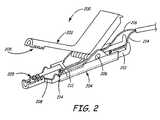
- FIG. 2illustrates a diagrammatic view of a Kelvin clamp in accordance with an embodiment of the present invention.
- FIGS. 3-1 to 3 - 3illustrate a method of forming a Kelvin clamp in accordance with an embodiment of the present invention.
- FIGS. 4-1 to 4 - 3illustrate a method of forming a Kelvin clamp in accordance with an embodiment of the present invention.
- FIG. 5is a simplified block diagram of a battery tester with which the present invention is useful.
- FIG. 6is a simplified block diagram of a battery charger with which the present invention is useful.
- FIGS. 1-1 to 1 - 3illustrate examples of different battery contacts that the Kelvin clamp of the present invention is capable of grasping.
- battery contactrefers to either terminal 102 or terminal 104 of battery 100 .
- FIG. 1-2shows battery 105 connected with clamps that connect to an external circuit (not shown).
- battery contactrefers to a battery terminal with an attached clamp.
- terminal 110 with attached clamp 114 or terminal 112 with attached clamp 116qualifies as a battery contact to which the Kelvin clamp of the present invention can be applied.
- FIG. 1-1battery contact refers to either terminal 102 or terminal 104 of battery 100 .
- FIG. 1-2shows battery 105 connected with clamps that connect to an external circuit (not shown).
- battery contactrefers to a battery terminal with an attached clamp.
- terminal 110 with attached clamp 114 or terminal 112 with attached clamp 116qualifies as a battery contact to which the Kelvin clamp of the present invention can be applied.
- FIGS. 1-1 to 1 - 3shows battery 120 with clamps that grip bolts (terminals) connected to sides of battery 120 and connect to an external circuit (not shown) .
- bolt 124 with attached clamp 128 or bolt 126 with attached clamp 130qualifies as a battery contact.
- the term battery contactis not restricted in application to the illustrative examples of FIGS. 1-1 to 1 - 3 .
- FIG. 2shows a Kelvin clamp 200 in accordance with an embodiment of the present invention.
- Kelvin clamp 200is designed to electrically couple electrical conductors, such as 214 and 216 , of a Kelvin connection, to a battery contact (not shown in FIG. 2 ).
- Kelvin clamp 200includes a first electrically conductive arm 202 and a second arm 204 that are pivotally connected together. Arms 202 and 204 each include grasping portions 205 , which are capable of grasping a battery contact. Second arm 204 includes a first electrically conductive piece 208 and a second electrically conductive piece 210 . Electrically conductive pieces 208 and 210 are mechanically coupled together and electrically isolated from each other by insulator 212 . First arm 202 is connected to second piece 210 of second arm 204 by pivot 206 , such that first arm 202 and second piece 210 of second arm 204 are both electrically and mechanically coupled together to form a first electrically conductive portion of Kelvin clamp 200 .
- Conductive piece 208forms a second electrically conductive portion of Kelvin clamp 200 .
- First electrical conductor 214 of a Kelvin connectionis electrically coupled to the first electrically conductive portion formed by arm 202 and conductive piece 210 and second electrical conductor 216 of the Kelvin connection is electrically coupled to conductive piece 208 of second arm 204 .
- electrical conductors 214 and 216are soldered to the respective electrically conductive portions of clamp 200 .
- electrical conductor 214is one of a pair of Kelvin connectors that measures voltage across the battery contacts
- electrical conductor 216is one of a pair of Kelvin connectors that injects current into the battery through the battery contacts.
- Conductor 216which is connected to conductive piece 208 , is preferably employed to inject current since conductive piece 208 is relatively small, and therefore, does not substantially add to the resistance of the current path. In this configuration, greater accuracy in measurements can be obtained.
- electrically conductive arm 202 and electrically conductive pieces 208 and 210may be formed of an electrically conductive material such as copper.
- insulating grips(not shown) are provided on each arm ( 202 , 204 ) for user protection.
- FIG. 2shows one example embodiment of a Kelvin clamp 200 in accordance with the present invention.
- any Kelvin clampwith a first electrically conductive arm and a second arm separated into first and second electrically conductive pieces which are mechanically coupled together and electrically isolated from each other, is within the scope of the present invention.
- FIGS. 3-1 to 3 - 3collectively illustrate a method of forming a Kelvin clamp in accordance with an embodiment of the present invention.
- the methodincludes providing a first electrically conductive arm 202 and first and second electrically conductive pieces 208 and 210 , which are illustrated in FIG. 3-1.
- Conductive pieces 208 and 210may be formed by separating a single conductive piece of an arm of a clip.
- Arm 202 and conductive piece 210include groove 300 , which are substantially similar in size.
- Arm 202 and conductive piece 208include substantially similar grasping portions 205 .
- First and second electrically conductive pieces 208 and 210are coupled together by insulator 212 to form a second arm 204 as shown in FIG. 3-2.
- insulator 212may be formed around pieces 208 and 210 . In other embodiments, insulator 212 may be molded into a suitable shape, and conductive pieces 208 and 210 may be attached to insulator 212 with rivets or screws, such as 213 .
- First arm 202 and second arm 204are then pivotally connected together through grooves 300 with the help of a spring mechanism 302 that can include a leaf spring and a bolt extending through grooves 300 to form Kelvin clamp 200 of the present invention as shown in FIG. 3-3. The leaf spring urges grasping portions 205 of arms 202 and 204 together.
- Kelvin electrical conductorssuch as 214 and 216 (shown in FIG. 2) are soldered to conductive pieces 208 and 210 .
- FIGS. 4-1 to 4 - 3collectively illustrate a method of forming a Kelvin clamp in accordance with another embodiment of the present invention.
- This method embodimentincludes providing a clip, shown in FIG. 4-1, having a first electrically conductive arm 202 and a second electrically conductive arm 204 . Arms 202 and 204 are pivotally connected together and include grasping portions 205 . Second conductive arm 204 is separated into a first electrically conductive piece 208 and a second electrically conductive piece 210 using any suitable tool capable of cutting metal. The clip with separated arm 204 is shown in FIG. 4-2. First and second electrically conductive pieces 208 and 210 are then coupled together by insulator 212 to form Kelvin clamp 200 of the present invention (FIG. 4 - 3 ). Coupling of pieces 208 and 210 with insulation 212 is carried out as described above in connection with FIG. 3-2.
- Embodiments of the present inventionare particularly useful with equipment for testing and charging storage batteries.
- Battery testers and chargers employing Kelvin clamps in accordance with the present inventionare described below in connection with FIGS. 5 and 6.
- FIG. 5is a simplified block diagram of electronic battery tester circuitry 500 with which the present invention is useful.
- a four point (or Kelvin connection) techniqueis used to couple system 500 to battery 502 .
- Kelvin connections 508 and 510are used to couple, to battery contacts 504 and 506 , respectively, of battery 502 .
- Kelvin connection 508includes two individual connections 508 A and 508 B.
- Kelvin connection 510includes two individual connections, 510 A and 510 B.
- Kelvin clamps 200 of the present inventiongrasp battery contacts 504 and 506 and couple them to electrical connections 508 , 510 .
- Circuitry 500includes a current source 512 and a differential amplifier 514 .
- Current source 512is coupled to connections 508 B and 510 B of Kelvin connections 508 and 510 , respectively.
- Differential amplifier 514is coupled to connection 508 A and connection 510 A of Kelvin connections 508 and 510 , respectively.
- An output from differential amplifier 514is provided to analog to digital converter 518 which itself provides a digitized output to microprocessor 520 .
- Microprocessor 520is connected to a system clock 522 , a memory 524 , and analog to digital converter 518 .
- Microprocessor 520is also capable of receiving an input from an input device 526 and providing an output of output device 528 .
- the inputcan be, for example, a rating for the battery 502 .
- Input device 526can comprise any or multiple types of input devices.
- the result of a battery testcan be an output device 528 .
- Device 528can be a display or other output.
- the inventioncan operate with any technique for determining a voltage across battery 502 and a current through battery 502 and is not limited to the specific techniques set forth herein.
- the forcing function source or current source 512can provide any signal having a time varying component, including a stepped pulse or a periodic signal, having any shape, applied to battery 502 .
- the current sourcecan be an active source in which the current source signal is injected into battery 502 , or can be a passive source, such as a load, which is switched on under the control of microprocessor 520 .
- microprocessor 520can receive an input through input 526 , such as a rating for battery 502 .
- Microprocessor 520determines a dynamic parameter, such as dynamic conductance, of battery 502 as a function of sensed voltage and current. The change in these sensed values is used to determine the dynamic parameter.
- the dynamic conductance ( ⁇ G)is determined as:
- a temperature sensor 530can be thermally coupled to battery 502 and used to compensate battery measurements. Temperature readings can be stored in memory 524 for later retrieval.
- FIG. 6is a simplified block diagram of a battery charging system 600 using the present invention.
- System 600is shown coupled to battery 602 .
- System 600includes battery charging and testing circuitry 604 and microprocessor 606 .
- System 600couples to battery contacts 608 and 610 through Kelvin electrical connections 612 and 614 respectively.
- Electrical connection 612includes a first connection 612 A and second connection 612 B and connection 614 includes a first connection 614 A and a second connection 614 B.
- Kelvin clamps 200 of the present inventionprovide coupling between battery contacts 608 and 610 and electrical connections 612 and 614 .
- Battery charger 600operates in a manner similar to the battery charger set forth in U.S. Pat. No. 6,104,167, issued Aug. 15, 2000, and entitled “METHOD AND APPARATUS FOR CHARGING A BATTERY”, which is incorporated herein by reference.
Landscapes
- Charge And Discharge Circuits For Batteries Or The Like (AREA)
- Secondary Cells (AREA)
- Measuring Leads Or Probes (AREA)
Abstract
Description
The present invention generally relates to storage batteries. More specifically, the present invention relates to a Kelvin clamp for electrically coupling to storage batteries.
Storage batteries, such as lead acid storage batteries of the type used in the automotive industry, have existed for many years. However, understanding the nature of such storage batteries, how such storage batteries operate and how to accurately test such batteries has been an ongoing endeavor and has proved quite difficult. Storage batteries consist of a plurality of individual storage cells electrically connected in series. Typically, each cell has a voltage potential of about 2.1 volts. By connecting the cells in series, the voltage of the individual cells are added in a cumulative manner. For example, in a typical automotive storage battery, six storage cells are used to provide a total voltage when the battery is fully charged up to 12.6 volts.
Several techniques have been used to test the condition of storage batteries. These techniques include a voltage test to determine if the battery voltage is below a certain threshold, and a load test that involves discharging a battery using a known load. A more recent technique involves measuring the conductance of the storage batteries. This technique typically involves the use of Kelvin connections for testing equipment. A Kelvin connection is a four point connection technique that allows current to be injected into a battery through a first pair of connectors attached to the battery contacts, while a second pair of connectors is attached to the battery contacts in order to measure the voltage across the posts. Various types of clamps have been designed to couple to the battery terminals and to continue the circuit that includes the Kelvin connection. However, these prior art clamps are complex and costly.
A Kelvin clamp for coupling a first electrical conductor and a second electrical conductor to a battery contact to provide a Kelvin connection to the battery contact is provided. The Kelvin clamp includes a first electrically conductive arm having a first grasping portion that can couple to the battery contact and to the first electrical conductor. Also included is a second arm that has a first electrically conductive piece and a second electrically conductive piece, which are mechanically coupled together and electrically isolated from each other. The first electrically conductive piece has a second grasping portion that can couple to the battery contact. The first electrically conductive piece can also couple to the second electrical conductor. The first electrically conductive arm and the second electrically conductive piece are electrically and mechanically coupled together by a spring mechanism.
FIGS. 1-1 to1-3 illustrate cross-sections of prior art battery contacts that the Kelvin clamp of the present invention is capable of grasping.
FIG. 2 illustrates a diagrammatic view of a Kelvin clamp in accordance with an embodiment of the present invention.
FIGS. 3-1 to3-3 illustrate a method of forming a Kelvin clamp in accordance with an embodiment of the present invention.
FIGS. 4-1 to4-3 illustrate a method of forming a Kelvin clamp in accordance with an embodiment of the present invention.
FIG. 5 is a simplified block diagram of a battery tester with which the present invention is useful.
FIG. 6 is a simplified block diagram of a battery charger with which the present invention is useful.
In the discussion below, the term “battery contact” is used to define a portion of the battery onto which the Kelvin clamp of the present invention can be applied. Prior art FIGS. 1-1 to1-3 illustrate examples of different battery contacts that the Kelvin clamp of the present invention is capable of grasping. In FIG. 1-1, battery contact refers to eitherterminal 102 orterminal 104 ofbattery 100. FIG. 1-2 showsbattery 105 connected with clamps that connect to an external circuit (not shown). Here the term battery contact refers to a battery terminal with an attached clamp. Thus, eitherterminal 110 with attachedclamp 114 orterminal 112 with attachedclamp 116 qualifies as a battery contact to which the Kelvin clamp of the present invention can be applied. Similarly, FIG. 1-3 showsbattery 120 with clamps that grip bolts (terminals) connected to sides ofbattery 120 and connect to an external circuit (not shown) . Here eitherbolt 124 with attachedclamp 128 orbolt 126 with attachedclamp 130 qualifies as a battery contact. The term battery contact is not restricted in application to the illustrative examples of FIGS. 1-1 to1-3.
FIG. 2 shows a Kelvinclamp 200 in accordance with an embodiment of the present invention. The same reference numerals are used in the various figures to represent the same or similar elements. Kelvinclamp 200 is designed to electrically couple electrical conductors, such as214 and216, of a Kelvin connection, to a battery contact (not shown in FIG.2).
As can be seen in FIG. 2, Kelvinclamp 200 includes a first electricallyconductive arm 202 and asecond arm 204 that are pivotally connected together.Arms portions 205, which are capable of grasping a battery contact.Second arm 204 includes a first electricallyconductive piece 208 and a second electricallyconductive piece 210. Electricallyconductive pieces insulator 212.First arm 202 is connected tosecond piece 210 ofsecond arm 204 bypivot 206, such thatfirst arm 202 andsecond piece 210 ofsecond arm 204 are both electrically and mechanically coupled together to form a first electrically conductive portion of Kelvinclamp 200.Conductive piece 208 forms a second electrically conductive portion of Kelvinclamp 200. Firstelectrical conductor 214 of a Kelvin connection is electrically coupled to the first electrically conductive portion formed byarm 202 andconductive piece 210 and secondelectrical conductor 216 of the Kelvin connection is electrically coupled toconductive piece 208 ofsecond arm 204. In embodiments of the present invention,electrical conductors clamp 200. In some embodiments of the present invention,electrical conductor 214 is one of a pair of Kelvin connectors that measures voltage across the battery contacts, andelectrical conductor 216 is one of a pair of Kelvin connectors that injects current into the battery through the battery contacts.Conductor 216, which is connected toconductive piece 208, is preferably employed to inject current sinceconductive piece 208 is relatively small, and therefore, does not substantially add to the resistance of the current path. In this configuration, greater accuracy in measurements can be obtained.
In general, electricallyconductive arm 202 and electricallyconductive pieces clamp 200 in accordance with the present invention. However, any Kelvin clamp with a first electrically conductive arm and a second arm separated into first and second electrically conductive pieces which are mechanically coupled together and electrically isolated from each other, is within the scope of the present invention.
FIGS. 3-1 to3-3 collectively illustrate a method of forming a Kelvin clamp in accordance with an embodiment of the present invention. The method includes providing a first electricallyconductive arm 202 and first and second electricallyconductive pieces Conductive pieces Arm 202 andconductive piece 210 includegroove 300, which are substantially similar in size.Arm 202 andconductive piece 208 include substantially similar graspingportions 205. First and second electricallyconductive pieces insulator 212 to form asecond arm 204 as shown in FIG. 3-2. In some embodiments,insulator 212 may be formed aroundpieces insulator 212 may be molded into a suitable shape, andconductive pieces insulator 212 with rivets or screws, such as213.First arm 202 andsecond arm 204 are then pivotally connected together throughgrooves 300 with the help of a spring mechanism302 that can include a leaf spring and a bolt extending throughgrooves 300 to form Kelvin clamp200 of the present invention as shown in FIG. 3-3. The leaf spring urges graspingportions 205 ofarms conductive pieces
FIGS. 4-1 to4-3 collectively illustrate a method of forming a Kelvin clamp in accordance with another embodiment of the present invention. This method embodiment includes providing a clip, shown in FIG. 4-1, having a first electricallyconductive arm 202 and a second electricallyconductive arm 204.Arms portions 205. Secondconductive arm 204 is separated into a first electricallyconductive piece 208 and a second electricallyconductive piece 210 using any suitable tool capable of cutting metal. The clip with separatedarm 204 is shown in FIG. 4-2. First and second electricallyconductive pieces insulator 212 to form Kelvin clamp200 of the present invention (FIG.4-3). Coupling ofpieces insulation 212 is carried out as described above in connection with FIG. 3-2.
Embodiments of the present invention, described above, are particularly useful with equipment for testing and charging storage batteries. Battery testers and chargers employing Kelvin clamps in accordance with the present invention are described below in connection with FIGS. 5 and 6.
FIG. 5 is a simplified block diagram of electronicbattery tester circuitry 500 with which the present invention is useful. A four point (or Kelvin connection) technique is used to couplesystem 500 tobattery 502.Kelvin connections battery contacts battery 502.Kelvin connection 508 includes twoindividual connections Kelvin connection 510 includes two individual connections,510A and510B. Kelvin clamps200 of the present invention graspbattery contacts electrical connections
In operation,microprocessor 520 can receive an input throughinput 526, such as a rating forbattery 502.Microprocessor 520 determines a dynamic parameter, such as dynamic conductance, ofbattery 502 as a function of sensed voltage and current. The change in these sensed values is used to determine the dynamic parameter. For example, the dynamic conductance (ΔG) is determined as:
where ΔI is the change in current flowing throughbattery 502 due tocurrent source 512 and ΔV is the change in battery voltage due to applied current ΔI. Atemperature sensor 530 can be thermally coupled tobattery 502 and used to compensate battery measurements. Temperature readings can be stored inmemory 524 for later retrieval.
FIG. 6 is a simplified block diagram of abattery charging system 600 using the present invention.System 600 is shown coupled tobattery 602.System 600 includes battery charging andtesting circuitry 604 andmicroprocessor 606.System 600 couples tobattery contacts electrical connections Electrical connection 612 includes afirst connection 612A andsecond connection 612B andconnection 614 includes afirst connection 614A and asecond connection 614B. Kelvin clamps200 of the present invention provide coupling betweenbattery contacts electrical connections Battery charger 600 operates in a manner similar to the battery charger set forth in U.S. Pat. No. 6,104,167, issued Aug. 15, 2000, and entitled “METHOD AND APPARATUS FOR CHARGING A BATTERY”, which is incorporated herein by reference.
Although the present invention has been described with reference to preferred embodiments, workers skilled in the art will recognize that changes may be made in form and detail without departing from the spirit and scope of the invention. Although the Kelvin clamp of the present invention has been described for use with storage batteries and for coupling battery charging and testing equipment to storage batteries, the invention can be employed in any system where Kelvin electrical connections and Kelvin clamps are utilized.
Claims (23)
1. A Kelvin clamp for coupling a first electrical conductor and a second electrical conductor to a battery contact of a storage battery to thereby provide a Kelvin connection to the battery contact through the first and second electrical conductors, the Kelvin clamp comprising:
a first electrically conductive arm having a first grasping portion configured to couple to the battery contact, the first electrically conductive arm further configured to couple to the first electrical conductor;
a second arm including a first electrically conductive piece and a second electrically conductive piece with the first electrically conductive piece and the second electrically conductive piece mechanically coupled together and electrically isolated from each other, the first electrically conductive piece of the second arm having a second grasping portion configured to couple to the battery contact and generally aligned with the first grasping portion, the first electrically conductive piece of the second arm further configured to couple to the second electrical conductor; and
wherein the first electrically conductive arm and the second electrically conductive piece of the second arm are electrically and mechanically coupled together by a spring mechanism, such that the first grasping portion and the second grasping portion are urged together.
2. The Kelvin clamp ofclaim 1 wherein the first electrically conductive arm and the second electrically conductive piece of the second arm are pivotally connected together.
3. The Kelvin claim ofclaim 1 wherein the first electrically conductive piece and the second electrically conductive piece are coupled to the insulator with rivets.
4. The Kelvin clamp ofclaim 1 wherein the first electrically conductive arm and the first and second electrically conductive pieces of the second arm comprise copper.
5. The Kelvin clamp ofclaim 1 wherein the insulator comprises plastic.
6. The Kelvin clamp ofclaim 1 wherein the insulator comprises a composite material.
7. A battery tester including the Kelvin clamp ofclaim 1 .
8. A battery charger including the Kelvin clamp ofclaim 1 .
9. The Kelvin clamp ofclaim 7 or8 wherein the first electrical conductor of the Kelvin connection is one of a first pair of Kelvin connectors that measures voltage across battery contacts, and wherein the second electrical conductor of the Kelvin connection is one of a second pair of Kelvin connectors that injects a forcing function into a battery through the battery contacts.
10. A method of forming a Kelvin clamp comprising:
providing a first electrically conductive arm;
connecting a first electrical conductor to the first electrically conductive arm;
providing a first electrically conductive piece having a terminal grasping portion and a coupling portion;
providing a second electrically conductive piece;
linking the coupling portion of the first electrically conductive piece and the second electrically conductive piece mechanically to form a second arm, with the first electrically conductive piece and the second electrically conductive piece electrically isolated from each other;
connecting a second electrical conductor to the first electrically conductive piece;
coupling the first arm and the second electrically conductive piece mechanically and electrically.
11. The method ofclaim 10 wherein the first electrically conductive arm and the first and second electrically conductive pieces of the second arm comprise copper.
12. A Kelvin clamp formed through the process ofclaim 10 .
13. The method ofclaim 10 wherein linking the coupling portion of the first electrically conductive piece and the second electrically conductive piece mechanically is carried out with an insulator.
14. The method ofclaim 13 wherein the insulator comprises plastic.
15. The method ofclaim 13 wherein the insulator comprises a composite material.
16. A method of forming a Kelvin clamp comprising:
providing a clip having a first electrically conductive arm and a second electrically conductive arm, with the first arm and the second arm electrically and mechanically coupled to each other;
connecting a first electrical conductor to the first electrically conductive arm;
separating the second arm into a first electrically conductive piece and a second electrically conductive piece, with the separation being carried out proximate a terminal grasping portion of the second arm, such that the terminal grasping portion is a part of the first electrically conductive piece, and such that the second electrically conductive piece remains electrically and mechanically coupled to the first arm after being separated from the first electrically conductive piece;
connecting a second electrical conductor to the first electrically conductive piece;
mechanically linking the first electrically conductive piece and the second electrically conductive piece such that the first electrically conductive piece is electrically isolated from the second electrically conductive piece.
17. The method ofclaim 16 wherein the first electrically conductive arm and the second electrically conductive arm comprise copper.
18. The method ofclaim 16 wherein mechanically linking the first electrically conductive piece and the second electrically conductive piece is carried out with an insulator.
19. The method ofclaim 18 wherein the insulator comprises plastic.
20. The method ofclaim 18 wherein the insulator comprises a composite material.
21. A Kelvin clamp formed through the process ofclaim 16 .
22. A battery tester including the Kelvin clamp ofclaim 21 .
23. A battery charger including the Kelvin clamp ofclaim 21 .
Priority Applications (1)
| Application Number | Priority Date | Filing Date | Title |
|---|---|---|---|
| US10/207,495US6623314B1 (en) | 2002-07-29 | 2002-07-29 | Kelvin clamp for electrically coupling to a battery contact |
Applications Claiming Priority (1)
| Application Number | Priority Date | Filing Date | Title |
|---|---|---|---|
| US10/207,495US6623314B1 (en) | 2002-07-29 | 2002-07-29 | Kelvin clamp for electrically coupling to a battery contact |
Publications (1)
| Publication Number | Publication Date |
|---|---|
| US6623314B1true US6623314B1 (en) | 2003-09-23 |
Family
ID=28041356
Family Applications (1)
| Application Number | Title | Priority Date | Filing Date |
|---|---|---|---|
| US10/207,495Expired - LifetimeUS6623314B1 (en) | 2002-07-29 | 2002-07-29 | Kelvin clamp for electrically coupling to a battery contact |
Country Status (1)
| Country | Link |
|---|---|
| US (1) | US6623314B1 (en) |
Cited By (99)
| Publication number | Priority date | Publication date | Assignee | Title |
|---|---|---|---|---|
| US20030157845A1 (en)* | 2001-02-02 | 2003-08-21 | Karl-Martin Kutteruf | Terminal connector |
| US20050124229A1 (en)* | 2003-12-09 | 2005-06-09 | Agnew James H. | Heavy duty, high efficiency jumper cables |
| GB2416596A (en)* | 2004-07-22 | 2006-02-01 | Midtronics Inc | Broad-band low-inductance cables for making Kelvin connections to electrochemical cells and batteries |
| US7003411B2 (en) | 1997-11-03 | 2006-02-21 | Midtronics, Inc. | Electronic battery tester with network communication |
| US7034541B2 (en) | 2001-10-17 | 2006-04-25 | Midtronics, Inc. | Query based electronic battery tester |
| US20060263683A1 (en)* | 2005-05-09 | 2006-11-23 | Junill Yoon | Three-dimensional electrode terminal for pouch-typed battery |
| US7154276B2 (en) | 2003-09-05 | 2006-12-26 | Midtronics, Inc. | Method and apparatus for measuring a parameter of a vehicle electrical system |
| US7398176B2 (en) | 2000-03-27 | 2008-07-08 | Midtronics, Inc. | Battery testers with secondary functionality |
| DE112006002329T5 (en) | 2005-08-29 | 2008-07-10 | Midtronics, Inc., Willowbrook | Diagnostic device for electrical installations of motor vehicles |
| US7408358B2 (en) | 2003-06-16 | 2008-08-05 | Midtronics, Inc. | Electronic battery tester having a user interface to configure a printer |
| US7446536B2 (en) | 2000-03-27 | 2008-11-04 | Midtronics, Inc. | Scan tool for electronic battery tester |
| US7498767B2 (en) | 2005-02-16 | 2009-03-03 | Midtronics, Inc. | Centralized data storage of condition of a storage battery at its point of sale |
| US7505856B2 (en) | 1999-04-08 | 2009-03-17 | Midtronics, Inc. | Battery test module |
| US7545146B2 (en) | 2004-12-09 | 2009-06-09 | Midtronics, Inc. | Apparatus and method for predicting battery capacity and fitness for service from a battery dynamic parameter and a recovery voltage differential |
| US7557586B1 (en) | 1999-11-01 | 2009-07-07 | Midtronics, Inc. | Electronic battery tester |
| US7595643B2 (en) | 2003-11-11 | 2009-09-29 | Midtronics, Inc. | Apparatus and method for simulating a battery tester with a fixed resistance load |
| US7598699B2 (en) | 2004-02-20 | 2009-10-06 | Midtronics, Inc. | Replaceable clamp for electronic battery tester |
| US7598744B2 (en) | 2000-03-27 | 2009-10-06 | Midtronics, Inc. | Scan tool for electronic battery tester |
| US7598743B2 (en) | 2000-03-27 | 2009-10-06 | Midtronics, Inc. | Battery maintenance device having databus connection |
| US7619417B2 (en) | 2002-12-31 | 2009-11-17 | Midtronics, Inc. | Battery monitoring system |
| US7642787B2 (en) | 1997-11-03 | 2010-01-05 | Midtronics Inc. | Automotive vehicle electrical system diagnostic device |
| US7642786B2 (en) | 2004-06-01 | 2010-01-05 | Midtronics, Inc. | Battery tester capable of identifying faulty battery post adapters |
| US7688074B2 (en) | 1997-11-03 | 2010-03-30 | Midtronics, Inc. | Energy management system for automotive vehicle |
| US20100088050A1 (en)* | 2008-10-07 | 2010-04-08 | Keuss Steven D | Portable heavy load battery testing system and method |
| US7706991B2 (en) | 1996-07-29 | 2010-04-27 | Midtronics, Inc. | Alternator tester |
| US7705602B2 (en) | 1997-11-03 | 2010-04-27 | Midtronics, Inc. | Automotive vehicle electrical system diagnostic device |
| US7710119B2 (en) | 2004-12-09 | 2010-05-04 | Midtronics, Inc. | Battery tester that calculates its own reference values |
| DE102009051235A1 (en) | 2008-10-30 | 2010-05-06 | Midtronics, Inc., Willowbrook | Vehicle electrical system tester for testing electrical system of vehicle has test connection that thaws current from battery along path through wire and returns current to battery, to measure electrical parameter of wire with sensor |
| US20100136854A1 (en)* | 2008-03-27 | 2010-06-03 | Auto Meter Products, Inc. | Battery clamp for use with top post and side post batteries and methods for using the same |
| US7772850B2 (en) | 2004-07-12 | 2010-08-10 | Midtronics, Inc. | Wireless battery tester with information encryption means |
| US7774151B2 (en) | 1997-11-03 | 2010-08-10 | Midtronics, Inc. | Wireless battery monitor |
| US7777612B2 (en) | 2004-04-13 | 2010-08-17 | Midtronics, Inc. | Theft prevention device for automotive vehicle service centers |
| US7791348B2 (en) | 2007-02-27 | 2010-09-07 | Midtronics, Inc. | Battery tester with promotion feature to promote use of the battery tester by providing the user with codes having redeemable value |
| US7808375B2 (en) | 2007-04-16 | 2010-10-05 | Midtronics, Inc. | Battery run down indicator |
| US7959476B2 (en)* | 2008-06-16 | 2011-06-14 | Midtronics, Inc. | Clamp for electrically coupling to a battery contact |
| US7977914B2 (en) | 2003-10-08 | 2011-07-12 | Midtronics, Inc. | Battery maintenance tool with probe light |
| US7999505B2 (en) | 1997-11-03 | 2011-08-16 | Midtronics, Inc. | In-vehicle battery monitor |
| WO2011159455A1 (en) | 2010-06-18 | 2011-12-22 | Midtronics, Inc. | Battery maintenance device with thermal buffer |
| US8198900B2 (en) | 1996-07-29 | 2012-06-12 | Midtronics, Inc. | Automotive battery charging system tester |
| US8203345B2 (en) | 2007-12-06 | 2012-06-19 | Midtronics, Inc. | Storage battery and battery tester |
| US8306690B2 (en) | 2007-07-17 | 2012-11-06 | Midtronics, Inc. | Battery tester for electric vehicle |
| US8344685B2 (en) | 2004-08-20 | 2013-01-01 | Midtronics, Inc. | System for automatically gathering battery information |
| US8436619B2 (en) | 2004-08-20 | 2013-05-07 | Midtronics, Inc. | Integrated tag reader and environment sensor |
| US8442877B2 (en) | 2004-08-20 | 2013-05-14 | Midtronics, Inc. | Simplification of inventory management |
| US8513949B2 (en) | 2000-03-27 | 2013-08-20 | Midtronics, Inc. | Electronic battery tester or charger with databus connection |
| CN103296490A (en)* | 2013-06-22 | 2013-09-11 | 青岛歌尔声学科技有限公司 | Novel wire clamp for test |
| US8738309B2 (en) | 2010-09-30 | 2014-05-27 | Midtronics, Inc. | Battery pack maintenance for electric vehicles |
| US8872517B2 (en) | 1996-07-29 | 2014-10-28 | Midtronics, Inc. | Electronic battery tester with battery age input |
| US8958998B2 (en) | 1997-11-03 | 2015-02-17 | Midtronics, Inc. | Electronic battery tester with network communication |
| US20150064990A1 (en)* | 2013-09-03 | 2015-03-05 | Shou-Chun Tsai | Alligator clip |
| US9018958B2 (en) | 2003-09-05 | 2015-04-28 | Midtronics, Inc. | Method and apparatus for measuring a parameter of a vehicle electrical system |
| WO2015089249A1 (en) | 2013-12-12 | 2015-06-18 | Midtronics, Inc. | Battery tester and battery registration tool |
| EP2897229A1 (en) | 2014-01-16 | 2015-07-22 | Midtronics, Inc. | Battery clamp with endoskeleton design |
| US9201120B2 (en) | 2010-08-12 | 2015-12-01 | Midtronics, Inc. | Electronic battery tester for testing storage battery |
| US9229062B2 (en) | 2010-05-27 | 2016-01-05 | Midtronics, Inc. | Electronic storage battery diagnostic system |
| US9244100B2 (en) | 2013-03-15 | 2016-01-26 | Midtronics, Inc. | Current clamp with jaw closure detection |
| US9255955B2 (en) | 2003-09-05 | 2016-02-09 | Midtronics, Inc. | Method and apparatus for measuring a parameter of a vehicle electrical system |
| US20160051260A1 (en)* | 2013-04-02 | 2016-02-25 | Xavier Renard | System for joining two blood vessels |
| US9274157B2 (en) | 2007-07-17 | 2016-03-01 | Midtronics, Inc. | Battery tester for electric vehicle |
| US9312575B2 (en) | 2013-05-16 | 2016-04-12 | Midtronics, Inc. | Battery testing system and method |
| WO2016123075A1 (en) | 2015-01-26 | 2016-08-04 | Midtronics, Inc. | Alternator tester |
| US9425487B2 (en) | 2010-03-03 | 2016-08-23 | Midtronics, Inc. | Monitor for front terminal batteries |
| WO2016176405A1 (en) | 2015-04-29 | 2016-11-03 | Midtronics, Inc. | Calibration and programming of in-vehicle battery sensors |
| US9496720B2 (en) | 2004-08-20 | 2016-11-15 | Midtronics, Inc. | System for automatically gathering battery information |
| US9537332B2 (en) | 2013-05-30 | 2017-01-03 | Canara, Inc. | Apparatus, system and method for charge balancing of individual batteries in a string of batteries using battery voltage and temperature, and detecting and preventing thermal runaway |
| US9588185B2 (en) | 2010-02-25 | 2017-03-07 | Keith S. Champlin | Method and apparatus for detecting cell deterioration in an electrochemical cell or battery |
| US9755331B2 (en)* | 2015-01-07 | 2017-09-05 | William Ernest Swan | Electrical wire connector |
| US9851411B2 (en) | 2012-06-28 | 2017-12-26 | Keith S. Champlin | Suppressing HF cable oscillations during dynamic measurements of cells and batteries |
| US9966676B2 (en) | 2015-09-28 | 2018-05-08 | Midtronics, Inc. | Kelvin connector adapter for storage battery |
| US10046649B2 (en) | 2012-06-28 | 2018-08-14 | Midtronics, Inc. | Hybrid and electric vehicle battery pack maintenance device |
| US10120034B2 (en) | 2015-10-07 | 2018-11-06 | Canara, Inc. | Battery string monitoring system |
| US10222397B2 (en) | 2014-09-26 | 2019-03-05 | Midtronics, Inc. | Cable connector for electronic battery tester |
| WO2019147546A1 (en) | 2018-01-23 | 2019-08-01 | Midtronics, Inc. | High capacity battery balancer |
| WO2019147549A1 (en) | 2018-01-23 | 2019-08-01 | Midtronics, Inc. | Hybrid and electric vehicle battery maintenance device |
| US20190282114A1 (en)* | 2017-10-25 | 2019-09-19 | Shenzhen Launch Electrical Co., Ltd | Multi-functional adapter clip |
| US10429449B2 (en) | 2011-11-10 | 2019-10-01 | Midtronics, Inc. | Battery pack tester |
| US10473555B2 (en) | 2014-07-14 | 2019-11-12 | Midtronics, Inc. | Automotive maintenance system |
| US10608353B2 (en) | 2016-06-28 | 2020-03-31 | Midtronics, Inc. | Battery clamp |
| US10843574B2 (en) | 2013-12-12 | 2020-11-24 | Midtronics, Inc. | Calibration and programming of in-vehicle battery sensors |
| WO2021092109A1 (en) | 2019-11-05 | 2021-05-14 | Midtronics, Inc. | System for charging a series of connected batteries |
| CN112864643A (en)* | 2021-01-08 | 2021-05-28 | 天能电池集团(安徽)有限公司 | Storage battery charging clamp device |
| US11054480B2 (en) | 2016-10-25 | 2021-07-06 | Midtronics, Inc. | Electrical load for electronic battery tester and electronic battery tester including such electrical load |
| US11325479B2 (en) | 2012-06-28 | 2022-05-10 | Midtronics, Inc. | Hybrid and electric vehicle battery maintenance device |
| CN114545210A (en)* | 2022-04-21 | 2022-05-27 | 立臻精密智造(昆山)有限公司 | Circuit testing device |
| US11474153B2 (en) | 2019-11-12 | 2022-10-18 | Midtronics, Inc. | Battery pack maintenance system |
| US11486930B2 (en) | 2020-01-23 | 2022-11-01 | Midtronics, Inc. | Electronic battery tester with battery clamp storage holsters |
| US11513160B2 (en) | 2018-11-29 | 2022-11-29 | Midtronics, Inc. | Vehicle battery maintenance device |
| US11566972B2 (en) | 2019-07-31 | 2023-01-31 | Midtronics, Inc. | Tire tread gauge using visual indicator |
| US11650259B2 (en) | 2010-06-03 | 2023-05-16 | Midtronics, Inc. | Battery pack maintenance for electric vehicle |
| US11668779B2 (en) | 2019-11-11 | 2023-06-06 | Midtronics, Inc. | Hybrid and electric vehicle battery pack maintenance device |
| US11740294B2 (en) | 2010-06-03 | 2023-08-29 | Midtronics, Inc. | High use battery pack maintenance |
| US11973202B2 (en) | 2019-12-31 | 2024-04-30 | Midtronics, Inc. | Intelligent module interface for battery maintenance device |
| WO2024258934A1 (en) | 2023-06-13 | 2024-12-19 | Midtronics, Inc. | Electric vehicle maintenance device for low voltage electrical system |
| US12237482B2 (en) | 2019-12-31 | 2025-02-25 | Midtronics, Inc. | Intelligent module interface for battery maintenance device |
| WO2025085631A1 (en) | 2023-10-18 | 2025-04-24 | Midtronics, Inc. | Electric vehicle maintenance device abstract of the disclosure |
| WO2025096499A1 (en) | 2023-10-30 | 2025-05-08 | Midtronics, Inc. | Vehicle maintenance system with dynamic network |
| US12320857B2 (en) | 2016-10-25 | 2025-06-03 | Midtronics, Inc. | Electrical load for electronic battery tester and electronic battery tester including such electrical load |
| US12330513B2 (en) | 2022-02-14 | 2025-06-17 | Midtronics, Inc. | Battery maintenance device with high voltage connector |
| US12392833B2 (en) | 2022-05-09 | 2025-08-19 | Midtronics, Inc. | Electronic battery tester |
Citations (6)
| Publication number | Priority date | Publication date | Assignee | Title |
|---|---|---|---|---|
| US2000665A (en)* | 1930-02-10 | 1935-05-07 | Joseph Weidenhoff | Battery clip |
| US4620767A (en)* | 1985-02-21 | 1986-11-04 | East Penn Manufacturing Co., Inc. | Combination battery booster cable connector |
| US4934957A (en)* | 1989-08-15 | 1990-06-19 | Bellusci Albert V | Automotive battery terminal clamp for a battery jumper cable |
| US5772468A (en)* | 1996-09-27 | 1998-06-30 | Coleman Cable System, Inc. | Clamp assembly for a battery booster cable |
| US6140797A (en) | 1998-10-08 | 2000-10-31 | Dunn; James P. | Compact improved autonomous auxiliary engine starting apparatus |
| US6238253B1 (en)* | 2000-03-06 | 2001-05-29 | Phillip L. Qualls | Battery terminal gripping assembly |
- 2002
- 2002-07-29USUS10/207,495patent/US6623314B1/ennot_activeExpired - Lifetime
Patent Citations (6)
| Publication number | Priority date | Publication date | Assignee | Title |
|---|---|---|---|---|
| US2000665A (en)* | 1930-02-10 | 1935-05-07 | Joseph Weidenhoff | Battery clip |
| US4620767A (en)* | 1985-02-21 | 1986-11-04 | East Penn Manufacturing Co., Inc. | Combination battery booster cable connector |
| US4934957A (en)* | 1989-08-15 | 1990-06-19 | Bellusci Albert V | Automotive battery terminal clamp for a battery jumper cable |
| US5772468A (en)* | 1996-09-27 | 1998-06-30 | Coleman Cable System, Inc. | Clamp assembly for a battery booster cable |
| US6140797A (en) | 1998-10-08 | 2000-10-31 | Dunn; James P. | Compact improved autonomous auxiliary engine starting apparatus |
| US6238253B1 (en)* | 2000-03-06 | 2001-05-29 | Phillip L. Qualls | Battery terminal gripping assembly |
Non-Patent Citations (1)
| Title |
|---|
| "Alligator Clips with Wire Penetrators" J.S. Popper, Inc. product information, downloaded from http://www.jspopper.com/, undated. |
Cited By (140)
| Publication number | Priority date | Publication date | Assignee | Title |
|---|---|---|---|---|
| US7706991B2 (en) | 1996-07-29 | 2010-04-27 | Midtronics, Inc. | Alternator tester |
| US8198900B2 (en) | 1996-07-29 | 2012-06-12 | Midtronics, Inc. | Automotive battery charging system tester |
| US7656162B2 (en) | 1996-07-29 | 2010-02-02 | Midtronics Inc. | Electronic battery tester with vehicle type input |
| US7940052B2 (en) | 1996-07-29 | 2011-05-10 | Midtronics, Inc. | Electronic battery test based upon battery requirements |
| US8872517B2 (en) | 1996-07-29 | 2014-10-28 | Midtronics, Inc. | Electronic battery tester with battery age input |
| US7003411B2 (en) | 1997-11-03 | 2006-02-21 | Midtronics, Inc. | Electronic battery tester with network communication |
| US8493022B2 (en) | 1997-11-03 | 2013-07-23 | Midtronics, Inc. | Automotive vehicle electrical system diagnostic device |
| US7705602B2 (en) | 1997-11-03 | 2010-04-27 | Midtronics, Inc. | Automotive vehicle electrical system diagnostic device |
| US7642787B2 (en) | 1997-11-03 | 2010-01-05 | Midtronics Inc. | Automotive vehicle electrical system diagnostic device |
| US7999505B2 (en) | 1997-11-03 | 2011-08-16 | Midtronics, Inc. | In-vehicle battery monitor |
| US8674654B2 (en) | 1997-11-03 | 2014-03-18 | Midtronics, Inc. | In-vehicle battery monitor |
| US8958998B2 (en) | 1997-11-03 | 2015-02-17 | Midtronics, Inc. | Electronic battery tester with network communication |
| US7774151B2 (en) | 1997-11-03 | 2010-08-10 | Midtronics, Inc. | Wireless battery monitor |
| US7688074B2 (en) | 1997-11-03 | 2010-03-30 | Midtronics, Inc. | Energy management system for automotive vehicle |
| US7505856B2 (en) | 1999-04-08 | 2009-03-17 | Midtronics, Inc. | Battery test module |
| US8754653B2 (en) | 1999-11-01 | 2014-06-17 | Midtronics, Inc. | Electronic battery tester |
| US7557586B1 (en) | 1999-11-01 | 2009-07-07 | Midtronics, Inc. | Electronic battery tester |
| US7398176B2 (en) | 2000-03-27 | 2008-07-08 | Midtronics, Inc. | Battery testers with secondary functionality |
| US8513949B2 (en) | 2000-03-27 | 2013-08-20 | Midtronics, Inc. | Electronic battery tester or charger with databus connection |
| US8872516B2 (en) | 2000-03-27 | 2014-10-28 | Midtronics, Inc. | Electronic battery tester mounted in a vehicle |
| US7924015B2 (en) | 2000-03-27 | 2011-04-12 | Midtronics, Inc. | Automotive vehicle battery test system |
| US9052366B2 (en) | 2000-03-27 | 2015-06-09 | Midtronics, Inc. | Battery testers with secondary functionality |
| US7446536B2 (en) | 2000-03-27 | 2008-11-04 | Midtronics, Inc. | Scan tool for electronic battery tester |
| US8237448B2 (en) | 2000-03-27 | 2012-08-07 | Midtronics, Inc. | Battery testers with secondary functionality |
| US7728597B2 (en) | 2000-03-27 | 2010-06-01 | Midtronics, Inc. | Electronic battery tester with databus |
| US7598744B2 (en) | 2000-03-27 | 2009-10-06 | Midtronics, Inc. | Scan tool for electronic battery tester |
| US7598743B2 (en) | 2000-03-27 | 2009-10-06 | Midtronics, Inc. | Battery maintenance device having databus connection |
| US20030157845A1 (en)* | 2001-02-02 | 2003-08-21 | Karl-Martin Kutteruf | Terminal connector |
| US6910915B2 (en)* | 2001-02-02 | 2005-06-28 | Robert Bosch Gmbh | Terminal connector |
| US7363175B2 (en) | 2001-10-17 | 2008-04-22 | Midtronics, Inc. | Query based electronic battery tester |
| US7034541B2 (en) | 2001-10-17 | 2006-04-25 | Midtronics, Inc. | Query based electronic battery tester |
| US7619417B2 (en) | 2002-12-31 | 2009-11-17 | Midtronics, Inc. | Battery monitoring system |
| US7408358B2 (en) | 2003-06-16 | 2008-08-05 | Midtronics, Inc. | Electronic battery tester having a user interface to configure a printer |
| US8674711B2 (en) | 2003-09-05 | 2014-03-18 | Midtronics, Inc. | Method and apparatus for measuring a parameter of a vehicle electrical system |
| US9018958B2 (en) | 2003-09-05 | 2015-04-28 | Midtronics, Inc. | Method and apparatus for measuring a parameter of a vehicle electrical system |
| US8164343B2 (en) | 2003-09-05 | 2012-04-24 | Midtronics, Inc. | Method and apparatus for measuring a parameter of a vehicle electrical system |
| US7154276B2 (en) | 2003-09-05 | 2006-12-26 | Midtronics, Inc. | Method and apparatus for measuring a parameter of a vehicle electrical system |
| US9255955B2 (en) | 2003-09-05 | 2016-02-09 | Midtronics, Inc. | Method and apparatus for measuring a parameter of a vehicle electrical system |
| US7977914B2 (en) | 2003-10-08 | 2011-07-12 | Midtronics, Inc. | Battery maintenance tool with probe light |
| US7595643B2 (en) | 2003-11-11 | 2009-09-29 | Midtronics, Inc. | Apparatus and method for simulating a battery tester with a fixed resistance load |
| US20050124229A1 (en)* | 2003-12-09 | 2005-06-09 | Agnew James H. | Heavy duty, high efficiency jumper cables |
| US7008259B2 (en)* | 2003-12-09 | 2006-03-07 | Agnew James H | Heavy duty, high efficiency jumper cables |
| US7598699B2 (en) | 2004-02-20 | 2009-10-06 | Midtronics, Inc. | Replaceable clamp for electronic battery tester |
| US7777612B2 (en) | 2004-04-13 | 2010-08-17 | Midtronics, Inc. | Theft prevention device for automotive vehicle service centers |
| US7642786B2 (en) | 2004-06-01 | 2010-01-05 | Midtronics, Inc. | Battery tester capable of identifying faulty battery post adapters |
| US7772850B2 (en) | 2004-07-12 | 2010-08-10 | Midtronics, Inc. | Wireless battery tester with information encryption means |
| GB2416596B (en)* | 2004-07-22 | 2008-05-07 | Midtronics Inc | Broad-band low-inductance cables for making kelvin connections to electrochemical cells and batteries |
| US7106070B2 (en) | 2004-07-22 | 2006-09-12 | Midtronics, Inc. | Broad-band low-inductance cables for making Kelvin connections to electrochemical cells and batteries |
| US7425833B2 (en) | 2004-07-22 | 2008-09-16 | Midtronics, Inc. | Broad-band low-inductance cables for making Kelvin connections to electrochemical cells and batteries |
| GB2416596A (en)* | 2004-07-22 | 2006-02-01 | Midtronics Inc | Broad-band low-inductance cables for making Kelvin connections to electrochemical cells and batteries |
| US8704483B2 (en) | 2004-08-20 | 2014-04-22 | Midtronics, Inc. | System for automatically gathering battery information |
| US8436619B2 (en) | 2004-08-20 | 2013-05-07 | Midtronics, Inc. | Integrated tag reader and environment sensor |
| US8442877B2 (en) | 2004-08-20 | 2013-05-14 | Midtronics, Inc. | Simplification of inventory management |
| US8344685B2 (en) | 2004-08-20 | 2013-01-01 | Midtronics, Inc. | System for automatically gathering battery information |
| US9496720B2 (en) | 2004-08-20 | 2016-11-15 | Midtronics, Inc. | System for automatically gathering battery information |
| US8963550B2 (en) | 2004-08-20 | 2015-02-24 | Midtronics, Inc. | System for automatically gathering battery information |
| US7710119B2 (en) | 2004-12-09 | 2010-05-04 | Midtronics, Inc. | Battery tester that calculates its own reference values |
| US7545146B2 (en) | 2004-12-09 | 2009-06-09 | Midtronics, Inc. | Apparatus and method for predicting battery capacity and fitness for service from a battery dynamic parameter and a recovery voltage differential |
| US7498767B2 (en) | 2005-02-16 | 2009-03-03 | Midtronics, Inc. | Centralized data storage of condition of a storage battery at its point of sale |
| US7762855B2 (en) | 2005-05-09 | 2010-07-27 | Lg Chem, Ltd. | Three-dimensional electrode terminal for pouch-typed battery |
| US20060263683A1 (en)* | 2005-05-09 | 2006-11-23 | Junill Yoon | Three-dimensional electrode terminal for pouch-typed battery |
| US7524216B2 (en)* | 2005-05-09 | 2009-04-28 | Lg Chem, Ltd. | Three-dimensional electrode terminal for pouch-typed battery |
| US20090176153A1 (en)* | 2005-05-09 | 2009-07-09 | Lg Chem, Ltd. | Three-dimensional electrode terminal for pouch-typed battery |
| DE112006002329T5 (en) | 2005-08-29 | 2008-07-10 | Midtronics, Inc., Willowbrook | Diagnostic device for electrical installations of motor vehicles |
| DE112006002329B4 (en) | 2005-08-29 | 2022-06-09 | Midtronics, Inc. | Diagnostic device for automotive electrical systems |
| US7791348B2 (en) | 2007-02-27 | 2010-09-07 | Midtronics, Inc. | Battery tester with promotion feature to promote use of the battery tester by providing the user with codes having redeemable value |
| US7940053B2 (en) | 2007-02-27 | 2011-05-10 | Midtronics, Inc. | Battery tester with promotion feature |
| US7808375B2 (en) | 2007-04-16 | 2010-10-05 | Midtronics, Inc. | Battery run down indicator |
| US9335362B2 (en) | 2007-07-17 | 2016-05-10 | Midtronics, Inc. | Battery tester for electric vehicle |
| US9274157B2 (en) | 2007-07-17 | 2016-03-01 | Midtronics, Inc. | Battery tester for electric vehicle |
| US8306690B2 (en) | 2007-07-17 | 2012-11-06 | Midtronics, Inc. | Battery tester for electric vehicle |
| US8203345B2 (en) | 2007-12-06 | 2012-06-19 | Midtronics, Inc. | Storage battery and battery tester |
| US20100136854A1 (en)* | 2008-03-27 | 2010-06-03 | Auto Meter Products, Inc. | Battery clamp for use with top post and side post batteries and methods for using the same |
| US7909662B2 (en)* | 2008-03-27 | 2011-03-22 | Auto Meter Products, Inc. | Battery clamp for use with top post and side post batteries and methods for using the same |
| US7959476B2 (en)* | 2008-06-16 | 2011-06-14 | Midtronics, Inc. | Clamp for electrically coupling to a battery contact |
| US20100088050A1 (en)* | 2008-10-07 | 2010-04-08 | Keuss Steven D | Portable heavy load battery testing system and method |
| US7996165B2 (en) | 2008-10-07 | 2011-08-09 | Associated Equipment Corp. | Portable heavy load battery testing system and method |
| DE102009051235A1 (en) | 2008-10-30 | 2010-05-06 | Midtronics, Inc., Willowbrook | Vehicle electrical system tester for testing electrical system of vehicle has test connection that thaws current from battery along path through wire and returns current to battery, to measure electrical parameter of wire with sensor |
| DE102009051235B4 (en) | 2008-10-30 | 2019-06-13 | Midtronics, Inc. | Method and device for measuring a parameter of an electrical vehicle system |
| US9588185B2 (en) | 2010-02-25 | 2017-03-07 | Keith S. Champlin | Method and apparatus for detecting cell deterioration in an electrochemical cell or battery |
| US9425487B2 (en) | 2010-03-03 | 2016-08-23 | Midtronics, Inc. | Monitor for front terminal batteries |
| US9229062B2 (en) | 2010-05-27 | 2016-01-05 | Midtronics, Inc. | Electronic storage battery diagnostic system |
| US12196813B2 (en) | 2010-06-03 | 2025-01-14 | Midtronics, Inc. | High use battery pack maintenance |
| US11740294B2 (en) | 2010-06-03 | 2023-08-29 | Midtronics, Inc. | High use battery pack maintenance |
| US11650259B2 (en) | 2010-06-03 | 2023-05-16 | Midtronics, Inc. | Battery pack maintenance for electric vehicle |
| DE112011102064T5 (en) | 2010-06-18 | 2013-03-28 | Midtronics, Inc. | Battery or battery maintenance device with thermal buffer |
| WO2011159455A1 (en) | 2010-06-18 | 2011-12-22 | Midtronics, Inc. | Battery maintenance device with thermal buffer |
| US9419311B2 (en) | 2010-06-18 | 2016-08-16 | Midtronics, Inc. | Battery maintenance device with thermal buffer |
| US9201120B2 (en) | 2010-08-12 | 2015-12-01 | Midtronics, Inc. | Electronic battery tester for testing storage battery |
| US8738309B2 (en) | 2010-09-30 | 2014-05-27 | Midtronics, Inc. | Battery pack maintenance for electric vehicles |
| US10429449B2 (en) | 2011-11-10 | 2019-10-01 | Midtronics, Inc. | Battery pack tester |
| US9851411B2 (en) | 2012-06-28 | 2017-12-26 | Keith S. Champlin | Suppressing HF cable oscillations during dynamic measurements of cells and batteries |
| US11548404B2 (en) | 2012-06-28 | 2023-01-10 | Midtronics, Inc. | Hybrid and electric vehicle battery pack maintenance device |
| US11926224B2 (en) | 2012-06-28 | 2024-03-12 | Midtronics, Inc. | Hybrid and electric vehicle battery pack maintenance device |
| US11325479B2 (en) | 2012-06-28 | 2022-05-10 | Midtronics, Inc. | Hybrid and electric vehicle battery maintenance device |
| US10046649B2 (en) | 2012-06-28 | 2018-08-14 | Midtronics, Inc. | Hybrid and electric vehicle battery pack maintenance device |
| US9244100B2 (en) | 2013-03-15 | 2016-01-26 | Midtronics, Inc. | Current clamp with jaw closure detection |
| US20160051260A1 (en)* | 2013-04-02 | 2016-02-25 | Xavier Renard | System for joining two blood vessels |
| US9312575B2 (en) | 2013-05-16 | 2016-04-12 | Midtronics, Inc. | Battery testing system and method |
| US9537332B2 (en) | 2013-05-30 | 2017-01-03 | Canara, Inc. | Apparatus, system and method for charge balancing of individual batteries in a string of batteries using battery voltage and temperature, and detecting and preventing thermal runaway |
| CN103296490A (en)* | 2013-06-22 | 2013-09-11 | 青岛歌尔声学科技有限公司 | Novel wire clamp for test |
| CN103296490B (en)* | 2013-06-22 | 2015-07-29 | 青岛歌尔声学科技有限公司 | A kind of test clip |
| US20150064990A1 (en)* | 2013-09-03 | 2015-03-05 | Shou-Chun Tsai | Alligator clip |
| US9136618B2 (en)* | 2013-09-03 | 2015-09-15 | Shou-Chun Tsai | Alligator clip |
| US10843574B2 (en) | 2013-12-12 | 2020-11-24 | Midtronics, Inc. | Calibration and programming of in-vehicle battery sensors |
| WO2015089249A1 (en) | 2013-12-12 | 2015-06-18 | Midtronics, Inc. | Battery tester and battery registration tool |
| US20150168499A1 (en)* | 2013-12-12 | 2015-06-18 | Midtronics, Inc. | Battery tester and battery registration tool |
| EP2897229A1 (en) | 2014-01-16 | 2015-07-22 | Midtronics, Inc. | Battery clamp with endoskeleton design |
| US9923289B2 (en)* | 2014-01-16 | 2018-03-20 | Midtronics, Inc. | Battery clamp with endoskeleton design |
| US10473555B2 (en) | 2014-07-14 | 2019-11-12 | Midtronics, Inc. | Automotive maintenance system |
| US10222397B2 (en) | 2014-09-26 | 2019-03-05 | Midtronics, Inc. | Cable connector for electronic battery tester |
| US9755331B2 (en)* | 2015-01-07 | 2017-09-05 | William Ernest Swan | Electrical wire connector |
| WO2016123075A1 (en) | 2015-01-26 | 2016-08-04 | Midtronics, Inc. | Alternator tester |
| US10317468B2 (en) | 2015-01-26 | 2019-06-11 | Midtronics, Inc. | Alternator tester |
| WO2016176405A1 (en) | 2015-04-29 | 2016-11-03 | Midtronics, Inc. | Calibration and programming of in-vehicle battery sensors |
| US9966676B2 (en) | 2015-09-28 | 2018-05-08 | Midtronics, Inc. | Kelvin connector adapter for storage battery |
| US10120034B2 (en) | 2015-10-07 | 2018-11-06 | Canara, Inc. | Battery string monitoring system |
| US10608353B2 (en) | 2016-06-28 | 2020-03-31 | Midtronics, Inc. | Battery clamp |
| US12320857B2 (en) | 2016-10-25 | 2025-06-03 | Midtronics, Inc. | Electrical load for electronic battery tester and electronic battery tester including such electrical load |
| US11054480B2 (en) | 2016-10-25 | 2021-07-06 | Midtronics, Inc. | Electrical load for electronic battery tester and electronic battery tester including such electrical load |
| US20190282114A1 (en)* | 2017-10-25 | 2019-09-19 | Shenzhen Launch Electrical Co., Ltd | Multi-functional adapter clip |
| WO2019147546A1 (en) | 2018-01-23 | 2019-08-01 | Midtronics, Inc. | High capacity battery balancer |
| WO2019147549A1 (en) | 2018-01-23 | 2019-08-01 | Midtronics, Inc. | Hybrid and electric vehicle battery maintenance device |
| US11513160B2 (en) | 2018-11-29 | 2022-11-29 | Midtronics, Inc. | Vehicle battery maintenance device |
| US11566972B2 (en) | 2019-07-31 | 2023-01-31 | Midtronics, Inc. | Tire tread gauge using visual indicator |
| US11545839B2 (en) | 2019-11-05 | 2023-01-03 | Midtronics, Inc. | System for charging a series of connected batteries |
| WO2021092109A1 (en) | 2019-11-05 | 2021-05-14 | Midtronics, Inc. | System for charging a series of connected batteries |
| US11668779B2 (en) | 2019-11-11 | 2023-06-06 | Midtronics, Inc. | Hybrid and electric vehicle battery pack maintenance device |
| US11474153B2 (en) | 2019-11-12 | 2022-10-18 | Midtronics, Inc. | Battery pack maintenance system |
| US12237482B2 (en) | 2019-12-31 | 2025-02-25 | Midtronics, Inc. | Intelligent module interface for battery maintenance device |
| US11973202B2 (en) | 2019-12-31 | 2024-04-30 | Midtronics, Inc. | Intelligent module interface for battery maintenance device |
| US11486930B2 (en) | 2020-01-23 | 2022-11-01 | Midtronics, Inc. | Electronic battery tester with battery clamp storage holsters |
| CN112864643A (en)* | 2021-01-08 | 2021-05-28 | 天能电池集团(安徽)有限公司 | Storage battery charging clamp device |
| US12330513B2 (en) | 2022-02-14 | 2025-06-17 | Midtronics, Inc. | Battery maintenance device with high voltage connector |
| CN114545210A (en)* | 2022-04-21 | 2022-05-27 | 立臻精密智造(昆山)有限公司 | Circuit testing device |
| CN114545210B (en)* | 2022-04-21 | 2022-07-29 | 立臻精密智造(昆山)有限公司 | Circuit testing device |
| US12392833B2 (en) | 2022-05-09 | 2025-08-19 | Midtronics, Inc. | Electronic battery tester |
| WO2024258934A1 (en) | 2023-06-13 | 2024-12-19 | Midtronics, Inc. | Electric vehicle maintenance device for low voltage electrical system |
| WO2025085631A1 (en) | 2023-10-18 | 2025-04-24 | Midtronics, Inc. | Electric vehicle maintenance device abstract of the disclosure |
| WO2025096499A1 (en) | 2023-10-30 | 2025-05-08 | Midtronics, Inc. | Vehicle maintenance system with dynamic network |
Similar Documents
| Publication | Publication Date | Title |
|---|---|---|
| US6623314B1 (en) | Kelvin clamp for electrically coupling to a battery contact | |
| US7959476B2 (en) | Clamp for electrically coupling to a battery contact | |
| US6544078B2 (en) | Battery clamp with integrated current sensor | |
| US7198510B2 (en) | Kelvin connector for a battery post | |
| US9966676B2 (en) | Kelvin connector adapter for storage battery | |
| US9923289B2 (en) | Battery clamp with endoskeleton design | |
| US20050184732A1 (en) | Replaceable clamp for electronic battery tester | |
| US6163156A (en) | Electrical connection for electronic battery tester | |
| US6913483B2 (en) | Cable for electronic battery tester | |
| US10222397B2 (en) | Cable connector for electronic battery tester | |
| US6556019B2 (en) | Electronic battery tester | |
| US6891378B2 (en) | Electronic battery tester | |
| US8203345B2 (en) | Storage battery and battery tester | |
| US6919725B2 (en) | Electronic battery tester/charger with integrated battery cell temperature measurement device | |
| US5821757A (en) | Noise reduction in an on-line battery impedance measurement system | |
| US6781382B2 (en) | Electronic battery tester | |
| US6316914B1 (en) | Testing parallel strings of storage batteries | |
| US6469511B1 (en) | Battery clamp with embedded environment sensor | |
| US7642786B2 (en) | Battery tester capable of identifying faulty battery post adapters | |
| US6456045B1 (en) | Integrated conductance and load test based electronic battery tester | |
| EP0516336A2 (en) | Method of measuring remaining capacity of a storage cell | |
| KR20020044170A (en) | Shunt resistance device for monitoring battery state of charge | |
| US20050077904A1 (en) | Electronic battery tester with probe light | |
| JPH10503080A (en) | Battery recharger | |
| JP2977189B2 (en) | Conductive contact pin |
Legal Events
| Date | Code | Title | Description |
|---|---|---|---|
| AS | Assignment | Owner name:MIDTRONICS, INC., ILLINOIS Free format text:ASSIGNMENT OF ASSIGNORS INTEREST;ASSIGNORS:COX, DANIEL C.;BERTNESS, KEVIN I.;BUTTERIS, JAMEY L.;REEL/FRAME:013154/0912 Effective date:20020716 | |
| STCF | Information on status: patent grant | Free format text:PATENTED CASE | |
| FPAY | Fee payment | Year of fee payment:4 | |
| FPAY | Fee payment | Year of fee payment:8 | |
| FPAY | Fee payment | Year of fee payment:12 |