US6623312B2 - Precordial electrocardiogram electrode connector - Google Patents
Precordial electrocardiogram electrode connectorDownload PDFInfo
- Publication number
- US6623312B2 US6623312B2US09/972,026US97202601AUS6623312B2US 6623312 B2US6623312 B2US 6623312B2US 97202601 AUS97202601 AUS 97202601AUS 6623312 B2US6623312 B2US 6623312B2
- Authority
- US
- United States
- Prior art keywords
- electrode
- connector
- upper portion
- base portion
- mask
- Prior art date
- Legal status (The legal status is an assumption and is not a legal conclusion. Google has not performed a legal analysis and makes no representation as to the accuracy of the status listed.)
- Expired - Lifetime
Links
Images


Classifications
- A—HUMAN NECESSITIES
- A61—MEDICAL OR VETERINARY SCIENCE; HYGIENE
- A61B—DIAGNOSIS; SURGERY; IDENTIFICATION
- A61B5/00—Measuring for diagnostic purposes; Identification of persons
- A61B5/24—Detecting, measuring or recording bioelectric or biomagnetic signals of the body or parts thereof
- A61B5/30—Input circuits therefor
- A61B5/303—Patient cord assembly, e.g. cable harness
- A—HUMAN NECESSITIES
- A61—MEDICAL OR VETERINARY SCIENCE; HYGIENE
- A61B—DIAGNOSIS; SURGERY; IDENTIFICATION
- A61B5/00—Measuring for diagnostic purposes; Identification of persons
- A61B5/24—Detecting, measuring or recording bioelectric or biomagnetic signals of the body or parts thereof
- A61B5/30—Input circuits therefor
- A61B5/307—Input circuits therefor specially adapted for particular uses
- A61B5/308—Input circuits therefor specially adapted for particular uses for electrocardiography [ECG]
- H—ELECTRICITY
- H01—ELECTRIC ELEMENTS
- H01R—ELECTRICALLY-CONDUCTIVE CONNECTIONS; STRUCTURAL ASSOCIATIONS OF A PLURALITY OF MUTUALLY-INSULATED ELECTRICAL CONNECTING ELEMENTS; COUPLING DEVICES; CURRENT COLLECTORS
- H01R13/00—Details of coupling devices of the kinds covered by groups H01R12/70 or H01R24/00 - H01R33/00
- H01R13/46—Bases; Cases
- H01R13/502—Bases; Cases composed of different pieces
- H01R13/512—Bases; Cases composed of different pieces assembled by screw or screws
- H—ELECTRICITY
- H01—ELECTRIC ELEMENTS
- H01R—ELECTRICALLY-CONDUCTIVE CONNECTIONS; STRUCTURAL ASSOCIATIONS OF A PLURALITY OF MUTUALLY-INSULATED ELECTRICAL CONNECTING ELEMENTS; COUPLING DEVICES; CURRENT COLLECTORS
- H01R13/00—Details of coupling devices of the kinds covered by groups H01R12/70 or H01R24/00 - H01R33/00
- H01R13/66—Structural association with built-in electrical component
- H01R13/665—Structural association with built-in electrical component with built-in electronic circuit
- H01R13/6658—Structural association with built-in electrical component with built-in electronic circuit on printed circuit board
- A—HUMAN NECESSITIES
- A61—MEDICAL OR VETERINARY SCIENCE; HYGIENE
- A61B—DIAGNOSIS; SURGERY; IDENTIFICATION
- A61B2562/00—Details of sensors; Constructional details of sensor housings or probes; Accessories for sensors
- A61B2562/22—Arrangements of medical sensors with cables or leads; Connectors or couplings specifically adapted for medical sensors
- A61B2562/225—Connectors or couplings
- A61B2562/227—Sensors with electrical connectors
- A—HUMAN NECESSITIES
- A61—MEDICAL OR VETERINARY SCIENCE; HYGIENE
- A61B—DIAGNOSIS; SURGERY; IDENTIFICATION
- A61B5/00—Measuring for diagnostic purposes; Identification of persons
- A61B5/24—Detecting, measuring or recording bioelectric or biomagnetic signals of the body or parts thereof
- A61B5/25—Bioelectric electrodes therefor
- A61B5/279—Bioelectric electrodes therefor specially adapted for particular uses
- A61B5/28—Bioelectric electrodes therefor specially adapted for particular uses for electrocardiography [ECG]
- A61B5/282—Holders for multiple electrodes
- H—ELECTRICITY
- H01—ELECTRIC ELEMENTS
- H01R—ELECTRICALLY-CONDUCTIVE CONNECTIONS; STRUCTURAL ASSOCIATIONS OF A PLURALITY OF MUTUALLY-INSULATED ELECTRICAL CONNECTING ELEMENTS; COUPLING DEVICES; CURRENT COLLECTORS
- H01R2201/00—Connectors or connections adapted for particular applications
- H01R2201/12—Connectors or connections adapted for particular applications for medicine and surgery
- H—ELECTRICITY
- H01—ELECTRIC ELEMENTS
- H01R—ELECTRICALLY-CONDUCTIVE CONNECTIONS; STRUCTURAL ASSOCIATIONS OF A PLURALITY OF MUTUALLY-INSULATED ELECTRICAL CONNECTING ELEMENTS; COUPLING DEVICES; CURRENT COLLECTORS
- H01R24/00—Two-part coupling devices, or either of their cooperating parts, characterised by their overall structure
- H01R24/60—Contacts spaced along planar side wall transverse to longitudinal axis of engagement
- H01R24/62—Sliding engagements with one side only, e.g. modular jack coupling devices
- Y—GENERAL TAGGING OF NEW TECHNOLOGICAL DEVELOPMENTS; GENERAL TAGGING OF CROSS-SECTIONAL TECHNOLOGIES SPANNING OVER SEVERAL SECTIONS OF THE IPC; TECHNICAL SUBJECTS COVERED BY FORMER USPC CROSS-REFERENCE ART COLLECTIONS [XRACs] AND DIGESTS
- Y10—TECHNICAL SUBJECTS COVERED BY FORMER USPC
- Y10S—TECHNICAL SUBJECTS COVERED BY FORMER USPC CROSS-REFERENCE ART COLLECTIONS [XRACs] AND DIGESTS
- Y10S439/00—Electrical connectors
- Y10S439/909—Medical use or attached to human body
Definitions
- the present inventionrelates to a precordial electrocardiogram (hereinafter “ECG”) electrode connector used to connect an electrocardiogram electrode mask or sheet to a device capable of receiving ECG signals.
- ECGprecordial electrocardiogram
- ECGelectrocardiogram
- Such sheetstypically comprise a plurality of precordial electrodes fixed upon a flexible substrate that may be mounted upon a patient's chest for purposes of ECG monitoring.
- U.S. Pat. No. 6,006,125 to Kelly et al.discloses a universal disposable ECG multiple sensor precordial electrode mask for monitoring ECG data from patients of differing sizes.
- a precordial electrode mask similar to that disclosed by Kelly et al.is illustrated in FIG. 1A (Prior Art).
- the maskincludes a sheet material which carries up to nine electrodes on one side. One end of the electrode mask has sensors attachable to a patient and the other end has contacts attachable to a connector device. While the Prior Art discloses the use of some type of electrode connector or clip for connecting such a mask to an ECG device, the Prior Art is silent as to what an effective electrode connector would comprise.
- the present inventionis directed to an electrocardiogram electrode connector for connecting an electrode to an electrocardiogram device that solves the problems with the Prior Art noted above as well as providing numerous advantages.
- the connector of the present inventioncomprises a lower portion having an electrode end and an ECG end, and an upper portion pivotally connected to the lower portion.
- the upper portionlikewise has an electrode end and an ECG end.
- the connectoralso comprises a spring between the lower portion and the upper portion to bias the electrode ends together to clamp about an electrode.
- the connectorcomprises an electrical assembly having an elastomeric electrical connector to provide electrical continuity between the electrode and the ECG device when the electrode ends of the lower portion and the upper portion of the connector are biased together.
- an electrode connectorin which a locator pin is located on a surface of the base portion at the electrode end.
- the connectoralso includes an upper portion pivotally connected to the base portion, the upper portion likewise has an electrode end and an ECG end, wherein the upper portion electrode end includes an indentation capable of surrounding the locator pin on at least one side.
- the connectoralso includes a spring between the base portion and the upper portion to bias the electrode ends of the base portion and upper portion together, and an electrical assembly for providing electrical continuity between the precordial electrode and the ECG device.
- the connectorfurther comprises an elastomeric cover on a portion of the lower surface of the base portion.
- Raised side extensionsare located on the base lower portion, so that the upper portion fits in between the first and the second side extensions.
- the connector springis placed between the upper portion and the base portion and is suitably made as a leaf style spring.
- the base portioncan be made from a first and a second base member where the upper base member contains the locator pin on a surface thereof.
- the connectoris suitably made for connecting a precordial electrode to an ECG device.
- the connectorfurther includes suitable grasping points formed on the base, and can have different colors for the base and the upper portion.
- a precordial electrocardiogram electrode systemcomprising a precordial electrode mask, an ECG device, and an electrode connector as described above for connecting the electrode mask to the ECG device.
- the electrode connectorconstructed according to the present invention, provides a more reliable contact between the electrode mask and the ECG device by incorporating the elastomeric connector.
- the present electrode connectorcures many of the problems due to misalignment. Further, the electrode connector's curved features make the connector ergonomic and simple to use.
- the two-tone color schemealso distinguishes the upper portion of the connector to indicate the differing parts and function, while an elastomeric covering on the connector's lower surface prevents the connector from slipping, and the indentation securely holds the electrode mask in place.
- FIG. 1Ashows a top plan view of a Prior Art disposable precordial electrocardiogram electrode mask
- FIG. 1B(Prior Art) shows the connecting portion of the mask of FIG. 1A;
- FIG. 2shows a top plan view of a precordial electrocardiogram system, with a connector constructed according to the present invention connecting an electrode mask such as that shown in FIG. 1A to an ECG device;
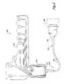
- FIG. 3shows an exploded view of the connector constructed according to the present invention
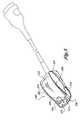
- FIG. 4shows a side plan view of the connector constructed according to the present invention
- FIG. 5shows a top perspective view of the connector constructed according to the present invention.
- FIG. 6shows a top plan view of an alternate embodiment of the connector constructed according to the present invention.
- FIG. 2shows a schematic illustration of a precordial electrocardiogram electrode system 200 , formed in accordance with the present invention.
- the system 200includes a disposable predodial electrode mask 100 , which may be constructed similar to that shown in FIGS. 1A and 1B, an electrode connector 202 , an electrocardiogram (ECG) device 206 , and a cable 208 from the connector 20 to the EGG device 206 .
- the cable 208includes a connector end 210 and an EGG device end 12 .
- the electrode mask 100may be supplied by Medtronic Physio-Control Corp. of Redmond, Wash.
- a suitable electrode mask 100is described in U.S. Pat. No. 6,006,125, the specification of which is herein incorporated by reference.
- the electrode mask 10includes a translucent substrate sheet 101 to which sensors, leads and electrode contacts can e attached to one side thereof, forming the conducting side. The opposite side of the conducting side forms the non-conducting side.
- the electrode mask 100also includes three locator cut outs 102 a, 102 b, 102 c, and labeling indicia (not shown) used to size the mask 100 for small, medium and large torsos.
- the electrode mask 100has a connecting portion 106 and a sensor portion 108 .
- the electrode mask 100includes a plurality of leads 110 terminating in electro e sensors 112 located in the sensor portion 108 and electrode contacts 114 locate in the connecting portion 106 of the electrode mask 100 .
- the locator cut-outs 102 a, 102 b, and 102 care suitably shaped for engagement to an electrode connector, formed n accordance with the present invention, thus allowing the electrode mask 100 to be selectively engaged to the electrode connector 202 for connecting a selected one of the three sets of six sensors to the EGG device 206 , depending on the torso size.
- electrode connectordesignates a device for connecting the electrode mask 100 to an EGG device 206 , such as an EGG monitor and/or defibrillator. Unless stated otherwise, “connector” will mean an “electrode connector.”
- the contacts 114 of the electrode mask 100are arranged in a predetermined manner wherein one of three sets of six electrode sensors 112 can be in contact with an electrode connector for the three corresponding torso sizes.
- the connecting portion 106can be considered to have six areas of contact 116 , 118 , 120 , 122 , 124 , and 126 . These distinct areas are defined to include a narrow strip of the contacting portion 106 having one or more electrode contacts 114 on the conducting side of the mask 100 and the non-conducting sheet 101 on the opposite side thereof, such that contact areas have both a conducting and non-conducting side.
- Contact areas 116 , 118 , 120 , and 122contain a single electrode contact 114 which substantially fills the contact area, respectively connected to sensors 112 a , 112 b , 112 c and 112 d .
- contact areas 124 and 126each have three distinct electrode contacts 114 .
- Contact area 124has contacts for sensors 112 e , 112 f , and 112 g
- contact area 126has contacts for sensors 112 g , 112 h , and 112 i .
- Sensor 112 g as notedhas contacts in two different contact areas 124 and 126 . From FIG.
- the electrode contacts 114 of contact areas 124 and 126are arranged in-line and separated by a gap of non-conducting material so as to electrically isolate the electrode contacts in contact areas 124 and 126 . Also apparent from FIG. 1B is the arrangement of locator cut-outs 102 in an in-line fashion. The distances between cut-outs 102 correspond to the distances separating electrode contacts in areas 124 and 126 .
- a locator pin 270as will be described in more detail below is inserted into one of the three locator cut-outs 102 , the amount of connecting portion 106 that is allowed to be inserted (i.e., depending on which cut-out 102 a , 102 b , or 102 c is placed over the locator pin) determines which of the three sets of electrodes is activated (i.e., enabled to send ECG signals to the ECG device).
- the connector 202makes contact with electrode contacts 114 in areas 116 , 118 , 120 , and 122 regardless of pin placement, but only makes contact with one of the three electrode contacts 114 in each of areas 124 and 126 depending on the pin placement.
- cut-out 102 athe upper contacts in areas 124 and 126 are selected corresponding to a small size torso; by selecting cut-out 102 b , the middle contacts in areas 124 and 126 are selected corresponding to a medium size torso selected; and by selecting cut-out 102 c , the lower contacts in areas 124 and 126 are selected corresponding to a large size torso. Contacts in areas 116 , 118 , 120 , and 122 are always to be selected regardless of cut-out selection.
- the ECG device 206 to which the electrode mask 100 is connectedis a defibrillator (not shown in detail) capable of monitoring ECG data as well as delivering a therapeutic shock.
- a defibrillatorknown as the LIFEPAK® 12 defibrillator
- the electrode connector 202is attached to the ECG device 206 via the cable 208 with a male/female assembly 216 on an end opposite the connector end 210 .
- the electrode connector 202constructed according to the present invention is illustrated in more detail to show its individual and internal components.
- the electrode connector 202includes an upper portion 218 having an electrode end 220 and an ECG end 222 , a lower or base portion 224 , likewise having an electrode end 226 and an ECG end 228 , and a spring 230 between the upper 218 and base portions 224 .
- electrode endand “ECG end” are meant to denote the relative alignment positions of the system components of FIG. 2 .
- the base portion 224further includes upper 232 and lower 234 base members.
- the lower member 234further includes an elastomeric covering 236 on a lower surface portion thereof, such as a thin urethane cover, to resist sliding off a patient's body.
- the urethane covercan be applied by well-known injection molding methods so that the elastomeric covering 236 and the lower member 234 form an integral unit.
- the elastomeric covering 236is detachably fastened to the lower member 234 .
- the electrode connector 202 of the present inventionfurther includes an electrical assembly 288 mounted between the upper 232 and lower 234 base members to provide electrical continuity between the electrode mask 204 and the ECG device 206 .
- the upper portion 218 of the connector 202includes an upper surface 286 contoured so as to resemble an arcuate shape.
- the upper portion 218also includes first 240 and second 242 buttressing walls located along the longitudinal sides of the connector's upper portion 218 .
- Buttressing walls 240 , 242are formed as downwardly extending sides from the upper portion top surface 286 .
- Buttress walls 240 , 242are considered “sides” of upper portion 218 .
- Buttressing walls 240 , 242include features to provide a suitable opening and closing arrangement between the connector's upper portion 218 and base 224 as will be described below.
- First and second buttress walls 240 , 242include pivotal axles 238 projecting outwardly or perpendicularly from the first 240 and second 242 buttress walls of the upper portion 218 , but mounted within a recessed portion 244 , wherein the recesses are formed on buttress walls 240 and 242 so that axles 238 minimally extend beyond the side surfaces of the upper portion 218 . While only a single axle is shown in FIG. 3, it should be readily apparent that the opposite side is configured similarly.
- the pivotal axles 238are located about one-third of the distance from the upper portion ECG end 222 .
- pivotal axlescan be located at any position along the outer length of the upper portion sides 240 and 242 , to provide a levering effect between the upper portion 218 and base portion 224 so as to provide an opening and closing motion of the upper and base portion ends 220 , 226 , respectively.
- pivoting axlesmay be located on the base portion rather than on the upper portion.
- the upper portionwould include apertures, or otherwise, to receive base portion axles.
- axlescan also be provided on the interior surfaces of buttress walls with corresponding apertures to receive the axles on the base portion.
- Other opening and closing configurationsare also possible without departing from the spirit and scope of the present invention. These alternates also form a part of this disclosure.
- the upper base member 232 of the base portion 224includes a first 246 and second (not shown) flange with openings 254 for engaging each of the respective pivotal axles 238 of the upper portion 218 therein and thereby attaching the upper portion 218 of the connector 202 with the base portion 224 . While only a single flange with opening combination is shown, it should be readily apparent that the opposite second flange and opening are configured similarly.
- the lower base member 234includes first 250 and second 252 posts for supporting the pivotal axles 238 on grooves 251 , 253 , therein. The posts 250 , 252 also provide securement against the axles 238 disengaging from the base portion 224 by blocking the openings 254 of the flanges 246 when the connector 202 is assembled.
- a spring 230is located between the upper portion 218 and the upper base member 232 to bias the ECG end 222 of the upper portion 218 upwards, thereby biasing the electrode end 220 downwards and towards the base portion upper member 232 , about the axles 238 .
- This spring 230is suitably constructed from metal, and preferably is formed into a folded “leaf” style spring. However, it is readily apparent that other spring devices can be used, such as coils and/or elastomeric materials to bias the upper and base portions, respectively, towards each other to form a clamping device.
- the spring 230is secured to a spring post (not shown) projecting downwardly from the lower surface 260 of the upper portion 218 .
- the spring 230has a cut-out portion 262 .
- the cut-out portion 262resembles an “H” shape, thus creating a flexible first and second flap 264 , 266 , which allows the spring 230 to be slid upward in the direction of arrow 267 onto the post but resists movement in the opposite direction, thusly securing the spring to the post.
- the upper portion 218 of the connector 202includes an indentation 268 located off-center of the longitudinal mid-axis of the upper portion electrode end 220 .
- the indentationprovides a partial “viewing window” to the electrode mask underneath when engaged with the connector 202 .
- a locator pin 270protrudes from the upper surface 272 of the upper member 232 of the base portion 224 .
- the locator pin 270is sized to fit within the electrode locator cut-outs or “pin holes” 102 of the electrode mask 100 shown in more detail in FIGS. 1A and 1B.
- the locator pin 270has the shape of a polyhedron, having four sides, so as to match the shape of the locator cut-outs 102 of the electrode mask 100 .
- the electrode end side 274 of the locator pin 270is shorter in width than its opposite ECG end side 276 .
- the first 278 and second 280 sides of the locator pin 270slope from the ECG end 276 side to the electrode end side 274 .
- the locator pin 270may be of any size and shape suitable for mating with the cut-outs of the electrode mask 100 .
- a portion of the locator pin ECG end side 276extends into the indentation 268 of the upper portion 218 of the connector 202 when the connector is closed as shown in FIG. 2, such that the sides of indentation 268 surround the pin 270 partially on three sides thereof.
- the electrode mask 100is thus prohibited from folding at the end of the upper portion electrode end, which would cause the electrode mask 100 to bend over and above the locator pin 270 , thus allowing the electrode mask 100 to slide out. Further, this configuration prohibits undesirable lateral movement of the electrode mask 100 .
- the locator pin 270is sized to accommodate any of the locator cut-outs 102 therein. As described above with reference to FIGS. 1A and 1B, each locator cut-out 102 in the electrode mask 100 labeled with an indicator which shows the appropriate torso size that is suitable to be use when the locator pin 270 is located within any particular locator cut-out 102 .
- the “sizing cut-out”determines which of the electrode contacts 114 , and thus, which of the nine sensors 112 will be active. For example, if a responder determines that a patient is of a size that warrants the use of a small electrode mask, the responder would place the electrode mask's connecting portion 106 at the appropriate locator cut-out 102 that corresponds to the size of the patient. By doing so, the appropriate electrode contacts 114 are lined up to receive and transmit ECG signals to the ECG device 206 .
- the upper member 232 of the base portion 224includes a first 282 and second 284 side extension rising upwards on opposite sides thereof.
- the side extensions 282 , 284are integral with the base portion upper member 232 and include the flanges 246 described above.
- the inner surfaces of side extensions 282 , 284lie adjacent and substantially parallel to first and second outer surfaces of wall buttresses 240 , 242 of the connector's upper portion 218 . Accordingly, when closed, the top surface 286 of the upper portion 218 is substantially flush with the base side extensions 282 , 284 .
- An electrical assembly 288is also shown in FIG. 3 forming a part of the electrode connector 202 .
- the electrical assembly 288is used to continue the electrical signals from the electrode mask 204 through the connector 202 and to the ECG device 206 as illustrated in the system of FIG. 2 .
- the electrical assembly 288includes an elastomeric electrical connector 290 , and a printed circuit board 292 with electrical components 294 mounted on a lower surface thereof.
- the printed circuit board 292includes a plurality of electrode contact pads 300 on the upper surface thereof.
- the electrical assembly 288is connected to the cable 208 at the connector end 210 with a female electrical connector (not shown) mounted on the underside of the printed circuit board 292 while the cable 208 carries a male adapter (not shown) at the corresponding connector end 210 .
- the cable 208includes a collar 306 with a groove which fits into an opening 229 of the lower base member 234 at ECG end 228 .
- the electrical components 294 on the printed circuit board 292form part of the electrical circuit between mask 100 and the ECG device 206 and are included to provide protection against device overload, as well as electrical shock to the users of the ECG device 206 or associated equipment. Such circuitry is well known in the art and has been included in previous connectors as a safety measure.
- the ECG signalstravel from the electrode mask 100 through the connector 202 through the electrical components 294 , thus forming an electrical circuit.
- Each of the six circuits that begins at the electrode contact areas 116 , 118 , 120 , 122 , 124 , and 126 and that ends at the ECG device 206is provided with a resistor 294 in the circuit.
- the resistors 294are suitably rated to operate under normal loads; however, if a spike in the voltage is detected, the resistors 294 limit the amount of current that passes through the circuit to a safe level, thus preventing high loads from reaching the ECG device 206 .
- the safe levelhas been determined by experience, experimentation, and with thought to the intended use of the connector.
- the resistors 294are suitably rated for a resistance of 51 kilo ⁇ ; however, other sizes are suitable depending on the circumstances in which the electrode mask and the ECG device are being used.
- the circuits of the electrode connector 202are also designed to protect their users. For example, if a patient were to experience cardiac arrest while the electrode mask is attached to the electrode connector, therapeutic shock delivery devices may be placed on the patient while the electrode mask is still connected. If the patient is shocked, the circuits are designed to limit the current passing through the electrode connector 202 in the manner just described, thus preventing an unacceptably high amount of current from reaching any person in contact with the electrode connector 202 or the ECG device 206 .
- the elastomer electrical connector 290is mounted to the base upper member 232 of the base portion 218 so as to make contact with the electrical contacts 300 of the printed circuit board 292 lying underneath. More specifically, the elastomeric connector 290 project through a slot 273 in the surface 272 of the upper member 232 .
- the underside of the connector's upper portion 218contains six ribs 299 a-f to press downward on the elastomeric connector 290 , protruding through the upper member 232 of the base portion 224 , at predetermined positions that correlate to the contact areas of the electrode mask 100 to provide a reliable and misalignment tolerant connection to the electrode mask 100 of FIG. 1 A.
- the elastomeric connector 290is supplied by numerous vendors, such as the Advanced Connector Technology Corp. of Camarillo, Calif. or the Fujipoly America Corp. of Kenilworth, N.J.
- the elastomeric connector 290is sometimes sold under the trademark ZEBRA®.
- the elastomeric connector 290includes alternating regions of conductive carbon-filled layers and non-conductive silicone layers.
- the advantage to having a flexible elastomeric connectoris that an elastomeric connector can be deflected and squeezed in between regular as well as irregular contacting surfaces.
- a suitable elastomeric connectoris the carbon elastomeric connector supplied by Fujipoly America Corp.
- the carbon modelcan have as little as 140 conductive layers per inch and as many as 500 conductive layers per inch. While elastomeric connectors are well known, their use in electrode connectors has not been disclosed.
- the six ribs(not shown) line up with the six contact areas 116 , 118 , 120 , 122 , 124 , and 126 on the non-conducting side thereof.
- each of the six ribswill come to overlie the connecting portion 106 of the mask 100 at one of the electrode contacts 114 located in each of the six contact areas.
- the electrode contacts 114 in the four contact areas 116 , 118 , 120 , and 122are continuously lined up regardless of the cut-out 102 selected because the electrode contacts 114 extend the whole length in these contact areas. However, the electrode contacts 114 in areas 124 and 126 are selectively lined up according to cut-out 102 selected because these areas have distinct unconnected electrode contacts 114 throughout the length of the contact area.
- the printed circuit board 292lies adjacent to the elastomeric connector 290 when the connector 202 is closed to provide for electrical continuity between the elastomeric electrical connector 290 engaged with the electrode contacts 114 of the electrode mask 100 and the ECG device 206 .
- the printed circuit board 292includes contact pads 300 , spatially located substantially corresponding to the ribs on the underside of the connector's upper portion 218 to make contact with the elastomeric electrical connector 290 .
- the electrode mask 100includes a plurality of contacts 114 which are placed in contact with the connector 202 of FIG. 3 via the elastomeric electrical connector 290 when the connector 202 is closed. Accordingly, depending on the size of the patient and thus, the selection of cut-out 102 a , 102 b , or 102 c placed over the locator pin 270 , six of the available sensors 112 are activated as described above, i.e., electrical signals from six of the sensors are conducted via the elastomeric electrical connector 290 to the electrical components 294 mounted on the printed circuit board 292 and ultimately to the ECG device 206 via the cable 208 as shown in FIG. 2 .
- the female adapterlocated on the printed circuit board 292 connects the printed circuit board 292 to the cable wires 304 attached to the connector end 210 of the cable 208 .
- a further connector assembly 216opposite the connector end 210 connects the connector 202 of the present invention to an ECG device 206 as shown in FIG. 2 .
- the electrode connector 202(or 202 ′ of FIG. 6) of the present invention is contoured and colored to be simple to use in actual operation. From a side perspective view, the electrode connector 202 has a curved downward sloping outline imparted by side extensions on base member 224 and to the upper portion 218 . The lower surface of the base 224 is generally flat. The profile of the electrode end 226 of the connector 202 is thus thinner than the profile of the connector ECG device end 228 . The advantage of this construction is to enable a responder to grasp the appropriate connector ends and securely position the connector on the appropriate electrode mask 100 pin hole 102 .
- the upper portion of the electrode connector 202 (or 202 ′) at the electrode end 220terminates before the base portion 224 at the base electrode end 226 thus, forming a ledge region 312 from the base upper surface 272 .
- An abrupt change in surface contours of the first and second side extensions 282 and 284 of the base portion 224forms suitable grasping points 316 and 318 for the connector 202 (or 202 ′).
- the grasping points 316 and 318are also bounded by outwardly projecting portions from the sides of the base portion 224 .
- the combination of curvilinear featuresprompts the responder to grasp the connector 202 (or 202 ′) in the most efficient and ergonomic manner.
- the unique contoursprevent the connector 202 (or 202 ′) from accidentally slipping out of the responder's hand.
- the connector 202 (or 202 ′)can become covered in body fluids as in many instances when defibrillator is employed by emergency teams and, thus, suitable grasping points are included.
- the electrode connector 202 made according to the present inventionis used in the following manner.
- An electrode mask 100is provided.
- the electrode connector 202is squeezed manually at the ECG ends 222 , 228 of the base and upper portion so as to provide an opening at the electrode ends 220 , 226 for insertion of the connecting portion 106 of the electrode mask 100 into the connector 220 .
- a locator cut-out 102is selected according to the patient's size (e.g., small, medium or large) and the locator pin 270 is located into the locator cut-out 102 .
- the pressure on the ECG ends 222 , 228 of the base 224 and the upper portion 218is released to allow the electrode ends 220 , 226 to close over and under the connecting portion 106 of the electrode mask 100 .
- the indentation 268 located on the upper portion electrode end 220partially surrounds the locator pin 270 .
- the sides of the indentation 268suitably overlap a portion of the locator pin 270 as seen from above in FIG. 5 (and FIG. 6 ).
- the electrode mask 100is held securely on the electrode connector 202 until the ECG ends 222 , 228 of the base 224 and upper portion 218 are again squeezed to open the electrode ends 220 , 226 and allow removal of the electrode mask 100 from the connector 202 .
- the electrical assembly 288operates in the following manner.
- the ribs (not shown) on the underside 260 of the upper connector's portion 218press on the non-conducting side of the contact areas 116 , 118 , 120 , 122 , 124 and 126 of the electrode mask 100 , which in turn presses the electrode contacts 114 against the elastomeric electrical connector 290 of the connector 202 , thus providing electrical continuity between the electrode mask 100 and the elastomeric connector 290 .
- the elastomeric connector 290is forcibly pushed against the printed circuit board pads 300 , thus providing electrical continuity between the elastomeric connector 290 and the board 292 .
- the board 292connects to the cable 208 via a plurality of wires 304 , eventually leading to the ECG device 206 .
- the use of an elastomeric electrical connector 290 in the electrical assembly 288provides for greater misalignment tolerance between the electrode contacts 114 and the connector 202 of the present invention.
- the upper portion 218 ′ of the connector 202 ′is of a different color than the base portion 224 assembly. This is to distinguish the moving upper portion 218 ′ from the stationary base portion 224 .
- the upper portion 218 ′is colored a matte gray color
- the base portion 224is a matte black color with a black urethane covering (shown in FIG. 3 as 236 ) on the lower surface portion of the base 224 to match the base color.
- a two-tone color scheme for the upper portion 218 ′ and the base portion 224provides for numerous advantages.
- the upper portion 218 ′includes a pigmentation of a different color than the base portion 224 so as to distinguish the upper portion 218 ′ as the piece which is to be depressed.
Landscapes
- Health & Medical Sciences (AREA)
- Life Sciences & Earth Sciences (AREA)
- Engineering & Computer Science (AREA)
- Medical Informatics (AREA)
- Surgery (AREA)
- Biophysics (AREA)
- Biomedical Technology (AREA)
- Heart & Thoracic Surgery (AREA)
- Physics & Mathematics (AREA)
- Molecular Biology (AREA)
- Pathology (AREA)
- Animal Behavior & Ethology (AREA)
- General Health & Medical Sciences (AREA)
- Public Health (AREA)
- Veterinary Medicine (AREA)
- Microelectronics & Electronic Packaging (AREA)
- Cardiology (AREA)
- Measurement And Recording Of Electrical Phenomena And Electrical Characteristics Of The Living Body (AREA)
Abstract
Description
Claims (40)
Priority Applications (1)
| Application Number | Priority Date | Filing Date | Title |
|---|---|---|---|
| US09/972,026US6623312B2 (en) | 2001-10-04 | 2001-10-04 | Precordial electrocardiogram electrode connector |
Applications Claiming Priority (1)
| Application Number | Priority Date | Filing Date | Title |
|---|---|---|---|
| US09/972,026US6623312B2 (en) | 2001-10-04 | 2001-10-04 | Precordial electrocardiogram electrode connector |
Publications (2)
| Publication Number | Publication Date |
|---|---|
| US20030068914A1 US20030068914A1 (en) | 2003-04-10 |
| US6623312B2true US6623312B2 (en) | 2003-09-23 |
Family
ID=25519066
Family Applications (1)
| Application Number | Title | Priority Date | Filing Date |
|---|---|---|---|
| US09/972,026Expired - LifetimeUS6623312B2 (en) | 2001-10-04 | 2001-10-04 | Precordial electrocardiogram electrode connector |
Country Status (1)
| Country | Link |
|---|---|
| US (1) | US6623312B2 (en) |
Cited By (56)
| Publication number | Priority date | Publication date | Assignee | Title |
|---|---|---|---|---|
| US20030228805A1 (en)* | 2002-06-07 | 2003-12-11 | Dieter Schwarz | Device for electrical connection of a power lead to an electrode, in particular a medical skin electrode |
| US20040176674A1 (en)* | 2003-03-04 | 2004-09-09 | Alireza Nazeri | EKG recording accessory system (EKG RAS) |
| US20040185709A1 (en)* | 2003-03-19 | 2004-09-23 | Williams Robert C. | Electrical connector apparatus, system and method for use with medical devices |
| US6814588B1 (en)* | 2001-12-05 | 2004-11-09 | Adaptec, Inc. | Overmold cable terminator |
| USD499488S1 (en) | 2003-05-20 | 2004-12-07 | Gmp Wireless Medicine, Inc. | Connector for wearable electrode connector assembly for ECG monitoring |
| US20050054232A1 (en)* | 2003-09-04 | 2005-03-10 | Naotaka Sasame | Cable connector |
| US20050113661A1 (en)* | 2003-11-21 | 2005-05-26 | Alireza Nazeri | EKG recording accessory system (EKG RAS) |
| US20050255739A1 (en)* | 2002-08-23 | 2005-11-17 | Nihon Kohden Corporation | Biological electrode and connector for the same |
| US20060259080A1 (en)* | 2005-03-21 | 2006-11-16 | Defibtech, Llc | System and method for presenting defibrillator status information while in standby mode |
| US20070073175A1 (en)* | 2005-09-29 | 2007-03-29 | Welch Allyn, Inc. | Galvanic isolation of a medical apparatus |
| US20070260133A1 (en)* | 2006-05-08 | 2007-11-08 | Tycohealthcare Group Lp | Radial electrode array |
| US20080081954A1 (en)* | 2006-09-28 | 2008-04-03 | Meyer Peter F | Cable monitoring apparatus |
| US20080082024A1 (en)* | 2006-09-28 | 2008-04-03 | Meyer Peter F | Signal replication medical apparatus |
| US20080083773A1 (en)* | 2004-08-20 | 2008-04-10 | Micinski Russell J | Contact Connector Assembly For A Sensor-Dispensing Instrument |
| US20080132106A1 (en)* | 2006-12-05 | 2008-06-05 | Lee Burnes | ECG lead set and ECG adapter system |
| US20080136652A1 (en)* | 2006-03-21 | 2008-06-12 | Defibtech, Llc | System and Method for Effectively Indicating Element Failure or a Preventive Maintenance Condition in an Automatic External Defibrillator (AED) |
| US20080139953A1 (en)* | 2006-11-01 | 2008-06-12 | Welch Allyn, Inc. | Body worn physiological sensor device having a disposable electrode module |
| US20080154110A1 (en)* | 2006-12-05 | 2008-06-26 | Lee Burnes | Electrode array |
| US20080177168A1 (en)* | 2006-12-05 | 2008-07-24 | Mark Callahan | Ecg lead wire organizer and dispenser |
| US20090088652A1 (en)* | 2007-09-28 | 2009-04-02 | Kathleen Tremblay | Physiological sensor placement and signal transmission device |
| US20090143663A1 (en)* | 2005-07-01 | 2009-06-04 | Impedance Cardiology Systems Inc. | Pulmonary Monitoring System |
| US7548781B2 (en) | 2005-03-21 | 2009-06-16 | Defibtech, Llc | Environmentally responsive active status indicator system and method |
| US20090187225A1 (en)* | 2005-03-21 | 2009-07-23 | Defibtech, Llc | PCB blade connector system and method |
| US20090242240A1 (en)* | 2008-03-27 | 2009-10-01 | Fujifilm Corporation | Flexible circuit board, flexible circuit board positioning method, flexible circuit board positioning structure, droplet ejection head and image forming device |
| WO2010132923A1 (en)* | 2009-05-18 | 2010-11-25 | Impedimed Limited | Electrode assembly |
| USD639243S1 (en) | 2006-03-29 | 2011-06-07 | Nuvasive, Inc. | Electrode connector |
| US20110230066A1 (en)* | 2010-03-16 | 2011-09-22 | Nihon Kohden Corporation | Connector, card edge connector, and sensor using the same |
| JP2012106141A (en)* | 2005-07-01 | 2012-06-07 | Impedimed Ltd | Monitoring system |
| US8233974B2 (en) | 1999-06-22 | 2012-07-31 | Impedimed Limited | Method and device for measuring tissue oedema |
| US8487686B2 (en) | 2007-03-30 | 2013-07-16 | Impedimed Limited | Active guarding for reduction of resistive and capacitive signal loading with adjustable control of compensation level |
| US8568160B2 (en) | 2010-07-29 | 2013-10-29 | Covidien Lp | ECG adapter system and method |
| US8690611B2 (en) | 2007-12-11 | 2014-04-08 | Covidien Lp | ECG electrode connector |
| US8694080B2 (en) | 2009-10-21 | 2014-04-08 | Covidien Lp | ECG lead system |
| US8761870B2 (en) | 2006-05-30 | 2014-06-24 | Impedimed Limited | Impedance measurements |
| US8836345B2 (en) | 2007-11-05 | 2014-09-16 | Impedimed Limited | Impedance determination |
| CN104659507A (en)* | 2013-11-22 | 2015-05-27 | 特克特朗尼克公司 | High performance LIGA spring interconnect system for probing application |
| CN104659624A (en)* | 2013-11-22 | 2015-05-27 | 特克特朗尼克公司 | High performance multiport connector system using LIGA springs |
| USD737979S1 (en) | 2008-12-09 | 2015-09-01 | Covidien Lp | ECG electrode connector |
| US9149235B2 (en) | 2004-06-18 | 2015-10-06 | Impedimed Limited | Oedema detection |
| US9226680B1 (en) | 2013-02-12 | 2016-01-05 | David Kendricks | Patient electrode connectors for electrocardiograph monitoring system |
| US9392947B2 (en) | 2008-02-15 | 2016-07-19 | Impedimed Limited | Blood flow assessment of venous insufficiency |
| US9408547B2 (en) | 2011-07-22 | 2016-08-09 | Covidien Lp | ECG electrode connector |
| US9408546B2 (en) | 2013-03-15 | 2016-08-09 | Covidien Lp | Radiolucent ECG electrode system |
| USD771818S1 (en) | 2013-03-15 | 2016-11-15 | Covidien Lp | ECG electrode connector |
| US9504406B2 (en) | 2006-11-30 | 2016-11-29 | Impedimed Limited | Measurement apparatus |
| US9585593B2 (en) | 2009-11-18 | 2017-03-07 | Chung Shing Fan | Signal distribution for patient-electrode measurements |
| US9615766B2 (en) | 2008-11-28 | 2017-04-11 | Impedimed Limited | Impedance measurement process |
| US9615767B2 (en) | 2009-10-26 | 2017-04-11 | Impedimed Limited | Fluid level indicator determination |
| US9693701B2 (en) | 2013-03-15 | 2017-07-04 | Covidien Lp | Electrode connector design to aid in correct placement |
| US9700223B2 (en) | 2011-12-02 | 2017-07-11 | Lumiradx Uk Ltd | Method for forming a component of a wearable monitor |
| US9724012B2 (en) | 2005-10-11 | 2017-08-08 | Impedimed Limited | Hydration status monitoring |
| US9734304B2 (en) | 2011-12-02 | 2017-08-15 | Lumiradx Uk Ltd | Versatile sensors with data fusion functionality |
| US10307074B2 (en) | 2007-04-20 | 2019-06-04 | Impedimed Limited | Monitoring system and probe |
| US10702176B2 (en) | 2014-08-22 | 2020-07-07 | Children's Medical Center Corporation | Multielectrode ECG sensor |
| WO2021072164A1 (en)* | 2019-10-10 | 2021-04-15 | Ripple, LLC | Systems and methods for coupling electrodes and electrical components |
| US11660013B2 (en) | 2005-07-01 | 2023-05-30 | Impedimed Limited | Monitoring system |
Families Citing this family (18)
| Publication number | Priority date | Publication date | Assignee | Title |
|---|---|---|---|---|
| US7917228B2 (en)* | 2003-05-13 | 2011-03-29 | Medtronic, Inc. | Medical lead adaptor assembly |
| US7214107B2 (en)* | 2004-11-22 | 2007-05-08 | Cardiodynamics International Corporation | Electrical connector apparatus and methods |
| AU2013237641B2 (en)* | 2006-12-05 | 2015-11-19 | Kpr U.S., Llc | ECG lead set and ECG adapter system |
| RU2501521C2 (en)* | 2008-02-29 | 2013-12-20 | Конинклейке Филипс Электроникс, Н.В. | Edge connector without fastening elements for medical control, compatible with magnetic resonance equipment |
| US9420962B2 (en) | 2008-04-30 | 2016-08-23 | Medtronic, Inc. | Remote lead implant testing |
| US8214045B2 (en) | 2008-04-30 | 2012-07-03 | Medtronic, Inc. | Lead implant system |
| US7563142B1 (en) | 2008-04-30 | 2009-07-21 | Medtronic, Inc. | Medical device packaging systems including electrical interfaces |
| US7953495B2 (en) | 2008-04-30 | 2011-05-31 | Medtronic, Inc. | Lead-implant coupling device |
| US7950971B2 (en)* | 2008-08-08 | 2011-05-31 | Cardiodynamics International Corporation | Electrical connector apparatus and methods |
| US20130023750A1 (en)* | 2011-07-22 | 2013-01-24 | Tyco Healthcare Group Lp | Ecg electrode system |
| DE202012001645U1 (en)* | 2012-02-17 | 2013-05-21 | Rosenberger Hochfrequenztechnik Gmbh & Co. Kg | Device for contacting a printed circuit board |
| TWM524692U (en)* | 2016-02-17 | 2016-07-01 | Wandy Rubber Ind Co Ltd | Electrical transmission sensing chip device |
| JP6504547B2 (en)* | 2016-08-05 | 2019-04-24 | 株式会社心電技術研究所 | ECG measurement device |
| KR101999826B1 (en)* | 2018-01-24 | 2019-07-12 | 주식회사 유니메딕스 | Electrocardiogram electrode connector |
| GB201810670D0 (en)* | 2018-06-28 | 2018-08-15 | Bare Conductive Ltd | Sensor and electrical connector |
| WO2021130683A1 (en)* | 2019-12-23 | 2021-07-01 | Alimetry Limited | Electrode patch and connection system |
| CN112587143B (en)* | 2020-12-29 | 2025-02-25 | 江苏正心智能科技有限公司 | A sensor device |
| US20240033494A1 (en)* | 2021-02-06 | 2024-02-01 | Joesph M. Bunch | Apparatus for Accurately Positioning an Endocaval Lead |
Citations (26)
| Publication number | Priority date | Publication date | Assignee | Title |
|---|---|---|---|---|
| US4151462A (en)* | 1977-04-13 | 1979-04-24 | Teyler A Lee | Electrical test probe having a spring biased clip with an extendable and retractable tip movable within the clip |
| US4353372A (en) | 1980-02-11 | 1982-10-12 | Bunker Ramo Corporation | Medical cable set and electrode therefor |
| US4653503A (en) | 1983-11-23 | 1987-03-31 | R2 Corporation | Physiological electrodes for use with magnetic connector |
| US4671591A (en) | 1985-07-15 | 1987-06-09 | Physio-Control Corporation | Electrical connector |
| US4702256A (en) | 1984-10-24 | 1987-10-27 | Andover Medical Incorporated | Electrical connector for a disposable electrode |
| US4773424A (en) | 1985-10-02 | 1988-09-27 | Fukuda Denshi Co., Ltd. | Electrocardiographic electrode |
| US4776350A (en) | 1986-01-07 | 1988-10-11 | Physio-Control Corporation | External electrode for heart stimulation and connector therefor |
| US5058589A (en) | 1985-03-20 | 1991-10-22 | Arbo Medizin-Technologie Gmbh | Electrode for measuring body currents |
| US5176543A (en) | 1992-03-12 | 1993-01-05 | Spacelabs, Inc. | Universal connector apparatus |
| US5191886A (en) | 1991-04-18 | 1993-03-09 | Physio-Control Corporation | Multiple electrode strip |
| US5277613A (en)* | 1992-05-18 | 1994-01-11 | Neward Theodore C | Electrode junction assembly |
| US5341806A (en) | 1991-04-18 | 1994-08-30 | Physio-Control Corporation | Multiple electrode strip |
| US5355883A (en) | 1991-12-27 | 1994-10-18 | Gilles Ascher | Electrode connector, in particular for electrocardiogram electrodes, and electrode assembly comprising a connector of this kind |
| US5372125A (en) | 1993-08-13 | 1994-12-13 | Ludlow Corporation | Positive locking biomedical electrode and connector system |
| US5405273A (en)* | 1991-04-24 | 1995-04-11 | Ndm Acquisition Corp. | Medical electrode assembly |
| US5582180A (en) | 1994-11-04 | 1996-12-10 | Physio-Control Corporation | Combination three-twelve lead electrocardiogram cable |
| US5788516A (en)* | 1994-04-05 | 1998-08-04 | Telefonaktiebolaget Lm Ericsson | Elastomeric connector |
| US5791944A (en) | 1996-06-18 | 1998-08-11 | Cambridge Heart, Inc. | Electrode connector |
| US5797771A (en)* | 1996-08-16 | 1998-08-25 | U.S. Robotics Mobile Communication Corp. | Cable connector |
| US5895369A (en)* | 1994-09-30 | 1999-04-20 | Becton Dickinson And Company | Iontophoresis patch/controller interconnection using a conductive elastomer to provide noise-free electrical contact between patch and controller |
| US5967817A (en) | 1995-11-21 | 1999-10-19 | Heartstream, Inc. | Medical connector apparatus |
| US6062915A (en)* | 1999-02-05 | 2000-05-16 | Iomed, Inc. | Nondeforming electrode connector |
| US6152754A (en)* | 1999-12-21 | 2000-11-28 | Masimo Corporation | Circuit board based cable connector |
| US6223088B1 (en)* | 1998-11-09 | 2001-04-24 | Katecho, Incorporated | Electrode and connector assembly and method for using same |
| USD452318S1 (en) | 2001-02-22 | 2001-12-18 | Medtronic Physio-Control Manufacturing Corp. | Electrode connector |
| US6357089B1 (en)* | 1998-02-24 | 2002-03-19 | Sekisui Plastics Co., Ltd. | Clip for a sheet electrode |
- 2001
- 2001-10-04USUS09/972,026patent/US6623312B2/ennot_activeExpired - Lifetime
Patent Citations (27)
| Publication number | Priority date | Publication date | Assignee | Title |
|---|---|---|---|---|
| US4151462A (en)* | 1977-04-13 | 1979-04-24 | Teyler A Lee | Electrical test probe having a spring biased clip with an extendable and retractable tip movable within the clip |
| US4353372A (en) | 1980-02-11 | 1982-10-12 | Bunker Ramo Corporation | Medical cable set and electrode therefor |
| US4653503A (en) | 1983-11-23 | 1987-03-31 | R2 Corporation | Physiological electrodes for use with magnetic connector |
| US4702256A (en) | 1984-10-24 | 1987-10-27 | Andover Medical Incorporated | Electrical connector for a disposable electrode |
| US5058589A (en) | 1985-03-20 | 1991-10-22 | Arbo Medizin-Technologie Gmbh | Electrode for measuring body currents |
| US4671591A (en) | 1985-07-15 | 1987-06-09 | Physio-Control Corporation | Electrical connector |
| US4773424A (en) | 1985-10-02 | 1988-09-27 | Fukuda Denshi Co., Ltd. | Electrocardiographic electrode |
| US4776350A (en) | 1986-01-07 | 1988-10-11 | Physio-Control Corporation | External electrode for heart stimulation and connector therefor |
| US5341806A (en) | 1991-04-18 | 1994-08-30 | Physio-Control Corporation | Multiple electrode strip |
| US5191886A (en) | 1991-04-18 | 1993-03-09 | Physio-Control Corporation | Multiple electrode strip |
| US5405273A (en)* | 1991-04-24 | 1995-04-11 | Ndm Acquisition Corp. | Medical electrode assembly |
| US5355883A (en) | 1991-12-27 | 1994-10-18 | Gilles Ascher | Electrode connector, in particular for electrocardiogram electrodes, and electrode assembly comprising a connector of this kind |
| US5176543A (en) | 1992-03-12 | 1993-01-05 | Spacelabs, Inc. | Universal connector apparatus |
| US5277613A (en)* | 1992-05-18 | 1994-01-11 | Neward Theodore C | Electrode junction assembly |
| US5372125A (en) | 1993-08-13 | 1994-12-13 | Ludlow Corporation | Positive locking biomedical electrode and connector system |
| US5788516A (en)* | 1994-04-05 | 1998-08-04 | Telefonaktiebolaget Lm Ericsson | Elastomeric connector |
| US5895369A (en)* | 1994-09-30 | 1999-04-20 | Becton Dickinson And Company | Iontophoresis patch/controller interconnection using a conductive elastomer to provide noise-free electrical contact between patch and controller |
| US5582180A (en) | 1994-11-04 | 1996-12-10 | Physio-Control Corporation | Combination three-twelve lead electrocardiogram cable |
| US6048218A (en) | 1995-11-21 | 2000-04-11 | Heartstream, Inc. | Medical connector apparatus |
| US5967817A (en) | 1995-11-21 | 1999-10-19 | Heartstream, Inc. | Medical connector apparatus |
| US5791944A (en) | 1996-06-18 | 1998-08-11 | Cambridge Heart, Inc. | Electrode connector |
| US5797771A (en)* | 1996-08-16 | 1998-08-25 | U.S. Robotics Mobile Communication Corp. | Cable connector |
| US6357089B1 (en)* | 1998-02-24 | 2002-03-19 | Sekisui Plastics Co., Ltd. | Clip for a sheet electrode |
| US6223088B1 (en)* | 1998-11-09 | 2001-04-24 | Katecho, Incorporated | Electrode and connector assembly and method for using same |
| US6062915A (en)* | 1999-02-05 | 2000-05-16 | Iomed, Inc. | Nondeforming electrode connector |
| US6152754A (en)* | 1999-12-21 | 2000-11-28 | Masimo Corporation | Circuit board based cable connector |
| USD452318S1 (en) | 2001-02-22 | 2001-12-18 | Medtronic Physio-Control Manufacturing Corp. | Electrode connector |
Cited By (122)
| Publication number | Priority date | Publication date | Assignee | Title |
|---|---|---|---|---|
| US8233974B2 (en) | 1999-06-22 | 2012-07-31 | Impedimed Limited | Method and device for measuring tissue oedema |
| US6814588B1 (en)* | 2001-12-05 | 2004-11-09 | Adaptec, Inc. | Overmold cable terminator |
| US20030228805A1 (en)* | 2002-06-07 | 2003-12-11 | Dieter Schwarz | Device for electrical connection of a power lead to an electrode, in particular a medical skin electrode |
| US6780065B2 (en)* | 2002-06-07 | 2004-08-24 | Nicolay Verwaltungs-Gmbh | Device for electrical connection of a power lead to an electrode, in particular a medical skin electrode |
| US7749013B2 (en)* | 2002-08-23 | 2010-07-06 | Nihon Kohden Corporation | Biological electrode and connector for the same |
| US20050255739A1 (en)* | 2002-08-23 | 2005-11-17 | Nihon Kohden Corporation | Biological electrode and connector for the same |
| US20040176674A1 (en)* | 2003-03-04 | 2004-09-09 | Alireza Nazeri | EKG recording accessory system (EKG RAS) |
| US7444177B2 (en) | 2003-03-04 | 2008-10-28 | Alireza Nazeri | EKG recording accessory system (EKG RAS) |
| US20040185709A1 (en)* | 2003-03-19 | 2004-09-23 | Williams Robert C. | Electrical connector apparatus, system and method for use with medical devices |
| USD499488S1 (en) | 2003-05-20 | 2004-12-07 | Gmp Wireless Medicine, Inc. | Connector for wearable electrode connector assembly for ECG monitoring |
| US7077684B2 (en)* | 2003-09-04 | 2006-07-18 | Tyco Electronics Amp K.K. | Cable connector |
| US20050054232A1 (en)* | 2003-09-04 | 2005-03-10 | Naotaka Sasame | Cable connector |
| US20050113661A1 (en)* | 2003-11-21 | 2005-05-26 | Alireza Nazeri | EKG recording accessory system (EKG RAS) |
| US9149235B2 (en) | 2004-06-18 | 2015-10-06 | Impedimed Limited | Oedema detection |
| US20080293278A1 (en)* | 2004-08-20 | 2008-11-27 | Bayer Healthcare Llc | Contact connector assembly for a sensor-dispensing instrument |
| US20080083773A1 (en)* | 2004-08-20 | 2008-04-10 | Micinski Russell J | Contact Connector Assembly For A Sensor-Dispensing Instrument |
| US7575457B2 (en) | 2004-08-20 | 2009-08-18 | Bayer Healthcare Llc | Contact connector assembly for a sensor-dispensing instrument |
| US7416430B2 (en)* | 2004-08-20 | 2008-08-26 | Bayer Healthcare Llc | Contact connector assembly for a sensor-dispensing instrument |
| US8774916B2 (en) | 2005-03-21 | 2014-07-08 | Defibtech, Llc | PCB blade connector system and method |
| US7627372B2 (en) | 2005-03-21 | 2009-12-01 | Defibtech, Llc | System and method for presenting defibrillator status information while in standby mode |
| US7912543B2 (en) | 2005-03-21 | 2011-03-22 | Defibtech, Llc | PCB blade connector system and method |
| US8280506B2 (en) | 2005-03-21 | 2012-10-02 | Defibtech, Llc | PCB blade connector system and method |
| US20060259080A1 (en)* | 2005-03-21 | 2006-11-16 | Defibtech, Llc | System and method for presenting defibrillator status information while in standby mode |
| US7953478B2 (en) | 2005-03-21 | 2011-05-31 | Defibtech, Llc | System and method for presenting defibrillator status information while in standby mode |
| US8185197B2 (en) | 2005-03-21 | 2012-05-22 | Defibtech, Llc | Identifying the usage status of a defibrillation pad assembly |
| US20100069981A1 (en)* | 2005-03-21 | 2010-03-18 | Defibtech, Llc | System and Method for Presenting Defibrillator Status Information While in Standby Mode |
| US7548781B2 (en) | 2005-03-21 | 2009-06-16 | Defibtech, Llc | Environmentally responsive active status indicator system and method |
| US20090187225A1 (en)* | 2005-03-21 | 2009-07-23 | Defibtech, Llc | PCB blade connector system and method |
| US20100168811A1 (en)* | 2005-03-21 | 2010-07-01 | Defibtech, Llc | Identifying the Usage Status of a Defibrillation Pad Assembly |
| US20090233458A1 (en)* | 2005-03-21 | 2009-09-17 | Defibtech, Llc | PCB blade connector system and method |
| US8185196B2 (en) | 2005-03-21 | 2012-05-22 | Defibtech, Llc | PCB blade connector system and method |
| US20110213262A1 (en)* | 2005-03-21 | 2011-09-01 | Defibtech, Llc | Method for Presenting Current and Stored ECG Waveforms on a Portable, External Defibrillator |
| JP2012106141A (en)* | 2005-07-01 | 2012-06-07 | Impedimed Ltd | Monitoring system |
| US20090143663A1 (en)* | 2005-07-01 | 2009-06-04 | Impedance Cardiology Systems Inc. | Pulmonary Monitoring System |
| US11660013B2 (en) | 2005-07-01 | 2023-05-30 | Impedimed Limited | Monitoring system |
| US11737678B2 (en) | 2005-07-01 | 2023-08-29 | Impedimed Limited | Monitoring system |
| US8781551B2 (en)* | 2005-07-01 | 2014-07-15 | Impedimed Limited | Apparatus for connecting impedance measurement apparatus to an electrode |
| US7618377B2 (en)* | 2005-09-29 | 2009-11-17 | Welch Allyn, Inc. | Galvanic isolation of a medical apparatus |
| US20070073175A1 (en)* | 2005-09-29 | 2007-03-29 | Welch Allyn, Inc. | Galvanic isolation of a medical apparatus |
| US9724012B2 (en) | 2005-10-11 | 2017-08-08 | Impedimed Limited | Hydration status monitoring |
| US11612332B2 (en) | 2005-10-11 | 2023-03-28 | Impedimed Limited | Hydration status monitoring |
| US8116863B2 (en) | 2006-03-21 | 2012-02-14 | Defibtech, Llc | System and method for effectively indicating element failure or a preventive maintenance condition in an automatic external defibrillator (AED) |
| US20110213433A1 (en)* | 2006-03-21 | 2011-09-01 | Defibtech, Llc | System and Method for Effectively Indicating Element Failure or a Preventive Maintenance Condition in an Automatic External Defibrillator (AED) |
| US8386035B2 (en) | 2006-03-21 | 2013-02-26 | Defibtech, Llc | System and method for effectively indicating element failure or a preventive maintenance condition in an automatic external defibrillator (AED) |
| US20080136652A1 (en)* | 2006-03-21 | 2008-06-12 | Defibtech, Llc | System and Method for Effectively Indicating Element Failure or a Preventive Maintenance Condition in an Automatic External Defibrillator (AED) |
| USD639741S1 (en) | 2006-03-29 | 2011-06-14 | Nuvasive, Inc. | Electrode connector |
| USD639243S1 (en) | 2006-03-29 | 2011-06-07 | Nuvasive, Inc. | Electrode connector |
| US7616980B2 (en) | 2006-05-08 | 2009-11-10 | Tyco Healthcare Group Lp | Radial electrode array |
| US20070260133A1 (en)* | 2006-05-08 | 2007-11-08 | Tycohealthcare Group Lp | Radial electrode array |
| US7925323B2 (en) | 2006-05-08 | 2011-04-12 | Tyco Healthcare Group Lp | Radial electrode array |
| US8761870B2 (en) | 2006-05-30 | 2014-06-24 | Impedimed Limited | Impedance measurements |
| US20080082024A1 (en)* | 2006-09-28 | 2008-04-03 | Meyer Peter F | Signal replication medical apparatus |
| US8821405B2 (en) | 2006-09-28 | 2014-09-02 | Covidien Lp | Cable monitoring apparatus |
| US8109883B2 (en) | 2006-09-28 | 2012-02-07 | Tyco Healthcare Group Lp | Cable monitoring apparatus |
| US20080081954A1 (en)* | 2006-09-28 | 2008-04-03 | Meyer Peter F | Cable monitoring apparatus |
| US10159422B2 (en) | 2006-11-01 | 2018-12-25 | Welch Allyn, Inc. | Body worn physiological sensor device having a disposable electrode module |
| US9877663B2 (en) | 2006-11-01 | 2018-01-30 | Welch Allyn, Inc. | Body worn physiological sensor device having a disposable electrode module |
| US9433366B2 (en)* | 2006-11-01 | 2016-09-06 | Welch Allyn, Inc. | Body worn physiological sensor device having a disposable electrode module |
| US8965492B2 (en) | 2006-11-01 | 2015-02-24 | Welch Allyn, Inc. | Body worn physiological sensor device having a disposable electrode module |
| US8214007B2 (en)* | 2006-11-01 | 2012-07-03 | Welch Allyn, Inc. | Body worn physiological sensor device having a disposable electrode module |
| US9155484B2 (en) | 2006-11-01 | 2015-10-13 | Welch Allyn, Inc. | Body worn physiological sensor device having a disposable electrode module |
| US20080139953A1 (en)* | 2006-11-01 | 2008-06-12 | Welch Allyn, Inc. | Body worn physiological sensor device having a disposable electrode module |
| US8630699B2 (en) | 2006-11-01 | 2014-01-14 | Welch Allyn, Inc. | Body worn physiological sensor device having a disposable electrode module |
| US8750974B2 (en) | 2006-11-01 | 2014-06-10 | Welch Allyn, Inc. | Body worn physiological sensor device having a disposable electrode module |
| US9504406B2 (en) | 2006-11-30 | 2016-11-29 | Impedimed Limited | Measurement apparatus |
| US8571627B2 (en) | 2006-12-05 | 2013-10-29 | Covidien Lp | ECG lead wire organizer and dispenser |
| US8868152B2 (en) | 2006-12-05 | 2014-10-21 | Covidien Lp | Electrode array |
| US8180425B2 (en) | 2006-12-05 | 2012-05-15 | Tyco Healthcare Group Lp | ECG lead wire organizer and dispenser |
| US8668651B2 (en) | 2006-12-05 | 2014-03-11 | Covidien Lp | ECG lead set and ECG adapter system |
| US20080132106A1 (en)* | 2006-12-05 | 2008-06-05 | Lee Burnes | ECG lead set and ECG adapter system |
| US20080154110A1 (en)* | 2006-12-05 | 2008-06-26 | Lee Burnes | Electrode array |
| US20080177168A1 (en)* | 2006-12-05 | 2008-07-24 | Mark Callahan | Ecg lead wire organizer and dispenser |
| US20120226129A1 (en)* | 2006-12-05 | 2012-09-06 | Tyco Healthcare Group Lp | ECG Lead Wire Organizer And Dispenser |
| US8560043B2 (en)* | 2006-12-05 | 2013-10-15 | Covidien Lp | ECG lead wire organizer and dispenser |
| US8238996B2 (en) | 2006-12-05 | 2012-08-07 | Tyco Healthcare Group Lp | Electrode array |
| US9072444B2 (en) | 2006-12-05 | 2015-07-07 | Covidien Lp | ECG lead set and ECG adapter system |
| US8487686B2 (en) | 2007-03-30 | 2013-07-16 | Impedimed Limited | Active guarding for reduction of resistive and capacitive signal loading with adjustable control of compensation level |
| US10307074B2 (en) | 2007-04-20 | 2019-06-04 | Impedimed Limited | Monitoring system and probe |
| US20090088652A1 (en)* | 2007-09-28 | 2009-04-02 | Kathleen Tremblay | Physiological sensor placement and signal transmission device |
| US8798708B2 (en) | 2007-09-28 | 2014-08-05 | Covidien Lp | Physiological sensor placement and signal transmission device |
| US8836345B2 (en) | 2007-11-05 | 2014-09-16 | Impedimed Limited | Impedance determination |
| US8795004B2 (en) | 2007-12-11 | 2014-08-05 | Covidien, LP | ECG electrode connector |
| US9107594B2 (en) | 2007-12-11 | 2015-08-18 | Covidien Lp | ECG electrode connector |
| US8690611B2 (en) | 2007-12-11 | 2014-04-08 | Covidien Lp | ECG electrode connector |
| US9392947B2 (en) | 2008-02-15 | 2016-07-19 | Impedimed Limited | Blood flow assessment of venous insufficiency |
| US20090242240A1 (en)* | 2008-03-27 | 2009-10-01 | Fujifilm Corporation | Flexible circuit board, flexible circuit board positioning method, flexible circuit board positioning structure, droplet ejection head and image forming device |
| US9615766B2 (en) | 2008-11-28 | 2017-04-11 | Impedimed Limited | Impedance measurement process |
| USD737979S1 (en) | 2008-12-09 | 2015-09-01 | Covidien Lp | ECG electrode connector |
| AU2010251750B2 (en)* | 2009-05-18 | 2015-04-09 | Impedimed Limited | Electrode assembly |
| WO2010132923A1 (en)* | 2009-05-18 | 2010-11-25 | Impedimed Limited | Electrode assembly |
| US8897865B2 (en) | 2009-10-21 | 2014-11-25 | Covidien Lp | ECG lead system |
| US8694080B2 (en) | 2009-10-21 | 2014-04-08 | Covidien Lp | ECG lead system |
| US9615767B2 (en) | 2009-10-26 | 2017-04-11 | Impedimed Limited | Fluid level indicator determination |
| US9585593B2 (en) | 2009-11-18 | 2017-03-07 | Chung Shing Fan | Signal distribution for patient-electrode measurements |
| US20110230066A1 (en)* | 2010-03-16 | 2011-09-22 | Nihon Kohden Corporation | Connector, card edge connector, and sensor using the same |
| US8585427B2 (en)* | 2010-03-16 | 2013-11-19 | Nihon Kohden Corporation | Connector, card edge connector, and sensor using the same |
| US8568160B2 (en) | 2010-07-29 | 2013-10-29 | Covidien Lp | ECG adapter system and method |
| US9737226B2 (en) | 2011-07-22 | 2017-08-22 | Covidien Lp | ECG electrode connector |
| US9408547B2 (en) | 2011-07-22 | 2016-08-09 | Covidien Lp | ECG electrode connector |
| US11350880B2 (en) | 2011-12-02 | 2022-06-07 | Lumiradx Uk Ltd. | Health-monitor patch |
| US9734304B2 (en) | 2011-12-02 | 2017-08-15 | Lumiradx Uk Ltd | Versatile sensors with data fusion functionality |
| US10022061B2 (en) | 2011-12-02 | 2018-07-17 | Lumiradx Uk Ltd. | Health-monitor patch |
| US10695004B2 (en) | 2011-12-02 | 2020-06-30 | LumiraDX UK, Ltd. | Activity-dependent multi-mode physiological sensor |
| US9854986B2 (en) | 2011-12-02 | 2018-01-02 | Lumiradx Uk Ltd | Health-monitor patch |
| US9700222B2 (en) | 2011-12-02 | 2017-07-11 | Lumiradx Uk Ltd | Health-monitor patch |
| US9700223B2 (en) | 2011-12-02 | 2017-07-11 | Lumiradx Uk Ltd | Method for forming a component of a wearable monitor |
| US9226680B1 (en) | 2013-02-12 | 2016-01-05 | David Kendricks | Patient electrode connectors for electrocardiograph monitoring system |
| US11076791B2 (en) | 2013-02-12 | 2021-08-03 | Advantage Medical Electronics, Llc | Patient electrode connectors for electrocardiograph monitoring system |
| US11806151B2 (en)* | 2013-02-12 | 2023-11-07 | Advantage Medical Electronics, Llc | Patient electrode connectors for electrocardiograph monitoring system |
| US20210353199A1 (en)* | 2013-02-12 | 2021-11-18 | Advantage Medical Electronics, Llc | Patient electrode connectors for electrocardiograph monitoring system |
| US10010257B1 (en) | 2013-02-12 | 2018-07-03 | Advantage Medical Electronics, Llc | Patient electrode connectors for electrocardiograph monitoring system |
| US9814404B2 (en) | 2013-03-15 | 2017-11-14 | Covidien Lp | Radiolucent ECG electrode system |
| US9408546B2 (en) | 2013-03-15 | 2016-08-09 | Covidien Lp | Radiolucent ECG electrode system |
| US9693701B2 (en) | 2013-03-15 | 2017-07-04 | Covidien Lp | Electrode connector design to aid in correct placement |
| USD771818S1 (en) | 2013-03-15 | 2016-11-15 | Covidien Lp | ECG electrode connector |
| CN104659624A (en)* | 2013-11-22 | 2015-05-27 | 特克特朗尼克公司 | High performance multiport connector system using LIGA springs |
| CN104659507A (en)* | 2013-11-22 | 2015-05-27 | 特克特朗尼克公司 | High performance LIGA spring interconnect system for probing application |
| CN104659624B (en)* | 2013-11-22 | 2019-04-09 | 特克特朗尼克公司 | Using the connector system of the high-performance multiport of LIGA spring |
| US10702176B2 (en) | 2014-08-22 | 2020-07-07 | Children's Medical Center Corporation | Multielectrode ECG sensor |
| WO2021072164A1 (en)* | 2019-10-10 | 2021-04-15 | Ripple, LLC | Systems and methods for coupling electrodes and electrical components |
| US20220224030A1 (en)* | 2019-10-10 | 2022-07-14 | Ripple Llc | Systems and methods for coupling electrodes and electrical components |
| US12237603B2 (en)* | 2019-10-10 | 2025-02-25 | Ripple Llc | Systems and methods for coupling electrodes and electrical components |
Also Published As
| Publication number | Publication date |
|---|---|
| US20030068914A1 (en) | 2003-04-10 |
Similar Documents
| Publication | Publication Date | Title |
|---|---|---|
| US6623312B2 (en) | Precordial electrocardiogram electrode connector | |
| CA1292528C (en) | Electrical connector | |
| US4832608A (en) | Electrode belt adapter | |
| US5582180A (en) | Combination three-twelve lead electrocardiogram cable | |
| US6097987A (en) | External defibrillator electrode apparatus | |
| US4207904A (en) | Constant power density electrode adapted to be useful in bio-medical applications | |
| EP3473175B1 (en) | Ecg electrode connector | |
| EP0390400B1 (en) | Biomedical electrode and connector | |
| US9902028B2 (en) | External case for a wearable medical device | |
| KR20170115592A (en) | Connector assembly for medical sensors with pogo pins | |
| US20140170622A1 (en) | Training Pad Connector | |
| US20130023159A1 (en) | Cable connector | |
| US20170065200A1 (en) | Electrode assembly | |
| US4094571A (en) | Grounding cable clip | |
| US4848345A (en) | Connection circuit and method for using monitor/defibrillator | |
| US5713925A (en) | Adapter for isolating pacing and defibrillation signals | |
| US7689278B2 (en) | Identification system for defibrillator electrode package | |
| US7428433B2 (en) | Heart rate monitor assembly | |
| EP1746617A1 (en) | Control assembly with engagement detection means | |
| CA1268823A (en) | Electrode securement sheet | |
| JP7696352B2 (en) | Electrical connector and cover for simultaneously connecting epicardial wires, a bedside monitor and a temporary pacemaker | |
| US5442151A (en) | Button well compression seal assembly | |
| JPH05293177A (en) | Electric medical treatment apparatus |
Legal Events
| Date | Code | Title | Description |
|---|---|---|---|
| AS | Assignment | Owner name:UNILEAD INTERNATIONAL, CALIFORNIA Free format text:ASSIGNMENT OF ASSIGNORS INTEREST;ASSIGNORS:MERRY, RODNEY J.;MCGRATH, TOM;O'CONNOR, PAUL;AND OTHERS;REEL/FRAME:012527/0944;SIGNING DATES FROM 20011206 TO 20011228 | |
| STCF | Information on status: patent grant | Free format text:PATENTED CASE | |
| FEPP | Fee payment procedure | Free format text:PAYOR NUMBER ASSIGNED (ORIGINAL EVENT CODE: ASPN); ENTITY STATUS OF PATENT OWNER: LARGE ENTITY Free format text:PAYER NUMBER DE-ASSIGNED (ORIGINAL EVENT CODE: RMPN); ENTITY STATUS OF PATENT OWNER: LARGE ENTITY | |
| CC | Certificate of correction | ||
| FPAY | Fee payment | Year of fee payment:4 | |
| FPAY | Fee payment | Year of fee payment:8 | |
| FPAY | Fee payment | Year of fee payment:12 | |
| AS | Assignment | Owner name:CITIBANK, N.A., AS COLLATERAL AGENT, NEW YORK Free format text:FIRST LIEN SECURITY AGREEMENT;ASSIGNORS:PHYSIO-CONTROL, INC.;PHYSIO-CONTROL INTERNATIONAL, INC.;REEL/FRAME:037532/0828 Effective date:20150605 | |
| AS | Assignment | Owner name:CITIBANK, N.A., AS COLLATERAL AGENT, NEW YORK Free format text:SECOND LIEN SECURITY AGREEMENT;ASSIGNORS:PHYSIO-CONTROL, INC.;PHYSIO-CONTROL INTERNATIONAL, INC.;REEL/FRAME:037559/0601 Effective date:20150605 | |
| AS | Assignment | Owner name:PHYSIO-CONTROL INTERNATIONAL, INC., WASHINGTON Free format text:RELEASE BY SECURED PARTY;ASSIGNOR:CITIBANK, N.A.;REEL/FRAME:038378/0028 Effective date:20160405 Owner name:PHYSIO-CONTROL, INC., WASHINGTON Free format text:RELEASE BY SECURED PARTY;ASSIGNOR:CITIBANK, N.A.;REEL/FRAME:038379/0001 Effective date:20160405 Owner name:PHYSIO-CONTROL INTERNATIONAL, INC., WASHINGTON Free format text:RELEASE BY SECURED PARTY;ASSIGNOR:CITIBANK, N.A.;REEL/FRAME:038379/0001 Effective date:20160405 Owner name:PHYSIO-CONTROL, INC., WASHINGTON Free format text:RELEASE BY SECURED PARTY;ASSIGNOR:CITIBANK, N.A.;REEL/FRAME:038378/0028 Effective date:20160405 |