US6623227B2 - Drill screw for adjusting molding relative to an underlying wall - Google Patents
Drill screw for adjusting molding relative to an underlying wallDownload PDFInfo
- Publication number
- US6623227B2 US6623227B2US09/916,387US91638701AUS6623227B2US 6623227 B2US6623227 B2US 6623227B2US 91638701 AUS91638701 AUS 91638701AUS 6623227 B2US6623227 B2US 6623227B2
- Authority
- US
- United States
- Prior art keywords
- drill screw
- molding
- rotational direction
- drill
- rotated
- Prior art date
- Legal status (The legal status is an assumption and is not a legal conclusion. Google has not performed a legal analysis and makes no representation as to the accuracy of the status listed.)
- Expired - Fee Related
Links
- 238000000465mouldingMethods0.000titleabstractdescription86
- 238000000034methodMethods0.000claimsdescription11
- 239000007787solidSubstances0.000claimsdescription6
- 239000012778molding materialSubstances0.000claims6
- 239000002023woodSubstances0.000description12
- 239000000463materialSubstances0.000description5
- 238000003780insertionMethods0.000description4
- 230000037431insertionEffects0.000description4
- 238000005553drillingMethods0.000description3
- 238000009432framingMethods0.000description2
- 239000011499joint compoundSubstances0.000description2
- 229910000831SteelInorganic materials0.000description1
- 230000002457bidirectional effectEffects0.000description1
- 230000010485copingEffects0.000description1
- 238000012937correctionMethods0.000description1
- 230000008878couplingEffects0.000description1
- 238000010168coupling processMethods0.000description1
- 238000005859coupling reactionMethods0.000description1
- 238000012986modificationMethods0.000description1
- 230000004048modificationEffects0.000description1
- 230000037390scarringEffects0.000description1
- 238000007790scrapingMethods0.000description1
- 239000010959steelSubstances0.000description1
Images


Classifications
- F—MECHANICAL ENGINEERING; LIGHTING; HEATING; WEAPONS; BLASTING
- F16—ENGINEERING ELEMENTS AND UNITS; GENERAL MEASURES FOR PRODUCING AND MAINTAINING EFFECTIVE FUNCTIONING OF MACHINES OR INSTALLATIONS; THERMAL INSULATION IN GENERAL
- F16B—DEVICES FOR FASTENING OR SECURING CONSTRUCTIONAL ELEMENTS OR MACHINE PARTS TOGETHER, e.g. NAILS, BOLTS, CIRCLIPS, CLAMPS, CLIPS OR WEDGES; JOINTS OR JOINTING
- F16B5/00—Joining sheets or plates, e.g. panels, to one another or to strips or bars parallel to them
- F16B5/02—Joining sheets or plates, e.g. panels, to one another or to strips or bars parallel to them by means of fastening members using screw-thread
- F16B5/0216—Joining sheets or plates, e.g. panels, to one another or to strips or bars parallel to them by means of fastening members using screw-thread the position of the plates to be connected being adjustable
- F16B5/0233—Joining sheets or plates, e.g. panels, to one another or to strips or bars parallel to them by means of fastening members using screw-thread the position of the plates to be connected being adjustable allowing for adjustment perpendicular to the plane of the plates
- F—MECHANICAL ENGINEERING; LIGHTING; HEATING; WEAPONS; BLASTING
- F16—ENGINEERING ELEMENTS AND UNITS; GENERAL MEASURES FOR PRODUCING AND MAINTAINING EFFECTIVE FUNCTIONING OF MACHINES OR INSTALLATIONS; THERMAL INSULATION IN GENERAL
- F16B—DEVICES FOR FASTENING OR SECURING CONSTRUCTIONAL ELEMENTS OR MACHINE PARTS TOGETHER, e.g. NAILS, BOLTS, CIRCLIPS, CLAMPS, CLIPS OR WEDGES; JOINTS OR JOINTING
- F16B25/00—Screws that cut thread in the body into which they are screwed, e.g. wood screws
- F16B25/001—Screws that cut thread in the body into which they are screwed, e.g. wood screws characterised by the material of the body into which the screw is screwed
- F16B25/0031—Screws that cut thread in the body into which they are screwed, e.g. wood screws characterised by the material of the body into which the screw is screwed the screw being designed to be screwed into different materials, e.g. a layered structure or through metallic and wooden parts
- F—MECHANICAL ENGINEERING; LIGHTING; HEATING; WEAPONS; BLASTING
- F16—ENGINEERING ELEMENTS AND UNITS; GENERAL MEASURES FOR PRODUCING AND MAINTAINING EFFECTIVE FUNCTIONING OF MACHINES OR INSTALLATIONS; THERMAL INSULATION IN GENERAL
- F16B—DEVICES FOR FASTENING OR SECURING CONSTRUCTIONAL ELEMENTS OR MACHINE PARTS TOGETHER, e.g. NAILS, BOLTS, CIRCLIPS, CLAMPS, CLIPS OR WEDGES; JOINTS OR JOINTING
- F16B25/00—Screws that cut thread in the body into which they are screwed, e.g. wood screws
- F16B25/0036—Screws that cut thread in the body into which they are screwed, e.g. wood screws characterised by geometric details of the screw
- F16B25/0084—Screws that cut thread in the body into which they are screwed, e.g. wood screws characterised by geometric details of the screw characterised by geometric details of the tip
- F—MECHANICAL ENGINEERING; LIGHTING; HEATING; WEAPONS; BLASTING
- F16—ENGINEERING ELEMENTS AND UNITS; GENERAL MEASURES FOR PRODUCING AND MAINTAINING EFFECTIVE FUNCTIONING OF MACHINES OR INSTALLATIONS; THERMAL INSULATION IN GENERAL
- F16B—DEVICES FOR FASTENING OR SECURING CONSTRUCTIONAL ELEMENTS OR MACHINE PARTS TOGETHER, e.g. NAILS, BOLTS, CIRCLIPS, CLAMPS, CLIPS OR WEDGES; JOINTS OR JOINTING
- F16B25/00—Screws that cut thread in the body into which they are screwed, e.g. wood screws
- F16B25/10—Screws performing an additional function to thread-forming, e.g. drill screws or self-piercing screws
- F16B25/103—Screws performing an additional function to thread-forming, e.g. drill screws or self-piercing screws by means of a drilling screw-point, i.e. with a cutting and material removing action
Definitions
- This inventionrelates broadly to threaded screw-like articles. More particularly, this invention relates to a threaded device having a drilling tip.
- Moldingis often nailed to the walls of a room to provide an attractive border to the room. Molding along the wall adjacent the floor is called baseboard molding. Molding along a central portion of the wall is called chair rail molding, often used to prevent the back of a chair from scraping and scarring the wall.
- the molding provided around a ceilingis referred to as crown molding and is often applied between the wall and ceiling at an angle such that the profile, or contoured pattern, of the face side of the molding is directed into the room.
- Copingis the process whereby the end of one piece of molding is shaped to seat flushly against the face of another piece. This ensures that the two pieces of molding have an attractive appearance when joined at an inside corner. Yet, the walls at an inside corner are not always true. Moreover, referring to FIG.
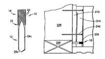
- the drywall 210 , 212 to which molding 214 , 216 is attachedincludes a taper 218 along its edges intended to be filled by tape and joint compound, collectively 220 .
- the tape and joint compoundis often not applied at a lower taper 222 of the drywall 210 , 212 . Therefore, when the bottom 224 of baseboard molding 214 is nailed to the bottom plate 226 (the horizontal wooden stud which runs along the floor) or the lower portion of a vertical stud 228 , the bottom 224 of the molding 214 gets “pulled in” at the location of the lower taper 222 of the drywall.
- a square cut end 232 , or a skillfully coped end, of piece of molding 216may not fit flushly against the “pulled in” adjoining molding piece 214 , resulting in a non-flush fit and gap 236 at the bottom of the inside corner.
- moldingis decorative, a finished appearance is very important to the building owner, as well as to the skilled and proud craftsman.
- the processis repeated until a suitable fit is obtained, and then the first piece of molding is re-nailed to the wall, with shim in place, and the second piece is nailed to the adjoining wall with its coped end flush against the first piece.
- Another method for correctionis to scribe the coped end of the molding for a proper fit against the “pulled in” molding, re-cut the coped molding along the scribe, and then re-cope the end of a piece of molding so that it fits flushly against the “pulled in” molding. Both methods are extremely labor intensive.
- a drill screwhaving a drill portion provided with cutting edges adapted to bore into wood when rotated in a first rotational direction (e.g., counterclockwise), a driver end opposite the drill portion, and a threaded portion between the drill portion and the driver end.
- the threaded portionis provided with threads adapted to tap into wood when rotated in a second rotational direction opposite the first rotational direction (e.g., clockwise).
- the driver endhas a diameter no greater the diameter of the threads (i.e., there is no head on the drill screw) to permit the driver end to be located below the surface of a piece of molding.
- the driver endis preferably provided with a hex opening adapted to receive an interference head of a driver, e.g., a hex bit, coupled to a preferably powered drill/driver.
- a drivere.g., a hex bit
- a first piece of moldingis coupled to drywall (or another wall type) which overlies a wooden stud structure (e.g., 2 ⁇ 4 stud framing over a bottom plate).
- a coped second piece of moldingis then coupled to an adjacent wall, with the coped end of the second piece of molding meeting the face of the first piece of molding at an inside corner defined by the walls. If the bottom face of the first piece of molding does not form a flush interface with the coped end, it is necessary to move the bottom end of the first piece toward the second piece at the corner to provide a clean look.
- the drill screw of the inventionis then driven in the first rotational direction to bore a hole at least through the bottom of the first piece of molding.
- the drill screwis then driven in the second rotational direction causing the threads to engage and tap into the molding.
- the drill screwsufficiently enters the molding a distance such that the end of the drill portion contacts the bottom plate (or stud)
- the drill screwrubs, but does not bore into (or further into) the bottom plate (or stud) in the clockwise direction.
- the molding around the drill screwis forced away from the drywall and toward the coped end of the adjoining molding, thereby closing the gap between the two pieces of molding and providing a clean molding interface at the corner.
- the moldingmust be forced over the head of the nails. This is possible, as the force of the drill screw overpowers the grip of the nails. Moreover, the top of the molding does not pull away from the wall at other locations to create a different unsightly gap. Once the gap is closed, the driver is removed from the driver end of the drill screw. The bore between the driver end of the drill screw and the surface of the first piece of molding is then filled with a wood fill or covered by a shoe molding for finishing.
- the drill screw of the inventionpermits both pieces of molding at a corner to be attached to the wall and then, if necessary, adjusted without removal of either piece of molding.
- the adjustmentis relatively quick, requiring only a single drill screw of the invention and a driver for the tool.
- FIG. 1is a side elevation view of a drill screw according to a first embodiment of the invention
- FIG. 2is a side elevation view of the drill screw of FIG. 1 taken 90° relative to the view of FIG. 1;
- FIG. 3is an end view of the driver portion of the drill screw of FIG. 1;
- FIG. 4is an end view of the drill portion of the drill screw of FIG. 1;
- FIG. 5is a side elevation view of a drill screw according to a second embodiment of the invention.
- FIG. 6is a side elevation view of the drill screw of FIG. 5 taken 90° relative to the view of FIG. 5;
- FIG. 7is an end view of the driver end of the drill screw of FIG. 5;
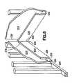
- FIG. 8illustrates the attachment of first and second pieces of molding at an inside corner and a gap formed therebetween
- FIGS. 9 through 11illustrate the use of the drill screw of the invention to adjust a first piece of molding relative to the second piece of molding to eliminate the gap.
- a first embodiment of a drill screw 10includes a drill portion 12 adapted to bore into wood when rotated counterclockwise (i.e., in a first rotational direction), and a threaded portion 18 provided with threads 20 adapted to tap into (threadably engage) wood when rotated clockwise (i.e., in a second rotational direction opposite the first rotational direction), and a transitional portion 22 therebetween.
- the drill portion 12preferably has a smaller diameter relative to the threaded portion 18 .
- the drill screwis preferably made from steel or another material from which a wood drill bit or wood screw is made from.
- the drill portion 12includes two concave flutes 24 a, 24 b each having a cutting edge 26 a, 26 b.
- a relief cut surface (or bevel) 28 a, 28 bis provided behind each cutting edge. This arrangement permits the cutting edge to enter fresh wood when rotated in the counterclockwise direction, but substantially prevents cutting when rotated in the clockwise direction. Rather, the drill portion rubs against, but does not cut, wood in the clockwise direction.
- the flutes 24 a, 24 boperate to remove cut material from the bored hole.
- the threaded portion 18has a driver end 30 for coupling with a tool adapted to rotate the drill screw 10 .
- the driver end 30has a diameter no greater than the diameter of the threads 20 ; i.e., there is no head on the drill screw.
- the driver endis preferably provided with an opening 32 adapted to receive an interference head of a driver, e.g., a hex opening adapted to receive a hex bit coupled to a preferably powered drill/driver.
- the threaded portion 18includes twenty threads per inch.
- Exemplar dimensions for the drill screw 10include: a total length of approximately 1.25 inches, a thread portion length of approximately 0.5 inch, a thread portion diameter of approximately 0.25 inch, a drill portion length of approximately 0.65 inch, a drill portion diameter of approximately 0.18 inch, and a transitional portion length of approximately 0.15 inch. These dimensions will provide a drill screw suitable for use in molding 0.75 inch and thinner. Of course, the drill screw may be provided in other sizes in order that it be adapted for use in thicker molding, or as preferred.
- the drill screw 110similarly includes a drill portion 112 and a threaded portion 118 .
- the drill portion 112generally includes two substantially planar sides 124 a, 124 b, each terminating in a cutting edge 126 a, 126 b.
- each cutting edge 126 a, 126 bis provided with an adjoining bevel 128 a, 128 b which permits the cutting edge to enter fresh wood when rotated in the counterclockwise direction, but substantially prevents cutting when rotated in the clockwise direction.
- the first and second embodimentsillustrate that various drill portion designs can be used. It is noted that any drill portion which bores in a first rotational direction, but not in an opposite second rotational direction, can be used.
- the drill screw 10 of the inventionwhen a gap 236 is present between two pieces of molding 214 , 216 at an inside corner (FIG. 8 ), the drill screw 10 of the invention is used to close the gap.
- the driver end 30 of the drill screw 10 of the inventionreceives a hex tool (not shown) (e.g., a hex bit coupled to a power drill capable of driving rotation in two directions) and is driven in a counterclockwise direction to cause the drill portion 12 to bore a hole 242 through the first piece of molding 214 until the threaded portion 18 of the drill screw 10 abuts the surface 244 of the molding (FIG. 9 ).
- the drill screw 10is then driven in the clockwise direction, preferably without necessitating decoupling the tool from the driver end of the drill screw.
- the threaded portion 18engages and taps into the molding 214 while the drill portion crumbles the drywall 210 (if present at the location of the drill screw) as a result of pressure applied (FIG. 10 ).
- the drill screw 10sufficiently enters the molding a distance such that the end of the drill portion 12 contacts the bottom plate 226 (or stud 228 ), it is noted that the drill screw rubs, but does not bore into the bottom plate (or stud) in the clockwise direction.
- the nail 246staying in place in the stud, but assuming a countersunk position in the molding 214 as shown in FIG. 11 .
- the top of the moldingdoes not pull away from the wall at other locations to create a different unsightly gap.
- the drill screw of the inventionpermits both pieces of molding at a corner to be attached to the wall and then, if necessary, adjusted without removal of either piece of molding.
- the adjustmentis relatively quick, requiring the insertion of a single drill screw according to the invention.
- the drill screwhas use beyond the fitting of molding, and may be used whenever a board needs to moved out from a surface and an object behind the surface is solid enough to resist the push of the screw.
- An additional exemplar useis to adjust the framing of a door jamb relative to the header and jackposts.
- a drilling portionsprovided with a spade portion, an auger portion, a bullet or pilot point, or a split point can also be used. That is, any cutting or boring means which creates a hole in a material when rotated in one rotational direction, but not the opposite rotational direction, and which is not substantially resisted from removal from the material; i.e., it is not adapted to become secured in the material, as a threaded screw would become secured.
- headless driving systemssuch as a square drive, could alternatively be used.
- a powered driverbe used to insert the drill screw
- the drill screwmay also be inserted manually using a tool, e.g., a hex wrench, which can provide bidirectional rotational force to the drill screw. It will therefore be appreciated by those skilled in the art that yet other modifications could be made to the provided invention without deviating from its spirit and scope as claimed.
Landscapes
- Engineering & Computer Science (AREA)
- General Engineering & Computer Science (AREA)
- Mechanical Engineering (AREA)
- Physics & Mathematics (AREA)
- Geometry (AREA)
- Drilling Tools (AREA)
Abstract
Description
1. Field of the Invention
This invention relates broadly to threaded screw-like articles. More particularly, this invention relates to a threaded device having a drilling tip.
2. State of the Art
Molding is often nailed to the walls of a room to provide an attractive border to the room. Molding along the wall adjacent the floor is called baseboard molding. Molding along a central portion of the wall is called chair rail molding, often used to prevent the back of a chair from scraping and scarring the wall. The molding provided around a ceiling is referred to as crown molding and is often applied between the wall and ceiling at an angle such that the profile, or contoured pattern, of the face side of the molding is directed into the room. Coping is the process whereby the end of one piece of molding is shaped to seat flushly against the face of another piece. This ensures that the two pieces of molding have an attractive appearance when joined at an inside corner. Yet, the walls at an inside corner are not always true. Moreover, referring to FIG. 8, thedrywall taper 218 along its edges intended to be filled by tape and joint compound, collectively220. However, the tape and joint compound is often not applied at alower taper 222 of thedrywall bottom 224 ofbaseboard molding 214 is nailed to the bottom plate226 (the horizontal wooden stud which runs along the floor) or the lower portion of avertical stud 228, thebottom 224 of themolding 214 gets “pulled in” at the location of thelower taper 222 of the drywall. As a result, asquare cut end 232, or a skillfully coped end, of piece ofmolding 216 may not fit flushly against the “pulled in” adjoiningmolding piece 214, resulting in a non-flush fit andgap 236 at the bottom of the inside corner. As molding is decorative, a finished appearance is very important to the building owner, as well as to the skilled and proud craftsman.
Once a problem fit at an inside corner is recognized, it is common to try to resolve the problem and provide a flush fit by the use of one or more shims behind a first piece of molding which faces a coped edge of a second piece of molding to make a flush corner fit. However, the process of shimming requires loosening the attachment of the first piece of molding from the drywall, selection of an appropriate shim, insertion of the shim behind the molding, holding the coped end of the second piece of molding against the first piece, and a reevaluation of the fit. If the fit is not corrected, another shim is selected and inserted and again the fit is reevaluated. The process is repeated until a suitable fit is obtained, and then the first piece of molding is re-nailed to the wall, with shim in place, and the second piece is nailed to the adjoining wall with its coped end flush against the first piece. Another method for correction is to scribe the coped end of the molding for a proper fit against the “pulled in” molding, re-cut the coped molding along the scribe, and then re-cope the end of a piece of molding so that it fits flushly against the “pulled in” molding. Both methods are extremely labor intensive.
It is therefore an object of the invention to provide a device which, at an inside corner, moves a first piece of molding flushly against an edge of a second piece of molding.
It is another object of the invention to provide a device which permits adjustable movement of the first piece of molding relative to the second piece of molding.
It is a further object of the invention to provide a device which can be used without loosening the first piece of molding from the wall.
It is an additional object of the invention to provide a device which is capable of creating a tight fit between first and second pieces of molding over a great range of gap sizes therebetween.
In accord with these objects, which will be discussed in detail below, a drill screw is provided having a drill portion provided with cutting edges adapted to bore into wood when rotated in a first rotational direction (e.g., counterclockwise), a driver end opposite the drill portion, and a threaded portion between the drill portion and the driver end. The threaded portion is provided with threads adapted to tap into wood when rotated in a second rotational direction opposite the first rotational direction (e.g., clockwise). The driver end has a diameter no greater the diameter of the threads (i.e., there is no head on the drill screw) to permit the driver end to be located below the surface of a piece of molding. As such, for stable rotation for insertion of the drill screw, the driver end is preferably provided with a hex opening adapted to receive an interference head of a driver, e.g., a hex bit, coupled to a preferably powered drill/driver.
In context, a first piece of molding is coupled to drywall (or another wall type) which overlies a wooden stud structure (e.g., 2×4 stud framing over a bottom plate). A coped second piece of molding is then coupled to an adjacent wall, with the coped end of the second piece of molding meeting the face of the first piece of molding at an inside corner defined by the walls. If the bottom face of the first piece of molding does not form a flush interface with the coped end, it is necessary to move the bottom end of the first piece toward the second piece at the corner to provide a clean look.
The drill screw of the invention is then driven in the first rotational direction to bore a hole at least through the bottom of the first piece of molding. The drill screw is then driven in the second rotational direction causing the threads to engage and tap into the molding. When the drill screw sufficiently enters the molding a distance such that the end of the drill portion contacts the bottom plate (or stud), it is noted that the drill screw rubs, but does not bore into (or further into) the bottom plate (or stud) in the clockwise direction. As the drill screw does not move into the bottom plate or stud, the molding around the drill screw is forced away from the drywall and toward the coped end of the adjoining molding, thereby closing the gap between the two pieces of molding and providing a clean molding interface at the corner. It is noted that because the first piece of molding is also secured to the bottom plate or stud structure with nails, the molding must be forced over the head of the nails. This is possible, as the force of the drill screw overpowers the grip of the nails. Moreover, the top of the molding does not pull away from the wall at other locations to create a different unsightly gap. Once the gap is closed, the driver is removed from the driver end of the drill screw. The bore between the driver end of the drill screw and the surface of the first piece of molding is then filled with a wood fill or covered by a shoe molding for finishing.
In view of the foregoing, it will be appreciated that the drill screw of the invention permits both pieces of molding at a corner to be attached to the wall and then, if necessary, adjusted without removal of either piece of molding. The adjustment is relatively quick, requiring only a single drill screw of the invention and a driver for the tool.
Additional objects and advantages of the invention will become apparent to those skilled in the art upon reference to the detailed description taken in conjunction with the provided figures.
FIG. 1 is a side elevation view of a drill screw according to a first embodiment of the invention;
FIG. 2 is a side elevation view of the drill screw of FIG. 1 taken 90° relative to the view of FIG. 1;
FIG. 3 is an end view of the driver portion of the drill screw of FIG. 1;
FIG. 4 is an end view of the drill portion of the drill screw of FIG. 1;
FIG. 5 is a side elevation view of a drill screw according to a second embodiment of the invention;
FIG. 6 is a side elevation view of the drill screw of FIG. 5 taken 90° relative to the view of FIG. 5;
FIG. 7 is an end view of the driver end of the drill screw of FIG. 5;
FIG. 8 illustrates the attachment of first and second pieces of molding at an inside corner and a gap formed therebetween; and
FIGS. 9 through 11 illustrate the use of the drill screw of the invention to adjust a first piece of molding relative to the second piece of molding to eliminate the gap.
Turning now to FIGS. 1 through 4, a first embodiment of adrill screw 10 according to the invention includes adrill portion 12 adapted to bore into wood when rotated counterclockwise (i.e., in a first rotational direction), and a threadedportion 18 provided withthreads 20 adapted to tap into (threadably engage) wood when rotated clockwise (i.e., in a second rotational direction opposite the first rotational direction), and atransitional portion 22 therebetween. Thedrill portion 12 preferably has a smaller diameter relative to the threadedportion 18. The drill screw is preferably made from steel or another material from which a wood drill bit or wood screw is made from.
More particularly, in the first embodiment, thedrill portion 12 includes twoconcave flutes 24a,24beach having acutting edge flutes 24a,24boperate to remove cut material from the bored hole.
The threadedportion 18 has adriver end 30 for coupling with a tool adapted to rotate thedrill screw 10. Thedriver end 30 has a diameter no greater than the diameter of thethreads 20; i.e., there is no head on the drill screw. As such, for stable rotation for insertion of the drill screw into molding, a wall, and the underlying wooden structure, the driver end is preferably provided with anopening 32 adapted to receive an interference head of a driver, e.g., a hex opening adapted to receive a hex bit coupled to a preferably powered drill/driver. In a preferred embodiment, the threadedportion 18 includes twenty threads per inch.
Exemplar dimensions for thedrill screw 10 include: a total length of approximately 1.25 inches, a thread portion length of approximately 0.5 inch, a thread portion diameter of approximately 0.25 inch, a drill portion length of approximately 0.65 inch, a drill portion diameter of approximately 0.18 inch, and a transitional portion length of approximately 0.15 inch. These dimensions will provide a drill screw suitable for use in molding 0.75 inch and thinner. Of course, the drill screw may be provided in other sizes in order that it be adapted for use in thicker molding, or as preferred.
Turning now to FIGS. 5 through 7, according to a second embodiment of the invention (with like parts having reference numerals incremented by 100), thedrill screw 110 similarly includes adrill portion 112 and a threadedportion 118. According to the second embodiment, thedrill portion 112 generally includes two substantiallyplanar sides cutting edge edge bevel 128a,128bwhich permits the cutting edge to enter fresh wood when rotated in the counterclockwise direction, but substantially prevents cutting when rotated in the clockwise direction.
The first and second embodiments illustrate that various drill portion designs can be used. It is noted that any drill portion which bores in a first rotational direction, but not in an opposite second rotational direction, can be used.
Referring now to FIGS. 8 through 11, when agap 236 is present between two pieces ofmolding drill screw 10 of the invention is used to close the gap. Thedriver end 30 of thedrill screw 10 of the invention receives a hex tool (not shown) (e.g., a hex bit coupled to a power drill capable of driving rotation in two directions) and is driven in a counterclockwise direction to cause thedrill portion 12 to bore ahole 242 through the first piece ofmolding 214 until the threadedportion 18 of thedrill screw 10 abuts thesurface 244 of the molding (FIG.9). Thedrill screw 10 is then driven in the clockwise direction, preferably without necessitating decoupling the tool from the driver end of the drill screw. When driven in the clockwise direction, the threadedportion 18 engages and taps into themolding 214 while the drill portion crumbles the drywall210 (if present at the location of the drill screw) as a result of pressure applied (FIG.10). When thedrill screw 10 sufficiently enters the molding a distance such that the end of thedrill portion 12 contacts the bottom plate226 (or stud228), it is noted that the drill screw rubs, but does not bore into the bottom plate (or stud) in the clockwise direction. As thedrill screw 10 does not move into the bottom plate226 (or stud228), further rotation of the drill screw causes themolding 214 around the drill screw to be forced away from thedrywall 210 and toward theend 232 of the adjoiningmolding 216, thereby closing the gap236 (FIG. 10) between the two pieces ofmolding nails 246, themolding 214 may be forced over thehead 248 of the nails. This is possible, as the force of thedrill screw 10 overpowers the grip of thenails 246. Typically, this results in thenail 246 staying in place in the stud, but assuming a countersunk position in themolding 214 as shown in FIG.11. Moreover, the top of the molding does not pull away from the wall at other locations to create a different unsightly gap. Once thegap 236 is closed, the driver is removed from the driver end of the drill screw. The bore between the driver end of the drill screw and thehole 242 in thesurface 244 of the first piece of molding is then filled with a wood fill or covered by a shoe molding for finishing.
In view of the foregoing, it will be appreciated that the drill screw of the invention permits both pieces of molding at a corner to be attached to the wall and then, if necessary, adjusted without removal of either piece of molding. The adjustment is relatively quick, requiring the insertion of a single drill screw according to the invention.
Moreover, it will be appreciated that the drill screw has use beyond the fitting of molding, and may be used whenever a board needs to moved out from a surface and an object behind the surface is solid enough to resist the push of the screw. An additional exemplar use is to adjust the framing of a door jamb relative to the header and jackposts.
There have been described and illustrated herein several embodiments of a drill screw and a method of using the drill screw. While particular embodiments of the invention have been described, it is not intended that the invention be limited thereto, as it is intended that the invention be as broad in scope as the art will allow and that the specification be read likewise. Thus, while it is preferred that the cutting edges be adapted to cut in the counterclockwise direction and the threads be adapted to thread in the clockwise direction, it will be appreciated that the reverse may be provided; i.e., cutting on clockwise rotation, and threading in on counterclockwise rotation. In addition, while two cutting edges are preferred, it will be appreciated that the drilling portion may be configured with three or more cutting edges. Moreover, as discussed above, other cutting or boring means may be utilized. For example, a drilling portions provided with a spade portion, an auger portion, a bullet or pilot point, or a split point can also be used. That is, any cutting or boring means which creates a hole in a material when rotated in one rotational direction, but not the opposite rotational direction, and which is not substantially resisted from removal from the material; i.e., it is not adapted to become secured in the material, as a threaded screw would become secured. Further, while a hex opening is preferred for driving the drill screw, it will be appreciated that other headless driving systems, such as a square drive, could alternatively be used. In addition, while it is preferred that a powered driver be used to insert the drill screw, it will be appreciated that the drill screw may also be inserted manually using a tool, e.g., a hex wrench, which can provide bidirectional rotational force to the drill screw. It will therefore be appreciated by those skilled in the art that yet other modifications could be made to the provided invention without deviating from its spirit and scope as claimed.
Claims (10)
1. A drill screw for positioning a molding material relative to a wall, comprising:
a) a first portion having a boring end with at least one cutting edge adapted to cut a hole through the molding material when said drill screw is rotated in a first rotational direction; and
b) a second portion having second rotational directional threads which are adapted to enter the molding material when rotated in said second rotational direction opposite said first rotational direction and a driving end provided with a means for receiving a driving tool, said driving end being headless for being received in the molding material
said at least one cutting edge is substantially unable to cut when said drill screw is rotated in said second rotational direction, whereby the molding material is positioned relative to the wall when the drill screw is rotated in the second direction.
2. A drill screw according toclaim 1 , wherein:
said threaded portion has a diameter which is larger than a diameter of said boring end.
3. A drill screw according toclaim 1 , wherein:
said first rotational direction is counterclockwise and said second rotational direction is clockwise.
4. A drill screw according toclaim 1 , wherein:
said at least one cutting edge comprises first and second cutting edges.
5. A drill screw according toclaim 1 , wherein:
each of said at least one cutting edge is adjacent a bevel surface, and when said drill screw is rotated in said second rotational direction said bevel surface rubs against the molding material.
6. A drill screw according toclaim 1 , wherein:
each of said at least one cutting edge is associated with a flute.
7. A method of moving a board outward from a surface, the board having a face, and the surface having a substantially solid object therebehind, said method comprising:
a) obtaining a drill screw having a first portion and a second portion, said first portion provided with a boring end having at least one cutting edge adapted to cut a hole in the board when said drill screw is rotated in a first rotational direction, and said second portion having second rotational directional threads which are adapted to enter the board when rotated in said second rotational direction opposite said first rotational direction, said second portion further including a driving end provided with a means for receiving a driving tool, said driving end being headless, wherein said drill screw is configured such that said at least one cutting edge is substantially unable to cut the substantially solid object when said drill screw is rotated in said second rotational direction;
b) driving said drill screw in said first rotational direction into the board until said boring end bores a hole through the board and said threads meet the face of the board; and
c) rotating said drill screw in said second rotational direction to cause said threads to tap into the board until the boring end contacts the substantially solid object behind the surface,
the boring end forming a hole in the surface by at least one of said driving and said rotating prior to contacting the substantially solid object, and
wherein rotating said drill screw after the boring end contacts the substantially solid object causes the board to ride outward from the surface over the drill screw so as to position the board relative to the surface.
8. A method according toclaim 7 , wherein:
said driving and said rotating are performed with a drill.
9. A method according toclaim 8 , wherein:
the drill is provided with a bit which removably couples to said drill screw, said bit remaining coupled to said drill screw during both of said driving and said rotating.
10. A method according toclaim 7 , wherein:
said first rotational direction is counterclockwise and said second rotational direction is clockwise.
Priority Applications (1)
| Application Number | Priority Date | Filing Date | Title |
|---|---|---|---|
| US09/916,387US6623227B2 (en) | 2001-07-27 | 2001-07-27 | Drill screw for adjusting molding relative to an underlying wall |
Applications Claiming Priority (1)
| Application Number | Priority Date | Filing Date | Title |
|---|---|---|---|
| US09/916,387US6623227B2 (en) | 2001-07-27 | 2001-07-27 | Drill screw for adjusting molding relative to an underlying wall |
Publications (2)
| Publication Number | Publication Date |
|---|---|
| US20030021654A1 US20030021654A1 (en) | 2003-01-30 |
| US6623227B2true US6623227B2 (en) | 2003-09-23 |
Family
ID=25437186
Family Applications (1)
| Application Number | Title | Priority Date | Filing Date |
|---|---|---|---|
| US09/916,387Expired - Fee RelatedUS6623227B2 (en) | 2001-07-27 | 2001-07-27 | Drill screw for adjusting molding relative to an underlying wall |
Country Status (1)
| Country | Link |
|---|---|
| US (1) | US6623227B2 (en) |
Cited By (20)
| Publication number | Priority date | Publication date | Assignee | Title |
|---|---|---|---|---|
| US6945444B2 (en) | 2001-04-03 | 2005-09-20 | Tyco Healthcare Group, Lp | Surgical stapling device for performing circular anastomoses |
| US6957758B2 (en) | 2001-10-05 | 2005-10-25 | Tyco Healthcare Group, Lp | Tilt top anvil for a surgical fastener device |
| US6959851B2 (en) | 2003-07-16 | 2005-11-01 | Tyco Healthcare Group Lp | Surgical stapling device with tissue tensioner |
| USD532108S1 (en) | 2004-10-08 | 2006-11-14 | Tyco Healthcare Group Lp | Surgical stapler |
| US7168604B2 (en) | 2003-06-20 | 2007-01-30 | Tyco Healthcare Group Lp | Surgical stapling device |
| US20070038220A1 (en)* | 2004-04-27 | 2007-02-15 | Shipp John I | Absorbable Fastener for Hernia Mesh Fixation |
| US7303106B2 (en) | 2002-10-04 | 2007-12-04 | Tyco Healthcare Group Lp | Surgical stapling device with visual indicator |
| US7364060B2 (en) | 2003-10-17 | 2008-04-29 | Tyco Healthcare Group Lp | Surgical stapling device with tiltable anvil head |
| US20080177335A1 (en)* | 2006-10-26 | 2008-07-24 | Warsaw Orthopedic Inc. | Bone screw |
| US7494038B2 (en) | 2004-03-19 | 2009-02-24 | Tyco Healthcare Group Lp | Anvil assembly with improved cut ring |
| US20090173767A1 (en)* | 2008-01-09 | 2009-07-09 | Milliman Keith L | Raised Boss for Staple Guide |
| US20090198291A1 (en)* | 2006-10-26 | 2009-08-06 | Warsaw Orthopedic, Inc. | Bone screw |
| US7942302B2 (en) | 2001-09-27 | 2011-05-17 | Tyco Healthcare Group Lp | Surgical stapling device with coated knife blade |
| US20110129316A1 (en)* | 2008-04-03 | 2011-06-02 | Raptorgrip Limited | Fastening assembly |
| US8181840B2 (en) | 2004-03-19 | 2012-05-22 | Tyco Healthcare Group Lp | Tissue tensioner assembly and approximation mechanism for surgical stapling device |
| US8540132B2 (en) | 2006-05-16 | 2013-09-24 | Covidien Lp | Tilt anvil assembly |
| US8579937B2 (en) | 2002-07-31 | 2013-11-12 | Covidien Lp | Tool member cover and cover deployment device |
| US10869729B2 (en) | 2016-03-04 | 2020-12-22 | Covidien Lp | Robotic surgical assemblies |
| US10881411B2 (en) | 2018-03-28 | 2021-01-05 | Covidien Lp | Surgical anvil assemblies for surgical stapling instruments |
| US10898196B2 (en) | 2014-11-21 | 2021-01-26 | Covidien Lp | Cleaning apparatus for surgical instruments |
Families Citing this family (3)
| Publication number | Priority date | Publication date | Assignee | Title |
|---|---|---|---|---|
| GB2474046B (en)* | 2009-10-02 | 2012-04-04 | Raptorgrip Ltd | A fastening assembly |
| EP2752588A1 (en)* | 2013-01-02 | 2014-07-09 | Shu-Chin Huang | Flat drill end of a screw |
| AU2013200163B2 (en)* | 2013-01-14 | 2016-03-17 | Shu-Chin Huang | Flat drill end of a screw |
Citations (10)
| Publication number | Priority date | Publication date | Assignee | Title |
|---|---|---|---|---|
| GB1068245A (en) | 1964-07-29 | 1967-05-10 | Gkn Screws Fasteners Ltd | Dry-walling and like fixing screws |
| US3827331A (en)* | 1972-11-01 | 1974-08-06 | Res Eng & Mfg | Self-extruding screw |
| US4064784A (en) | 1975-05-01 | 1977-12-27 | Adler Robert B | Drill tip and threaded fastener |
| US5295774A (en)* | 1990-01-16 | 1994-03-22 | W. A. Deutsher Pty. Ltd. | Screw and method of making same |
| US5499896A (en)* | 1994-06-23 | 1996-03-19 | Cafarelli; Robert S. | Combined drill screw with reamer |
| US5520491A (en) | 1994-05-11 | 1996-05-28 | Miyagawa Kinzoku Kogyo Co., Ltd. | Drill screw |
| US5743690A (en)* | 1995-01-03 | 1998-04-28 | Royle; Ian A. | Self-locking tubular fastener and fastener system |
| US5759003A (en)* | 1996-07-22 | 1998-06-02 | Greenway; John Michael | Combined screw and clearance drill |
| US6042314A (en) | 1996-09-17 | 2000-03-28 | Windware Inc. | Fastener and method of operation thereof for installing a thin layer of material at an adjustable distance from a support |
| US6142719A (en) | 1998-03-30 | 2000-11-07 | Hilti Aktiengesellschaft | Self-drilling screw |
- 2001
- 2001-07-27USUS09/916,387patent/US6623227B2/ennot_activeExpired - Fee Related
Patent Citations (10)
| Publication number | Priority date | Publication date | Assignee | Title |
|---|---|---|---|---|
| GB1068245A (en) | 1964-07-29 | 1967-05-10 | Gkn Screws Fasteners Ltd | Dry-walling and like fixing screws |
| US3827331A (en)* | 1972-11-01 | 1974-08-06 | Res Eng & Mfg | Self-extruding screw |
| US4064784A (en) | 1975-05-01 | 1977-12-27 | Adler Robert B | Drill tip and threaded fastener |
| US5295774A (en)* | 1990-01-16 | 1994-03-22 | W. A. Deutsher Pty. Ltd. | Screw and method of making same |
| US5520491A (en) | 1994-05-11 | 1996-05-28 | Miyagawa Kinzoku Kogyo Co., Ltd. | Drill screw |
| US5499896A (en)* | 1994-06-23 | 1996-03-19 | Cafarelli; Robert S. | Combined drill screw with reamer |
| US5743690A (en)* | 1995-01-03 | 1998-04-28 | Royle; Ian A. | Self-locking tubular fastener and fastener system |
| US5759003A (en)* | 1996-07-22 | 1998-06-02 | Greenway; John Michael | Combined screw and clearance drill |
| US6042314A (en) | 1996-09-17 | 2000-03-28 | Windware Inc. | Fastener and method of operation thereof for installing a thin layer of material at an adjustable distance from a support |
| US6142719A (en) | 1998-03-30 | 2000-11-07 | Hilti Aktiengesellschaft | Self-drilling screw |
Cited By (62)
| Publication number | Priority date | Publication date | Assignee | Title |
|---|---|---|---|---|
| US7234624B2 (en) | 2001-04-03 | 2007-06-26 | Tyco Healthcare Group Lp | Surgical stapling device for performing circular anastomoses |
| US10058329B2 (en) | 2001-04-03 | 2018-08-28 | Covidien Lp | Surgical stapling device for performing circular anastomoses |
| US6945444B2 (en) | 2001-04-03 | 2005-09-20 | Tyco Healthcare Group, Lp | Surgical stapling device for performing circular anastomoses |
| US9307994B2 (en) | 2001-04-03 | 2016-04-12 | Covidien Lp | Surgical stapling device for performing circular anastomoses |
| US8464924B2 (en) | 2001-04-03 | 2013-06-18 | Covidien Lp | Surgical stapling device for performing circular anastomoses |
| US7942302B2 (en) | 2001-09-27 | 2011-05-17 | Tyco Healthcare Group Lp | Surgical stapling device with coated knife blade |
| US7516877B2 (en) | 2001-10-05 | 2009-04-14 | Tyco Healthcare Group Lp | Tilt top anvil for a surgical fastener device |
| US7325713B2 (en) | 2001-10-05 | 2008-02-05 | Tyco Healthcare Group Lp | Tilt top anvil for a surgical fastener device |
| US6957758B2 (en) | 2001-10-05 | 2005-10-25 | Tyco Healthcare Group, Lp | Tilt top anvil for a surgical fastener device |
| US9119604B2 (en) | 2002-07-31 | 2015-09-01 | Covidien Lp | Tool member cover and cover deployment device |
| US8579937B2 (en) | 2002-07-31 | 2013-11-12 | Covidien Lp | Tool member cover and cover deployment device |
| US8348122B2 (en) | 2002-10-04 | 2013-01-08 | Tyco Healthcare Group Lp | Surgical stapling device |
| US7303106B2 (en) | 2002-10-04 | 2007-12-04 | Tyco Healthcare Group Lp | Surgical stapling device with visual indicator |
| US7546940B2 (en) | 2002-10-04 | 2009-06-16 | Tyco Healthcare Group Lp | Pivoting anvil assembly for surgical stapling device |
| US9592055B2 (en) | 2003-06-20 | 2017-03-14 | Covidien Lp | Surgical stapling device |
| US20100327041A1 (en)* | 2003-06-20 | 2010-12-30 | Tyco Healthcare Gropu Lp | Surgical stapling device |
| US7168604B2 (en) | 2003-06-20 | 2007-01-30 | Tyco Healthcare Group Lp | Surgical stapling device |
| US7802712B2 (en) | 2003-06-20 | 2010-09-28 | Tyco Healthcare Group, Lp | Surgical stapling device |
| US7399305B2 (en) | 2003-07-16 | 2008-07-15 | Tyco Healthcare Group Lp | Surgical stapling device with tissue tensioner |
| US6959851B2 (en) | 2003-07-16 | 2005-11-01 | Tyco Healthcare Group Lp | Surgical stapling device with tissue tensioner |
| US8365974B2 (en) | 2003-10-17 | 2013-02-05 | Covidien Lp | Surgical stapling device |
| US9492168B2 (en) | 2003-10-17 | 2016-11-15 | Covidien Lp | Surgical stapling device |
| US8590763B2 (en) | 2003-10-17 | 2013-11-26 | Covidien Lp | Surgical stapling device |
| US7857187B2 (en) | 2003-10-17 | 2010-12-28 | Tyco Healthcare Group Lp | Surgical stapler with tiltable anvil assembly |
| US7556186B2 (en) | 2003-10-17 | 2009-07-07 | Tyco Healthcare Group Lp | Surgical stapling device having trigger lock and associated lockout mechanism |
| US8123103B2 (en) | 2003-10-17 | 2012-02-28 | Tyco Healthcare Group Lp | Adaptor for anvil delivery |
| US7364060B2 (en) | 2003-10-17 | 2008-04-29 | Tyco Healthcare Group Lp | Surgical stapling device with tiltable anvil head |
| US7431191B2 (en) | 2003-10-17 | 2008-10-07 | Tyco Healthcare Group Lp | Surgical stapling device with tiltable anvil head |
| US8181840B2 (en) | 2004-03-19 | 2012-05-22 | Tyco Healthcare Group Lp | Tissue tensioner assembly and approximation mechanism for surgical stapling device |
| US8141763B2 (en) | 2004-03-19 | 2012-03-27 | Tyco Healthcare Group Lp | Anvil assembly with improved cut ring |
| US7494038B2 (en) | 2004-03-19 | 2009-02-24 | Tyco Healthcare Group Lp | Anvil assembly with improved cut ring |
| US20070038220A1 (en)* | 2004-04-27 | 2007-02-15 | Shipp John I | Absorbable Fastener for Hernia Mesh Fixation |
| US10478179B2 (en)* | 2004-04-27 | 2019-11-19 | Covidien Lp | Absorbable fastener for hernia mesh fixation |
| USD532108S1 (en) | 2004-10-08 | 2006-11-14 | Tyco Healthcare Group Lp | Surgical stapler |
| US8540132B2 (en) | 2006-05-16 | 2013-09-24 | Covidien Lp | Tilt anvil assembly |
| US8414628B2 (en)* | 2006-10-26 | 2013-04-09 | Warsaw Orthopedic, Inc. | Bone screw |
| US20130231708A1 (en)* | 2006-10-26 | 2013-09-05 | Warsaw Orthopedic, Inc. | Bone Screw |
| US20080177335A1 (en)* | 2006-10-26 | 2008-07-24 | Warsaw Orthopedic Inc. | Bone screw |
| US20090198291A1 (en)* | 2006-10-26 | 2009-08-06 | Warsaw Orthopedic, Inc. | Bone screw |
| US20090173767A1 (en)* | 2008-01-09 | 2009-07-09 | Milliman Keith L | Raised Boss for Staple Guide |
| US8317075B2 (en) | 2008-01-09 | 2012-11-27 | Covidien Lp | Raised boss for staple guide |
| US8011554B2 (en) | 2008-01-09 | 2011-09-06 | Tyco Healthcare Group, Lp | Raised boss for staple guide |
| US20110129316A1 (en)* | 2008-04-03 | 2011-06-02 | Raptorgrip Limited | Fastening assembly |
| US10898196B2 (en) | 2014-11-21 | 2021-01-26 | Covidien Lp | Cleaning apparatus for surgical instruments |
| US10869729B2 (en) | 2016-03-04 | 2020-12-22 | Covidien Lp | Robotic surgical assemblies |
| US12178530B2 (en) | 2016-03-04 | 2024-12-31 | Covidien Lp | Robotic surgical assemblies |
| US11759273B2 (en) | 2016-03-04 | 2023-09-19 | Covidien Lp | Robotic surgical assemblies |
| US11006961B2 (en) | 2018-03-28 | 2021-05-18 | Covidien Lp | Surgical anvil assemblies for surgical stapling instruments |
| US11246598B2 (en) | 2018-03-28 | 2022-02-15 | Covidien Lp | Surgical anvil assemblies for surgical stapling instruments |
| US11006959B2 (en) | 2018-03-28 | 2021-05-18 | Covidien Lp | Surgical anvil assemblies for surgical stapling instruments |
| US11006960B2 (en) | 2018-03-28 | 2021-05-18 | Covidien Lp | Surgical anvil assemblies for surgical stapling instruments |
| US11026689B2 (en) | 2018-03-28 | 2021-06-08 | Covidien Lp | Surgical anvil assemblies for surgical stapling instruments |
| US11033273B2 (en) | 2018-03-28 | 2021-06-15 | Covidien Lp | Surgical anvil assemblies for surgical stapling instruments |
| US11051820B2 (en) | 2018-03-28 | 2021-07-06 | Covidien Lp | Surgical anvil assemblies for surgical stapling instruments |
| US11000286B2 (en) | 2018-03-28 | 2021-05-11 | Covidien Lp | Surgical anvil assemblies for surgical stapling instruments |
| US11653924B2 (en) | 2018-03-28 | 2023-05-23 | Covidien Lp | Surgical anvil assemblies for surgical stapling instruments |
| US11730483B2 (en) | 2018-03-28 | 2023-08-22 | Covidien Lp | Surgical anvil assemblies for surgical stapling instruments |
| US11751878B2 (en) | 2018-03-28 | 2023-09-12 | Covidien Lp | Surgical anvil assemblies for surgical stapling instruments |
| US10959733B2 (en) | 2018-03-28 | 2021-03-30 | Covidien Lp | Surgical anvil assemblies for surgical stapling instruments |
| US11832821B2 (en) | 2018-03-28 | 2023-12-05 | Covidien Lp | Surgical anvil assemblies for surgical stapling instruments |
| US12023033B2 (en) | 2018-03-28 | 2024-07-02 | Covidien Lp | Surgical anvil assemblies for surgical stapling instruments |
| US10881411B2 (en) | 2018-03-28 | 2021-01-05 | Covidien Lp | Surgical anvil assemblies for surgical stapling instruments |
Also Published As
| Publication number | Publication date |
|---|---|
| US20030021654A1 (en) | 2003-01-30 |
Similar Documents
| Publication | Publication Date | Title |
|---|---|---|
| US6623227B2 (en) | Drill screw for adjusting molding relative to an underlying wall | |
| US8202032B2 (en) | Plug finishing system and tool therefor | |
| CA2952129C (en) | Concealed structural post fastening device and method | |
| US10588412B2 (en) | Floating shelf bracket with height adjustment system | |
| US4944627A (en) | Apparatus and method for joining workpieces | |
| CA2188854C (en) | Multi-purpose doorjamb assembly | |
| US7650670B2 (en) | Hinge attachment system and method | |
| US20040062616A1 (en) | System and method for mounting a bearing and cutting tool on a drive shaft | |
| CA2252016C (en) | Method and apparatus for mounting architectural moldings | |
| CA1215529A (en) | Hollow metal door mortiser | |
| US20060110237A1 (en) | Spline drive fastener system | |
| GB2611530A (en) | Retaining device | |
| US20070245685A1 (en) | After sheetrock frame and method for installing the same | |
| US20090142160A1 (en) | Raised recess truss head screw | |
| US20080307627A1 (en) | Plug and system for inserting the same into a substrate | |
| AU2013201666B2 (en) | Screw fastener having an improved head | |
| GB2544988B (en) | Adjustable door jamb | |
| JP2006125111A (en) | Width adjustable door | |
| US20040083664A1 (en) | Baseboard assembly and trim | |
| US6901784B1 (en) | Countersinking tool | |
| JP3041848B2 (en) | Handrail and cutting method of the edge of the handrail | |
| JP2000320257A (en) | Method for fixing frame bodies to building frames | |
| JPH1061631A (en) | Rail fixing screw | |
| US20110000092A1 (en) | Cutter for laminate flooring and the like | |
| JPS58118320A (en) | Head covered bolt |
Legal Events
| Date | Code | Title | Description |
|---|---|---|---|
| AS | Assignment | Owner name:SHAW MILLWORK, INC., CONNECTICUT Free format text:ASSIGNMENT OF ASSIGNORS INTEREST;ASSIGNORS:SCOTT, MARTIN;SHAW, WILLIAM C.;REEL/FRAME:012031/0238 Effective date:20010711 | |
| AS | Assignment | Owner name:WILLIAM C. SHAW AND LORETTA SHAW, CONNECTICUT Free format text:ASSIGNMENT OF ASSIGNORS INTEREST;ASSIGNOR:SHAW MILLWORK, INC.;REEL/FRAME:013663/0716 Effective date:20021212 | |
| AS | Assignment | Owner name:COPEMASTER, LLC, CONNECTICUT Free format text:ASSIGNMENT OF ASSIGNORS INTEREST;ASSIGNORS:SHAW, WILLIAM C.;SHAW, LORETTA;REEL/FRAME:013879/0461 Effective date:20021231 | |
| FPAY | Fee payment | Year of fee payment:4 | |
| FPAY | Fee payment | Year of fee payment:8 | |
| REMI | Maintenance fee reminder mailed | ||
| LAPS | Lapse for failure to pay maintenance fees | ||
| STCH | Information on status: patent discontinuation | Free format text:PATENT EXPIRED DUE TO NONPAYMENT OF MAINTENANCE FEES UNDER 37 CFR 1.362 | |
| FP | Lapsed due to failure to pay maintenance fee | Effective date:20150923 |