US6622816B2 - Personal protective devices having an energy activated material - Google Patents
Personal protective devices having an energy activated materialDownload PDFInfo
- Publication number
- US6622816B2 US6622816B2US09/841,479US84147901AUS6622816B2US 6622816 B2US6622816 B2US 6622816B2US 84147901 AUS84147901 AUS 84147901AUS 6622816 B2US6622816 B2US 6622816B2
- Authority
- US
- United States
- Prior art keywords
- wearer
- personal protective
- protective device
- change
- visual
- Prior art date
- Legal status (The legal status is an assumption and is not a legal conclusion. Google has not performed a legal analysis and makes no representation as to the accuracy of the status listed.)
- Expired - Fee Related
Links
- 239000000463materialSubstances0.000titleclaimsabstractdescription100
- 230000001681protective effectEffects0.000titleclaimsabstractdescription67
- 230000000007visual effectEffects0.000claimsabstractdescription76
- 230000004913activationEffects0.000claimsabstractdescription25
- 238000000034methodMethods0.000claimsabstractdescription7
- 230000008859changeEffects0.000claimsdescription73
- 238000013461designMethods0.000claimsdescription40
- 239000006260foamSubstances0.000claimsdescription31
- 230000001419dependent effectEffects0.000claimsdescription10
- 210000000613ear canalAnatomy0.000claimsdescription9
- 239000011248coating agentSubstances0.000claimsdescription7
- 238000000576coating methodMethods0.000claimsdescription7
- 229920001971elastomerPolymers0.000claimsdescription7
- 229920001296polysiloxanePolymers0.000claimsdescription7
- 229920002635polyurethanePolymers0.000claimsdescription7
- 239000004814polyurethaneSubstances0.000claimsdescription7
- 229920000642polymerPolymers0.000claimsdescription6
- 239000004800polyvinyl chlorideSubstances0.000claimsdescription6
- 229920000915polyvinyl chloridePolymers0.000claimsdescription6
- 229920002725thermoplastic elastomerPolymers0.000claimsdescription6
- 210000005069earsAnatomy0.000claimsdescription4
- 230000029058respiratory gaseous exchangeEffects0.000claimsdescription2
- 101001010782Drosophila melanogaster Fez family zinc finger protein ermProteins0.000description12
- 239000000049pigmentSubstances0.000description9
- 239000003086colorantSubstances0.000description6
- 238000003780insertionMethods0.000description6
- 230000037431insertionEffects0.000description6
- 239000000356contaminantSubstances0.000description4
- 239000000499gelSubstances0.000description4
- 238000010276constructionMethods0.000description3
- 230000002441reversible effectEffects0.000description3
- 230000001815facial effectEffects0.000description2
- 238000007789sealingMethods0.000description2
- 230000007812deficiencyEffects0.000description1
- 230000000694effectsEffects0.000description1
- 210000003128headAnatomy0.000description1
- 230000036541healthEffects0.000description1
- 238000010348incorporationMethods0.000description1
- 238000004519manufacturing processMethods0.000description1
- 239000000203mixtureSubstances0.000description1
- 238000012986modificationMethods0.000description1
- 230000004048modificationEffects0.000description1
- 230000001737promoting effectEffects0.000description1
- 239000000126substanceSubstances0.000description1
- 239000000725suspensionSubstances0.000description1
- 238000011144upstream manufacturingMethods0.000description1
- 125000000391vinyl groupChemical group[H]C([*])=C([H])[H]0.000description1
- 229920002554vinyl polymerPolymers0.000description1
Images


Classifications
- A—HUMAN NECESSITIES
- A61—MEDICAL OR VETERINARY SCIENCE; HYGIENE
- A61F—FILTERS IMPLANTABLE INTO BLOOD VESSELS; PROSTHESES; DEVICES PROVIDING PATENCY TO, OR PREVENTING COLLAPSING OF, TUBULAR STRUCTURES OF THE BODY, e.g. STENTS; ORTHOPAEDIC, NURSING OR CONTRACEPTIVE DEVICES; FOMENTATION; TREATMENT OR PROTECTION OF EYES OR EARS; BANDAGES, DRESSINGS OR ABSORBENT PADS; FIRST-AID KITS
- A61F11/00—Methods or devices for treatment of the ears or hearing sense; Non-electric hearing aids; Methods or devices for enabling ear patients to achieve auditory perception through physiological senses other than hearing sense; Protective devices for the ears, carried on the body or in the hand
- A61F11/06—Protective devices for the ears
- A61F11/08—Protective devices for the ears internal, e.g. earplugs
- A—HUMAN NECESSITIES
- A61—MEDICAL OR VETERINARY SCIENCE; HYGIENE
- A61F—FILTERS IMPLANTABLE INTO BLOOD VESSELS; PROSTHESES; DEVICES PROVIDING PATENCY TO, OR PREVENTING COLLAPSING OF, TUBULAR STRUCTURES OF THE BODY, e.g. STENTS; ORTHOPAEDIC, NURSING OR CONTRACEPTIVE DEVICES; FOMENTATION; TREATMENT OR PROTECTION OF EYES OR EARS; BANDAGES, DRESSINGS OR ABSORBENT PADS; FIRST-AID KITS
- A61F11/00—Methods or devices for treatment of the ears or hearing sense; Non-electric hearing aids; Methods or devices for enabling ear patients to achieve auditory perception through physiological senses other than hearing sense; Protective devices for the ears, carried on the body or in the hand
- A61F11/06—Protective devices for the ears
- A61F11/14—Protective devices for the ears external, e.g. earcaps or earmuffs
- A—HUMAN NECESSITIES
- A61—MEDICAL OR VETERINARY SCIENCE; HYGIENE
- A61F—FILTERS IMPLANTABLE INTO BLOOD VESSELS; PROSTHESES; DEVICES PROVIDING PATENCY TO, OR PREVENTING COLLAPSING OF, TUBULAR STRUCTURES OF THE BODY, e.g. STENTS; ORTHOPAEDIC, NURSING OR CONTRACEPTIVE DEVICES; FOMENTATION; TREATMENT OR PROTECTION OF EYES OR EARS; BANDAGES, DRESSINGS OR ABSORBENT PADS; FIRST-AID KITS
- A61F9/00—Methods or devices for treatment of the eyes; Devices for putting in contact-lenses; Devices to correct squinting; Apparatus to guide the blind; Protective devices for the eyes, carried on the body or in the hand
- A61F9/02—Goggles
- A—HUMAN NECESSITIES
- A62—LIFE-SAVING; FIRE-FIGHTING
- A62B—DEVICES, APPARATUS OR METHODS FOR LIFE-SAVING
- A62B9/00—Component parts for respiratory or breathing apparatus
- A62B9/006—Indicators or warning devices, e.g. of low pressure, contamination
Definitions
- Personal protective equipmentis needed to protect workers in industrial and other work environments, as well as protecting individuals in recreational environments.
- Typical personal safety protective productsinclude conventional earplugs, earmuffs, respirators, eyewear, and the like, which function to reduce the negative effects of an individual's exposure to debris, dangerous contaminants, or high noise frequencies.
- a personal protective devicecomprises at least one energy-activated material, disposed within or on the personal protective device.
- the energy-activated materialreversibly changes at least a portion of the personal protective device from a first visual zone to a second visual zone when the personal protective device is exposed to an activation energy.
- the earplugcomprises at least one energy-activated material, disposed within or on the earplug.
- the energy-activated materialreversibly changes at least a portion of the earplug from a first visual zone to a second visual zone when the earplug is exposed to an activation energy.
- a pair of earmuffsis disclosed.
- the pair of earmuffscomprises at least one earmuff.
- At least one energy-activated materialis disposed within or on at least one cushion of the earmuff.
- the energy-activated materialreversibly changes at least a portion of the cushion from a first visual zone to a second visual zone when the cushion is exposed to an activation energy.
- a respiratorcomprises a respirator having a mask. At least one energy-activated material is disposed within or on the mask. The energy-activated material reversibly changes at least a portion of the mask from a first visual zone to a second visual zone when the mask is exposed to an activation energy.
- a pair of eyewearcomprises at least one energy-activated material, disposed within or on at least one cushion of the eyewear.
- the energy-activated materialreversibly changes at least a portion of the cushion from a first visual zone to a second visual zone when the cushion is exposed to an activation energy.
- a method for determining the fit of a personal protective devicecomprises fitting a personal protective device on a wearer.
- the personal protective devicehas an energy-activated material on or within the personal protective device.
- the fitis determined when the energy-activated material reversibly changes from a first visual zone to a second visual zone when the personal protective device is exposed to an activation energy.
- FIG. 1 ( a )is a perspective view of an exemplary earplug
- FIG. 1 ( b )is a view of an exemplary earplug when initially exposed to activation energy
- FIG. 1 ( c )is a view of an exemplary earplug changing to a second visual zone when exposed to activation energy
- FIG. 2 ( a )is a perspective view of an exemplary earplug
- FIG. 2 ( b )is a view of an exemplary earplug when initially exposed to activation energy
- FIG. 2 ( c )is a view of an exemplary earplug changing to a second visual zone when exposed to activation energy
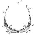
- FIG. 3is a perspective view of an exemplary earmuff
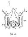
- FIG. 4is a perspective view of an exemplary respirator
- FIG. 5is a perspective view of an exemplary eyewear.
- Personal protective equipmentgenerally relies on the wearer establishing a proper fit to ensure the protection of the wearer. However, because not every person has the same dimensions, achieving a proper fit can be difficult. A means for demonstrating that a proper fit has been achieved can be determined by a change in appearance (e.g., color or design), at the point where the equipment interacts with the wearer.
- This personal protective equipmentcan include earplugs, ear muffs, respirators, eyewear, nose plugs, and the like. Additionally, the use of personal protective equipment that produces a change in appearance (e.g., color or design) can also be aesthetically pleasing promoting the use of the personal protective equipment.
- FIGS. 1 ( a ) and 2 ( a )in which an exemplary earplug construction according to a first embodiment of the present invention is illustrated and generally indicated at 10 .
- the earplug illustrated in FIGS. 1 ( a ) and 2 ( a )is a mushroom-shaped earplug
- other earplugsare contemplated, including cone-shaped, bullet-shaped, multi-flange-shaped, and the like, or any other earplugs which are, or which may become, known to those skilled in the art. Examples of suitable earplug types, shapes, and materials are described in U.S. Pat. Nos.
- the earplug 10comprises a stem 11 and body 12 .
- the earplug 10is generally mushroom-shaped and has an insertion end 14 and an opposing second end 16 .
- the diameter of the body 12 of the earplug 10is somewhat greater than that of the average adult human ear canal.
- the earplugs of the present inventionmay be formed from any number of suitable materials including foams and non-foams.
- the earplugcan be comprised of a material suitable for creating earplugs, including polyurethane, silicone, polyvinyl chloride foam, plasticized polymeric foams, temperature-dependent viscoelastic polymeric foams, dynamically stiff foams, rubber, polymer gels, thermoplastic elastomers, and combinations comprising at least one of the foregoing materials.
- included within or on the foregoing earplug materialis an energy-activated material present in an amount effective to exhibit a visual change, preferably a color change, upon exposure to an activation energy, preferably thermal energy, as illustrated sequentially in FIGS.
- the earplugwhen inserting the earplug 10 into a wearer's ears, the earplug interacts with the thermal energy in the interior of the ear canal and changes color (e.g., from vermillion to yellow) creating at least two visual zones.
- a first zone Z 1is the color of the earplug prior to insertion (e.g., vermillion) (see FIG. 1 ( a )) and a second visual zone Z 2 is the color of the earplug when it is exposed to and is absorbing thermal energy from the interior of the ear canal (e.g., yellow) (see FIG.
- FIG. 1 ( c )illustrates the change in color of at least a portion of the earplug 10 when exposed to the activation energy.
- This change in color(or activation of the energy activated material) preferably occurs when the temperature where the earplug is located is at about 50° F. to about 90° F., with about 70° F. to 80° F. preferred, and with about 75° F. (about 24° C.) especially preferred.
- the edge of the change in colorwill spread to at least a portion of the exterior portion of the earplug, or the entire earplug, enough to be visually apparent to an observer that a proper fit has been achieved for maximum attentuation.
- the color changecan also include the gradual change in intensity of the color (i.e., shading).
- a white earplugmay slowly change in appearance revealing a light red color when exposed to the activation energy prior to changing to a red color of higher intensity when it reaches the appropriate temperature.
- This change, when exposed to the activation energyis also illustrated sequentially in FIGS. 2 ( a ), 2 ( b ), and 2 ( c ) with the appearance of a design (or pattern or logo) 15 .
- This appearance of the design 15can also include the gradual change in the intensity of the appearance of the design 15 . (See FIG. 2 ( b ) and FIG. 2 ( c )).
- Another exampleincludes a change in appearance (e.g., color or design) when there is an absence or a presence of light.
- the energy-activated material of the earplug 10is a photochromic pigment.
- the earplug 10interacts with the lack of an activation energy (e.g., radiant energy or light) in the interior of the ear canal and changes color (e.g., from vermillion to yellow) creating at least two visual zones.
- an activation energye.g., radiant energy or light
- the first zone Z 1is the color (e.g., vermillion) of the earplug prior to insertion and the second visual zone Z 2 is the color (e.g., yellow) of the earplug when it is no longer exposed to an activation energy (e.g., radiant energy).
- an activation energye.g., radiant energy
- the edge of the change in colorwill spread to at least a portion of the exterior portion of the earplug, or the entire earplug, enough to be visually apparent to an observer that a proper fit has been achieved for maximum attentuation.
- the color changecan also include the gradual change in intensity of the color (i.e., shading). For example, a white earplug may slowly change in appearance revealing a light red color when exposed to the activation energy prior to changing to a red color of higher intensity.
- the appearance of the designcan also include the gradual change in the intensity of the appearance of the design when exposed to the activation energy.
- the change in appearancee.g., color, design, etc.
- an effective amount of energy-activated materialsuch as thermochromic and/or photochromic color pigment or dye
- thermochromic and photochromic pigmentsare available under the trade name of Chromicolor® and Photopia®, respectively, from Matsui Shikiso Chemical Co.
- the energy-activated materialcan be dispersed throughout the earplug material (e.g., foam or other appropriate earplug material) or provided as a coating (or layer) to the surface of the earplug. When disposing the energy activated material on the surface of the earplug, the energy-activated material can be patterned or evenly distributed.
- the amount of the energy-activated material utilizedshould be sufficient to produce the change in appearance (e.g., color or design) and is dependent upon whether the energy activated material is added prior to, or after, the forming the earplug.
- a symbol, or a patterni.e., a heart, a logo, etc.
- any amount of the color visible or a change in the color of the design or the appearance of a designcould indicate visually to an observer that a proper fit between the earplug 10 and the ear canal has been achieved. If the change is not visually apparent, the earplug 10 should be removed and re-fitted. This lack of color change also indicates that the wearer is only experiencing a low level of sound attenuation because the earplug 10 is not properly inserted into the ear. It is to be understood that the change in color is not limited to the use of vermillion and yellow, any number of color combinations may be used so long as the colors change in a manner which permits the observer to readily and easily know a proper fit is achieved between the earplug 10 and the ear canal.
- the use of change in appearancehelps to aid the wearer in obtaining a better fit for the earplug 10 .
- the wearermay view the depth of insertion of the earplug 10 into the wearer's ear by using appropriate devices, e.g., a mirror. By observing the appearance change that is visible, the wearer can immediately ascertain the degree of the fit and the corresponding level of sound attenuation being offered by the earplug 10 . Adjustments may then be made, if needed, so that the earplug 10 is properly being worn.
- the change in color, or appearance of a design, symbol or patterncan indicate a proper fit, the reversible change is also aesthetically pleasing. Accordingly, a variety of colors, designs, or logos can be utilized on the earplug 10 for aesthetic reasons in an effort to promote use of the earplug.
- the earmuff 20is comprised of a connecting member and a pair of muffs suitable for covering the wearer's ears.
- the muffsare suspended from opposite portions of the connecting member.
- the connecting member illustrated in FIG. 3is a headband 22
- other membersare contemplated, including a helmet with auxiliary hardware or any other means which are, or which may become, known to those skilled in the art. Examples of suitable ear muff types, shapes, and materials are described in U.S. Pat. Nos. 4,459,707, 5,924,138, 5,970,160, 5,979,451, 6,148,446, all of the contents of which are incorporated herein by reference.
- the earmuff 20comprises a headband 22 and muffs 24 , 25 .
- Muffs 24 , 25are comprised of cups 26 , 27 and ear seal cushions 28 , 29 .
- the cups 26 , 27 and/or the ear seal cushions 28 , 29can be at least partially or entirely porous.
- the ear seal cushions 28 , 29can be comprised of a material including polyurethane, silicone, polyvinyl chloride foam, plasticized polymeric foams, temperature-dependent viscoelastic polymeric foams, dynamically stiff foams, rubber, polymer gels, thermoplastic elastomers, and the like, and combinations comprising at least one of the foregoing materials.
- the ear seal cushions 28 , 29can be coated with a nonporous material such as vinyl, polyurethane, silicone, and the like, as well as combinations comprising at least one of the foregoing materials.
- the material of the ear seal cushions 28 , 29 or the material chosen to coat the ear seal cushions 28 , 29can be combined with the energy-activated material described above (e.g., thermochromic pigments, photochromic pigments, etc.).
- the energy-activated materialcan be dispersed throughout the ear cushion foam (or other appropriate ear cushion material) or provided as a coating (or layer) to the surface of the ear cushion.
- the energy-activated materialcan be patterned or evenly distributed.
- the amount of the energy-activated material utilizedshould be sufficient to produce the change in apperance (e.g., color or design) and is dependent upon whether the energy-activated material is added prior to, or after, the forming the ear cushion.
- any amount of the appearance changee.g., color or design
- any amount of the appearance changevisually apparent to an observer can indicate that a proper fit is achieved. If an appearance change does not appear in the proper places, then there is a poor fit and consequently, the earmuff 20 should be removed and re-fitted. This also indicates that the wearer is only experiencing a low level of sound attenuation because the earmuff 20 is not properly inserted onto the ear. Accordingly, the appearance change (e.g., color or design) is visually apparent and permits a safety officer, the wearer, or other individual to ascertain whether the wearer is complying with existing safety rules and regulations.
- the appearance changee.g., color or design
- the change in appearancee.g., color or design
- the reversible changeis also aesthetically pleasing and so can promote use of the earmuff.
- a variety of colors, designs, or logoscan be utilized on the earmuffs 20 .
- FIG. 4an exemplary respirator construction according to a third embodiment of the present invention is illustrated and generally indicated at 30 .
- a half-mask respiratoris illustrated, use with a full-face respirator, a face mask, and the like is also contemplated, or any other means which are, or which may become, known to those skilled in the art.
- suitable respirator types, shapes, and materialsare described in U.S. Pat. Nos. 4,454,881, 4,592,350, 4,600,002, 5,924,420, 6,116,236, all of the contents of which are incorporated herein by reference.
- the respirator 30comprises a mask 31 with inclined side walls 32 which flare from an apex and is intended to fit over the bridge of the nose of the user to flattened side surfaces.
- the mask 31has an in-turned flexible sealing lip or flange having a radius, which extends around the entire edge that is intended to come into contact with the face of the user. This flange is contoured generally to conform to and form a leak-free seal with the user's face.
- Chemical cartridges 33are shown as being attached to the upstream side of inhalation valve housings (or fittings) 37 in which are mounted flexible disk-type inhalation valves (not shown).
- An exhalation fitting 36having an exhalation valve, is located at the base of the mask 31 .
- the halter (or yoke) 35is formed of a material having sufficient flexibility and resilience to readily conform to the contour of the mask 31 is provided with structural ring portions that fit around the inhalation valve housings 37 in the side wall portions in the mask 31 .
- the yoke 35also has fastening means for the attachment of suspension straps 34 to connect the mask 31 to a headpiece (not shown).
- the material of the mask 31has sufficient inherent flexibility and its thickness is selected so that it readily conforms to the facial structure of a wide range of potential users.
- Suitable mask 31 materialsinclude polyurethane, silicone, polyvinyl chloride foam, plasticized polymeric foams, temperature-dependent viscoelastic polymeric foams, dynamically stiff foams, rubber, polymer gels, thermoplastic elastomers, and the like, as well as combinations comprising at least one of the foregoing materials.
- the material of the mask 31can be combined with the energy-activated material described above (e.g., thermochromic pigments, photochromic pigments, etc.).
- the energy-activated materialcan be dispersed throughout the rubber (or other appropriate mask material) or provided as a coating (or layer) to the surface of the mask.
- the energy-activated materialcan be patterned or evenly distributed. The amount of the energy-activated material utilized should be sufficient to produce the change in appearance (e.g., color or design) and is dependent upon whether the energy-activated material is added prior to, or after, the forming the mask.
- respiratorAn example of using the respirator is as follows. A wearer typically puts on (dons) a respirator by clipping the lower straps behind the neck and then lifting the headpiece (or cradle) up onto the top of the crown while simultaneously guiding the face mask and yoke portion into position on the face. The straps are then manipulated and adjusted until a good fit is achieved and a successful face seal check is performed. Removal, or doffing, of the respirator is performed opposite the donning operation wherein the lower straps are unbuckled and the cradle is removed from the head while the face mask is withdrawn from the face of the wearer. In the course of an average day a worker required to wear a respirator may don and doff the respirator up to 20 times.
- the appearance change(e.g., color or design) is visually apparent to permit a safety officer, the wearer, or other individual to ascertain whether the wearer is complying with existing safety rules and regulations. For example, when the wearer fits the respirator 30 to his/her face any amount of the appearnce change (e.g., color or design) visually apparent to an observer will indicate that a proper fit is achieved. If a appearance change does not appear in the proper places, then there is a poor fit and consequently, the respirator 30 should be removed and re-fitted. This also indicates that the wearer is not protected against breathing in potentially harmful contaminants since the respirator 30 is not properly fitted to the face.
- the appearnce changee.g., color or design
- the change in appearancee.g., color or design
- the reversible changeis also aesthetically pleasing and so can promote use of the respirator.
- a variety of colors, designs, or logoscan be utilized on the respirator 30 .
- an exemplary pair of eyewear according to another embodiment of the present inventionis illustrated and generally indicated at 40 .
- plano eyewear for use in safety and recreational (i.e., sports) applicationsis contemplated (although this invention would be equally suitable for eyewear incorporating prescription lenses).
- suitable eyewear applicationsinclude spectacles, goggles, face shields, respirator lenses, visors, helmets and the like.
- suitable eyewear types, shapes, and materialsare described in U.S. Pat. Nos. 5,138,723, 5,345,616, 5,617,588, 5,983,390, all of the contents of which are incorporated herein by reference.
- a pair of safety gogglesare illustrated, the invention is not limited and includes all eyewear utilized as protective equipment or any other eyewear which are, or which may become, known to those skilled in the art.
- the eyewear 40comprises lenses 42 which are connected to rims 44 .
- Temple bodies 46attach to the rims 44 at attachment points 48 .
- Disposed along the rim towards the interior of the eyewear 40is a cushion material 50 .
- the cushion material 50provides for a seal against the wearer's face to prevent the splashing or intrusion of contaminants into the wearer's eyes.
- the material of the cushion 50has sufficient inherent flexibility and its thickness is selected so that it readily conforms to the facial structure of a wide range of potential users.
- Suitable materials for the cushion 50include polyurethane, silicone, polyvinyl chloride foam, plasticized polymeric foams, temperature-dependent viscoelastic polymeric foams, dynamically stiff foams, rubber, polymer gels, thermoplastic elastomers, and the like, as well as combinations comprising at least one of the foregoing materials.
- the material of the cushion 50can be combined with the energy-activated material described above (e.g., thermochromic pigments, photochromic pigments, etc.).
- the energy-activated materialcan be dispersed throughout the cushion 50 material (e.g., foam or other appropriate cushion material) or provided as a coating (or layer) to the surface of the cushion 50 .
- the energy-activated materialcan be patterned or evenly distributed. The amount of the energy-activated material utilized should be sufficient to produce the change in appearance (e.g., color or design) and is dependent upon whether the energy-activated material is added prior to, or after, the forming the cushion 50 .
- the appearance change(e.g., color or design) is visually apparent to permit a safety officer, the wearer, or other individual to ascertain whether the wearer is complying with existing safety rules and regulations.
- An example of using the eyewear 40is as follows. When the wearer fits the eyewear 40 to his/her face any amount of the appearance change (e.g., color or design) visually apparent to an observer will indicate that a proper fit is achieved. If an appearance change does not appear in the proper places, then there is a poor fit and consequently, the eyewear 40 should be removed and re-fitted. This also indicates that the wearer is not protected against splashing of contaminants because the eyewear 40 is not properly fitted to the face.
- the personal safety protective products having an energy activated materialis not limited to the color configurations or designs recited hereinbefore and any number of color schemes and designs may be used so long as the visual zones are visually distinct from each other.
- the visual zonesinclude the color zone when not exposed to the temperatures of the human body (i.e., vermillion) and the color zone exposed to the temperature of the human body (i.e., yellow). Accordingly, the visual zones permit an observer or the wearer to immediately ascertain the degree of fit by simply viewing which visual zone(s) is visible. This permits a safety officer or other individual, including the wearer, to easily determine whether the wearer is complying with existing safety rules and regulations.
- colorsis not limited to the use of vermillion or yellow and a number of color combinations may be used so long as the colors mark or indicate the change in temperature, which permit the observer to readily and easily know the type of fit.
- the wearermay view the proper fit of the protective equipment by using appropriate devices, e.g., a mirror. By observing the visible change of color, the wearer can immediately ascertain the degree of the fit and the corresponding level of protection being offered by the device. Adjustments may then be made, if needed, so that the device is properly being worn.
- the personal safety protective products with proper fit characteristicsprovides an effective visual aid in determining whether the wearer is complying with existing safety rules, regulations, and the like and also provides a visual aid to permit the wearer to obtain a better fit.
- a visual aidto permit the wearer to obtain a better fit.
- thispermits the wearer to be easily instructed as to the proper fit that is required in any given environment by simply referencing the visual zones of the device and indicating which visual zones may or may not be visible during use of the device.
- the multicolored device or device with logos, patterns or symbolsare visually pleasing and appealing; and as a result, the incorporation of this invention in personal protective equipment may aid in user acceptance in the workplace.
Landscapes
- Health & Medical Sciences (AREA)
- Life Sciences & Earth Sciences (AREA)
- General Health & Medical Sciences (AREA)
- Veterinary Medicine (AREA)
- Public Health (AREA)
- Animal Behavior & Ethology (AREA)
- Engineering & Computer Science (AREA)
- Biomedical Technology (AREA)
- Heart & Thoracic Surgery (AREA)
- Vascular Medicine (AREA)
- Acoustics & Sound (AREA)
- Physics & Mathematics (AREA)
- Biophysics (AREA)
- Otolaryngology (AREA)
- Psychology (AREA)
- Ophthalmology & Optometry (AREA)
- Emergency Management (AREA)
- Business, Economics & Management (AREA)
- Pulmonology (AREA)
- Respiratory Apparatuses And Protective Means (AREA)
Abstract
Description
Claims (37)
Priority Applications (3)
| Application Number | Priority Date | Filing Date | Title |
|---|---|---|---|
| US09/841,479US6622816B2 (en) | 2001-04-24 | 2001-04-24 | Personal protective devices having an energy activated material |
| PCT/US2002/011680WO2002085267A1 (en) | 2001-04-24 | 2002-04-11 | Personal protective devices having an energy activated material |
| EP02739145AEP1383451A1 (en) | 2001-04-24 | 2002-04-11 | Personal protective devices having an energy activated material |
Applications Claiming Priority (1)
| Application Number | Priority Date | Filing Date | Title |
|---|---|---|---|
| US09/841,479US6622816B2 (en) | 2001-04-24 | 2001-04-24 | Personal protective devices having an energy activated material |
Publications (2)
| Publication Number | Publication Date |
|---|---|
| US20020153192A1 US20020153192A1 (en) | 2002-10-24 |
| US6622816B2true US6622816B2 (en) | 2003-09-23 |
Family
ID=25284980
Family Applications (1)
| Application Number | Title | Priority Date | Filing Date |
|---|---|---|---|
| US09/841,479Expired - Fee RelatedUS6622816B2 (en) | 2001-04-24 | 2001-04-24 | Personal protective devices having an energy activated material |
Country Status (3)
| Country | Link |
|---|---|
| US (1) | US6622816B2 (en) |
| EP (1) | EP1383451A1 (en) |
| WO (1) | WO2002085267A1 (en) |
Cited By (5)
| Publication number | Priority date | Publication date | Assignee | Title |
|---|---|---|---|---|
| US20040194195A1 (en)* | 2003-04-01 | 2004-10-07 | Palmer Stephen L. | Chemiluminescently illuminated costume safety mask |
| WO2007098540A1 (en)* | 2006-03-01 | 2007-09-07 | Resmed Ltd | Method and apparatus for reminding user to replace and/or service cpap apparatus and/or component thereof |
| US20090120432A1 (en)* | 2007-11-09 | 2009-05-14 | Macdonald John Gavin | Moisture indicator for heat and moisture exchange devices |
| US9138189B1 (en) | 2012-04-02 | 2015-09-22 | Marisela Payne | Earplug with thermochromic probe and stem for indicating unsafe core body temperature |
| US9507175B2 (en) | 2012-10-16 | 2016-11-29 | 3M Innovative Properties Company | Methods and devices for evaluating eyewear fit |
Families Citing this family (7)
| Publication number | Priority date | Publication date | Assignee | Title |
|---|---|---|---|---|
| US7523750B2 (en)* | 2003-11-12 | 2009-04-28 | Krzysztofik J Mario | Breathing respirator |
| US8221861B2 (en)* | 2007-05-04 | 2012-07-17 | Personics Holdings Inc. | Earguard sealing system II: single-chamber systems |
| US7984716B2 (en)* | 2007-06-22 | 2011-07-26 | Kimberly-Clark Worldwide Inc. | Self-conforming sound attenuation earplug |
| US8113207B2 (en) | 2008-08-22 | 2012-02-14 | Kimberly-Clark Worldwide, Inc. | Self-conforming sound attenuation earplug |
| WO2014019626A1 (en)* | 2012-08-02 | 2014-02-06 | Phonak Ag | Diagnostic coating |
| CN105380317A (en)* | 2015-12-21 | 2016-03-09 | 华北理工大学 | Disposable medical mask with body temperature indicator strip |
| TWI632357B (en)* | 2017-05-03 | 2018-08-11 | 熱映光電股份有限公司 | Probe cover dispenser device |
Citations (14)
| Publication number | Priority date | Publication date | Assignee | Title |
|---|---|---|---|---|
| US4488547A (en) | 1982-09-07 | 1984-12-18 | Kenneth R. Bowers, Jr. | Face mask |
| US4567122A (en)* | 1982-01-15 | 1986-01-28 | The Secretary Of State For Defence In Her Britannic Majesty's Government Of The United Kingdom Of Great Britain And Northern Ireland | Phototropic materials |
| US4681791A (en)* | 1985-01-30 | 1987-07-21 | Pilot Ink Co., Ltd. | Thermochromic textile material |
| US5333622A (en) | 1990-08-20 | 1994-08-02 | The Center For Innovative Technology | Earplug and hearing devices formed in-situ |
| US5480482A (en) | 1991-11-04 | 1996-01-02 | The United States Of America As Represented By The Secretary Of The Navy | Reversible thermochromic pigments |
| US5517700A (en) | 1993-09-08 | 1996-05-21 | Sports-Mitt International | Goggle and desiccant assembly |
| US5591255A (en) | 1993-12-29 | 1997-01-07 | Chromatic Technologies, Inc. | Thermochromic ink formulations, nail lacquer and methods of use |
| US5617849A (en)* | 1995-09-12 | 1997-04-08 | Minnesota Mining And Manufacturing Company | Respirator having thermochromic fit-indicating seal |
| GB2306346A (en) | 1995-10-27 | 1997-05-07 | Titus Int Plc | Filtering apparatus for use in respirators |
| US5811742A (en) | 1997-04-21 | 1998-09-22 | Howard S. Leight And Associates, Inc. | Dual earplug |
| US5997849A (en) | 1993-12-29 | 1999-12-07 | Chromatic Technologies, Inc. | Thermochromic ink formulations, nail lacquer and methods of use |
| US6105715A (en) | 1999-11-05 | 2000-08-22 | Aearo Company | Multi-color variably attenuating earplug |
| US6328446B1 (en)* | 1995-03-03 | 2001-12-11 | Vision-Ease Lens, Inc. | Production of optical elements |
| US20020136899A1 (en)* | 2001-03-21 | 2002-09-26 | Derojas Agustin Alberto | Lens with photochromic elastomer film and method of making it |
Family Cites Families (7)
| Publication number | Priority date | Publication date | Assignee | Title |
|---|---|---|---|---|
| US4193396A (en) | 1978-04-28 | 1980-03-18 | E-A-R Corporation | Paired earplug construction |
| US4461290A (en) | 1980-09-08 | 1984-07-24 | Cabot Corporation | Hearing protectors |
| US4936411A (en) | 1988-08-19 | 1990-06-26 | Cabot Corporation | Detectable earplug |
| US5188123A (en) | 1990-08-20 | 1993-02-23 | Cabot Safety Corporation | Hearing protective earplug having alternative modes of insertion |
| US5203352A (en) | 1990-10-16 | 1993-04-20 | Cabot Safety Corporation | Polymeric foam earplug |
| US5792998A (en) | 1993-04-19 | 1998-08-11 | Cabot Safety Intermediate Corporation | Acoustical hearing protective devices utilizing dynamically stiff foam and methods of producing same |
| US5799658A (en) | 1996-08-15 | 1998-09-01 | Cabot Safety Intermediate Corporation | Hearing protective device comprising a foam and a porous component and method of manufacture thereof |
- 2001
- 2001-04-24USUS09/841,479patent/US6622816B2/ennot_activeExpired - Fee Related
- 2002
- 2002-04-11EPEP02739145Apatent/EP1383451A1/ennot_activeWithdrawn
- 2002-04-11WOPCT/US2002/011680patent/WO2002085267A1/ennot_activeApplication Discontinuation
Patent Citations (14)
| Publication number | Priority date | Publication date | Assignee | Title |
|---|---|---|---|---|
| US4567122A (en)* | 1982-01-15 | 1986-01-28 | The Secretary Of State For Defence In Her Britannic Majesty's Government Of The United Kingdom Of Great Britain And Northern Ireland | Phototropic materials |
| US4488547A (en) | 1982-09-07 | 1984-12-18 | Kenneth R. Bowers, Jr. | Face mask |
| US4681791A (en)* | 1985-01-30 | 1987-07-21 | Pilot Ink Co., Ltd. | Thermochromic textile material |
| US5333622A (en) | 1990-08-20 | 1994-08-02 | The Center For Innovative Technology | Earplug and hearing devices formed in-situ |
| US5480482A (en) | 1991-11-04 | 1996-01-02 | The United States Of America As Represented By The Secretary Of The Navy | Reversible thermochromic pigments |
| US5517700A (en) | 1993-09-08 | 1996-05-21 | Sports-Mitt International | Goggle and desiccant assembly |
| US5591255A (en) | 1993-12-29 | 1997-01-07 | Chromatic Technologies, Inc. | Thermochromic ink formulations, nail lacquer and methods of use |
| US5997849A (en) | 1993-12-29 | 1999-12-07 | Chromatic Technologies, Inc. | Thermochromic ink formulations, nail lacquer and methods of use |
| US6328446B1 (en)* | 1995-03-03 | 2001-12-11 | Vision-Ease Lens, Inc. | Production of optical elements |
| US5617849A (en)* | 1995-09-12 | 1997-04-08 | Minnesota Mining And Manufacturing Company | Respirator having thermochromic fit-indicating seal |
| GB2306346A (en) | 1995-10-27 | 1997-05-07 | Titus Int Plc | Filtering apparatus for use in respirators |
| US5811742A (en) | 1997-04-21 | 1998-09-22 | Howard S. Leight And Associates, Inc. | Dual earplug |
| US6105715A (en) | 1999-11-05 | 2000-08-22 | Aearo Company | Multi-color variably attenuating earplug |
| US20020136899A1 (en)* | 2001-03-21 | 2002-09-26 | Derojas Agustin Alberto | Lens with photochromic elastomer film and method of making it |
Non-Patent Citations (9)
| Title |
|---|
| "International Search Report", PCT/US02/11680, Aug. 5, 2002. |
| C.T.I. 4320 Northpark Drive Suite B Colorado Spring, CO 80907-4247 USA.** |
| Color Option 1997, 1998, 1999, 2000 Chromatic Technologies, Inc.** |
| CTI Chromatic Technologies, Incorpated Dynacolor Data Sheet Thermochromic Water-Based Flexographic Ink.** |
| Journal of Chemical Education 1999 Division of Chemical Education, Inc. American Chemcal Society.** |
| Madsci Network: Chemistry Copyright 1996 Washington,.** |
| Substrates 1997, 1998, 1999, 2000, Chromatic Technologies, Inc.** |
| Thermochromic Colorant Serials.** |
| Water-Based Flexo Data.** |
Cited By (7)
| Publication number | Priority date | Publication date | Assignee | Title |
|---|---|---|---|---|
| US20040194195A1 (en)* | 2003-04-01 | 2004-10-07 | Palmer Stephen L. | Chemiluminescently illuminated costume safety mask |
| US6832392B2 (en)* | 2003-04-01 | 2004-12-21 | Omniglow Corporation | Chemiluminescently illuminated costume safety mask |
| WO2007098540A1 (en)* | 2006-03-01 | 2007-09-07 | Resmed Ltd | Method and apparatus for reminding user to replace and/or service cpap apparatus and/or component thereof |
| US20090120432A1 (en)* | 2007-11-09 | 2009-05-14 | Macdonald John Gavin | Moisture indicator for heat and moisture exchange devices |
| US7913640B2 (en)* | 2007-11-09 | 2011-03-29 | Kimberly-Clark Worldwide, Inc. | Moisture indicator for heat and moisture exchange devices |
| US9138189B1 (en) | 2012-04-02 | 2015-09-22 | Marisela Payne | Earplug with thermochromic probe and stem for indicating unsafe core body temperature |
| US9507175B2 (en) | 2012-10-16 | 2016-11-29 | 3M Innovative Properties Company | Methods and devices for evaluating eyewear fit |
Also Published As
| Publication number | Publication date |
|---|---|
| US20020153192A1 (en) | 2002-10-24 |
| EP1383451A1 (en) | 2004-01-28 |
| WO2002085267A1 (en) | 2002-10-31 |
Similar Documents
| Publication | Publication Date | Title |
|---|---|---|
| CA2389967C (en) | Multi-color variably attenuating earplug | |
| US6622816B2 (en) | Personal protective devices having an energy activated material | |
| US7020901B2 (en) | Eye and ear protection apparatus | |
| BR0105933A (en) | Protective glasses with adjustable lanyard | |
| US6666554B2 (en) | Protective eyewear kit | |
| KR101810603B1 (en) | Goggle mask | |
| US20190008228A1 (en) | Integrated non-conflicting headgear platform system and method | |
| RU2640984C2 (en) | Respiratory mask with nose support element-expander | |
| KR200495244Y1 (en) | UV protection patch having earring parts | |
| US6990981B2 (en) | Protective eyewear for healthcare providers | |
| US5924138A (en) | Apparatus and methods for aural protection | |
| US6976275B1 (en) | Protective ear shield | |
| JPS62221373A (en) | Pollen protector | |
| CA2346047C (en) | Spectacle kit | |
| Bartkowiak et al. | Use of personal protective equipment | |
| US6481846B1 (en) | Ear and eye protection apparatus | |
| US20030172444A1 (en) | Eye protection | |
| KR20160000517U (en) | Mask For Protecting Body | |
| US5890236A (en) | Firefighter goggles | |
| US20190314203A1 (en) | Protective equipment | |
| US20230233886A1 (en) | Respirator | |
| US6231178B1 (en) | Protective sunglasses system having removable prescription capable lenses | |
| KR20210128717A (en) | Industrial Neck Warmer | |
| KR101482881B1 (en) | Sun cap | |
| KR102094339B1 (en) | Fine dust protection glasses |
Legal Events
| Date | Code | Title | Description |
|---|---|---|---|
| AS | Assignment | Owner name:BANKERS TRUST COMPANY, NEW YORK Free format text:SECURITY INTEREST;ASSIGNOR:CABOT SAFETY INTERMEDIATE CORPORATION;REEL/FRAME:012075/0227 Effective date:20010713 | |
| AS | Assignment | Owner name:CABOT SAFETY INTERMEDIATE CORP, MASSACHUSETTS Free format text:ASSIGNMENT OF ASSIGNORS INTEREST;ASSIGNORS:FALCO, ROBERT N.;KLADDEN, CYNTHIA A.;REEL/FRAME:012640/0886 Effective date:20010815 | |
| AS | Assignment | Owner name:DEUTSCHE BANK AG, NEW YORK BRANCH, NEW YORK Free format text:SECURITY AGREEMENT;ASSIGNOR:CABOT SAFETY INTERMEDIATE CORPORATION;REEL/FRAME:015293/0386 Effective date:20040420 Owner name:CABOT SAFETY INTERMEDIATE CORPORATION, DELAWARE Free format text:PATENT RELEASE;ASSIGNOR:DEUTSCHE BANK TRUST COMPANY AMERICAS;REEL/FRAME:015302/0494 Effective date:20040420 Owner name:DEUTSCHE BANK AG, NEW YORK BRANCH,NEW YORK Free format text:SECURITY AGREEMENT;ASSIGNOR:CABOT SAFETY INTERMEDIATE CORPORATION;REEL/FRAME:015293/0386 Effective date:20040420 | |
| AS | Assignment | Owner name:CABOT SAFETY INTERMEDIATE CORPORATION,NORTH CAROLI Free format text:RELEASE OF SECURITY INTEREST;ASSIGNOR:DEUTSCHE BANK AG, NEW YORK BRANCH;REEL/FRAME:017626/0347 Effective date:20060324 Owner name:CABOT SAFETY INTERMEDIATE CORPORATION, NORTH CAROL Free format text:RELEASE OF SECURITY INTEREST;ASSIGNOR:DEUTSCHE BANK AG, NEW YORK BRANCH;REEL/FRAME:017626/0347 Effective date:20060324 | |
| AS | Assignment | Owner name:BANK OF AMERICA, N.A., AS SECOND LIEN COLLATERAL A Free format text:SECURITY AGREEMENT;ASSIGNOR:CABOT SAFETY INTERMEDIATE CORPORATION;REEL/FRAME:017435/0764 Effective date:20060324 Owner name:BANK OF AMERICA, N.A., AS FIRST LIEN COLLATERAL AG Free format text:SECURITY AGREEMENT;ASSIGNOR:CABOT SAFETY INTERMEDIATE CORPORATION;REEL/FRAME:017435/0721 Effective date:20060324 | |
| AS | Assignment | Owner name:CABOT SAFETY INTERMEDIATE CORPORATION,NORTH CAROLI Free format text:RELEASE OF SECURITY INTEREST;ASSIGNOR:DEUTSCHE BANK AG, NEW YORK BRANCH;REEL/FRAME:017663/0508 Effective date:20060324 Owner name:CABOT SAFETY INTERMEDIATE CORPORATION, NORTH CAROL Free format text:RELEASE OF SECURITY INTEREST;ASSIGNOR:DEUTSCHE BANK AG, NEW YORK BRANCH;REEL/FRAME:017663/0508 Effective date:20060324 | |
| FPAY | Fee payment | Year of fee payment:4 | |
| AS | Assignment | Owner name:CABOT SAFETY INTERMEDIATE CORPORATION, DELAWARE Free format text:RELEASE OF FIRST LIEN SECURITY INTEREST AT REEL/FRAME NO. 17435/0721;ASSIGNOR:BANK OF AMERICA, N.A., AS FIRST LIEN COLLATERAL AGENT;REEL/FRAME:019511/0914 Effective date:20070601 Owner name:BANK OF AMERICA, N.A., AS FIRST LIEN COLLATERAL AG Free format text:GRANT OF FIRST LIEN SECURITY INTEREST IN UNITED STATES PATENTS AND TRADEMARKS;ASSIGNOR:CABOT SAFETY INTERMEDIATE CORPORATION;REEL/FRAME:019520/0001 Effective date:20070601 Owner name:CABOT SAFETY INTERMEDIATE CORPORATION,DELAWARE Free format text:RELEASE OF FIRST LIEN SECURITY INTEREST AT REEL/FRAME NO. 17435/0721;ASSIGNOR:BANK OF AMERICA, N.A., AS FIRST LIEN COLLATERAL AGENT;REEL/FRAME:019511/0914 Effective date:20070601 | |
| CC | Certificate of correction | ||
| AS | Assignment | Owner name:CABOT SAFETY INTERMEDIATE CORPORATION, DELAWARE Free format text:RELEASE OF FIRST LIEN SECURITY INTEREST AT REEL/FRAME NO. 19520/0001;ASSIGNOR:BANK OF AMERICA, N.A.;REEL/FRAME:020733/0440 Effective date:20080401 Owner name:CABOT SAFETY INTERMEDIATE CORPORATION, DELAWARE Free format text:RELEASE OF SECOND LIEN SECURITY INTEREST AT REEL/FRAME NO. 17435/0764;ASSIGNOR:BANK OF AMERICA, N.A.;REEL/FRAME:020733/0510 Effective date:20080401 Owner name:CABOT SAFETY INTERMEDIATE CORPORATION,DELAWARE Free format text:RELEASE OF SECOND LIEN SECURITY INTEREST AT REEL/FRAME NO. 17435/0764;ASSIGNOR:BANK OF AMERICA, N.A.;REEL/FRAME:020733/0510 Effective date:20080401 Owner name:CABOT SAFETY INTERMEDIATE CORPORATION,DELAWARE Free format text:RELEASE OF FIRST LIEN SECURITY INTEREST AT REEL/FRAME NO. 19520/0001;ASSIGNOR:BANK OF AMERICA, N.A.;REEL/FRAME:020733/0440 Effective date:20080401 | |
| AS | Assignment | Owner name:CABOT SAFETY INTERMEDIATE, LLC, DELAWARE Free format text:CHANGE OF NAME;ASSIGNOR:CABOT SAFETY INTERMEDIATE CORPORATION;REEL/FRAME:021976/0834 Effective date:20080926 | |
| AS | Assignment | Owner name:3M INNOVATIVE PROPERTIES COMPANY, MINNESOTA Free format text:ASSIGNMENT OF ASSIGNORS INTEREST;ASSIGNOR:CABOT SAFETY INTERMEDIATE LLC;REEL/FRAME:022052/0076 Effective date:20081208 | |
| FPAY | Fee payment | Year of fee payment:8 | |
| REMI | Maintenance fee reminder mailed | ||
| LAPS | Lapse for failure to pay maintenance fees | ||
| STCH | Information on status: patent discontinuation | Free format text:PATENT EXPIRED DUE TO NONPAYMENT OF MAINTENANCE FEES UNDER 37 CFR 1.362 | |
| FP | Lapsed due to failure to pay maintenance fee | Effective date:20150923 |