US6622786B1 - Heat sink structure with pyramidic and base-plate cut-outs - Google Patents
Heat sink structure with pyramidic and base-plate cut-outsDownload PDFInfo
- Publication number
- US6622786B1 US6622786B1US10/125,302US12530202AUS6622786B1US 6622786 B1US6622786 B1US 6622786B1US 12530202 AUS12530202 AUS 12530202AUS 6622786 B1US6622786 B1US 6622786B1
- Authority
- US
- United States
- Prior art keywords
- heat sink
- layer
- layers
- heat
- base plate
- Prior art date
- Legal status (The legal status is an assumption and is not a legal conclusion. Google has not performed a legal analysis and makes no representation as to the accuracy of the status listed.)
- Expired - Fee Related
Links
- 238000001816coolingMethods0.000claimsabstractdescription22
- 239000000463materialSubstances0.000claimsdescription17
- 238000000034methodMethods0.000claimsdescription11
- 230000000930thermomechanical effectEffects0.000claimsdescription5
- 229910052782aluminiumInorganic materials0.000claimsdescription3
- XAGFODPZIPBFFR-UHFFFAOYSA-NaluminiumChemical group[Al]XAGFODPZIPBFFR-UHFFFAOYSA-N0.000claimsdescription3
- 239000002131composite materialSubstances0.000claimsdescription2
- 230000001174ascending effectEffects0.000abstractdescription2
- 230000003467diminishing effectEffects0.000abstract1
- 239000010410layerSubstances0.000description66
- 230000008901benefitEffects0.000description4
- 238000004519manufacturing processMethods0.000description4
- XUIMIQQOPSSXEZ-UHFFFAOYSA-NSiliconChemical compound[Si]XUIMIQQOPSSXEZ-UHFFFAOYSA-N0.000description3
- 229910052710siliconInorganic materials0.000description3
- 239000010703siliconSubstances0.000description3
- 229910000679solderInorganic materials0.000description3
- 238000005266castingMethods0.000description2
- 230000000694effectsEffects0.000description2
- 238000001125extrusionMethods0.000description2
- 230000017525heat dissipationEffects0.000description2
- 230000020169heat generationEffects0.000description2
- 230000008569processEffects0.000description2
- 238000005086pumpingMethods0.000description2
- RYGMFSIKBFXOCR-UHFFFAOYSA-NCopperChemical compound[Cu]RYGMFSIKBFXOCR-UHFFFAOYSA-N0.000description1
- 239000004593EpoxySubstances0.000description1
- 229910045601alloyInorganic materials0.000description1
- 239000000956alloySubstances0.000description1
- 238000005219brazingMethods0.000description1
- 229910052802copperInorganic materials0.000description1
- 239000010949copperSubstances0.000description1
- 230000001351cycling effectEffects0.000description1
- 230000007423decreaseEffects0.000description1
- 238000004100electronic packagingMethods0.000description1
- 230000001788irregularEffects0.000description1
- 230000013011matingEffects0.000description1
- 230000007246mechanismEffects0.000description1
- 229910052751metalInorganic materials0.000description1
- 239000002184metalSubstances0.000description1
- 238000012986modificationMethods0.000description1
- 230000004048modificationEffects0.000description1
- 238000004806packaging method and processMethods0.000description1
- 239000004065semiconductorSubstances0.000description1
- HBMJWWWQQXIZIP-UHFFFAOYSA-Nsilicon carbideChemical compound[Si+]#[C-]HBMJWWWQQXIZIP-UHFFFAOYSA-N0.000description1
- 229910010271silicon carbideInorganic materials0.000description1
- 239000002356single layerSubstances0.000description1
- 239000013585weight reducing agentSubstances0.000description1
Images


Classifications
- F—MECHANICAL ENGINEERING; LIGHTING; HEATING; WEAPONS; BLASTING
- F28—HEAT EXCHANGE IN GENERAL
- F28F—DETAILS OF HEAT-EXCHANGE AND HEAT-TRANSFER APPARATUS, OF GENERAL APPLICATION
- F28F3/00—Plate-like or laminated elements; Assemblies of plate-like or laminated elements
- F28F3/02—Elements or assemblies thereof with means for increasing heat-transfer area, e.g. with fins, with recesses, with corrugations
- F28F3/022—Elements or assemblies thereof with means for increasing heat-transfer area, e.g. with fins, with recesses, with corrugations the means being wires or pins
- H—ELECTRICITY
- H01—ELECTRIC ELEMENTS
- H01L—SEMICONDUCTOR DEVICES NOT COVERED BY CLASS H10
- H01L23/00—Details of semiconductor or other solid state devices
- H01L23/34—Arrangements for cooling, heating, ventilating or temperature compensation ; Temperature sensing arrangements
- H01L23/36—Selection of materials, or shaping, to facilitate cooling or heating, e.g. heatsinks
- H01L23/367—Cooling facilitated by shape of device
- H01L23/3677—Wire-like or pin-like cooling fins or heat sinks
- H—ELECTRICITY
- H01—ELECTRIC ELEMENTS
- H01L—SEMICONDUCTOR DEVICES NOT COVERED BY CLASS H10
- H01L2924/00—Indexing scheme for arrangements or methods for connecting or disconnecting semiconductor or solid-state bodies as covered by H01L24/00
- H01L2924/0001—Technical content checked by a classifier
- H01L2924/0002—Not covered by any one of groups H01L24/00, H01L24/00 and H01L2224/00
Definitions
- the present inventionrelates to heat sink structures and, more articularly, to stacked heat sink structures with central openings and methods for making same.
- the electronics industryis continuously endeavoring to reduce both the size of electronic packages and the pitch between conductive I/O contacts in order to accommodate the higher counts coming from higher density chips.
- increased speed and miniaturizationcomes increased heat generation and its attendant problems, such as, increased failure rate of solder joints during temperature cycling due to the higher strain levels at the joints.
- heat dissipating meansTo reduce the levels of heat generated within electronic packages and, thus solder joint fatigue for example, various forms of heat dissipating means have been employed.
- One mechanism employed to facilitate heat dissipationis a heat sink positioned in thermal contact with the electronic package.
- the heat sinkis either clamped or bonded to the semiconductor chip or cover plate.
- heat sinksWith increasing heat generation created by smaller and denser electronic packages, improved thermal performance of heat sinks, particularly air cooled heat sinks, is required.
- the thermal contact areabecomes more limited.
- heat sink structures with high aspect ratios extending further in the Z directionact to facilitate additional heat dissipation.
- manufacturing such heat sinks structures, such as tall plate fin or pin fin structuresis difficult and expensive, and the resulting structures lack flexibility in their ability to be tailored according to application.
- fins in the central portion of the heat sinktypically act to provide little benefit in the cooling process.
- a stacked pyramidal heat sink structure with central air passage openingsis provided for improved thermal performance under either forced or buoyancy driven air cooled conditions.
- the heat sinksare stacked in a hierarchical arrangement with the bottom most layer having no opening or a small opening centered therein, and with each layer in the stack having a smaller opening than the opening in the next layer above it such that the openings become progressively larger as the layers build so that the top most layer has the largest centered opening.
- the heat sink structuremay be any cooling structure having multiple vertical heat dissipating elements or surfaces extending from a base plate, such as, pin-fin, plate-fin, corrugated, and the like. It is clear that the opening in the central region of the base plate removes what would otherwise be the vertical heat dissipating elements in this region.
- Convection coolingmay be achieved by either forced air or buoyancy driven air cooled conditions.
- forced convection coolingremoval of fins in the central region decreases resistance to flow.
- a greater amount of flowis realized, in effect increasing the heat removed from the remaining fins.
- buoyancy-driven air cooled conditionswhere the heat sink base plate in contact with the heat generating surface is in a horizontal orientation, fins in the central region of the heat sink typically act to provide little benefit in the cooling process. Their removal also offers less resistance to the buoyant flow.
- heat sink weightis also reduced due to the removal of fins.
- the stacked heat sink layersmay be made from any of a variety of materials and different layers may be made of different materials with different thickness to form a composite, designed in accordance with particular application.
- the bottom layermay be selected such that it exhibits thermomechanical properties closely matching the juxtaposed cover plate or silicon chip to avoid CTE-related mismatch effects.
- FIG. 1shows a perspective view of a heat sink layer of pin fins formed on a base plate and extending from the X-Y plane of the plate into the Z direction.
- FIG. 2shows a perspective view of a heat sink layer of pin-fins formed on a base plate and extending from the X-Y plane of the plate into the Z direction with an opening in the central portion which eliminates pins and a portion of the plate.
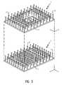
- FIG. 3shows a perspective view of the manner in which the heat sink layers of FIGS. 1 and 2 may be aligned to form the stacked arrangement of FIG. 4 .
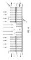
- FIGS. 4shows a cross-sectional view of the heat sink layers of FIGS. 1-3 as assembled to form a two-layer heat sink stack using forced air cooling.
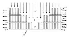
- FIG. 5shows a cross-sectional view of a three-layer heat sink stack using forced air cooling.
- FIG. 6shows a cross-sectional view of a three-layer heat sink stack using natural convection cooling.
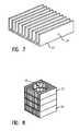
- FIG. 7shows a perspective view of a heat sink layer of vertical plate fins formed on a base plate and extending from the X-Y plane of the plate into the Z direction.
- FIG. 8shows a perspective view of the manner in which four layers of vertical plate fin heat sinks may be stacked with each ascending layer having a successively larger opening in central region thereof.
- FIG. 1there is shown a perspective view of a typical heat sink layer 1 having pin fins formed on a base plate.
- the heat sink layer 1may be made of a metal, such as aluminum, and may be formed, for example by extrusion or casting.
- the elements of the heat sink depicted in FIG. 1, as well as those depicted in FIGS. 2-8,are not to scale nor is their depiction intended to convey the relative proportions of these elements. These depictions are merely intended to aid in understanding the heat sink features in accordance with present invention.
- the density and pitch of the array of pins 3may be greater or less than shown, and the height and cross-sectional area of the pins may be varied.
- the cross-section of pins 3are depicted as being round, other shapes, such as square or rectangular pins may be easier to fabricate, depending upon the manufacturing process employed.
- FIG. 2shows a perspective view of a heat sink layer 7 , similar to that shown in FIG. 1, having however, an opening 9 in the central region thereof.
- a square section of base plate 11 , and pins 13 that would otherwise be formed thereon,have been removed.
- the size of opening 9may be varied to achieve optimum performance in accordance with the particular application.
- the shape of opening 9may be varied such that it could be rectangular, round, triangular or some form of irregular shape.
- FIG. 3shows a perspective view of the manner in which the heat sink layers 1 and 7 of FIGS. 1 and 2 may be aligned to form the pyramidic stacked heat sink structure 15 shown in FIG. 4 .
- heat sink layer 7is aligned and mounted on heat sink layer 1 .
- the base plate 11 of heat sink layer 7may be bonded to the fin pins 3 of heat sink layer 1 with a high thermal conduction epoxy or with solder alloys (dip-brazing), as is well known to those skilled in the art.
- pins 3may be uniformly arranged on plate 5 , as shown in FIGS. 1 and 3 or, alternatively, some pins 3 may be removed in the central portion 18 , as shown in FIG. 4 . It can be seen that fewer pins have been removed from plate 5 than have been removed from plate 1 l. Depending upon the application, a small opening (not shown), concentric with the pins removed from plate 5 , may also be employed. However, where the application involves plate 5 in direct thermal contact with a continuous, flat surface, such as the surface of a cover plate or silicon chip, little benefit is obtained in having such an opening.
- heat sink layersBy stacking the heat sink layers, as shown in FIG. 4, increased height in the vertical cooling surface is achieved in a simple manner. As shown in FIGS. 5 and 6, additional heat sink layers may be added to the stack in accordance with the requirements of the particular application being addressed so that three or four or more layers of heat sinks may be stacked in pyramidic fashion. Such an approach to gaining vertical cooling surface otherwise eliminates fabricating single layer tall fins with its attendant manufacturing difficulties.
- the individual heat sink layers used to form the pyramidal stack in accordance with the present inventionmay be mass manufactured heat sinks formed by conventional extrusion or casting. These latter methods of manufacture do not allow for fabricating heat sinks with the high aspect ratios required for increased heat transfer in a constrained X-Y space.
- pin finsare shown in the stacked heat sinks of FIGS. 4-6, it is clear that plate fins, folded fins, corrugated fins, etc. could just as well be employed. The fins of all such arrangements would, in similar fashion to the disclosed pin fins, be vertical to its supporting base plate which base plate abuts the heat generating surface to be cooled.
- FIG. 4depicts cooling by forced air convection.
- airis impinged upon the stacked heat sinks from the top.
- a portion of the airflowexits from the side of the top of heat sink layer 7 .
- the remaining portion of the airpasses through opening 9 in the base 11 of top layer 7 and impinges upon the bottom heat sink layer 1 .
- the airthen passes horizontally through the bottom heat sink layer and exits from the sides thereof.
- FIG. 5shows the cross-sectional arrangement of FIG. 4 with a third heat sink layer 17 stacked thereon to form stacked heat sink structure 22 .
- the central opening 19 (with removed pins) in base plate 21 of heat sink layer 17is concentric or centered with and larger than opening 9 (with removed pins) in base plate 11 of heat sink layer 7 and opening 9 in base plate 11 is, in turn, concentric or centered with and larger than the removed pin region 18 (and any small opening) in base plate 5 .
- the arrangement of FIG. 5also depicts cooling by forced convection. As shown by the arrows, the air flow pattern is the same as that shown and described with regard to FIG.
- FIG. 6depicts the structural arrangement of FIG. 5 using natural convection cooling.
- airenters each of the layers of stacked heat sinks from the sides and moves through pin fins toward the center and then rises up through the respective openings 18 , 9 and 18 .
- the respective openings in the base platesallow the hot air to flow upward and away from the stacked heat sinks.
- the removal of fin pins in the central regionincreases overall efficiency by removing what would be the least efficient pin fins and reducing heat sink weight. Weight reduction is particularly advantageous in organic packaging where the stresses from the heat sink can alter the mechanics of the chip carrier.
- the stacked heat sink structure in accordance with the present inventionneed not be limited to a single material. Accordingly, where required, the individual heat sink layers of the stacked heat sink structure can be of different materials/thicknesses so that the pyramidic heat sink structure attaches optimally with other mating surfaces with respect to thermomechanical properties.
- the material of the bottom most layercan be selected to have a CTE, for example, closely matching that of the adjacent chip or its cover plate.
- cover platesare made of copper or aluminum and the bottom layer of the heat sink stack could, similarly, be made of this material.
- each layermay be of a different fin type, shape or density.
- the shape of the central openingscan also be different from layer to layer. Fin thickness, shape or density may be made to vary from layer to layer or can be made to vary within a given layer.
- the size of central openings in the heat sink layerscan be optimized to achieve a lower pressure drop in forced convection cooling where machines are used in an environment with strict pressure drop requirements.
- FIG. 7shows a perspective view of a plate fm heat sink layer with an array of vertical plate fins 20 extending from base plate 23 .
- FIG. 8shows a perspective view of a four layer stack vertical plate fm heat sink structure, in accordance with the present invention. As shown in FIG. 8, the central opening region 25 in each layer is circular with each successive layer below the top layer 27 having a smaller concentric circular opening than the layer above. Bottom layer 29 may have an opening or may not, depending upon the particular application. Although the opening is shown as being circular, it is clear that any of a variety of opening shapes may be employed.
Landscapes
- Engineering & Computer Science (AREA)
- Physics & Mathematics (AREA)
- Computer Hardware Design (AREA)
- Materials Engineering (AREA)
- Condensed Matter Physics & Semiconductors (AREA)
- General Physics & Mathematics (AREA)
- Chemical & Material Sciences (AREA)
- Microelectronics & Electronic Packaging (AREA)
- Power Engineering (AREA)
- Thermal Sciences (AREA)
- Mechanical Engineering (AREA)
- General Engineering & Computer Science (AREA)
- Cooling Or The Like Of Semiconductors Or Solid State Devices (AREA)
- Cooling Or The Like Of Electrical Apparatus (AREA)
Abstract
Description
Claims (18)
Priority Applications (1)
| Application Number | Priority Date | Filing Date | Title |
|---|---|---|---|
| US10/125,302US6622786B1 (en) | 2002-04-17 | 2002-04-17 | Heat sink structure with pyramidic and base-plate cut-outs |
Applications Claiming Priority (1)
| Application Number | Priority Date | Filing Date | Title |
|---|---|---|---|
| US10/125,302US6622786B1 (en) | 2002-04-17 | 2002-04-17 | Heat sink structure with pyramidic and base-plate cut-outs |
Publications (1)
| Publication Number | Publication Date |
|---|---|
| US6622786B1true US6622786B1 (en) | 2003-09-23 |
Family
ID=28041133
Family Applications (1)
| Application Number | Title | Priority Date | Filing Date |
|---|---|---|---|
| US10/125,302Expired - Fee RelatedUS6622786B1 (en) | 2002-04-17 | 2002-04-17 | Heat sink structure with pyramidic and base-plate cut-outs |
Country Status (1)
| Country | Link |
|---|---|
| US (1) | US6622786B1 (en) |
Cited By (25)
| Publication number | Priority date | Publication date | Assignee | Title |
|---|---|---|---|---|
| US20050145365A1 (en)* | 2003-12-24 | 2005-07-07 | Hung-Shen Chang | Guide flow heat sink |
| US20060023423A1 (en)* | 2004-07-30 | 2006-02-02 | Via Technologies, Inc. | Expandable heat sink |
| US7056116B2 (en)* | 2004-10-26 | 2006-06-06 | Ultradent Products, Inc. | Heat sink for dental curing light comprising a plurality of different materials |
| US20060219386A1 (en)* | 2005-04-01 | 2006-10-05 | Delta Electronics, Inc. | Heat dissipating assembly with composite heat dissipating structure |
| EP1733822A3 (en)* | 2005-05-18 | 2007-01-31 | M.Pore Gmbh | Metallic distance fabric with rigid shape, method for its manufacture and use |
| US20080291640A1 (en)* | 2006-12-22 | 2008-11-27 | Abb Technology Ag | Electronic device with a base plate |
| US20090314467A1 (en)* | 2008-06-18 | 2009-12-24 | International Business Machines Corporation | Cooling apparatus and method of fabrication thereof with jet impingement structure integrally formed on thermally conductive pin fins |
| US20100193162A1 (en)* | 2009-02-05 | 2010-08-05 | Wistron Corporation | Heat dissipation device |
| US20120291719A1 (en)* | 2011-05-19 | 2012-11-22 | Bock Water Heaters, Inc. | Water Heater with Multiple Heat Exchanging Stacks |
| US20130199767A1 (en)* | 2012-02-02 | 2013-08-08 | International Business Machines Corporation | Compliant pin fin heat sink and methods |
| US20130269920A1 (en)* | 2012-04-17 | 2013-10-17 | Molex Incorporated | Cooling device |
| US20140311725A1 (en)* | 2011-11-02 | 2014-10-23 | National University Of Singapore | Heat sink assembly apparatus |
| US20150068719A1 (en)* | 2013-09-06 | 2015-03-12 | Delta Electronics, Inc. | Heat sink |
| US20170003081A1 (en)* | 2015-06-30 | 2017-01-05 | Hs Marston Aerospace Limited | Heat Exchangers |
| US20170314877A1 (en)* | 2015-01-15 | 2017-11-02 | Huawei Technologies Co., Ltd. | Heat Dissipation Apparatus |
| USD822625S1 (en)* | 2016-04-26 | 2018-07-10 | Showa Denko K.K. | Fin for heat exchanger |
| US20190113292A1 (en)* | 2017-10-13 | 2019-04-18 | Hamilton Sundstrand Corporation | Net shape moldable thermally conductive materials |
| US20200194979A1 (en)* | 2018-12-14 | 2020-06-18 | Robroy Industries - Texas, LLC | Electrical Conduit System Having Improved Sealing Between Joints |
| USRE48664E1 (en)* | 2015-03-10 | 2021-07-27 | Toshiba Memory Corporation | Electronic device |
| US20220377935A1 (en)* | 2021-05-24 | 2022-11-24 | Aptiv Technologies Limited | Cooling Device and Heatsink Assembly Incorporating the Same |
| US11631624B2 (en)* | 2018-12-11 | 2023-04-18 | Advanced Micro Devices, Inc. | Semiconductor chip package with spring biased lid |
| US11788801B2 (en)* | 2017-10-13 | 2023-10-17 | Volvo Truck Corporation | Heat exchanger and an additive manufacturing method for manufacturing a heat exchanger |
| DE102022206943A1 (en)* | 2022-07-07 | 2024-01-18 | Zf Friedrichshafen Ag | Three-dimensional cooling structure for power semiconductors and method for producing same |
| US11982500B2 (en) | 2013-09-06 | 2024-05-14 | Delta Electronics, Inc. | Heat sink |
| US12041754B1 (en)* | 2021-05-07 | 2024-07-16 | Core Scientific, Inc. | Heat sink that varies in height |
Citations (21)
| Publication number | Priority date | Publication date | Assignee | Title |
|---|---|---|---|---|
| US2897419A (en) | 1957-03-01 | 1959-07-28 | Bell Telephone Labor Inc | Semiconductor diode |
| US4611238A (en) | 1982-05-05 | 1986-09-09 | Burroughs Corporation | Integrated circuit package incorporating low-stress omnidirectional heat sink |
| US4688077A (en) | 1982-03-29 | 1987-08-18 | Fujitsu Limited | Semiconductor device having radiator |
| JPH01132146A (en) | 1987-11-17 | 1989-05-24 | Mitsubishi Electric Corp | Semiconductor device |
| US5072787A (en)* | 1989-08-30 | 1991-12-17 | Nakamichi Corporation | Finned heat sink |
| US5437328A (en)* | 1994-04-21 | 1995-08-01 | International Business Machines Corporation | Multi-stage heat sink |
| US5491362A (en) | 1992-04-30 | 1996-02-13 | Vlsi Technology, Inc. | Package structure having accessible chip |
| US5504650A (en)* | 1992-05-28 | 1996-04-02 | Fujitsu Limited | Heat sink for cooling a heat producing element and application |
| US5583746A (en)* | 1994-12-12 | 1996-12-10 | Tennmax Trading Corp. | Heat sink assembly for a central processing unit of a computer |
| US5654587A (en) | 1993-07-15 | 1997-08-05 | Lsi Logic Corporation | Stackable heatsink structure for semiconductor devices |
| US5655600A (en)* | 1995-06-05 | 1997-08-12 | Alliedsignal Inc. | Composite plate pin or ribbon heat exchanger |
| US5689404A (en)* | 1995-03-17 | 1997-11-18 | Fujitsu, Ltd. | Heat sink having air movement device positioned among tins and between heating elements |
| US5773886A (en) | 1993-07-15 | 1998-06-30 | Lsi Logic Corporation | System having stackable heat sink structures |
| US5794684A (en) | 1996-11-08 | 1998-08-18 | Jacoby; John | Stacked fin heat sink construction and method of manufacturing the same |
| US5880933A (en) | 1997-08-18 | 1999-03-09 | Daimlerchrysler Corporation | Heat sinking module cover |
| US5896917A (en)* | 1996-02-22 | 1999-04-27 | Lemont Aircraft Corporation | Active heat sink structure with flow augmenting rings and method for removing heat |
| US6025991A (en) | 1998-02-16 | 2000-02-15 | Alps Electric Co., Ltd. | Electronic apparatus having heat dissipating arrangement |
| US6097603A (en) | 1997-10-22 | 2000-08-01 | Thermalloy, Incorporated | Heat sink for direct attachment to surface mount electronic device packages |
| US6196302B1 (en)* | 1999-03-16 | 2001-03-06 | Wen-Hao Chuang | Heat sink with multi-layer dispersion space |
| US6202738B1 (en) | 1996-12-03 | 2001-03-20 | Minebea Company, Ltd. | Assembled structure having an enlarged heat transfer area for heat radiation therefrom |
| US6267178B1 (en)* | 1999-05-14 | 2001-07-31 | Yun-Ching Chen | Built-up heat exchanger |
- 2002
- 2002-04-17USUS10/125,302patent/US6622786B1/ennot_activeExpired - Fee Related
Patent Citations (22)
| Publication number | Priority date | Publication date | Assignee | Title |
|---|---|---|---|---|
| US2897419A (en) | 1957-03-01 | 1959-07-28 | Bell Telephone Labor Inc | Semiconductor diode |
| US4688077A (en) | 1982-03-29 | 1987-08-18 | Fujitsu Limited | Semiconductor device having radiator |
| US4611238A (en) | 1982-05-05 | 1986-09-09 | Burroughs Corporation | Integrated circuit package incorporating low-stress omnidirectional heat sink |
| JPH01132146A (en) | 1987-11-17 | 1989-05-24 | Mitsubishi Electric Corp | Semiconductor device |
| US5072787A (en)* | 1989-08-30 | 1991-12-17 | Nakamichi Corporation | Finned heat sink |
| US5491362A (en) | 1992-04-30 | 1996-02-13 | Vlsi Technology, Inc. | Package structure having accessible chip |
| US5504650A (en)* | 1992-05-28 | 1996-04-02 | Fujitsu Limited | Heat sink for cooling a heat producing element and application |
| US5900670A (en) | 1993-07-15 | 1999-05-04 | Lsi Logic Corporation | Stackable heatsink structures for semiconductor devices |
| US5654587A (en) | 1993-07-15 | 1997-08-05 | Lsi Logic Corporation | Stackable heatsink structure for semiconductor devices |
| US5773886A (en) | 1993-07-15 | 1998-06-30 | Lsi Logic Corporation | System having stackable heat sink structures |
| US5437328A (en)* | 1994-04-21 | 1995-08-01 | International Business Machines Corporation | Multi-stage heat sink |
| US5583746A (en)* | 1994-12-12 | 1996-12-10 | Tennmax Trading Corp. | Heat sink assembly for a central processing unit of a computer |
| US5689404A (en)* | 1995-03-17 | 1997-11-18 | Fujitsu, Ltd. | Heat sink having air movement device positioned among tins and between heating elements |
| US5655600A (en)* | 1995-06-05 | 1997-08-12 | Alliedsignal Inc. | Composite plate pin or ribbon heat exchanger |
| US5896917A (en)* | 1996-02-22 | 1999-04-27 | Lemont Aircraft Corporation | Active heat sink structure with flow augmenting rings and method for removing heat |
| US5794684A (en) | 1996-11-08 | 1998-08-18 | Jacoby; John | Stacked fin heat sink construction and method of manufacturing the same |
| US6202738B1 (en) | 1996-12-03 | 2001-03-20 | Minebea Company, Ltd. | Assembled structure having an enlarged heat transfer area for heat radiation therefrom |
| US5880933A (en) | 1997-08-18 | 1999-03-09 | Daimlerchrysler Corporation | Heat sinking module cover |
| US6097603A (en) | 1997-10-22 | 2000-08-01 | Thermalloy, Incorporated | Heat sink for direct attachment to surface mount electronic device packages |
| US6025991A (en) | 1998-02-16 | 2000-02-15 | Alps Electric Co., Ltd. | Electronic apparatus having heat dissipating arrangement |
| US6196302B1 (en)* | 1999-03-16 | 2001-03-06 | Wen-Hao Chuang | Heat sink with multi-layer dispersion space |
| US6267178B1 (en)* | 1999-05-14 | 2001-07-31 | Yun-Ching Chen | Built-up heat exchanger |
Non-Patent Citations (2)
| Title |
|---|
| P.M. Connors, Sep. 1974, IBM Technical Disclosure Bulletin, vol. 17 No. 4,.** |
| PCT/US83/00661, International Filing Date: May 5, 1983, Priority Application No.: 375,069 Priority Date: May 5, 1982, Priority Country: US, Inventors: Lewis, et al., Entitled: "Low-Stress-Inducing Omnidirectional Heat Sink", International Publication No.: WO 83/03924, International Publication Date: Nov. 10, 1983. |
Cited By (42)
| Publication number | Priority date | Publication date | Assignee | Title |
|---|---|---|---|---|
| US20050145365A1 (en)* | 2003-12-24 | 2005-07-07 | Hung-Shen Chang | Guide flow heat sink |
| US20060023423A1 (en)* | 2004-07-30 | 2006-02-02 | Via Technologies, Inc. | Expandable heat sink |
| US7056116B2 (en)* | 2004-10-26 | 2006-06-06 | Ultradent Products, Inc. | Heat sink for dental curing light comprising a plurality of different materials |
| US20060219386A1 (en)* | 2005-04-01 | 2006-10-05 | Delta Electronics, Inc. | Heat dissipating assembly with composite heat dissipating structure |
| EP1733822A3 (en)* | 2005-05-18 | 2007-01-31 | M.Pore Gmbh | Metallic distance fabric with rigid shape, method for its manufacture and use |
| US8050054B2 (en)* | 2006-12-22 | 2011-11-01 | Abb Technology Ag | Electronic device with a base plate |
| US20080291640A1 (en)* | 2006-12-22 | 2008-11-27 | Abb Technology Ag | Electronic device with a base plate |
| US20090314467A1 (en)* | 2008-06-18 | 2009-12-24 | International Business Machines Corporation | Cooling apparatus and method of fabrication thereof with jet impingement structure integrally formed on thermally conductive pin fins |
| US8266802B2 (en)* | 2008-06-18 | 2012-09-18 | International Business Machines Corporation | Cooling apparatus and method of fabrication thereof with jet impingement structure integrally formed on thermally conductive pin fins |
| US20100193162A1 (en)* | 2009-02-05 | 2010-08-05 | Wistron Corporation | Heat dissipation device |
| US20120291719A1 (en)* | 2011-05-19 | 2012-11-22 | Bock Water Heaters, Inc. | Water Heater with Multiple Heat Exchanging Stacks |
| US8807093B2 (en)* | 2011-05-19 | 2014-08-19 | Bock Water Heaters, Inc. | Water heater with multiple heat exchanging stacks |
| US10420254B2 (en)* | 2011-11-02 | 2019-09-17 | National University Of Singapore | Heat sink assembly apparatus |
| US20140311725A1 (en)* | 2011-11-02 | 2014-10-23 | National University Of Singapore | Heat sink assembly apparatus |
| US20170236770A1 (en)* | 2012-02-02 | 2017-08-17 | International Business Machines Corporation | Compliant pin fin heat sink and methods |
| US20130199767A1 (en)* | 2012-02-02 | 2013-08-08 | International Business Machines Corporation | Compliant pin fin heat sink and methods |
| US9425124B2 (en)* | 2012-02-02 | 2016-08-23 | International Business Machines Corporation | Compliant pin fin heat sink and methods |
| CN103247583A (en)* | 2012-02-02 | 2013-08-14 | 国际商业机器公司 | Compliant pin fin heat sink and methods |
| US11158565B2 (en) | 2012-02-02 | 2021-10-26 | International Business Machines Corporation | Compliant pin fin heat sink and methods |
| US9997435B2 (en)* | 2012-02-02 | 2018-06-12 | International Business Machines Corporation | Compliant pin fin heat sink and methods |
| US20160081225A1 (en)* | 2012-04-17 | 2016-03-17 | Molex, Llc | Stackable rotated heat sink |
| US20130269920A1 (en)* | 2012-04-17 | 2013-10-17 | Molex Incorporated | Cooling device |
| US20150068719A1 (en)* | 2013-09-06 | 2015-03-12 | Delta Electronics, Inc. | Heat sink |
| US11982500B2 (en) | 2013-09-06 | 2024-05-14 | Delta Electronics, Inc. | Heat sink |
| US10627172B2 (en)* | 2015-01-15 | 2020-04-21 | Huawei Technologies Co., Ltd. | Heat dissipation apparatus |
| US20170314877A1 (en)* | 2015-01-15 | 2017-11-02 | Huawei Technologies Co., Ltd. | Heat Dissipation Apparatus |
| USRE50236E1 (en) | 2015-03-10 | 2024-12-10 | Kioxia Corporation | Electronic device |
| USRE48664E1 (en)* | 2015-03-10 | 2021-07-27 | Toshiba Memory Corporation | Electronic device |
| US10544991B2 (en)* | 2015-06-30 | 2020-01-28 | Hs Marston Aerospace Ltd. | Heat exchangers |
| US20170003081A1 (en)* | 2015-06-30 | 2017-01-05 | Hs Marston Aerospace Limited | Heat Exchangers |
| USD822625S1 (en)* | 2016-04-26 | 2018-07-10 | Showa Denko K.K. | Fin for heat exchanger |
| US11788801B2 (en)* | 2017-10-13 | 2023-10-17 | Volvo Truck Corporation | Heat exchanger and an additive manufacturing method for manufacturing a heat exchanger |
| US10976120B2 (en)* | 2017-10-13 | 2021-04-13 | Hamilton Sundstrand Corporation | Net shape moldable thermally conductive materials |
| US20190113292A1 (en)* | 2017-10-13 | 2019-04-18 | Hamilton Sundstrand Corporation | Net shape moldable thermally conductive materials |
| US11815317B2 (en) | 2017-10-13 | 2023-11-14 | Hamilton Sundstrand Corporation | Net shape moldable thermally conductive materials |
| US11631624B2 (en)* | 2018-12-11 | 2023-04-18 | Advanced Micro Devices, Inc. | Semiconductor chip package with spring biased lid |
| US10951015B2 (en)* | 2018-12-14 | 2021-03-16 | Robroy Industries—Texas, LLC | Electrical conduit system having improved sealing between joints |
| US20200194979A1 (en)* | 2018-12-14 | 2020-06-18 | Robroy Industries - Texas, LLC | Electrical Conduit System Having Improved Sealing Between Joints |
| US12041754B1 (en)* | 2021-05-07 | 2024-07-16 | Core Scientific, Inc. | Heat sink that varies in height |
| US20220377935A1 (en)* | 2021-05-24 | 2022-11-24 | Aptiv Technologies Limited | Cooling Device and Heatsink Assembly Incorporating the Same |
| US12185493B2 (en)* | 2021-05-24 | 2024-12-31 | Aptiv Technologies AG | Cooling device and heatsink assembly incorporating the same |
| DE102022206943A1 (en)* | 2022-07-07 | 2024-01-18 | Zf Friedrichshafen Ag | Three-dimensional cooling structure for power semiconductors and method for producing same |
Similar Documents
| Publication | Publication Date | Title |
|---|---|---|
| US6622786B1 (en) | Heat sink structure with pyramidic and base-plate cut-outs | |
| US6615909B2 (en) | Corrugated matrix heat sink for cooling electronic components | |
| US6980438B2 (en) | Semiconductor package with heat dissipating structure | |
| KR100294873B1 (en) | LS Eye Package Cooling Wave Heat Sink Assembly | |
| US9179578B2 (en) | Semiconductor module and heat radiation member | |
| US6817405B2 (en) | Apparatus having forced fluid cooling and pin-fin heat sink | |
| US4964458A (en) | Flexible finned heat exchanger | |
| CN1092397C (en) | High performance, low cost multi-chip module package | |
| JPH07161883A (en) | Heat sink | |
| US20100019379A1 (en) | External heat sink for bare-die flip chip packages | |
| WO2013091441A1 (en) | Pop encapsulation structure | |
| EP4184563A1 (en) | Temperature control element utilized in device die packages | |
| KR102704716B1 (en) | Semiconductor package and method of manufacturing the same | |
| US7327028B2 (en) | Embedded heat spreader for folded stacked chip-scale package | |
| US20050034841A1 (en) | Integral chip lid and heat sink | |
| JP2008124187A (en) | Base for power module | |
| JP2008124187A6 (en) | Power module base | |
| CN100369243C (en) | Semiconductor package with heat dissipation structure | |
| JP7052923B2 (en) | Circuit board | |
| KR100504692B1 (en) | A Laminated Type Heat Sink | |
| CN115763405B (en) | A 3D stacked chip with embedded microchannel cooling structure | |
| CN222214169U (en) | Novel three-dimensional integrated circuit heat dissipation mechanism | |
| CN222530421U (en) | Substrate and semiconductor device | |
| JPH1032288A (en) | Heat sink with excellent heat dissipation performance | |
| JPH05102356A (en) | Heat dissipation fin |
Legal Events
| Date | Code | Title | Description |
|---|---|---|---|
| AS | Assignment | Owner name:INTERNATIONAL BUSINESS MACHINES CORPORATION, NEW Y Free format text:ASSIGNMENT OF ASSIGNORS INTEREST;ASSIGNORS:CALMIDI, VARAPRASAD V.;DARBHA, KRISHNA;SATHE, SANJEEV B.;AND OTHERS;REEL/FRAME:012837/0577;SIGNING DATES FROM 20020314 TO 20020414 | |
| FEPP | Fee payment procedure | Free format text:PAYOR NUMBER ASSIGNED (ORIGINAL EVENT CODE: ASPN); ENTITY STATUS OF PATENT OWNER: LARGE ENTITY | |
| FPAY | Fee payment | Year of fee payment:4 | |
| REMI | Maintenance fee reminder mailed | ||
| FPAY | Fee payment | Year of fee payment:8 | |
| SULP | Surcharge for late payment | Year of fee payment:7 | |
| AS | Assignment | Owner name:GOOGLE INC., CALIFORNIA Free format text:ASSIGNMENT OF ASSIGNORS INTEREST;ASSIGNOR:INTERNATIONAL BUSINESS MACHINES CORPORATION;REEL/FRAME:026664/0866 Effective date:20110503 | |
| REMI | Maintenance fee reminder mailed | ||
| LAPS | Lapse for failure to pay maintenance fees | ||
| STCH | Information on status: patent discontinuation | Free format text:PATENT EXPIRED DUE TO NONPAYMENT OF MAINTENANCE FEES UNDER 37 CFR 1.362 | |
| FP | Lapsed due to failure to pay maintenance fee | Effective date:20150923 | |
| AS | Assignment | Owner name:GOOGLE LLC, CALIFORNIA Free format text:CHANGE OF NAME;ASSIGNOR:GOOGLE INC.;REEL/FRAME:044142/0357 Effective date:20170929 |