US6622427B2 - Spraying a liquid on plants by means of a spraying assembly mounted on a pair of wires - Google Patents
Spraying a liquid on plants by means of a spraying assembly mounted on a pair of wiresDownload PDFInfo
- Publication number
- US6622427B2 US6622427B2US10/105,511US10551102AUS6622427B2US 6622427 B2US6622427 B2US 6622427B2US 10551102 AUS10551102 AUS 10551102AUS 6622427 B2US6622427 B2US 6622427B2
- Authority
- US
- United States
- Prior art keywords
- sprayer
- rod
- holder
- spraying assembly
- assembly according
- Prior art date
- Legal status (The legal status is an assumption and is not a legal conclusion. Google has not performed a legal analysis and makes no representation as to the accuracy of the status listed.)
- Expired - Lifetime
Links
Images


Classifications
- A—HUMAN NECESSITIES
- A01—AGRICULTURE; FORESTRY; ANIMAL HUSBANDRY; HUNTING; TRAPPING; FISHING
- A01G—HORTICULTURE; CULTIVATION OF VEGETABLES, FLOWERS, RICE, FRUIT, VINES, HOPS OR SEAWEED; FORESTRY; WATERING
- A01G25/00—Watering gardens, fields, sports grounds or the like
- A01G25/09—Watering arrangements making use of movable installations on wheels or the like
- A—HUMAN NECESSITIES
- A01—AGRICULTURE; FORESTRY; ANIMAL HUSBANDRY; HUNTING; TRAPPING; FISHING
- A01C—PLANTING; SOWING; FERTILISING
- A01C23/00—Distributing devices specially adapted for liquid manure or other fertilising liquid, including ammonia, e.g. transport tanks or sprinkling wagons
- A01C23/04—Distributing under pressure; Distributing mud; Adaptation of watering systems for fertilising-liquids
- A01C23/042—Adding fertiliser to watering systems
- A—HUMAN NECESSITIES
- A01—AGRICULTURE; FORESTRY; ANIMAL HUSBANDRY; HUNTING; TRAPPING; FISHING
- A01G—HORTICULTURE; CULTIVATION OF VEGETABLES, FLOWERS, RICE, FRUIT, VINES, HOPS OR SEAWEED; FORESTRY; WATERING
- A01G13/00—Protection of plants
- A01G13/06—Devices for generating heat, smoke or fog in gardens, orchards or forests, e.g. to prevent damage by frost
- A01G13/065—Frost protection by generating fog or by spraying
- A—HUMAN NECESSITIES
- A01—AGRICULTURE; FORESTRY; ANIMAL HUSBANDRY; HUNTING; TRAPPING; FISHING
- A01G—HORTICULTURE; CULTIVATION OF VEGETABLES, FLOWERS, RICE, FRUIT, VINES, HOPS OR SEAWEED; FORESTRY; WATERING
- A01G17/00—Cultivation of hops, vines, fruit trees, or like trees
- A01G17/04—Supports for hops, vines, or trees
- A01G17/06—Trellis-work
Definitions
- This inventionrelates to sprayers for leafy plants, in particular for use with plants that grow in rows on two or more wires extending between supporting stakes, for spraying thereon anti-frost liquids, chemicals or the like.
- the methodin accordance with one aspect of the present invention, includes the steps of:
- At least one spraying assemblyincluding a sprayer with at least one spraying nozzle and a sprayer holder with a rigid rod and upper and lower holder members mounted on said rod, one of said holder members having a sprayer seat for fixedly supporting said sprayer in a predetermined orientation relative to said rod;
- FIG. 1Another aspect of the present invention is connected with a spraying assembly for mounting a sprayer on a pair of upper and lower wires parallel to each other and extending between wire-supporting stakes.
- the assemblycomprising a sprayer having at least one nozzle adapted for fluid connection with a source of said liquid, and a sprayer holder in the form of a rigid rod and upper and lower holder members mounted on said rod and having clamping means for being clamped to the respective upper and lower wires, one of said holder members having a sprayer seat for fixedly supporting said sprayer in a predetermined orientation relative to said rod.
- Still another aspect of the present inventionis connected with a holder for a sprayer having at least one nozzle, the holder comprising a rigid rod and upper and lower holder members mounted on said rod, one of said holder members having a sprayer seat for fixedly supporting said sprayer in a predetermined orientation relative to said rod.
- the holderis adapted for mounting on a pair of parallel wires and said upper and lower members have means for being clamped thereto.
- the sprayer assemblyWhen the sprayer assembly is mounted on two wires in accordance with the method of the present invention, the sprayer appears to be rigidly fixed in place in a required orientation relative to plants to be sprayed, due to the combined effect of the rigid rod and the clamping means of the upper and lower holder members.
- the method of the present inventionis used for spraying plants such as, for example, vine-stacks, growing in a row on at least said upper and lower wires, where a plurality of assemblies of the present invention may be mounted between the wire supporting stakes.
- said sprayerhas two nozzles facing in diametrically opposite directions perpendicular to an imaginary plane passing through said rod and a common vertical axis of the holder members. The sprayer assembly is then mounted on the upper and lower wires so that said imaginary plane is perpendicular thereto, whereby it is ensured that said nozzles are directed along said wires in two opposite directions.
- the sprayerwhen mounted in the sprayer holder of the present invention, may always be protected by the sprayer holder from any contact with agricultural machinery, such as vine-dressing machines.
- the sprayeris always kept in its fixed position relative to the row of vine-stacks, whereby any necessity of its adjustment is eliminated.
- the assemblyhas completely self-sufficient mounting means independent of the wire-supporting stakes and, therefore, a plurality of such assemblies may be mounted at any appropriate locations along the wires with any required pitch therebetween.
- the arrangement of the spraying assemblies on the wiresenables them to follow any trajectory of plant rows, whereby any need in additional ‘compensating’ sprayers is eliminated.
- the assemblyis suitable for a range of diameters of the wires and is adapted for the adjustment to any distance between the wires.
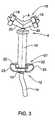
- FIG. 1is a schematic view of a spraying assembly of the present invention, mounted on two wires;
- FIG. 2is a perspective view of a sprayer holder used in the spraying assembly shown in FIG. 1;
- FIG. 3is a perspective view of a sprayer used in the spraying assembly shown in FIG. 1;
- FIG. 4is a perspective view of an upper member of the sprayer holder shown in FIG. 32.
- FIGS. 5 and 6are views of the spraying assembly shown in FIG. 1, in the respective directions along and perpendicular to the wires, on which the assembly is mounted.
- a spraying assembly 1 of the present inventionis designed for strip spraying a row of plants P growing on a plurality of wires and it is adapted for being mounted on an upper wire W 1 and a lower wire W 2 having a distance D therebetween.
- the wiresextend between wire-supporting stakes that are not shown.
- the assembly 1comprises a sprayer holder 2 and a sprayer 4 mounted in the sprayer holder 2 and adapted for fluid connection with a source of liquid to be sprayed (not shown).
- the liquidmay, for example, be water or other frost prevention composition.
- the sprayer 4has a cylindrical body 10 extending along an axis A, having an upstream end 12 formed with a liquid inlet 13 to be connected by a hose 14 to a pipe communicating with the source of liquid, and a downstream end 16 carrying a spraying head 18 .
- the spraying head 18has two nozzles 19 connected with the sprayer's body by corresponding necks 20 and facing in two diametrically opposite directions relative to the axis A.
- the necks 20 and, consequently, the nozzles 19are in fluid communication with the liquid inlet 13 .
- the sprayer 4may have any appropriate internal design and, for example, it may be a STRIPNET emitter manufactured by Netafim “Drip Irrigation” (C. S.) Ltd, Israel. It should be noted that, since the sprayer 4 does not constitute a subject matter of the present invention, its internal design will not be described in the present application in more detail.
- the sprayer 4is further provided with a locking arrangement 21 , either attached thereto or formed integrally therewith, for the fixation of the sprayer in its position in the sprayer holder 2 .
- the locking arrangementis preferably located adjacent the upstream end 12 of the sprayer, but this location may be anywhere along its length.
- the locking arrangementincludes ears 22 that extend outwardly from the periphery of the sprayer's body 10 and are oriented in the same manner, relative to the axis A, as the nozzles 19 .
- the ears 22have locking recesses 23 on both sides thereof.
- the sprayer holder 2comprises a rigid rod 30 and upper and lower holder members 32 and 34 mounted thereon.
- the rod 30has a length essentially exceeding the distance D between the upper and lower wires W 1 and W 2 , on which the entire assembly is to be mounted as shown in FIG. 1 .
- the upper holder member 32shown in more detail in FIG. 4, has an elongated tubular shape and upper and lower ends 36 and 38 .
- the holder member 32has an oval cross-sectional shape and, consequently, its first wall portions 40 have a distance d 1 therebetween, which is smaller than a distance d 2 between its second wall portions 42 . Both distances d 1 and d 2 are greater than the diameter of the cylindrical body portion 10 of the sprayer 4 , and the distance d 1 is at least slightly smaller than that between the nozzles 19 of the sprayer 4 .
- the first wall portions 40 of the holder member 32are formed with elongated cutouts 46 extending downwardly from the upper end 36 thereof and having a width that is broader than the neck portions 20 of the nozzles 19 and broader than the thickness of the ears 22 of the sprayer's locking arrangement 21 .
- the cutouts 46terminate at sockets 48 which are adapted to engage the ears 22 and which have locking projections 49 adapted to enter the locking recesses 23 of the ears.
- the first wall portions 40are further formed at the lower end 38 of the holder member 32 , with wedge-shaped slits 52 , constituting therebetween a wire-receiving slot 54 .
- One of the second wall portions 42 of the holder member 32is formed with a sleeve 55 for receiving therein the rod 30 with slide fit, enabling the movement of the holder member 32 around the rod 30 and also therealong, upon the application to the holder member 32 of a force exceeding a friction force between the sleeve 55 and the rod 30 .
- the lower holder member 34is similar to the upper holder member 32 in that it is also generally tubular, it has a wedge-shaped wire-receiving slot 56 and a pocket 60 for receiving therein the rod 30 so as to enable the rotation of the holder member 34 around the rod 30 , preventing it however from the movement therealong.
- the assembly 1further comprises clamping means 62 and 64 capable of tightening the respective wire-receiving slots 54 and 56 with the wires W 1 and W 2 passing therethrough, to prevent the movement of the upper and lower holder members 32 and 34 relative to the wires.
- the lower holder member 34is mounted first and secured by the clamping means 64 , and the position of the upper holder member 32 is subsequently adjusted, in accordance with the distance D between the wires, and secured by the clamping means 62 .
- their vertical axes(not shown) coincide and are parallel to the rod 30 , and an imaginary plane passing through the rod 30 and these vertical axes is perpendicular to the wires.
- the hose 14 thereofprojects from the lower end 38 of the member 32 and it may further be directed in a desired direction by passing through a corresponding ring portion 66 formed on the lower holder member 34 .
- the sprayer 4may be mounted in the sprayer holder 2 either before or after the latter is mounted on the wires, and the construction of sprayer holder ensures that the nozzles 19 face in two diametrically opposite directions along the wires, while the sprayer's body is fully accommodated by the sprayer holder.
- the assembly of the present invention and the method of its mounting on wiresmay differ from those described above and illustrated by the drawings, within the framework of the general concept of the invention.
- This general conceptis to use wires as a support for the spraying assembly, and it does not necessarily matter in which direction(s) the spraying needs to be performed.
- the assembly of the present inventionmay be located on wires extending perpendicularly to a row of plants and the sprayer then would need a nozzle facing perpendicularly to the wires.
- the sprayermay also have a rotating nozzle.
- the sprayer holder membersmay have different arrangements for their mounting on wires and they may be carried by an element other than the rod.
- the sprayer seatmay be arranged in a lower rather than upper holder member and it may have any appropriate design. Any other alternatives for different features of the present invention are possible, within the skills of an average person in the art.
Landscapes
- Life Sciences & Earth Sciences (AREA)
- Environmental Sciences (AREA)
- Engineering & Computer Science (AREA)
- Water Supply & Treatment (AREA)
- Botany (AREA)
- Soil Sciences (AREA)
- Forests & Forestry (AREA)
- Health & Medical Sciences (AREA)
- General Health & Medical Sciences (AREA)
- Toxicology (AREA)
- Catching Or Destruction (AREA)
Abstract
Description
This invention relates to sprayers for leafy plants, in particular for use with plants that grow in rows on two or more wires extending between supporting stakes, for spraying thereon anti-frost liquids, chemicals or the like.
In viticulture, it is know to prevent frost-damage of vines either by covering vine-stock rows with plastic film, such as for example suggested in WO 97/03553, or by spraying the vine-stocks with water. The latter is normally performed by sprayers that are either mounted on hoses installed above the vine-stock rows or are attached to stakes supporting wires on which each row grows. The sprayers may also be installed on a machine, such as a vine-dressing machine described in U.S. Pat. No. 4,333,266, adapted to pass between the vine-stock rows.
In accordance with different aspects of the present invention, there are provided a novel method and a novel spraying assembly for spraying a liquid on plants, and also a novel sprayer holder for use therein.
The method, in accordance with one aspect of the present invention, includes the steps of:
(a) providing at least a pair of upper and lower wires parallel to each other and extending between wire-supporting stakes;
(b) providing at least one spraying assembly including a sprayer with at least one spraying nozzle and a sprayer holder with a rigid rod and upper and lower holder members mounted on said rod, one of said holder members having a sprayer seat for fixedly supporting said sprayer in a predetermined orientation relative to said rod;
(c) clamping said upper and lower members to the respective upper and lower wires in a predetermined orientation relative thereto so that, upon disposing said sprayer in said seat, said at least one nozzle faces the plants; and
(d) providing a fluid connection between said nozzle and a source of said liquid.
Another aspect of the present invention is connected with a spraying assembly for mounting a sprayer on a pair of upper and lower wires parallel to each other and extending between wire-supporting stakes. The assembly comprising a sprayer having at least one nozzle adapted for fluid connection with a source of said liquid, and a sprayer holder in the form of a rigid rod and upper and lower holder members mounted on said rod and having clamping means for being clamped to the respective upper and lower wires, one of said holder members having a sprayer seat for fixedly supporting said sprayer in a predetermined orientation relative to said rod.
Still another aspect of the present invention is connected with a holder for a sprayer having at least one nozzle, the holder comprising a rigid rod and upper and lower holder members mounted on said rod, one of said holder members having a sprayer seat for fixedly supporting said sprayer in a predetermined orientation relative to said rod. The holder is adapted for mounting on a pair of parallel wires and said upper and lower members have means for being clamped thereto.
When the sprayer assembly is mounted on two wires in accordance with the method of the present invention, the sprayer appears to be rigidly fixed in place in a required orientation relative to plants to be sprayed, due to the combined effect of the rigid rod and the clamping means of the upper and lower holder members.
Preferably, the method of the present invention is used for spraying plants such as, for example, vine-stacks, growing in a row on at least said upper and lower wires, where a plurality of assemblies of the present invention may be mounted between the wire supporting stakes. In this case, it is preferable that said sprayer has two nozzles facing in diametrically opposite directions perpendicular to an imaginary plane passing through said rod and a common vertical axis of the holder members. The sprayer assembly is then mounted on the upper and lower wires so that said imaginary plane is perpendicular thereto, whereby it is ensured that said nozzles are directed along said wires in two opposite directions.
Thus, the sprayer, when mounted in the sprayer holder of the present invention, may always be protected by the sprayer holder from any contact with agricultural machinery, such as vine-dressing machines. The sprayer is always kept in its fixed position relative to the row of vine-stacks, whereby any necessity of its adjustment is eliminated. The assembly has completely self-sufficient mounting means independent of the wire-supporting stakes and, therefore, a plurality of such assemblies may be mounted at any appropriate locations along the wires with any required pitch therebetween. The arrangement of the spraying assemblies on the wires enables them to follow any trajectory of plant rows, whereby any need in additional ‘compensating’ sprayers is eliminated. The assembly is suitable for a range of diameters of the wires and is adapted for the adjustment to any distance between the wires.
In order to understand the invention and to see how it may be carried out in practice, a preferred embodiment will now be described, by way of non-limiting example only, with reference to the accompanying drawings, in which:
FIG. 1 is a schematic view of a spraying assembly of the present invention, mounted on two wires;
FIG. 2 is a perspective view of a sprayer holder used in the spraying assembly shown in FIG. 1;
FIG. 3 is a perspective view of a sprayer used in the spraying assembly shown in FIG. 1;
FIG. 4 is a perspective view of an upper member of the sprayer holder shown in FIG. 32; and
FIGS. 5 and 6 are views of the spraying assembly shown in FIG. 1, in the respective directions along and perpendicular to the wires, on which the assembly is mounted.
As illustrated in FIG. 1, a spraying assembly1 of the present invention is designed for strip spraying a row of plants P growing on a plurality of wires and it is adapted for being mounted on an upper wire W1 and a lower wire W2 having a distance D therebetween. The wires extend between wire-supporting stakes that are not shown.
As seen in FIG.1 and shown in detail in FIGS. 5 and 6, the assembly1 comprises asprayer holder 2 and asprayer 4 mounted in thesprayer holder 2 and adapted for fluid connection with a source of liquid to be sprayed (not shown). The liquid may, for example, be water or other frost prevention composition.
With reference to FIG. 3, thesprayer 4 has acylindrical body 10 extending along an axis A, having anupstream end 12 formed with aliquid inlet 13 to be connected by ahose 14 to a pipe communicating with the source of liquid, and a downstream end16 carrying a sprayinghead 18. The sprayinghead 18 has twonozzles 19 connected with the sprayer's body bycorresponding necks 20 and facing in two diametrically opposite directions relative to the axis A. Thenecks 20 and, consequently, thenozzles 19 are in fluid communication with theliquid inlet 13. Thesprayer 4 may have any appropriate internal design and, for example, it may be a STRIPNET emitter manufactured by Netafim “Drip Irrigation” (C. S.) Ltd, Israel. It should be noted that, since thesprayer 4 does not constitute a subject matter of the present invention, its internal design will not be described in the present application in more detail.
Thesprayer 4 is further provided with alocking arrangement 21, either attached thereto or formed integrally therewith, for the fixation of the sprayer in its position in thesprayer holder 2. The locking arrangement is preferably located adjacent theupstream end 12 of the sprayer, but this location may be anywhere along its length. The locking arrangement includesears 22 that extend outwardly from the periphery of the sprayer'sbody 10 and are oriented in the same manner, relative to the axis A, as thenozzles 19. Theears 22 have lockingrecesses 23 on both sides thereof.
With reference to FIG. 2, thesprayer holder 2 comprises arigid rod 30 and upper andlower holder members rod 30 has a length essentially exceeding the distance D between the upper and lower wires W1 and W2, on which the entire assembly is to be mounted as shown in FIG.1.
Theupper holder member 32, shown in more detail in FIG. 4, has an elongated tubular shape and upper andlower ends holder member 32 has an oval cross-sectional shape and, consequently, itsfirst wall portions 40 have a distance d1 therebetween, which is smaller than a distance d2 between itssecond wall portions 42. Both distances d1 and d2 are greater than the diameter of thecylindrical body portion 10 of thesprayer 4, and the distance d1 is at least slightly smaller than that between thenozzles 19 of thesprayer 4.
Thefirst wall portions 40 of theholder member 32 are formed withelongated cutouts 46 extending downwardly from theupper end 36 thereof and having a width that is broader than theneck portions 20 of thenozzles 19 and broader than the thickness of theears 22 of the sprayer'slocking arrangement 21. Thecutouts 46 terminate atsockets 48 which are adapted to engage theears 22 and which havelocking projections 49 adapted to enter thelocking recesses 23 of the ears. Thefirst wall portions 40 of theupper holder member 32 with theircutouts 46 and thesockets 48, together with thesecond wall portions 42 associated therewith, all constitute a sprayer seat, which is generally designated as50. Thefirst wall portions 40 are further formed at thelower end 38 of theholder member 32, with wedge-shaped slits 52, constituting therebetween a wire-receivingslot 54.
One of thesecond wall portions 42 of theholder member 32 is formed with asleeve 55 for receiving therein therod 30 with slide fit, enabling the movement of theholder member 32 around therod 30 and also therealong, upon the application to theholder member 32 of a force exceeding a friction force between thesleeve 55 and therod 30.
Reverting to FIG. 2, thelower holder member 34 is similar to theupper holder member 32 in that it is also generally tubular, it has a wedge-shaped wire-receivingslot 56 and apocket 60 for receiving therein therod 30 so as to enable the rotation of theholder member 34 around therod 30, preventing it however from the movement therealong.
The assembly1 further comprises clamping means62 and64 capable of tightening the respective wire-receiving slots lower holder members
For mounting thesprayer holder 2 on the wires W1 W2, thelower holder member 34 is mounted first and secured by the clamping means64, and the position of theupper holder member 32 is subsequently adjusted, in accordance with the distance D between the wires, and secured by the clamping means62. When the upper andlower holder members rod 30, and an imaginary plane passing through therod 30 and these vertical axes is perpendicular to the wires.
With reference to FIGS. 5 and 6, to mount thesprayer 4 in theupper holder member 32, itsbody 10 is inserted into theseat 50 so that theears 22 of thelocking arrangement 21 project outwardly through, and freely pass downwardly along, thecutouts 46 until these ears abut thelocking projections 49 of thesockets 48 of theupper holder member 32. Upon the application of a downward force on thesprayer 4, thelocking projections 49 enter thelocking recesses 23 of theears 22, thereby forming a snap joint and fixing the sprayer in place. In this position, the nozzles protrude from thecutouts 46 at theupper end 34 of theholder member 32, with theirneck portions 20 passing therethrough.
With thesprayer 4 being mounted in theupper holder member 32 as shown in FIGS. 5 and 6, thehose 14 thereof projects from thelower end 38 of themember 32 and it may further be directed in a desired direction by passing through acorresponding ring portion 66 formed on thelower holder member 34.
Thesprayer 4 may be mounted in thesprayer holder 2 either before or after the latter is mounted on the wires, and the construction of sprayer holder ensures that thenozzles 19 face in two diametrically opposite directions along the wires, while the sprayer's body is fully accommodated by the sprayer holder.
It should be understood that the assembly of the present invention and the method of its mounting on wires may differ from those described above and illustrated by the drawings, within the framework of the general concept of the invention. This general concept is to use wires as a support for the spraying assembly, and it does not necessarily matter in which direction(s) the spraying needs to be performed. Thus, for example, the assembly of the present invention may be located on wires extending perpendicularly to a row of plants and the sprayer then would need a nozzle facing perpendicularly to the wires. The sprayer may also have a rotating nozzle. The sprayer holder members may have different arrangements for their mounting on wires and they may be carried by an element other than the rod. The sprayer seat may be arranged in a lower rather than upper holder member and it may have any appropriate design. Any other alternatives for different features of the present invention are possible, within the skills of an average person in the art.
| List of references used in the drawings |
| 1 | |
| 2 | |
| 4 | |
| 10 | cylindrical body portion of the |
| 12 | upstream end of the |
| 13 | liquid inlet of the |
| 14 | hose |
| 16 | downstream end of the |
| 18 | spraying |
| 19 | |
| 20 | |
| 21 | locking |
| 22 | |
| 23 | locking recesses |
| 30 | |
| 32 | |
| 34 | |
| 36 | upper end of the |
| 38 | lower end of the |
| 40 | first wall portions of the |
| 42 | second wall portions of the |
| 46 | cutouts in the |
| 48 | |
| 49 | |
| 50 | |
| 52 | wedge-shaped |
| 54 | wire-receiving slot of the |
| 55 | |
| 56 | wire-receiving slot of the |
| 60 | pocket in the |
| 62 | clamping means of the |
| 64 | clamping means of the |
| 66 | ring portion in the lower holder member |
Claims (15)
1. A spraying assembly adapted for mounting on a pair of upper and lower wires parallel to each other, the assembly comprising a sprayer having at least one nozzle adapted for fluid communication with a source of liquid, and a sprayer holder in the form of a rigid rod and upper and lower holder members engaging said rod at spaced apart locations thereon and having each clamping means for being clamped to one of said upper and lower wires, one of said holder members having a sprayer seat capable of fixedly supporting said sprayer in a predetermined orientation relative to said rod.
2. A spraying assembly according toclaim 1 , wherein said sprayer has a vertical axis spaced apart from said rod and said clamping means are so constructed that, when the assembly is mounted on said wires, an imaginary plane passing through said axis and said rod is perpendicular to said wires.
3. A spraying assembly according toclaim 2 , wherein said sprayer has two nozzles and it is mounted in said sprayer seat so that said nozzles face in directions perpendicular to said imaginary plane.
4. A spraying assembly according toclaim 1 , wherein said sprayer seat is formed inside said one of the holder members, which accommodates said sprayer so that only said at least one nozzle projects from the holder member.
5. A spraying assembly according toclaim 1 , wherein said one of the holder members has a vertical axis spaced apart from, and parallel to, said rod, and said sprayer is so accommodated in said sprayer seat that said at least one nozzle projects from that holder member in the direction away from said vertical axis.
6. The spraying assembly according toclaim 1 , wherein said one of the holder members is a tubular body with a vertical axis spaced from said rod and said sprayer holder having an imaginary plane passing through said axis and said rod.
7. The spraying assembly according toclaim 6 , wherein said tubular body has said sprayer seat and wall portions formed with at least one cutout so that, when said sprayer is mounted in said seat, said at least one nozzle projects from said tubular body via said cutout in a spraying direction.
8. The spraying assembly according toclaim 7 , wherein said wall portions are oriented substantially parallel to said imaginary plane, to ensure that when the sprayer is mounted in the sprayer seat, said at least one nozzle is oriented perpendicular to said imaginary plane.
9. The spraying assembly according toclaim 1 , wherein each holder member has a rod-engaging portion spaced from the clamping means of said member in the direction away from the rod.
10. The spraying assembly according toclaim 9 , wherein said rod-engaging portion is a sleeve and said rod is received within the sleeves of both holder members.
11. The spraying assembly according toclaim 1 , wherein said clamping means of at least one of the holder members comprises an open-ended wire-receiving slot adapted for being tightened with a wire inserted therein.
12. The spraying assembly according toclaim 1 , wherein said sprayer is carried by only one of the holder members, whose dimension in the direction along said rod is greater than that of the other holder member.
13. The spraying assembly according toclaim 12 , wherein said one of the holder members is the upper holder member.
14. The spraying assembly according toclaim 1 , wherein said holder members have upper and lower ends and in at least one of the holder members said clamping means are formed at the lower end thereof.
15. The spraying assembly according toclaim 1 , wherein said rod is carried solely by the holder members and the clamping means of the holder members are the only means by which the assembly is adapted to be held on said wires.
Applications Claiming Priority (2)
| Application Number | Priority Date | Filing Date | Title |
|---|---|---|---|
| IL142245 | 2001-03-26 | ||
| IL14224501AIL142245A0 (en) | 2001-03-26 | 2001-03-26 | Method and system for mounting a sprayer on wires |
Publications (2)
| Publication Number | Publication Date |
|---|---|
| US20020189160A1 US20020189160A1 (en) | 2002-12-19 |
| US6622427B2true US6622427B2 (en) | 2003-09-23 |
Family
ID=11075270
Family Applications (1)
| Application Number | Title | Priority Date | Filing Date |
|---|---|---|---|
| US10/105,511Expired - LifetimeUS6622427B2 (en) | 2001-03-26 | 2002-03-26 | Spraying a liquid on plants by means of a spraying assembly mounted on a pair of wires |
Country Status (3)
| Country | Link |
|---|---|
| US (1) | US6622427B2 (en) |
| AU (1) | AU784205B2 (en) |
| IL (1) | IL142245A0 (en) |
Cited By (23)
| Publication number | Priority date | Publication date | Assignee | Title |
|---|---|---|---|---|
| US20090151798A1 (en)* | 2007-12-17 | 2009-06-18 | Harned Fred H | Irrigation system emitter |
| US7871022B1 (en) | 2007-06-14 | 2011-01-18 | Mark Franklin Plyler | Positionable mister assembly |
| US8302887B2 (en) | 2005-03-31 | 2012-11-06 | Rain Bird Corporation | Drip emitter |
| US20120291345A1 (en)* | 2010-02-05 | 2012-11-22 | Valery Evgenevich Sazhanov | Method and apparatus for the mechanized cultivation of agricultural espaliers |
| WO2015066654A1 (en)* | 2013-11-04 | 2015-05-07 | Pulsating Irrigation Products, Inc. | Holder and spray head for pulsating irrigation device |
| US9345206B2 (en) | 2008-11-03 | 2016-05-24 | Pulsating Irrigation Products, Inc. | Apparatus and method for operating pressure-compensated drippers at low flow rates |
| US9485923B2 (en) | 2012-03-26 | 2016-11-08 | Rain Bird Corporation | Elastomeric emitter and methods relating to same |
| US9743595B2 (en) | 2006-02-22 | 2017-08-29 | Rain Bird Corporation | Drip emitter |
| US9872444B2 (en) | 2013-03-15 | 2018-01-23 | Rain Bird Corporation | Drip emitter |
| US9877440B2 (en) | 2012-03-26 | 2018-01-30 | Rain Bird Corporation | Elastomeric emitter and methods relating to same |
| US9877442B2 (en) | 2012-03-26 | 2018-01-30 | Rain Bird Corporation | Drip line and emitter and methods relating to same |
| US9883640B2 (en) | 2013-10-22 | 2018-02-06 | Rain Bird Corporation | Methods and apparatus for transporting elastomeric emitters and/or manufacturing drip lines |
| USD811179S1 (en) | 2013-08-12 | 2018-02-27 | Rain Bird Corporation | Emitter part |
| US10285342B2 (en) | 2013-08-12 | 2019-05-14 | Rain Bird Corporation | Elastomeric emitter and methods relating to same |
| US10330559B2 (en) | 2014-09-11 | 2019-06-25 | Rain Bird Corporation | Methods and apparatus for checking emitter bonds in an irrigation drip line |
| US10375904B2 (en) | 2016-07-18 | 2019-08-13 | Rain Bird Corporation | Emitter locating system and related methods |
| US10440903B2 (en) | 2012-03-26 | 2019-10-15 | Rain Bird Corporation | Drip line emitter and methods relating to same |
| US10626998B2 (en) | 2017-05-15 | 2020-04-21 | Rain Bird Corporation | Drip emitter with check valve |
| US10631473B2 (en) | 2013-08-12 | 2020-04-28 | Rain Bird Corporation | Elastomeric emitter and methods relating to same |
| USD883048S1 (en) | 2017-12-12 | 2020-05-05 | Rain Bird Corporation | Emitter part |
| US11051466B2 (en) | 2017-01-27 | 2021-07-06 | Rain Bird Corporation | Pressure compensation members, emitters, drip line and methods relating to same |
| US11985924B2 (en) | 2018-06-11 | 2024-05-21 | Rain Bird Corporation | Emitter outlet, emitter, drip line and methods relating to same |
| US12207599B2 (en) | 2021-10-12 | 2025-01-28 | Rain Bird Corporation | Emitter coupler and irrigation system |
Families Citing this family (5)
| Publication number | Priority date | Publication date | Assignee | Title |
|---|---|---|---|---|
| US9345203B2 (en)* | 2012-08-10 | 2016-05-24 | Bryan Babcock | Trellising system and viticulture method |
| EP3445144B1 (en) | 2016-04-18 | 2023-05-31 | Precision Planting LLC | Implements and application units for placement of applications with respect to agricultural plants of agricultural fields |
| EP3487277B1 (en) | 2016-07-22 | 2024-04-03 | Precision Planting LLC | Fluid applicator for applying fluids to plants in rows in an agricultural field |
| US20190183072A1 (en)* | 2017-12-19 | 2019-06-20 | Bryan Babcock | Viticultural cane support system |
| FR3136827A1 (en) | 2022-06-21 | 2023-12-22 | Design And Print 3D | Device for fixing a watering rod for irrigating tree crops |
Citations (19)
| Publication number | Priority date | Publication date | Assignee | Title |
|---|---|---|---|---|
| US2631061A (en)* | 1949-11-16 | 1953-03-10 | Clarence L Nelson | Lawn sprinkling device |
| US3345774A (en)* | 1965-12-08 | 1967-10-10 | Rene G Delbuguet | Plant watering and feeding device |
| US3357129A (en)* | 1966-06-17 | 1967-12-12 | George W Torrence | Plant watering systems and control means therefor |
| US3630448A (en)* | 1970-01-07 | 1971-12-28 | Richard D Chapin | Overhead spray system |
| US3701477A (en)* | 1971-03-08 | 1972-10-31 | Alex Matt | Elevated and concealed sprinkler system |
| US3844516A (en)* | 1972-12-07 | 1974-10-29 | P Klarke | Pump station test stand assembly |
| US3865309A (en)* | 1973-08-10 | 1975-02-11 | Lloyd V Greenhalgh | Portable decorative plastic sprinkling fence |
| US4037788A (en)* | 1975-12-03 | 1977-07-26 | Riley Harry D | Fence construction |
| US4333266A (en) | 1978-12-27 | 1982-06-08 | Tivadar Babo | Viticultural process and vine-dressing machine |
| US4795100A (en)* | 1987-09-16 | 1989-01-03 | Purtell Rufus J | Conservation irrigation |
| US4938420A (en)* | 1980-11-19 | 1990-07-03 | Gideon Ruttenberg | Device for irrigating plants |
| US5099602A (en)* | 1990-06-25 | 1992-03-31 | Arnold Sr John R | Tree freeze protection and irrigation system |
| US5310281A (en)* | 1992-12-11 | 1994-05-10 | Elena Alfonso P | Subsurface irrigation system |
| JPH06205614A (en)* | 1993-01-08 | 1994-07-26 | Norio Ura | Spraying device |
| WO1997003553A1 (en) | 1995-07-17 | 1997-02-06 | Daniel Seinsevin | Method for growing trained vines and device therefor |
| US5743300A (en)* | 1996-01-25 | 1998-04-28 | Ppi Corporation Pty. Ltd. | Tube with line member |
| US5881495A (en)* | 1997-11-06 | 1999-03-16 | Roll-Tech, Inc. | Multi-purpose turf stake and combination turf stake and frame construction assembly |
| US5921443A (en)* | 1997-08-13 | 1999-07-13 | Mcmillan; Stephen E. | Plant feeder with flow control |
| US6168092B1 (en)* | 1999-11-17 | 2001-01-02 | Mark L. Schneider | Fence sprinkler system |
- 2001
- 2001-03-26ILIL14224501Apatent/IL142245A0/ennot_activeIP Right Cessation
- 2002
- 2002-01-30AUAU14708/02Apatent/AU784205B2/ennot_activeExpired
- 2002-03-26USUS10/105,511patent/US6622427B2/ennot_activeExpired - Lifetime
Patent Citations (19)
| Publication number | Priority date | Publication date | Assignee | Title |
|---|---|---|---|---|
| US2631061A (en)* | 1949-11-16 | 1953-03-10 | Clarence L Nelson | Lawn sprinkling device |
| US3345774A (en)* | 1965-12-08 | 1967-10-10 | Rene G Delbuguet | Plant watering and feeding device |
| US3357129A (en)* | 1966-06-17 | 1967-12-12 | George W Torrence | Plant watering systems and control means therefor |
| US3630448A (en)* | 1970-01-07 | 1971-12-28 | Richard D Chapin | Overhead spray system |
| US3701477A (en)* | 1971-03-08 | 1972-10-31 | Alex Matt | Elevated and concealed sprinkler system |
| US3844516A (en)* | 1972-12-07 | 1974-10-29 | P Klarke | Pump station test stand assembly |
| US3865309A (en)* | 1973-08-10 | 1975-02-11 | Lloyd V Greenhalgh | Portable decorative plastic sprinkling fence |
| US4037788A (en)* | 1975-12-03 | 1977-07-26 | Riley Harry D | Fence construction |
| US4333266A (en) | 1978-12-27 | 1982-06-08 | Tivadar Babo | Viticultural process and vine-dressing machine |
| US4938420A (en)* | 1980-11-19 | 1990-07-03 | Gideon Ruttenberg | Device for irrigating plants |
| US4795100A (en)* | 1987-09-16 | 1989-01-03 | Purtell Rufus J | Conservation irrigation |
| US5099602A (en)* | 1990-06-25 | 1992-03-31 | Arnold Sr John R | Tree freeze protection and irrigation system |
| US5310281A (en)* | 1992-12-11 | 1994-05-10 | Elena Alfonso P | Subsurface irrigation system |
| JPH06205614A (en)* | 1993-01-08 | 1994-07-26 | Norio Ura | Spraying device |
| WO1997003553A1 (en) | 1995-07-17 | 1997-02-06 | Daniel Seinsevin | Method for growing trained vines and device therefor |
| US5743300A (en)* | 1996-01-25 | 1998-04-28 | Ppi Corporation Pty. Ltd. | Tube with line member |
| US5921443A (en)* | 1997-08-13 | 1999-07-13 | Mcmillan; Stephen E. | Plant feeder with flow control |
| US5881495A (en)* | 1997-11-06 | 1999-03-16 | Roll-Tech, Inc. | Multi-purpose turf stake and combination turf stake and frame construction assembly |
| US6168092B1 (en)* | 1999-11-17 | 2001-01-02 | Mark L. Schneider | Fence sprinkler system |
Cited By (34)
| Publication number | Priority date | Publication date | Assignee | Title |
|---|---|---|---|---|
| US8302887B2 (en) | 2005-03-31 | 2012-11-06 | Rain Bird Corporation | Drip emitter |
| US9743595B2 (en) | 2006-02-22 | 2017-08-29 | Rain Bird Corporation | Drip emitter |
| US10842090B2 (en) | 2006-02-22 | 2020-11-24 | Rain Bird Corporation | Drip emitter |
| US7871022B1 (en) | 2007-06-14 | 2011-01-18 | Mark Franklin Plyler | Positionable mister assembly |
| US20090151798A1 (en)* | 2007-12-17 | 2009-06-18 | Harned Fred H | Irrigation system emitter |
| US9345206B2 (en) | 2008-11-03 | 2016-05-24 | Pulsating Irrigation Products, Inc. | Apparatus and method for operating pressure-compensated drippers at low flow rates |
| US20120291345A1 (en)* | 2010-02-05 | 2012-11-22 | Valery Evgenevich Sazhanov | Method and apparatus for the mechanized cultivation of agricultural espaliers |
| US9485923B2 (en) | 2012-03-26 | 2016-11-08 | Rain Bird Corporation | Elastomeric emitter and methods relating to same |
| US10440903B2 (en) | 2012-03-26 | 2019-10-15 | Rain Bird Corporation | Drip line emitter and methods relating to same |
| US9877440B2 (en) | 2012-03-26 | 2018-01-30 | Rain Bird Corporation | Elastomeric emitter and methods relating to same |
| US9877441B2 (en) | 2012-03-26 | 2018-01-30 | Rain Bird Corporation | Elastomeric emitter and methods relating to same |
| US9877442B2 (en) | 2012-03-26 | 2018-01-30 | Rain Bird Corporation | Drip line and emitter and methods relating to same |
| US11185021B2 (en) | 2012-03-26 | 2021-11-30 | Rain Bird Corporation | Elastomeric emitter and methods relating to same |
| US9872444B2 (en) | 2013-03-15 | 2018-01-23 | Rain Bird Corporation | Drip emitter |
| USD811179S1 (en) | 2013-08-12 | 2018-02-27 | Rain Bird Corporation | Emitter part |
| US10285342B2 (en) | 2013-08-12 | 2019-05-14 | Rain Bird Corporation | Elastomeric emitter and methods relating to same |
| USD826662S1 (en) | 2013-08-12 | 2018-08-28 | Rain Bird Corporation | Emitter inlet |
| US10631473B2 (en) | 2013-08-12 | 2020-04-28 | Rain Bird Corporation | Elastomeric emitter and methods relating to same |
| US9883640B2 (en) | 2013-10-22 | 2018-02-06 | Rain Bird Corporation | Methods and apparatus for transporting elastomeric emitters and/or manufacturing drip lines |
| US10420293B2 (en) | 2013-10-22 | 2019-09-24 | Rain Bird Corporation | Methods and apparatus for transporting emitters and/or manufacturing drip line |
| WO2015066654A1 (en)* | 2013-11-04 | 2015-05-07 | Pulsating Irrigation Products, Inc. | Holder and spray head for pulsating irrigation device |
| US10330559B2 (en) | 2014-09-11 | 2019-06-25 | Rain Bird Corporation | Methods and apparatus for checking emitter bonds in an irrigation drip line |
| US11422055B2 (en) | 2014-09-11 | 2022-08-23 | Rain Bird Corporation | Methods and apparatus for checking emitter bonds in an irrigation drip line |
| US12174091B2 (en) | 2014-09-11 | 2024-12-24 | Rain Bird Corporation | Methods and apparatus for checking emitter bonds in an irrigation drip line |
| US10375904B2 (en) | 2016-07-18 | 2019-08-13 | Rain Bird Corporation | Emitter locating system and related methods |
| US10750684B2 (en) | 2016-07-18 | 2020-08-25 | Rain Bird Corporation | Emitter locating system and related methods |
| US12041889B2 (en) | 2017-01-27 | 2024-07-23 | Rain Bird Corporation | Pressure compensation members, emitters, drip line and methods relating to same |
| US11051466B2 (en) | 2017-01-27 | 2021-07-06 | Rain Bird Corporation | Pressure compensation members, emitters, drip line and methods relating to same |
| US10626998B2 (en) | 2017-05-15 | 2020-04-21 | Rain Bird Corporation | Drip emitter with check valve |
| USD883048S1 (en) | 2017-12-12 | 2020-05-05 | Rain Bird Corporation | Emitter part |
| USD978637S1 (en) | 2017-12-12 | 2023-02-21 | Rain Bird Corporation | Emitter part |
| US11985924B2 (en) | 2018-06-11 | 2024-05-21 | Rain Bird Corporation | Emitter outlet, emitter, drip line and methods relating to same |
| US12342766B2 (en) | 2018-06-11 | 2025-07-01 | Rain Bird Corporation | Emitter outlet, emitter, drip line and methods relating to same |
| US12207599B2 (en) | 2021-10-12 | 2025-01-28 | Rain Bird Corporation | Emitter coupler and irrigation system |
Also Published As
| Publication number | Publication date |
|---|---|
| AU784205B2 (en) | 2006-02-23 |
| AU1470802A (en) | 2002-10-03 |
| US20020189160A1 (en) | 2002-12-19 |
| IL142245A0 (en) | 2002-03-10 |
Similar Documents
| Publication | Publication Date | Title |
|---|---|---|
| US6622427B2 (en) | Spraying a liquid on plants by means of a spraying assembly mounted on a pair of wires | |
| US5158231A (en) | Mini-sprinkler stake assembly and mini-sprinkler unit and deflector therefore | |
| US4944476A (en) | Ground stake for retaining irrigation conduit | |
| US7883035B2 (en) | Mobile drip system | |
| US6065693A (en) | Flowerbed irrigation shower | |
| US11491504B2 (en) | Sprayer apparatus and systems | |
| US4947581A (en) | Spray shield assembly | |
| WO1996026761A1 (en) | Lawn and garden sprinkler with bendable tubes | |
| EP1262101B1 (en) | Universal head for fixing a nozzle to a fluid distribution duct | |
| US5601263A (en) | Tree-mounted spray apparatus and method | |
| US5155933A (en) | Spray shield | |
| KR102247842B1 (en) | Apparatus for spraying water uniform for hydroponics and soil cultivation | |
| KR200476176Y1 (en) | Automatic nozzle angle adjustment device of bangjegi | |
| US4452397A (en) | Irrigation system | |
| US7614569B2 (en) | Stream nozzle | |
| US6370818B1 (en) | Protection device for tubular conduits of a sap collecting system | |
| US5617999A (en) | Connector member assembly for use with sprinkler system | |
| US20220226852A1 (en) | Sprinkler shroud device | |
| KR100320902B1 (en) | Rail, driving device, traveling device and nozzle for self-spray system, and construction thereof | |
| EP1992416A1 (en) | A system for spreading a liquid in the form of a mist | |
| KR200222901Y1 (en) | Various function agricultural chemicals injection machine | |
| CN116438014A (en) | Sprinklers | |
| US9656283B2 (en) | Sprinkler protector | |
| US20230302481A1 (en) | Adjustable high reach sprinkler head | |
| AU2005201688B2 (en) | Improvements in or relating to irrigation means |
Legal Events
| Date | Code | Title | Description |
|---|---|---|---|
| AS | Assignment | Owner name:NATAFIM (A.C.S.) LTD., ISRAEL Free format text:ASSIGNMENT OF ASSIGNORS INTEREST;ASSIGNOR:BREITNER, JOSEPH;REEL/FRAME:012897/0885 Effective date:20020221 | |
| AS | Assignment | Owner name:NETAFIM (A.C.S.) LTD., ISRAEL Free format text:RE-RECORDED TO CORRECT THE ASSIGNEE'S NAME, PREVIOUSLY RECORDED AT REEL 12897, FRAME 0885.;ASSIGNOR:BREITNER, JOSEPH;REEL/FRAME:013412/0677 Effective date:20020226 | |
| STCF | Information on status: patent grant | Free format text:PATENTED CASE | |
| FPAY | Fee payment | Year of fee payment:4 | |
| AS | Assignment | Owner name:NETAFIM LTD., ISRAEL Free format text:CHANGE OF NAME;ASSIGNOR:NETAFIM (A.C.S.) LTD.;REEL/FRAME:019617/0143 Effective date:20051228 | |
| FEPP | Fee payment procedure | Free format text:PAYOR NUMBER ASSIGNED (ORIGINAL EVENT CODE: ASPN); ENTITY STATUS OF PATENT OWNER: LARGE ENTITY | |
| FPAY | Fee payment | Year of fee payment:8 | |
| FPAY | Fee payment | Year of fee payment:12 |