US6622088B2 - Ambulatory navigation system - Google Patents
Ambulatory navigation systemDownload PDFInfo
- Publication number
- US6622088B2 US6622088B2US09/798,398US79839801AUS6622088B2US 6622088 B2US6622088 B2US 6622088B2US 79839801 AUS79839801 AUS 79839801AUS 6622088 B2US6622088 B2US 6622088B2
- Authority
- US
- United States
- Prior art keywords
- person
- navigation system
- information
- instructions
- selected destination
- Prior art date
- Legal status (The legal status is an assumption and is not a legal conclusion. Google has not performed a legal analysis and makes no representation as to the accuracy of the status listed.)
- Expired - Lifetime
Links
Images


Classifications
- G—PHYSICS
- G08—SIGNALLING
- G08G—TRAFFIC CONTROL SYSTEMS
- G08G1/00—Traffic control systems for road vehicles
- G08G1/09—Arrangements for giving variable traffic instructions
- G08G1/0962—Arrangements for giving variable traffic instructions having an indicator mounted inside the vehicle, e.g. giving voice messages
- G08G1/0968—Systems involving transmission of navigation instructions to the vehicle
- G08G1/096805—Systems involving transmission of navigation instructions to the vehicle where the transmitted instructions are used to compute a route
- G08G1/096811—Systems involving transmission of navigation instructions to the vehicle where the transmitted instructions are used to compute a route where the route is computed offboard
- G—PHYSICS
- G01—MEASURING; TESTING
- G01C—MEASURING DISTANCES, LEVELS OR BEARINGS; SURVEYING; NAVIGATION; GYROSCOPIC INSTRUMENTS; PHOTOGRAMMETRY OR VIDEOGRAMMETRY
- G01C21/00—Navigation; Navigational instruments not provided for in groups G01C1/00 - G01C19/00
- G01C21/20—Instruments for performing navigational calculations
- G—PHYSICS
- G08—SIGNALLING
- G08G—TRAFFIC CONTROL SYSTEMS
- G08G1/00—Traffic control systems for road vehicles
- G08G1/005—Traffic control systems for road vehicles including pedestrian guidance indicator
- G—PHYSICS
- G08—SIGNALLING
- G08G—TRAFFIC CONTROL SYSTEMS
- G08G1/00—Traffic control systems for road vehicles
- G08G1/09—Arrangements for giving variable traffic instructions
- G08G1/0962—Arrangements for giving variable traffic instructions having an indicator mounted inside the vehicle, e.g. giving voice messages
- G08G1/0968—Systems involving transmission of navigation instructions to the vehicle
- G08G1/096855—Systems involving transmission of navigation instructions to the vehicle where the output is provided in a suitable form to the driver
- G08G1/096861—Systems involving transmission of navigation instructions to the vehicle where the output is provided in a suitable form to the driver where the immediate route instructions are output to the driver, e.g. arrow signs for next turn
- G—PHYSICS
- G08—SIGNALLING
- G08G—TRAFFIC CONTROL SYSTEMS
- G08G1/00—Traffic control systems for road vehicles
- G08G1/09—Arrangements for giving variable traffic instructions
- G08G1/0962—Arrangements for giving variable traffic instructions having an indicator mounted inside the vehicle, e.g. giving voice messages
- G08G1/0968—Systems involving transmission of navigation instructions to the vehicle
- G08G1/096855—Systems involving transmission of navigation instructions to the vehicle where the output is provided in a suitable form to the driver
- G08G1/096872—Systems involving transmission of navigation instructions to the vehicle where the output is provided in a suitable form to the driver where instructions are given per voice
- G—PHYSICS
- G01—MEASURING; TESTING
- G01S—RADIO DIRECTION-FINDING; RADIO NAVIGATION; DETERMINING DISTANCE OR VELOCITY BY USE OF RADIO WAVES; LOCATING OR PRESENCE-DETECTING BY USE OF THE REFLECTION OR RERADIATION OF RADIO WAVES; ANALOGOUS ARRANGEMENTS USING OTHER WAVES
- G01S2205/00—Position-fixing by co-ordinating two or more direction or position line determinations; Position-fixing by co-ordinating two or more distance determinations
- G01S2205/001—Transmission of position information to remote stations
- G01S2205/002—Transmission of position information to remote stations for traffic control, mobile tracking, guidance, surveillance or anti-collision
Definitions
- the present inventionrelates to a navigation system and in particular to a navigation system for use guiding a pedestrian to a selected destination.
- the present inventionprovides a navigation system configured to direct a person to a selected destination using a card, a badge, or any other identification device or technique, such devices broadly indicated herein by the term “information carrying member”.
- the systemillustratively includes an input device configured to receive information from the information carrying member, a processor coupled to the input device, and a communication member coupled to the processor.
- the processoris configured to determine instructions to direct the person toward the selected destination and to communicate the instructions to the person using the communication member.
- the systemmay also include a database capable of storing and providing information about the person, information about the destination, and other pertinent information.
- the input deviceis an information detector configured to identify the selected destination automatically from the information carrying member.
- the communication memberillustratively includes at least one of a display, a speaker, and a printer which provides the instructions to the person.
- the information carrying memberincludes a language indicator to indicate a desired language for the instructions from the communication member.
- the input deviceis configured to receive the language indicator from the information carrying member, and the instructions are then communicated to the person by the communication member in the language specified by the language indicator.
- the navigation systemincludes a database and the information carrying member includes an identification device.
- the identification deviceillustratively interfaces with the communication member which in turn interfaces with the database.
- the databaseindicates the selected destination as well as instructions for how to proceed to the destination from the location of the communication member. Once the communication member is activated and once the communication member interfaces with the identification device, the communication member automatically accesses the database and provides the person with instructions to the selected destination.
- the identification devicemay include portable items such as encoded cards having an interface device such as a magnetic strip, a bar coded card or ticket, an RFID coil, or the like, a badge that emits infrared or radio frequency identification signals, or the like, or may even include a stationary device such as a reader capable of distinguishing the fingerprints, retina, or other identifying characteristics of the person.
- the databasemay include information such as, for example: the name of the person so that the instructions may be personalized; any significant conditions or handicaps of the person so that if, for example, the person is color blind the instructions can be tailored to omit references to colors or if the person is mentally or otherwise debilitated and is at an unexpected location the system can alert someone to provide assistance, or any other information that may be useful.
- the processoris configured to determine instructions to direct the person toward the selected destination and to communicate the instructions to the person using the communication member.
- the information carrying memberincludes information corresponding to the selected destination and the input device is an information detector configured to identify the selected destination automatically from the information carrying member.
- the information carrying memberincludes identification information related to the person.
- the navigation systemfurther includes a database configured to store a selected destination corresponding to the identification information
- the input deviceis configured to detect the identification information from the information carrying member
- the processoris configured to determine the selected destination from the database based on the identification information. The processor may also determine the instructions to direct the person toward the selected destination from the database.
- the output deviceis configured to provide an information carrying member for the person.
- the navigation systemmay also include a second station including a second input device configured to receive information from the information carrying member, a second processor coupled to the second input device, and a communication member coupled to the second processor.
- the second processoris configured to determine instructions to direct the person from the second station toward the selected destination and to communicate the instructions to the person using the communication member.
- a methodis also provided to navigate a person to a selected destination.
- the methodincludes the steps of providing a person with an information carrying member corresponding to the selected destination, providing a plurality of navigation stations at spaced apart locations, identifying the selected destination a selected one of the plurality of navigation stations based on the information carrying member, and communicating instructions to the person to direct the person to one of another of the plurality navigation stations and the selected destination.
- a methodto navigate a person to a selected destination which includes the steps of providing a person with an information carrying member including identification information related to the person and storing a selected destination of the person corresponding to the identification information in a database.
- the illustrated methodalso includes the steps of providing a plurality of navigation stations at spaced apart locations, detecting the identification information from the information carrying member at a selected one of the plurality of navigation stations, determining the selected destination of the person corresponding to the detected identification information from the database, and communicating instructions to the person to direct the person to one of another of the plurality navigation stations and the selected destination.
- the processoris configured to determine the selected destination for the person from the database based on the identification information received from the badge, to determine instructions to direct the person toward the selected destination, and to communicate the instructions to the person using the communication member.
- a locating and tracking systemis also provided to receive the signal from the badge and monitor a location of the person within a facility.
- FIG. 1is a block diagram illustrating components of a core station of the navigation system of the present invention
- FIG. 2is a block diagram illustrating components of a navigation station of the navigation system of the present invention
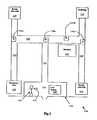
- FIG. 3is a diagrammatical representation of a portion of a healthcare facility illustrating an ambulatory navigation system of the present invention
- FIG. 4Ais a front view of a visitor key card of the present invention.
- FIG. 4Bis a rear view of the visitor key card of FIG. 2A;
- FIG. 4Cis a rear view of a second embodiment of a visitor key card of the present invention.
- FIG. 5is a front perspective view of a core station of the ambulatory navigation system of the present invention.
- FIG. 6is a front perspective view of a navigation station
- FIG. 7is a flow chart illustrating steps performed by a navigation station during a direction sequence
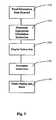
- FIG. 8is a flow chart illustrating the destination instruction logic executed by a navigation station
- FIG. 9is a block diagram illustrating another embodiment of the present invention which uses an identification number and a database which interfaces with a communication member to provide navigation instructions to a selected destination;
- FIG. 10is a block diagram illustrating yet another embodiment of the present invention which includes a badge which transmits an identification signal to a detector of a navigation station, the navigation station being coupled to a database.
- FIGS. 1 and 2illustrate components of an ambulatory navigation system of the present invention configured to provide directions to a selected destination to a pedestrian.
- FIG. 1illustrates a first station or core station 10
- FIG. 2illustrates a second station or a navigation station 12 of the present invention.
- each core station 10includes a processor 14 and an input device 16 coupled to the processor 14 .
- the input device 16is illustratively any type of input device such as a key board, key pad, mouse, touch screen, voice recognition, or other data recognition device.
- An operatoruses the input device 16 to select a desired destination for the operator or another person.
- Core station 10further includes a display 18 and a speaker 20 coupled to the processor.
- processor 14displays a menu of destination options on display 18 for the user to select using the input device 16 .
- Processor 14is coupled to a memory 22 which stores information related to a plurality of destinations.
- processor 14 of core station 10may be coupled to a communication network 24 , if desired.
- Network 24is used to permit core station 10 to access other databases for information related to destinations which may be selected.
- Network 24can also be used to update memory 22 with possible destinations to select.
- the core station 10is configured to generate an information carrying member 26 which has information related to or identifying the selected destination of the user.
- the core station 10includes an output device 28 configured to provide the information carrying member 26 with the specific information identifying the selected destination.
- the output device 28is a magnetic stripe encoder.
- the output device 28is a bar code encoder.
- the output device 28is a smart card encoder. It is understood that the output device may be any type of device for placing information on or in the information carrying member 26 .
- an attendant specifically stationed at a locationsuch as a main entrance of a facility, communicates to the person and asks the desired destination.
- the attendantthen either produces the information carrying member 26 based on the selected destination or retrieves a pre-made information carrying member 26 which includes information related to the selected destination.
- each navigation station 12includes a processor 30 and a detector or input device 32 coupled to the processor 30 .
- the detector 32configured to identify the information on or in the information carrying member 26 .
- the processor 30uses the detected information to identify the selected destination either directly, or using information stored in memory 34 coupled to processor 30 or information obtained over a communication network 24 from a remote location.
- processor 30determines directions to the selected destination from the location of the particular navigation station 12 or directions to another navigation station 12 closer to the selected destination.
- the navigation station 12then provides the person with directions to the selected destination or another navigation station 12 using either display 36 , speaker 38 , or printer 40 coupled to processor 30 .
- the processor 30also identifies the selected destination on the display 36 , speaker 38 or printer 40 so that the person can make sure that the directions are to the selected destination.
- the navigation system of the present inventiondoes not rely upon the person to manually re-enter the selected destination at each navigation station 12 .
- the navigation stations 12automatically identify the information related to the selected destination and then provide the person with directions as discussed above.
- the input device or detector 32is a magnetic stripe reader, a bar code reader, a smart card reader, a receiver, or other detector which automatically detects information on the information carrying member 26 .
- the ambulatory navigation system 100guides a person through a facility by providing updated destination instructions at prominent locations within the facility.
- Ambulatory navigation system 100is illustratively incorporated into a facility 102 such as a healthcare facility, airport, professional office building, college campus, shopping center, or the like.
- the system 100can also be used outdoors with core stations and navigation stations located at selected places within the city.
- healthcare facility 102includes a main entrance area 104 connected to a hallway 106 .
- Hallway 106intersects a second hallway 108 .
- Hallway 108includes an access area to a bank of elevators 122 and intersects additional hallways 110 , 112 .
- the healthcare facility shown in FIG. 1further includes a first ward of rooms 114 which are numbered between 1000 to 3000, a radiology department 116 , a second ward of rooms 118 which are numbered between 3001 to 6000, and an Emergency Care Unit 120 .
- Ambulatory navigation system 100illustratively includes an information carrying member 26 such as a set of key cards 126 , at least one core station 128 , and a plurality of navigation stations 130 .
- an information carrying member 26such as a set of key cards 126 , at least one core station 128 , and a plurality of navigation stations 130 .
- a visitor 124enters main entrance area 104 of healthcare facility 102 with the purpose of proceeding to a specific destination, such as a patient room to visit a family member. Visitor 124 is issued a key card 126 or other information carrying member 26 discussed above at main entrance 104 .
- the key card 126includes an information carrying member 133 containing information about the specific destination in the facility 102 of visitor 124 .
- key card 126interacts with navigation stations 130 a - 130 d to provide visitor 124 with appropriate destination instructions to the specific destination of visitor 124 .
- Key card 126illustratively includes a body member 132 which is made from an inexpensive material, such as plastic. Key card 126 is similar to room access key cards currently used by hotels. Body member 132 includes a designated area 134 which is a location to provide information, such as emergency phone numbers, or advertising. The ability to place advertisements on key card 126 reduces the costs to the facility associated with the implementation and maintenance of ambulatory navigation system 100 . Any conventional methods can be used to place information or advertising within area 134 of key card 126 , such as conventional printing or the application of labels or stickers. In one embodiment, advertising and information is embossed within area 134 on key card 126 .
- FIG. 4Bshows one embodiment of the rear side of key card 126 .
- the information carrying member 133 of key card 126is a magnetic strip 136 which stores information.
- Magnetic stripe 136is illustratively programmed by core station 128 to include a destination code corresponding to the final destination of visitor 124 as discussed above in reference to FIG. 1 .
- magnetic stripe 136is read by an associated magnetic strip reader located on navigation stations 130 to communicate to navigation station 130 the destination code stored on magnetic strip 136 as discussed above in reference to FIG. 2 .
- FIG. 4Cshows a second embodiment of the rear side of key card 126 .
- the information carrying member 133 of key card 126is a bar code region 138 which contains a series of spaced dark bars.
- the destination codeis illustratively determined by the width and spacing between the individual dark bars.
- Bar code region 138is read by a bar code reader, such as an optical scanner, located on each navigation station 130 to communicate to navigation station 130 the destination code referenced by bar code region 138 .
- bar code region 138contains the destination code, itself.
- bar code region 138is associated with a destination code stored on the system 100 . As such, by reading bar code region 138 , navigation station 130 is provided a pointer to query system 100 for the associated destination code.
- the information carrying member 133 of key card 126is any system that which is capable of communicating information to navigation station 130 . Examples include, re-radiating devices which emit a signal when queried by an interrogation signal or punched cards. Information carrying member 133 is also contemplated to be an active system, such as a battery powered transmitter, which emits a coded signal that is detected by navigation station 130 . In another embodiment, the information is a location number which is manually entered by the visitor into navigation station 130 .
- a double-sided key card 126includes information carrying members 133 on both the front and rear sides of key card 126 .
- the information carrying member 133 on the rear of key card 126illustratively includes a destination code associated with the specific destination of visitor 124 .
- the information carrying member 133 on the front of key card 126includes a destination code associated with main entrance 104 of healthcare facility 102 . As such, the front of key card 126 is used to navigate the visitor 124 from his specific destination back to main entrance 104 .
- visitor 124is issued two individual key cards 126 at main entrance 104 , each key card 126 containing one information carrying member 133 .
- the first key card 126is used to guide visitor 124 from main entrance 104 to his specific destination, and the second key card 126 is used to guide visitor 124 from his specific destination back to main entrance 104 .
- navigation stations 130include the capability of providing appropriate destination instructions to main entrance 104 by the activation of a return function, such as by depressing a button located on navigation station 130 for directions back to the main entrance.
- a return functionsuch as by depressing a button located on navigation station 130 for directions back to the main entrance.
- the navigation station 130automatically provides the appropriate destination instructions to proceed to main entrance 104 .
- a core station 128may be placed at all primary entrances and busy junctions, such as gift shops, cafeterias, and the like within the facility.
- Core station 128is a programming unit which programs key card 126 or other information carrying member 26 as discussed above.
- the core station 128is operated either by facility personnel or by visitor 124 .
- Core station 128includes a directory member 143 , either computer-based or push button selection member 144 , which allows for the selection of a destination within the facility.
- the directoryis connected to a database which provides a listing of the various destinations within the facility.
- the databaseis either locally stored in a memory of core station 128 or is retained on the facility network and accessed by core station 128 .
- core station 128includes a housing 140 which contains an information output device 141 .
- core station 128includes a display 146 , a name plate 148 and a speaker 150 .
- information output device 141is illustratively a key card slot 142 which interacts with the magnetic stripe 136 on key card 126 . If the information carrying member 133 of key card 126 is not magnetic strip 136 then key card slot 142 is replaced with the appropriate output device such as discussed above with reference to FIG. 1 . For instance if key card 126 includes bar code region 138 then output device is a bar code encoder and printer.
- the specific destination of visitor 124is selected by using push button member 144 .
- key card 126is passed through key card slot 142 .
- core station 128encodes the magnetic stripe 136 on key card 126 with a code that relates to the specific destination of visitor 124 .
- Methods for encoding the key card 126are well known in the art.
- the destination selected and programmedis displayed on display 146 as a method of verifying that an error was not made. Also, the first set of appropriate destination instructions are shown on display 146 to provide visitor 124 with initial directions to his specific destination.
- information carrying member 133is programmed to include a language indicator along with the specific destination code.
- the language indicatorindicates to navigation station 130 , in what language the appropriate destination instructions are to be provided to the person.
- ambulatory navigation system 100provides the flexibility needed for facilities 102 located in regions with diverse populations.
- Navigation station 130is placed at intersection points or other location within the facility.
- An intersection pointis a location within facility 102 where the visitor 124 is required to make a choice on which direction to proceed.
- navigation station 130 ais placed at the intersection of hallway 106 and hallway 108 ;
- navigation station 130 bis placed at the intersection of hallway 108 and hallway 110 ;
- navigation station 130 cis placed at the intersection of hallway 108 and hallway 112 ;
- navigation station 130 dis placed at the bank of elevators 122 .
- Navigation station 130 of FIG. 6includes a housing 152 , a information reading member 153 , a display 156 , a name plate 158 and a speaker 160 .
- Information reading member 153is illustratively a key card slot 154 which interacts with magnetic stripe 136 on key card 126 . If the information carrying member 133 of key card 126 is not magnetic stripe 136 then key card slot 154 is replaced with the appropriate information reading member 153 , input device or detector 32 as discussed above in reference to FIG. 2 . For instance if key card 126 includes bar code region 138 then information reading member 153 is a bar code reader such as an optical scanner.
- Navigation station 130operates in the following way. Visitor 124 upon approaching a navigation station 130 passes key card 126 through key card slot 154 . Navigation station 130 reads the specific destination code stored on magnetic strip 136 of key card 126 . Based upon the specific destination code, navigation station 130 provides visitor 124 with appropriate destination instructions. The appropriate destination instructions are provided either visually on display 156 or audibly through annunciator 160 or a combination of both. The instructions may also be printed.
- Navigation station 130acquires the information contained on information carrying member 133 of key card 126 , as represented by block 170 .
- Station 130determines the appropriate destination instruction 155 to give to visitor 124 , as represented by block 172 .
- Navigation station 130displays the appropriate destination instruction 155 as represented by block 174 .
- navigation station 130in one embodiment, audibly emits the appropriate destination instruction 155 , as represented by block 176 .
- navigation station 130erases display 156 , resets and waits for the next key card 126 to be passed through slot 154 .
- the level of detail included in appropriate destination instruction 155 by navigation station 130varies depending on the proximity of visitor 124 to his specific destination. For example, more detailed instructions are given the closer visitor 124 is to his specific destination. An example detailed instruction is, “Room 2571 is down the hallway to the left and is the fifth door on the right-hand side of the hallway.” A more general instruction is given by navigation station 130 when visitor 124 is further from his specific destination, such as, “Take the hallway to the right, go the elevators on the left hand side and proceed to third floor.”
- navigation station 130provides visitor 124 with all the instructions required to navigate from navigation station 130 to the specific destination of visitor 124 . As such, visitor 124 needs only to stop at a future navigation station 130 if he forgets the last set of appropriate destination instructions.
- appropriate destination instruction 155does not take visitor 124 to his specific destination, the instruction does take visitor 124 to the next navigation station 130 .
- visitor 124leaves core station 128 and approaches navigation station 130 a at the intersection of hallway 106 and hallway 108 .
- navigation station 130 aprovides visitor 124 with the following appropriate destination instruction 155 , “Turn to the left and proceed to the navigation station located at the T in the hallway.”
- the appropriate destination instruction 155could include the name of the next navigation station in the instruction.
- the appropriate destination instruction 155might be, “Turn to the left and proceed to the navigation station 130 c”.
- FIG. 8an embodiment of the appropriate destination instruction logic 200 used by the processor 30 within navigation station 130 is shown.
- visitor 124proceeds down hallway 106 with key card 126 to navigation station 130 a .
- visitor 124passes key card 126 through key card slot 154 a .
- Appropriate destination instruction logic 200based on the location of navigation station 130 , provides a manageable method of determining the appropriate destination instruction 155 to display.
- the logic 200 provided in FIG. 8is tailored to the location of navigation station 130 a within facility 102 in FIG. 3 and with the assumption that the destination code stored in information carrying member 133 corresponds to a patient room number. As such, FIG. 8, is only an example of logic 200 .
- the first step of logic 200is to determine whether the room number programmed on key card 126 is greater than 6000. If the room number is greater than 6000 the appropriate destination instruction 155 displayed by navigation station 130 a is, “Take the corridor to the right to the bank of elevators on the right and proceed to the second floor.” If the room number is not greater than 6000, logic 200 determines if the room number is less than or equal to 3001, as represented by block 206 .
- the appropriate destination instruction 155displayed by navigation station 130 a is, “Take the corridor to the right and proceed to navigation station 130 b .” If the room number is greater than or equal to 3001, then the appropriate destination instruction 155 displayed by navigation station 130 A, as represented by block 210 , is, “Take the corridor to the left and proceed to navigation station 130 c ”. Assuming visitor 124 is proceeding to patient room 4002, the logic 200 would display the instructions provided in block 210 because room number 4002 is less than 6000 and greater than 3001.
- navigation station 130may include a button 159 or other member for activating navigation station 130 such that navigation station 130 provides appropriate destination instructions 155 on how to return to main entrance 104 .
- navigation station 130 and core station 128provide a call system and each includes a speaker 160 , a microphone, and a call button.
- navigation stations 130 and core station 128would operate as a call system to allow visitors 124 to call core station 128 to ask facility personnel for additional instructions.
- navigation station 130 and core station 128are integrated into a caregiver locating and tracking system, such that the last known location of visitor 124 is ascertainable in case of emergency or such that traffic patterns of visitors are determined for analysis.
- the information carrying member 230provides identification information such as an identification number or other unique identification signal, pattern or the like corresponding to the person seeking directions.
- the information carrying member 230is illustratively a magnetic card, a bar-coded card, a RFID coil, an IR or RF emitting badge, a fingerprint, a retina, or the like.
- the navigation station 232 in the FIG. 9 embodimentillustratively includes an identification device 234 , a processor 236 coupled to a memory 237 , and a communication member 238 .
- the identification device 234corresponds to the particular type of information carrying member 230 used with the navigation system 220 .
- identification device 234is a magnetic card reader, a bar code reader, a RF source and receiver, an IR or RF receiver, the fingerprint reader, a retina scanner, or the like.
- the identification device 234detects the identification information from information carrying member 230 and supplies the information to processor 236 .
- Processor 236is coupled to a database 240 by a wired or wireless communication network 242 .
- database 240includes destination information corresponding to the identification information detected by identification device 234 .
- an information carrying member 230is provided to the person which provides unique identification information for the person as discussed above. Additional information related to the person is obtained and entered into the database by an operator using an input device 244 such as a keyboard, mouse, touch screen display, voice recognition device, or other type of input device. The operator also inputs information in the database 240 related to the selected destination of the person. Database 240 may also include navigation instructions from different navigation stations to selected destinations. The operator may also input the name of the person or certain conditions such as handicaps of the person into the database 240 .
- the identification information on the information carrying member 230is correlated to the information input in the database 240 related to the particular person.
- processor 236accesses database 240 to determine the selected destination corresponding to the specific identification information detected from the information carrying member 230 of the particular person. Once the destination information is obtained from database 240 , processor 236 can obtain navigation instructions from database 240 or can use navigation instructions stored in memory 237 of navigation station 232 . Navigation instructions from the navigation station 232 to the selected destination are then provided to the person using communication member 238 .
- the navigation instructionscan be personalized using the person's name identified from database 240 so that the person knows that the instructions provided by the communication member 238 are for him or her.
- instructionscan be customized based on additional conditions of the person stored in database 240 such as handicaps of the person. For instance, references to color can be omitted if the person is color blind. If the person is mentally or otherwise debilitated and at an unexpected location, the system 220 can alert security to provide assistance.
- the communication member 238may be a speaker, display, or printer as discussed above. In this embodiment, and the other illustrated embodiments of the present invention, the communication member need not be physically “coupled” to the processor. There may be multiple communication members activated by the processor or even subprocessors. For instance, a series of lights may illustratively be installed on every walkway, hallway, step, door of a facility, seat of a sports stadium or the like. When a person enters with the information carrying member, the lights are lit in a way to guide him to the appropriate location, room, seat, or the like. Alternatively, the lights on the correct door or seat may flash to provide an indication to the person.
- the communication membermay be a portable device such as a PalmPilot type device that the navigator carries with him. Therefore, it is understood that the communication member is not be restricted to a display, a speaker, or a printer.
- the communication memberis anything that communicates, whether it is permanently sited or portable, whether it is sight, sound, or feel.
- database 240provides flexibility for the navigation system 220 . For example, if a person must go to a second location, the prior location listed in the database 240 is simply replaced with the new location without the requirement for adjusting the information carrying member 230 .
- the navigation systemis integrated with a conventional personnel and asset locating and tracking system such as the COMposer® system or COMLINXTM system available from Hill-Rom NetLinx located in Cary, N.C. See also U.S. Pat. Nos. 5,561,412; 5,699,038; and 5,838,223 which are incorporated herein by reference.
- an attendant at a main entrance of a facility or other desired locationinputs information related to the person into the locating and tracking system database 256 and then provides the person with a badge 252 which transmits an identification signal including identification information identifying the person and/or a selected destination for the person.
- the badge 252uses an infrared, radio frequency, ultrasonic, or other type of transmitter which periodically transmits signals from the badge.
- Receivers throughout the facility and on the navigation stationsdetect the identification information. Therefore, the locating and tracking system tracks movement of the person through the facility and the navigation stations provide directions to the person.
- An indicator signalmay be sent to a receiver on the badge if the patient does not follow directions and is headed in the wrong direction away from the selected destination.
- the attendant at the main entrance or other desired location facilityprovides the person with a transmitter 250 such as an IR, RF, ultrasonic, or other type of transmitter which periodically transmits a unique identification data signal.
- the transmitter 250is located on a tag or badge 252 designed to be worn by the person entering the facility.
- the attendantuses an input device 254 such as a master station of a locating and tracking system to input information related to the person, the selected destination, as well as any other desired information regarding the person such as conditions, handicaps, or the like into a database 256 .
- Information in the database 256is correlated to the identification information transmitted by transmitter 250 .
- a receiver 260 of navigation station 258detects the identification signal from transmitter 250 in a conventional manner.
- Receiver 260is coupled to a processor 262 of navigation station 258 .
- Processor 262accesses the database 256 using a wired or wireless communication network 264 . Based on the identification information obtained from the signal, processor 262 obtains corresponding destination information as well as information related to the person such as name, handicaps, or the like from the database 256 .
- Processor 260then obtains navigation instructions based on the identified destination either from memory 266 of navigation station 258 or from navigation instructions stored in database 256 .
- Processor 260then communicates the instructions to the person using communication member 268 .
- Processor 262also updates the database 256 with the actual location of the person in the facility.
- Conventional locating and tracking system receivers 269 located throughout the facilityalso detect the identification signal from transmitter 250 .
- Receivers 269are coupled to input device 254 to update actual location information related to the person stored in database 256 . Therefore, the locating and tracking system tracks the actual location of the person in the facility.
- the location informationcan be updated in database 256 without changing the identification signal from transmitter 250 .
- the attendant or operatorcan also enter a plurality of destinations for the person in database 256 . For instance, if a person desires to visit a specific room in a hospital, that room can be entered as the first selected destination.
- the second selected destinationmay be, for instance, the cafeteria, the main entrance of the facility or other location. As a patient moves from the main entrance toward the desired room, directions are given at each navigation station 258 toward the room.
- the attendantmay program the transmitter with a unique identification signal corresponding to the selected destination.
- the navigation station 258includes a transmitter 270 and the badge 252 includes a receiver 272 .
- Processor 262provides a wireless signal 273 from transmitter 270 to receiver 272 .
- Receiver 272is coupled to display 274 on badge 252 .
- Display 274may be a indicator light, LCD display, or other type of display screen.
- a speaker 276may be provided on badge 252 . Therefore, the navigation instructions or other information may be transmitted directly to the display 274 or speaker 276 of badge 252 .
- the locating and tracking systemtracks movement of the patient through the facility and the navigation stations 258 provide directions to the person.
- the indicator signal 273can be provided from transmitter 270 to badge 252 if the locating and tracking system determines that a person has not followed the directions given to the person and is located at an unexpected location.
- a signal or instructionscan also be provided to the person using a transmitter located at the master station or using conventional paging or messaging techniques.
Landscapes
- Engineering & Computer Science (AREA)
- Radar, Positioning & Navigation (AREA)
- Remote Sensing (AREA)
- Physics & Mathematics (AREA)
- General Physics & Mathematics (AREA)
- Automation & Control Theory (AREA)
- Navigation (AREA)
- Traffic Control Systems (AREA)
Abstract
Description
Claims (71)
Priority Applications (7)
| Application Number | Priority Date | Filing Date | Title |
|---|---|---|---|
| US09/798,398US6622088B2 (en) | 2001-03-02 | 2001-03-02 | Ambulatory navigation system |
| PCT/US2002/002875WO2002070992A2 (en) | 2001-03-02 | 2002-01-31 | Ambulatory navigation system |
| CA002438183ACA2438183A1 (en) | 2001-03-02 | 2002-01-31 | Ambulatory navigation system |
| JP2002569668AJP2004530866A (en) | 2001-03-02 | 2002-01-31 | Pedestrian navigation system |
| AU2002242045AAU2002242045A1 (en) | 2001-03-02 | 2002-01-31 | Ambulatory navigation system |
| EP02707649AEP1364185A2 (en) | 2001-03-02 | 2002-01-31 | Ambulatory navigation system |
| US10/637,392US20040034466A1 (en) | 2001-03-02 | 2003-08-08 | Ambulatory navigation system |
Applications Claiming Priority (1)
| Application Number | Priority Date | Filing Date | Title |
|---|---|---|---|
| US09/798,398US6622088B2 (en) | 2001-03-02 | 2001-03-02 | Ambulatory navigation system |
Related Child Applications (1)
| Application Number | Title | Priority Date | Filing Date |
|---|---|---|---|
| US10/637,392DivisionUS20040034466A1 (en) | 2001-03-02 | 2003-08-08 | Ambulatory navigation system |
Publications (2)
| Publication Number | Publication Date |
|---|---|
| US20020123843A1 US20020123843A1 (en) | 2002-09-05 |
| US6622088B2true US6622088B2 (en) | 2003-09-16 |
Family
ID=25173299
Family Applications (2)
| Application Number | Title | Priority Date | Filing Date |
|---|---|---|---|
| US09/798,398Expired - LifetimeUS6622088B2 (en) | 2001-03-02 | 2001-03-02 | Ambulatory navigation system |
| US10/637,392AbandonedUS20040034466A1 (en) | 2001-03-02 | 2003-08-08 | Ambulatory navigation system |
Family Applications After (1)
| Application Number | Title | Priority Date | Filing Date |
|---|---|---|---|
| US10/637,392AbandonedUS20040034466A1 (en) | 2001-03-02 | 2003-08-08 | Ambulatory navigation system |
Country Status (6)
| Country | Link |
|---|---|
| US (2) | US6622088B2 (en) |
| EP (1) | EP1364185A2 (en) |
| JP (1) | JP2004530866A (en) |
| AU (1) | AU2002242045A1 (en) |
| CA (1) | CA2438183A1 (en) |
| WO (1) | WO2002070992A2 (en) |
Cited By (37)
| Publication number | Priority date | Publication date | Assignee | Title |
|---|---|---|---|---|
| US20030080901A1 (en)* | 2001-10-25 | 2003-05-01 | Koninklijke Philips Electronics N.V. | RFID navigation system |
| US6924741B2 (en)* | 2002-09-18 | 2005-08-02 | Hitachi, Ltd. | Method and system for displaying guidance information |
| US20060129308A1 (en)* | 2004-12-10 | 2006-06-15 | Lawrence Kates | Management and navigation system for the blind |
| US20060247849A1 (en)* | 2005-04-27 | 2006-11-02 | Proxemics, Inc. | Wayfinding |
| US20060293794A1 (en)* | 2005-06-28 | 2006-12-28 | Harwig Jeffrey L | RFID navigational system for robotic floor treater |
| US20070030152A1 (en)* | 2005-08-08 | 2007-02-08 | Xerox Corporation | Direction signage system |
| US20070139190A1 (en)* | 2005-12-15 | 2007-06-21 | Kimberly-Clark Worldwide, Inc. | System and method that provide emergency instructions |
| US20070225911A1 (en)* | 2006-03-23 | 2007-09-27 | Rich Chanick | User positional and venue information integration system and method |
| US20070257984A1 (en)* | 2004-08-10 | 2007-11-08 | Thomas Krobath | Method for Displaying Route Information |
| US7319386B2 (en) | 2004-08-02 | 2008-01-15 | Hill-Rom Services, Inc. | Configurable system for alerting caregivers |
| US20080180218A1 (en)* | 2006-11-07 | 2008-07-31 | Flax Stephen W | Bi-Modal Remote Identification System |
| US20090112461A1 (en)* | 2007-10-31 | 2009-04-30 | John Murphy | Mapping system and method |
| US20100131183A1 (en)* | 2001-04-09 | 2010-05-27 | Carlos Antonio Gallo Garavano | System for finding vehicles parked inside buildings and roofed surfaces |
| US20100158328A1 (en)* | 2008-12-19 | 2010-06-24 | Wistron Corporation | Fingerprint-initiated navigating method, method for linking a fingerprint and a navigation destination, and navigating device |
| US20100176941A1 (en)* | 2009-01-12 | 2010-07-15 | Rachit Jain | Method and system for facilitating automated navigation in a healthcare environment |
| US7761226B1 (en) | 2005-07-27 | 2010-07-20 | The United States Of America As Represented By The Secretary Of The Navy | Interactive pedestrian routing system |
| US7837958B2 (en) | 2004-11-23 | 2010-11-23 | S.C. Johnson & Son, Inc. | Device and methods of providing air purification in combination with superficial floor cleaning |
| US7852208B2 (en) | 2004-08-02 | 2010-12-14 | Hill-Rom Services, Inc. | Wireless bed connectivity |
| US7868740B2 (en) | 2007-08-29 | 2011-01-11 | Hill-Rom Services, Inc. | Association of support surfaces and beds |
| US20110074585A1 (en)* | 2009-09-28 | 2011-03-31 | Augusta E.N.T., P.C. | Patient tracking system |
| US8046625B2 (en) | 2008-02-22 | 2011-10-25 | Hill-Rom Services, Inc. | Distributed fault tolerant architecture for a healthcare communication system |
| US8272892B2 (en) | 2003-08-21 | 2012-09-25 | Hill-Rom Services, Inc. | Hospital bed having wireless data capability |
| EP2581109A1 (en) | 2004-07-28 | 2013-04-17 | Cyberonics, Inc. | Power supply monitoring for an implantable device |
| US8461968B2 (en) | 2007-08-29 | 2013-06-11 | Hill-Rom Services, Inc. | Mattress for a hospital bed for use in a healthcare facility and management of same |
| US8774970B2 (en) | 2009-06-11 | 2014-07-08 | S.C. Johnson & Son, Inc. | Trainable multi-mode floor cleaning device |
| US8779924B2 (en) | 2010-02-19 | 2014-07-15 | Hill-Rom Services, Inc. | Nurse call system with additional status board |
| US9411934B2 (en) | 2012-05-08 | 2016-08-09 | Hill-Rom Services, Inc. | In-room alarm configuration of nurse call system |
| US9734293B2 (en) | 2007-10-26 | 2017-08-15 | Hill-Rom Services, Inc. | System and method for association of patient care devices to a patient |
| US9830424B2 (en) | 2013-09-18 | 2017-11-28 | Hill-Rom Services, Inc. | Bed/room/patient association systems and methods |
| US10136815B2 (en) | 2012-09-24 | 2018-11-27 | Physio-Control, Inc. | Patient monitoring device with remote alert |
| US10276029B2 (en) | 2014-11-13 | 2019-04-30 | Gojo Industries, Inc. | Methods and systems for obtaining more accurate compliance metrics |
| US10636321B2 (en) | 2014-07-02 | 2020-04-28 | Gojo Industries, Inc. | Methods and systems for improving hand hygiene |
| US11504061B2 (en) | 2017-03-21 | 2022-11-22 | Stryker Corporation | Systems and methods for ambient energy powered physiological parameter monitoring |
| US11911325B2 (en) | 2019-02-26 | 2024-02-27 | Hill-Rom Services, Inc. | Bed interface for manual location |
| US12186241B2 (en) | 2021-01-22 | 2025-01-07 | Hill-Rom Services, Inc. | Time-based wireless pairing between a medical device and a wall unit |
| US12251243B2 (en) | 2008-02-22 | 2025-03-18 | Hill-Rom Services, Inc. | Distributed healthcare communication system |
| US12279999B2 (en) | 2021-01-22 | 2025-04-22 | Hill-Rom Services, Inc. | Wireless configuration and authorization of a wall unit that pairs with a medical device |
Families Citing this family (33)
| Publication number | Priority date | Publication date | Assignee | Title |
|---|---|---|---|---|
| FR2839805A1 (en)* | 2002-05-17 | 2003-11-21 | Florence Daumas | Speech synthesising transport information unit includes microphone and voice recognition unit linked to algorithm providing itinerary information |
| JP3909300B2 (en)* | 2003-04-18 | 2007-04-25 | 有限会社ミキシィ | Automatic traveling wheelchair, wheelchair automatic traveling system, and wheelchair automatic traveling method |
| JP4053462B2 (en)* | 2003-05-22 | 2008-02-27 | 株式会社日立製作所 | Guidance information providing system |
| US6992574B2 (en)* | 2003-07-02 | 2006-01-31 | International Business Machines Corporation | Object matching via RFID |
| FR2874444A1 (en)* | 2004-12-03 | 2006-02-24 | France Telecom | Mobile terminal detection and guiding method e.g. mobile telephone, for use by organization, involves repeating mobile terminal detection and signaling unit activation till detection by guiding terminal corresponding to end of itinerary |
| CA2550812A1 (en)* | 2005-06-22 | 2006-12-22 | Axigon Healthcare Technologies Incorporated | Two-way wireless monitoring system and method |
| WO2007004193A1 (en)* | 2005-07-05 | 2007-01-11 | Koninklijke Philips Electronics N.V. | Communication system and method |
| US20070171049A1 (en)* | 2005-07-15 | 2007-07-26 | Argasinski Henry E | Emergency response imaging system and method |
| FR2901872A1 (en)* | 2006-05-31 | 2007-12-07 | Florence Daumas | Portable device for vocally delivering underground route to e.g. blind person, has vocal communication device providing information via loud speaker or earphone, where sound volume of loud speaker or earphone is adjusted using potentiometer |
| US20080068165A1 (en)* | 2006-09-12 | 2008-03-20 | Dewitt Jimmie Earl | Radio frequency identification numbering for correct direction indication |
| US8768720B2 (en)* | 2007-04-12 | 2014-07-01 | Epic Systems Corporation | Location limited check-in kiosk method and apparatus |
| US20090112473A1 (en)* | 2007-10-31 | 2009-04-30 | Hung Sung Lu | Method for providing location and promotional information associated with a building complex |
| US20090187337A1 (en)* | 2007-12-19 | 2009-07-23 | Denk Jr William E | System and method for navigation of a building, campus or retail structure with a mobile device |
| DE102008053149A1 (en)* | 2008-10-24 | 2010-05-12 | Rohde & Schwarz Gmbh & Co. Kg | Navigation method for use in navigation device and local information sensor of navigation system for navigation in unfamiliar areas, involves transmitting data of local information sensors from local information sensors at navigation device |
| GB2484765A (en)* | 2010-05-19 | 2012-04-25 | Arinc Inc | Airport navigation display unit using a boarding pass barcode scanner |
| US8849560B2 (en) | 2010-05-19 | 2014-09-30 | Arinc Incorporated | Method and apparatus for customer/passenger wayfinding using boarding pass barcode scanning capabilities on low-cost display devices |
| US9985942B2 (en)* | 2012-07-30 | 2018-05-29 | Weckey | Portable sign-in service |
| DE102014206422A1 (en)* | 2014-04-03 | 2015-10-08 | Siemens Aktiengesellschaft | Wayfinding system and method for pathfinding |
| US9212924B1 (en)* | 2014-08-21 | 2015-12-15 | Microsoft Technology Licensing, Llc | Multimode transportation transitions |
| US10677484B2 (en) | 2015-05-04 | 2020-06-09 | Johnson Controls Technology Company | User control device and multi-function home control system |
| AU2016257459B2 (en) | 2015-05-04 | 2019-04-04 | Johnson Controls Technology Company | Multi-function home control system with control system hub and remote sensors |
| JP6543515B2 (en)* | 2015-06-11 | 2019-07-10 | 大日本印刷株式会社 | Guidance information display device, guidance information display system, and program |
| US10410300B2 (en) | 2015-09-11 | 2019-09-10 | Johnson Controls Technology Company | Thermostat with occupancy detection based on social media event data |
| US10760809B2 (en) | 2015-09-11 | 2020-09-01 | Johnson Controls Technology Company | Thermostat with mode settings for multiple zones |
| US10546472B2 (en) | 2015-10-28 | 2020-01-28 | Johnson Controls Technology Company | Thermostat with direction handoff features |
| US10187471B2 (en) | 2016-10-28 | 2019-01-22 | Johnson Controls Technology Company | Thermostat with direction display |
| US10345781B2 (en) | 2015-10-28 | 2019-07-09 | Johnson Controls Technology Company | Multi-function thermostat with health monitoring features |
| US10020956B2 (en)* | 2016-10-28 | 2018-07-10 | Johnson Controls Technology Company | Thermostat with direction handoff features |
| US10655881B2 (en) | 2015-10-28 | 2020-05-19 | Johnson Controls Technology Company | Thermostat with halo light system and emergency directions |
| US10430567B2 (en) | 2017-01-18 | 2019-10-01 | International Business Machines Corporation | Customizable firmware based on access attributes |
| US11162698B2 (en) | 2017-04-14 | 2021-11-02 | Johnson Controls Tyco IP Holdings LLP | Thermostat with exhaust fan control for air quality and humidity control |
| CN108303076A (en)* | 2018-01-09 | 2018-07-20 | 四川西谷物联科技有限公司 | Air navigation aid, device and electronic equipment |
| US11107390B2 (en) | 2018-12-21 | 2021-08-31 | Johnson Controls Technology Company | Display device with halo |
Citations (30)
| Publication number | Priority date | Publication date | Assignee | Title |
|---|---|---|---|---|
| WO1982002271A1 (en) | 1980-12-29 | 1982-07-08 | Rudolph Jan Smedema | Route-indicating system |
| US4709330A (en) | 1983-10-07 | 1987-11-24 | Ngk Insulators Ltd. | System for supervising and guiding persons in construction |
| US4817043A (en) | 1988-06-28 | 1989-03-28 | Brown Johnny M | Information kiosk |
| US4935907A (en) | 1988-02-22 | 1990-06-19 | Friedman Mark B | Electronic homing system |
| US4974170A (en) | 1988-01-21 | 1990-11-27 | Directional Data, Inc. | Electronic directory for identifying a selected group of subscribers |
| US4991126A (en) | 1986-05-14 | 1991-02-05 | Lothar Reiter | Electronic-automatic orientation device for walkers and the blind |
| US5062151A (en) | 1983-01-13 | 1991-10-29 | Fisher Berkeley Corporation | Communication system |
| EP0578374A1 (en) | 1992-06-29 | 1994-01-12 | Nortel Networks Corporation | Method and apparatus for providing a personal locator, access control and asset tracking service using an in-building telephone network |
| US5289572A (en) | 1989-10-24 | 1994-02-22 | Mitsubishi Denki Kabushiki Kaisha | Electronic map combined with user service information |
| US5337046A (en) | 1990-02-23 | 1994-08-09 | Finance Techniques Et Systemes | System for communication between pedestrians and vehicles |
| US5438321A (en) | 1991-10-11 | 1995-08-01 | Bernard; Hermanus A. | Location system |
| US5470233A (en) | 1994-03-17 | 1995-11-28 | Arkenstone, Inc. | System and method for tracking a pedestrian |
| EP0726447A1 (en)* | 1995-02-09 | 1996-08-14 | Zexel Corporation | Incremental route calculation |
| US5559707A (en) | 1994-06-24 | 1996-09-24 | Delorme Publishing Company | Computer aided routing system |
| US5561412A (en) | 1993-07-12 | 1996-10-01 | Hill-Rom, Inc. | Patient/nurse call system |
| US5629981A (en) | 1994-07-29 | 1997-05-13 | Texas Instruments Incorporated | Information management and security system |
| US5635907A (en) | 1993-08-10 | 1997-06-03 | Bernard; Hermanus A. | Location system |
| US5699038A (en) | 1993-07-12 | 1997-12-16 | Hill-Rom, Inc. | Bed status information system for hospital beds |
| US5838223A (en) | 1993-07-12 | 1998-11-17 | Hill-Rom, Inc. | Patient/nurse call system |
| US5842145A (en) | 1996-07-08 | 1998-11-24 | Zimmer; John S. | Apparatus for providing individualized maps to pedestrians |
| US5864125A (en)* | 1994-07-08 | 1999-01-26 | Szabo; Laszlo | Navigation system data entry card having imprinted pictorial and bar code navigation information |
| US5902347A (en) | 1996-11-19 | 1999-05-11 | American Navigation Systems, Inc. | Hand-held GPS-mapping device |
| US5908465A (en) | 1995-09-27 | 1999-06-01 | Aisin Aw Co., Ltd. | Navigation system for displaying a structure-shape map |
| JPH11344354A (en)* | 1998-06-03 | 1999-12-14 | Dainippon Printing Co Ltd | Destination card, travel guidance system, destination coordinate input method of travel guidance system, and destination coordinate recording method of travel guidance system |
| DE20006566U1 (en) | 2000-04-06 | 2000-08-17 | Bartelmus, Christoph, 66131 Saarbrücken | Navigation and information system based on infrared technology |
| US6119065A (en) | 1996-07-09 | 2000-09-12 | Matsushita Electric Industrial Co., Ltd. | Pedestrian information providing system, storage unit for the same, and pedestrian information processing unit |
| US6169515B1 (en)* | 1994-09-01 | 2001-01-02 | British Telecommunications Public Limited Company | Navigation information system |
| US6199010B1 (en)* | 1998-05-04 | 2001-03-06 | Lucent Technologies, Inc. | Wireless telecommunications system that provides navigational assistance to travelers |
| US6360167B1 (en)* | 1999-01-29 | 2002-03-19 | Magellan Dis, Inc. | Vehicle navigation system with location-based multi-media annotation |
| US6405126B1 (en)* | 1998-10-22 | 2002-06-11 | Trimble Navigation Limited | Pre-programmed destinations for in-vehicle navigation |
Family Cites Families (4)
| Publication number | Priority date | Publication date | Assignee | Title |
|---|---|---|---|---|
| US6321158B1 (en)* | 1994-06-24 | 2001-11-20 | Delorme Publishing Company | Integrated routing/mapping information |
| US6539393B1 (en)* | 1999-09-30 | 2003-03-25 | Hill-Rom Services, Inc. | Portable locator system |
| US6418372B1 (en)* | 1999-12-10 | 2002-07-09 | Siemens Technology-To-Business Center, Llc | Electronic visitor guidance system |
| US6225906B1 (en)* | 2000-03-26 | 2001-05-01 | Bernard Shore | Patient monitoring and alarm system |
- 2001
- 2001-03-02USUS09/798,398patent/US6622088B2/ennot_activeExpired - Lifetime
- 2002
- 2002-01-31WOPCT/US2002/002875patent/WO2002070992A2/ennot_activeApplication Discontinuation
- 2002-01-31JPJP2002569668Apatent/JP2004530866A/enactivePending
- 2002-01-31AUAU2002242045Apatent/AU2002242045A1/ennot_activeAbandoned
- 2002-01-31EPEP02707649Apatent/EP1364185A2/ennot_activeWithdrawn
- 2002-01-31CACA002438183Apatent/CA2438183A1/ennot_activeAbandoned
- 2003
- 2003-08-08USUS10/637,392patent/US20040034466A1/ennot_activeAbandoned
Patent Citations (30)
| Publication number | Priority date | Publication date | Assignee | Title |
|---|---|---|---|---|
| WO1982002271A1 (en) | 1980-12-29 | 1982-07-08 | Rudolph Jan Smedema | Route-indicating system |
| US5062151A (en) | 1983-01-13 | 1991-10-29 | Fisher Berkeley Corporation | Communication system |
| US4709330A (en) | 1983-10-07 | 1987-11-24 | Ngk Insulators Ltd. | System for supervising and guiding persons in construction |
| US4991126A (en) | 1986-05-14 | 1991-02-05 | Lothar Reiter | Electronic-automatic orientation device for walkers and the blind |
| US4974170A (en) | 1988-01-21 | 1990-11-27 | Directional Data, Inc. | Electronic directory for identifying a selected group of subscribers |
| US4935907A (en) | 1988-02-22 | 1990-06-19 | Friedman Mark B | Electronic homing system |
| US4817043A (en) | 1988-06-28 | 1989-03-28 | Brown Johnny M | Information kiosk |
| US5289572A (en) | 1989-10-24 | 1994-02-22 | Mitsubishi Denki Kabushiki Kaisha | Electronic map combined with user service information |
| US5337046A (en) | 1990-02-23 | 1994-08-09 | Finance Techniques Et Systemes | System for communication between pedestrians and vehicles |
| US5438321A (en) | 1991-10-11 | 1995-08-01 | Bernard; Hermanus A. | Location system |
| EP0578374A1 (en) | 1992-06-29 | 1994-01-12 | Nortel Networks Corporation | Method and apparatus for providing a personal locator, access control and asset tracking service using an in-building telephone network |
| US5561412A (en) | 1993-07-12 | 1996-10-01 | Hill-Rom, Inc. | Patient/nurse call system |
| US5699038A (en) | 1993-07-12 | 1997-12-16 | Hill-Rom, Inc. | Bed status information system for hospital beds |
| US5838223A (en) | 1993-07-12 | 1998-11-17 | Hill-Rom, Inc. | Patient/nurse call system |
| US5635907A (en) | 1993-08-10 | 1997-06-03 | Bernard; Hermanus A. | Location system |
| US5470233A (en) | 1994-03-17 | 1995-11-28 | Arkenstone, Inc. | System and method for tracking a pedestrian |
| US5559707A (en) | 1994-06-24 | 1996-09-24 | Delorme Publishing Company | Computer aided routing system |
| US5864125A (en)* | 1994-07-08 | 1999-01-26 | Szabo; Laszlo | Navigation system data entry card having imprinted pictorial and bar code navigation information |
| US5629981A (en) | 1994-07-29 | 1997-05-13 | Texas Instruments Incorporated | Information management and security system |
| US6169515B1 (en)* | 1994-09-01 | 2001-01-02 | British Telecommunications Public Limited Company | Navigation information system |
| EP0726447A1 (en)* | 1995-02-09 | 1996-08-14 | Zexel Corporation | Incremental route calculation |
| US5908465A (en) | 1995-09-27 | 1999-06-01 | Aisin Aw Co., Ltd. | Navigation system for displaying a structure-shape map |
| US5842145A (en) | 1996-07-08 | 1998-11-24 | Zimmer; John S. | Apparatus for providing individualized maps to pedestrians |
| US6119065A (en) | 1996-07-09 | 2000-09-12 | Matsushita Electric Industrial Co., Ltd. | Pedestrian information providing system, storage unit for the same, and pedestrian information processing unit |
| US5902347A (en) | 1996-11-19 | 1999-05-11 | American Navigation Systems, Inc. | Hand-held GPS-mapping device |
| US6199010B1 (en)* | 1998-05-04 | 2001-03-06 | Lucent Technologies, Inc. | Wireless telecommunications system that provides navigational assistance to travelers |
| JPH11344354A (en)* | 1998-06-03 | 1999-12-14 | Dainippon Printing Co Ltd | Destination card, travel guidance system, destination coordinate input method of travel guidance system, and destination coordinate recording method of travel guidance system |
| US6405126B1 (en)* | 1998-10-22 | 2002-06-11 | Trimble Navigation Limited | Pre-programmed destinations for in-vehicle navigation |
| US6360167B1 (en)* | 1999-01-29 | 2002-03-19 | Magellan Dis, Inc. | Vehicle navigation system with location-based multi-media annotation |
| DE20006566U1 (en) | 2000-04-06 | 2000-08-17 | Bartelmus, Christoph, 66131 Saarbrücken | Navigation and information system based on infrared technology |
Cited By (100)
| Publication number | Priority date | Publication date | Assignee | Title |
|---|---|---|---|---|
| US20100131183A1 (en)* | 2001-04-09 | 2010-05-27 | Carlos Antonio Gallo Garavano | System for finding vehicles parked inside buildings and roofed surfaces |
| US20030080901A1 (en)* | 2001-10-25 | 2003-05-01 | Koninklijke Philips Electronics N.V. | RFID navigation system |
| US6924741B2 (en)* | 2002-09-18 | 2005-08-02 | Hitachi, Ltd. | Method and system for displaying guidance information |
| US9142923B2 (en) | 2003-08-21 | 2015-09-22 | Hill-Rom Services, Inc. | Hospital bed having wireless data and locating capability |
| US9572737B2 (en) | 2003-08-21 | 2017-02-21 | Hill-Rom Services, Inc. | Hospital bed having communication modules |
| US9925104B2 (en) | 2003-08-21 | 2018-03-27 | Hill-Rom Services, Inc. | Hospital bed and room communication modules |
| US8272892B2 (en) | 2003-08-21 | 2012-09-25 | Hill-Rom Services, Inc. | Hospital bed having wireless data capability |
| US10206837B2 (en) | 2003-08-21 | 2019-02-19 | Hill-Rom Services, Inc. | Hospital bed and room communication modules |
| EP2581109A1 (en) | 2004-07-28 | 2013-04-17 | Cyberonics, Inc. | Power supply monitoring for an implantable device |
| US9861321B2 (en) | 2004-08-02 | 2018-01-09 | Hill-Rom Services, Inc. | Bed alarm communication system |
| US10278582B2 (en) | 2004-08-02 | 2019-05-07 | Hill-Rom Services, Inc. | Hospital bed having wired and wireless network connectivity |
| US8917166B2 (en) | 2004-08-02 | 2014-12-23 | Hill-Rom Services, Inc. | Hospital bed networking system and method |
| US9050031B2 (en) | 2004-08-02 | 2015-06-09 | Hill-Rom Services, Inc. | Healthcare communication system having configurable alarm rules |
| US9775519B2 (en) | 2004-08-02 | 2017-10-03 | Hill-Rom Services, Inc. | Network connectivity unit for hospital bed |
| US11508469B2 (en) | 2004-08-02 | 2022-11-22 | Hill-Rom Services, Inc. | Hospital bed having wireless network connectivity |
| US7319386B2 (en) | 2004-08-02 | 2008-01-15 | Hill-Rom Services, Inc. | Configurable system for alerting caregivers |
| US10978191B2 (en) | 2004-08-02 | 2021-04-13 | Hill-Rom Services, Inc. | Healthcare communication method having configurable alarm rules |
| US7746218B2 (en) | 2004-08-02 | 2010-06-29 | Hill-Rom Services, Inc. | Configurable system for alerting caregivers |
| US10548475B2 (en) | 2004-08-02 | 2020-02-04 | Hill-Rom Services, Inc. | Method of hospital bed network connectivity |
| US8866598B2 (en) | 2004-08-02 | 2014-10-21 | Hill-Rom Services, Inc. | Healthcare communication system with whiteboard |
| US9517034B2 (en) | 2004-08-02 | 2016-12-13 | Hill-Rom Services, Inc. | Healthcare communication system for programming bed alarms |
| US7852208B2 (en) | 2004-08-02 | 2010-12-14 | Hill-Rom Services, Inc. | Wireless bed connectivity |
| US8421606B2 (en) | 2004-08-02 | 2013-04-16 | Hill-Rom Services, Inc. | Wireless bed locating system |
| US8604917B2 (en) | 2004-08-02 | 2013-12-10 | Hill-Rom Services, Inc. | Hospital bed having user input to enable and suspend remote monitoring of alert conditions |
| US9336672B2 (en) | 2004-08-02 | 2016-05-10 | Hill-Rom Services, Inc. | Healthcare communication system for programming bed alarms |
| US8284047B2 (en) | 2004-08-02 | 2012-10-09 | Hill-Rom Services, Inc. | Wireless bed connectivity |
| US8536990B2 (en) | 2004-08-02 | 2013-09-17 | Hill-Rom Services, Inc. | Hospital bed with nurse call system interface unit |
| US10098593B2 (en) | 2004-08-02 | 2018-10-16 | Hill-Rom Services, Inc. | Bed alert communication method |
| US8120471B2 (en) | 2004-08-02 | 2012-02-21 | Hill-Rom Services, Inc. | Hospital bed with network interface unit |
| US10070789B2 (en) | 2004-08-02 | 2018-09-11 | Hill-Rom Services, Inc. | Hospital bed having wired and wireless network connectivity |
| US9513899B2 (en) | 2004-08-02 | 2016-12-06 | Hill-Rom Services, Inc. | System wide firmware updates to networked hospital beds |
| US20070257984A1 (en)* | 2004-08-10 | 2007-11-08 | Thomas Krobath | Method for Displaying Route Information |
| US8624970B2 (en)* | 2004-08-10 | 2014-01-07 | Thomas Krobath | Method for displaying route information |
| US7837958B2 (en) | 2004-11-23 | 2010-11-23 | S.C. Johnson & Son, Inc. | Device and methods of providing air purification in combination with superficial floor cleaning |
| US20060129308A1 (en)* | 2004-12-10 | 2006-06-15 | Lawrence Kates | Management and navigation system for the blind |
| US20060247849A1 (en)* | 2005-04-27 | 2006-11-02 | Proxemics, Inc. | Wayfinding |
| US7496445B2 (en) | 2005-04-27 | 2009-02-24 | Proxemics, Llc | Wayfinding |
| US20060293794A1 (en)* | 2005-06-28 | 2006-12-28 | Harwig Jeffrey L | RFID navigational system for robotic floor treater |
| US7877166B2 (en) | 2005-06-28 | 2011-01-25 | S.C. Johnson & Son, Inc. | RFID navigational system for robotic floor treater |
| US7761226B1 (en) | 2005-07-27 | 2010-07-20 | The United States Of America As Represented By The Secretary Of The Navy | Interactive pedestrian routing system |
| US7375634B2 (en)* | 2005-08-08 | 2008-05-20 | Xerox Corporation | Direction signage system |
| US20070030152A1 (en)* | 2005-08-08 | 2007-02-08 | Xerox Corporation | Direction signage system |
| US20070139190A1 (en)* | 2005-12-15 | 2007-06-21 | Kimberly-Clark Worldwide, Inc. | System and method that provide emergency instructions |
| US7880610B2 (en)* | 2005-12-15 | 2011-02-01 | Binforma Group Limited Liability Company | System and method that provide emergency instructions |
| US20070225911A1 (en)* | 2006-03-23 | 2007-09-27 | Rich Chanick | User positional and venue information integration system and method |
| US20080180213A1 (en)* | 2006-11-07 | 2008-07-31 | Flax Stephen W | Digital Intercom Based Data Management System |
| US20080180218A1 (en)* | 2006-11-07 | 2008-07-31 | Flax Stephen W | Bi-Modal Remote Identification System |
| US8031057B2 (en) | 2007-08-29 | 2011-10-04 | Hill-Rom Services, Inc. | Association of support surfaces and beds |
| US12230389B2 (en) | 2007-08-29 | 2025-02-18 | Hill-Rom Services, Inc. | Wireless bed locating system |
| US11574736B2 (en) | 2007-08-29 | 2023-02-07 | Hill-Rom Services, Inc. | Wireless bed and surface locating system |
| US8604916B2 (en) | 2007-08-29 | 2013-12-10 | Hill-Rom Services, Inc. | Association of support surfaces and beds |
| US10886024B2 (en) | 2007-08-29 | 2021-01-05 | Hill-Rom Services, Inc. | Bed having housekeeping request button |
| US10566088B2 (en) | 2007-08-29 | 2020-02-18 | Hill-Rom Services, Inc. | Wireless bed locating system |
| US7868740B2 (en) | 2007-08-29 | 2011-01-11 | Hill-Rom Services, Inc. | Association of support surfaces and beds |
| US8461968B2 (en) | 2007-08-29 | 2013-06-11 | Hill-Rom Services, Inc. | Mattress for a hospital bed for use in a healthcare facility and management of same |
| US9734293B2 (en) | 2007-10-26 | 2017-08-15 | Hill-Rom Services, Inc. | System and method for association of patient care devices to a patient |
| US11031130B2 (en) | 2007-10-26 | 2021-06-08 | Hill-Rom Services, Inc. | Patient support apparatus having data collection and communication capability |
| US20090112461A1 (en)* | 2007-10-31 | 2009-04-30 | John Murphy | Mapping system and method |
| US10307113B2 (en) | 2008-02-22 | 2019-06-04 | Hill-Rom Services, Inc. | Distributed healthcare communication system |
| US11944467B2 (en) | 2008-02-22 | 2024-04-02 | Hill-Rom Services, Inc. | Distributed healthcare communication system |
| US9299242B2 (en) | 2008-02-22 | 2016-03-29 | Hill-Rom Services, Inc. | Distributed healthcare communication system |
| US9517035B2 (en) | 2008-02-22 | 2016-12-13 | Hill-Rom Services, Inc. | Distributed healthcare communication system |
| US8392747B2 (en) | 2008-02-22 | 2013-03-05 | Hill-Rom Services, Inc. | Distributed fault tolerant architecture for a healthcare communication system |
| US12251243B2 (en) | 2008-02-22 | 2025-03-18 | Hill-Rom Services, Inc. | Distributed healthcare communication system |
| US8384526B2 (en) | 2008-02-22 | 2013-02-26 | Hill-Rom Services, Inc. | Indicator apparatus for healthcare communication system |
| US9235979B2 (en) | 2008-02-22 | 2016-01-12 | Hill-Rom Services, Inc. | User station for healthcare communication system |
| US9955926B2 (en) | 2008-02-22 | 2018-05-01 | Hill-Rom Services, Inc. | Distributed healthcare communication system |
| US8169304B2 (en) | 2008-02-22 | 2012-05-01 | Hill-Rom Services, Inc. | User station for healthcare communication system |
| US8046625B2 (en) | 2008-02-22 | 2011-10-25 | Hill-Rom Services, Inc. | Distributed fault tolerant architecture for a healthcare communication system |
| US10638983B2 (en) | 2008-02-22 | 2020-05-05 | Hill-Rom Services, Inc. | Distributed healthcare communication system |
| US11696731B2 (en) | 2008-02-22 | 2023-07-11 | Hill-Room Services, Inc. | Distributed healthcare communication method |
| US8456286B2 (en) | 2008-02-22 | 2013-06-04 | Hill-Rom Services, Inc. | User station for healthcare communication system |
| US8762766B2 (en) | 2008-02-22 | 2014-06-24 | Hill-Rom Services, Inc. | Distributed fault tolerant architecture for a healthcare communication system |
| US8803669B2 (en) | 2008-02-22 | 2014-08-12 | Hill-Rom Services, Inc. | User station for healthcare communication system |
| US11058368B2 (en) | 2008-02-22 | 2021-07-13 | Hill-Rom Services, Inc. | Distributed healthcare communication system |
| US8598995B2 (en) | 2008-02-22 | 2013-12-03 | Hill-Rom Services, Inc. | Distributed healthcare communication system |
| US20100158328A1 (en)* | 2008-12-19 | 2010-06-24 | Wistron Corporation | Fingerprint-initiated navigating method, method for linking a fingerprint and a navigation destination, and navigating device |
| US8428314B2 (en)* | 2008-12-19 | 2013-04-23 | Wistron Corporation | Fingerprint-initiated navigating method, method for linking a fingerprint and a navigation destination, and navigating device |
| US20100176941A1 (en)* | 2009-01-12 | 2010-07-15 | Rachit Jain | Method and system for facilitating automated navigation in a healthcare environment |
| US8334767B2 (en)* | 2009-01-12 | 2012-12-18 | General Electric Company | Method and system for facilitating automated navigation in a healthcare environment |
| DE102010000041B4 (en)* | 2009-01-12 | 2020-07-16 | General Electric Company | Method and system for enabling automated navigation in a healthcare environment |
| US8774970B2 (en) | 2009-06-11 | 2014-07-08 | S.C. Johnson & Son, Inc. | Trainable multi-mode floor cleaning device |
| US20110074585A1 (en)* | 2009-09-28 | 2011-03-31 | Augusta E.N.T., P.C. | Patient tracking system |
| US8779924B2 (en) | 2010-02-19 | 2014-07-15 | Hill-Rom Services, Inc. | Nurse call system with additional status board |
| US9411934B2 (en) | 2012-05-08 | 2016-08-09 | Hill-Rom Services, Inc. | In-room alarm configuration of nurse call system |
| US11457808B2 (en) | 2012-09-24 | 2022-10-04 | Physio-Control, Inc. | Patient monitoring device with remote alert |
| US12064207B2 (en) | 2012-09-24 | 2024-08-20 | Physio-Control, Inc. | Patient monitoring device with remote alert |
| US10136815B2 (en) | 2012-09-24 | 2018-11-27 | Physio-Control, Inc. | Patient monitoring device with remote alert |
| US12354731B2 (en) | 2013-09-18 | 2025-07-08 | Hill-Rom Services, Inc. | Bed/room/patient association systems and methods |
| US11011267B2 (en) | 2013-09-18 | 2021-05-18 | Hill-Rom Services, Inc. | Bed/room/patient association systems and methods |
| US9830424B2 (en) | 2013-09-18 | 2017-11-28 | Hill-Rom Services, Inc. | Bed/room/patient association systems and methods |
| US11270602B2 (en) | 2014-07-02 | 2022-03-08 | Gojo Industries, Inc. | Methods and systems for improving hand hygiene |
| US10636321B2 (en) | 2014-07-02 | 2020-04-28 | Gojo Industries, Inc. | Methods and systems for improving hand hygiene |
| US10276029B2 (en) | 2014-11-13 | 2019-04-30 | Gojo Industries, Inc. | Methods and systems for obtaining more accurate compliance metrics |
| US10713926B2 (en) | 2014-11-13 | 2020-07-14 | Gojo Industries, Inc. | Methods and systems for obtaining more accurate compliance metrics |
| US11504061B2 (en) | 2017-03-21 | 2022-11-22 | Stryker Corporation | Systems and methods for ambient energy powered physiological parameter monitoring |
| US11911325B2 (en) | 2019-02-26 | 2024-02-27 | Hill-Rom Services, Inc. | Bed interface for manual location |
| US12396907B2 (en) | 2019-02-26 | 2025-08-26 | Hill-Rom Services, Inc. | Bed interface for manual location |
| US12186241B2 (en) | 2021-01-22 | 2025-01-07 | Hill-Rom Services, Inc. | Time-based wireless pairing between a medical device and a wall unit |
| US12279999B2 (en) | 2021-01-22 | 2025-04-22 | Hill-Rom Services, Inc. | Wireless configuration and authorization of a wall unit that pairs with a medical device |
Also Published As
| Publication number | Publication date |
|---|---|
| AU2002242045A1 (en) | 2002-09-19 |
| US20040034466A1 (en) | 2004-02-19 |
| EP1364185A2 (en) | 2003-11-26 |
| CA2438183A1 (en) | 2002-09-12 |
| WO2002070992A8 (en) | 2002-11-14 |
| US20020123843A1 (en) | 2002-09-05 |
| WO2002070992A2 (en) | 2002-09-12 |
| WO2002070992A3 (en) | 2003-02-06 |
| JP2004530866A (en) | 2004-10-07 |
Similar Documents
| Publication | Publication Date | Title |
|---|---|---|
| US6622088B2 (en) | Ambulatory navigation system | |
| US9594151B1 (en) | System and method for locating objects | |
| US6473704B1 (en) | Information guidance system | |
| USRE41171E1 (en) | System for monitoring a person's location in a defined area | |
| US6924741B2 (en) | Method and system for displaying guidance information | |
| US7468658B2 (en) | Emergency ingress/egress monitoring system | |
| US7600679B2 (en) | Automatic guidance of visitor in new facility through access control system integration with LCD display | |
| US7880610B2 (en) | System and method that provide emergency instructions | |
| US20010018637A1 (en) | Navigation and routing system | |
| US20020080198A1 (en) | System for real-time location of people in a fixed environment | |
| EP0968694B1 (en) | Information guidance system | |
| WO2022086896A1 (en) | Systems and methods for touchless temperature screening system | |
| Choudhary et al. | IoT based navigation system for visually impaired people | |
| Schlingensiepen et al. | Empowering people with disabilities using urban public transport | |
| US7143050B2 (en) | Medical facility building structure | |
| JP2000149150A (en) | Guide system | |
| CA2576163C (en) | Method for displaying route information | |
| JP2008029619A (en) | Nurse call system | |
| US20180017393A1 (en) | Handicap assist apparatus | |
| KR20130092763A (en) | A managing system of patient position in hospital | |
| JP2005148908A (en) | Admission card system | |
| JP2004240942A (en) | Information and service providing method and information and service providing system | |
| US8624970B2 (en) | Method for displaying route information | |
| KR102350099B1 (en) | Method and system for providing road guide service | |
| JPH0412877B2 (en) |
Legal Events
| Date | Code | Title | Description |
|---|---|---|---|
| AS | Assignment | Owner name:HILL-ROM SERVICES, INC., DELAWARE Free format text:ASSIGNMENT OF ASSIGNORS INTEREST;ASSIGNOR:HOOD, MICHAEL SCOTT;REEL/FRAME:011931/0769 Effective date:20010611 | |
| STCF | Information on status: patent grant | Free format text:PATENTED CASE | |
| FPAY | Fee payment | Year of fee payment:4 | |
| FPAY | Fee payment | Year of fee payment:8 | |
| FPAY | Fee payment | Year of fee payment:12 | |
| AS | Assignment | Owner name:JPMORGAN CHASE BANK, N.A., AS COLLATERAL AGENT, ILLINOIS Free format text:SECURITY INTEREST;ASSIGNORS:ALLEN MEDICAL SYSTEMS, INC.;HILL-ROM SERVICES, INC.;ASPEN SURGICAL PRODUCTS, INC.;AND OTHERS;REEL/FRAME:036582/0123 Effective date:20150908 Owner name:JPMORGAN CHASE BANK, N.A., AS COLLATERAL AGENT, IL Free format text:SECURITY INTEREST;ASSIGNORS:ALLEN MEDICAL SYSTEMS, INC.;HILL-ROM SERVICES, INC.;ASPEN SURGICAL PRODUCTS, INC.;AND OTHERS;REEL/FRAME:036582/0123 Effective date:20150908 | |
| AS | Assignment | Owner name:JPMORGAN CHASE BANK, N.A., AS COLLATERAL AGENT, ILLINOIS Free format text:SECURITY AGREEMENT;ASSIGNORS:HILL-ROM SERVICES, INC.;ASPEN SURGICAL PRODUCTS, INC.;ALLEN MEDICAL SYSTEMS, INC.;AND OTHERS;REEL/FRAME:040145/0445 Effective date:20160921 Owner name:JPMORGAN CHASE BANK, N.A., AS COLLATERAL AGENT, IL Free format text:SECURITY AGREEMENT;ASSIGNORS:HILL-ROM SERVICES, INC.;ASPEN SURGICAL PRODUCTS, INC.;ALLEN MEDICAL SYSTEMS, INC.;AND OTHERS;REEL/FRAME:040145/0445 Effective date:20160921 | |
| AS | Assignment | Owner name:HILL-ROM, INC., ILLINOIS Free format text:RELEASE BY SECURED PARTY;ASSIGNOR:JPMORGAN CHASE BANK, N.A.;REEL/FRAME:050254/0513 Effective date:20190830 Owner name:VOALTE, INC., FLORIDA Free format text:RELEASE BY SECURED PARTY;ASSIGNOR:JPMORGAN CHASE BANK, N.A.;REEL/FRAME:050254/0513 Effective date:20190830 Owner name:ANODYNE MEDICAL DEVICE, INC., FLORIDA Free format text:RELEASE BY SECURED PARTY;ASSIGNOR:JPMORGAN CHASE BANK, N.A.;REEL/FRAME:050254/0513 Effective date:20190830 Owner name:HILL-ROM COMPANY, INC., ILLINOIS Free format text:RELEASE BY SECURED PARTY;ASSIGNOR:JPMORGAN CHASE BANK, N.A.;REEL/FRAME:050254/0513 Effective date:20190830 Owner name:WELCH ALLYN, INC., NEW YORK Free format text:RELEASE BY SECURED PARTY;ASSIGNOR:JPMORGAN CHASE BANK, N.A.;REEL/FRAME:050254/0513 Effective date:20190830 Owner name:MORTARA INSTRUMENT, INC., WISCONSIN Free format text:RELEASE BY SECURED PARTY;ASSIGNOR:JPMORGAN CHASE BANK, N.A.;REEL/FRAME:050254/0513 Effective date:20190830 Owner name:HILL-ROM SERVICES, INC., ILLINOIS Free format text:RELEASE BY SECURED PARTY;ASSIGNOR:JPMORGAN CHASE BANK, N.A.;REEL/FRAME:050254/0513 Effective date:20190830 Owner name:MORTARA INSTRUMENT SERVICES, INC., WISCONSIN Free format text:RELEASE BY SECURED PARTY;ASSIGNOR:JPMORGAN CHASE BANK, N.A.;REEL/FRAME:050254/0513 Effective date:20190830 Owner name:ALLEN MEDICAL SYSTEMS, INC., ILLINOIS Free format text:RELEASE BY SECURED PARTY;ASSIGNOR:JPMORGAN CHASE BANK, N.A.;REEL/FRAME:050254/0513 Effective date:20190830 | |
| AS | Assignment | Owner name:JPMORGAN CHASE BANK, N.A., ILLINOIS Free format text:SECURITY AGREEMENT;ASSIGNORS:HILL-ROM HOLDINGS, INC.;HILL-ROM, INC.;HILL-ROM SERVICES, INC.;AND OTHERS;REEL/FRAME:050260/0644 Effective date:20190830 |