US6622048B1 - Implantable device programmer - Google Patents
Implantable device programmerDownload PDFInfo
- Publication number
- US6622048B1 US6622048B1US09/718,648US71864800AUS6622048B1US 6622048 B1US6622048 B1US 6622048B1US 71864800 AUS71864800 AUS 71864800AUS 6622048 B1US6622048 B1US 6622048B1
- Authority
- US
- United States
- Prior art keywords
- programming
- paresthesia
- region
- computer
- electrodes
- Prior art date
- Legal status (The legal status is an assumption and is not a legal conclusion. Google has not performed a legal analysis and makes no representation as to the accuracy of the status listed.)
- Expired - Lifetime, expires
Links
- 208000035824paresthesiaDiseases0.000claimsabstractdescription112
- 208000002193PainDiseases0.000claimsabstractdescription90
- 239000007943implantSubstances0.000claimsabstractdescription27
- 230000000638stimulationEffects0.000claimsdescription101
- 238000000034methodMethods0.000claimsdescription25
- 239000003550markerSubstances0.000claimsdescription3
- 210000000278spinal cordAnatomy0.000abstractdescription18
- 230000006870functionEffects0.000description17
- 239000003990capacitorSubstances0.000description15
- 230000008859changeEffects0.000description11
- 238000010586diagramMethods0.000description11
- 230000006854communicationEffects0.000description10
- 238000004891communicationMethods0.000description10
- 230000008878couplingEffects0.000description10
- 238000010168coupling processMethods0.000description10
- 238000005859coupling reactionMethods0.000description10
- 238000013507mappingMethods0.000description10
- 229920005994diacetyl cellulosePolymers0.000description9
- 238000012544monitoring processMethods0.000description8
- 230000008569processEffects0.000description8
- 238000003491arrayMethods0.000description7
- 210000001519tissueAnatomy0.000description7
- 238000002847impedance measurementMethods0.000description6
- 239000011159matrix materialSubstances0.000description6
- 230000004044responseEffects0.000description6
- 230000004936stimulating effectEffects0.000description6
- 238000012360testing methodMethods0.000description5
- 238000013459approachMethods0.000description4
- 210000005036nerveAnatomy0.000description4
- 230000001537neural effectEffects0.000description4
- HBBGRARXTFLTSG-UHFFFAOYSA-NLithium ionChemical compound[Li+]HBBGRARXTFLTSG-UHFFFAOYSA-N0.000description3
- 230000008901benefitEffects0.000description3
- 230000002051biphasic effectEffects0.000description3
- 238000002513implantationMethods0.000description3
- 229910001416lithium ionInorganic materials0.000description3
- 238000005259measurementMethods0.000description3
- 238000012986modificationMethods0.000description3
- 230000004048modificationEffects0.000description3
- 230000001360synchronised effectEffects0.000description3
- 101001072499Homo sapiens Golgi-associated PDZ and coiled-coil motif-containing proteinProteins0.000description2
- 210000000746body regionAnatomy0.000description2
- 230000003111delayed effectEffects0.000description2
- 102000054387human GOPCHuman genes0.000description2
- 210000002414legAnatomy0.000description2
- 238000013508migrationMethods0.000description2
- 230000005012migrationEffects0.000description2
- 230000007935neutral effectEffects0.000description2
- 238000012546transferMethods0.000description2
- 208000008035Back PainDiseases0.000description1
- 208000008930Low Back PainDiseases0.000description1
- 210000001015abdomenAnatomy0.000description1
- 230000004913activationEffects0.000description1
- 210000003484anatomyAnatomy0.000description1
- 230000007175bidirectional communicationEffects0.000description1
- 230000005540biological transmissionEffects0.000description1
- 210000004556brainAnatomy0.000description1
- 210000001217buttockAnatomy0.000description1
- 230000000052comparative effectEffects0.000description1
- 230000001276controlling effectEffects0.000description1
- 238000012937correctionMethods0.000description1
- 230000003247decreasing effectEffects0.000description1
- 230000001419dependent effectEffects0.000description1
- 230000000881depressing effectEffects0.000description1
- 238000013461designMethods0.000description1
- 238000012377drug deliveryMethods0.000description1
- 230000000694effectsEffects0.000description1
- 230000005684electric fieldEffects0.000description1
- 210000003414extremityAnatomy0.000description1
- 238000003780insertionMethods0.000description1
- 230000037431insertionEffects0.000description1
- WABPQHHGFIMREM-UHFFFAOYSA-Nlead(0)Chemical compound[Pb]WABPQHHGFIMREM-UHFFFAOYSA-N0.000description1
- 210000003141lower extremityAnatomy0.000description1
- GJZKDVGLDGLPMB-ZVBRSKEYSA-NmappainChemical compoundOC1=C(O)C(C/C=C(C)/CCC=C(C)C)=CC(\C=C\C=2C=C(O)C(CC=C(C)C)=C(O)C=2)=C1GJZKDVGLDGLPMB-ZVBRSKEYSA-N0.000description1
- GJZKDVGLDGLPMB-UUUBSCBLSA-NmappainNatural productsOc1c(O)cc(/C=C/c2cc(O)c(C/C=C(\C)/C)c(O)c2)cc1C/C=C(\CC/C=C(\C)/C)/CGJZKDVGLDGLPMB-UUUBSCBLSA-N0.000description1
- 210000003205muscleAnatomy0.000description1
- 210000002569neuronAnatomy0.000description1
- 229920000371poly(diallyldimethylammonium chloride) polymerPolymers0.000description1
- 230000001105regulatory effectEffects0.000description1
- 230000008672reprogrammingEffects0.000description1
- 238000011160researchMethods0.000description1
- 230000035807sensationEffects0.000description1
- 230000035945sensitivityEffects0.000description1
- 238000012358sourcingMethods0.000description1
- 238000001228spectrumMethods0.000description1
- 238000001356surgical procedureMethods0.000description1
- 230000007704transitionEffects0.000description1
- 230000005641tunnelingEffects0.000description1
- 210000001364upper extremityAnatomy0.000description1
- 230000000007visual effectEffects0.000description1
Images


Classifications
- A—HUMAN NECESSITIES
- A61—MEDICAL OR VETERINARY SCIENCE; HYGIENE
- A61N—ELECTROTHERAPY; MAGNETOTHERAPY; RADIATION THERAPY; ULTRASOUND THERAPY
- A61N1/00—Electrotherapy; Circuits therefor
- A61N1/18—Applying electric currents by contact electrodes
- A61N1/32—Applying electric currents by contact electrodes alternating or intermittent currents
- A61N1/36—Applying electric currents by contact electrodes alternating or intermittent currents for stimulation
- A61N1/372—Arrangements in connection with the implantation of stimulators
- A61N1/37211—Means for communicating with stimulators
- A61N1/37235—Aspects of the external programmer
- A61N1/37247—User interfaces, e.g. input or presentation means
- A—HUMAN NECESSITIES
- A61—MEDICAL OR VETERINARY SCIENCE; HYGIENE
- A61N—ELECTROTHERAPY; MAGNETOTHERAPY; RADIATION THERAPY; ULTRASOUND THERAPY
- A61N1/00—Electrotherapy; Circuits therefor
- A61N1/18—Applying electric currents by contact electrodes
- A61N1/32—Applying electric currents by contact electrodes alternating or intermittent currents
- A61N1/36—Applying electric currents by contact electrodes alternating or intermittent currents for stimulation
- A61N1/3605—Implantable neurostimulators for stimulating central or peripheral nerve system
- A61N1/3606—Implantable neurostimulators for stimulating central or peripheral nerve system adapted for a particular treatment
- A61N1/36071—Pain
- A—HUMAN NECESSITIES
- A61—MEDICAL OR VETERINARY SCIENCE; HYGIENE
- A61N—ELECTROTHERAPY; MAGNETOTHERAPY; RADIATION THERAPY; ULTRASOUND THERAPY
- A61N1/00—Electrotherapy; Circuits therefor
- A61N1/18—Applying electric currents by contact electrodes
- A61N1/32—Applying electric currents by contact electrodes alternating or intermittent currents
- A61N1/36—Applying electric currents by contact electrodes alternating or intermittent currents for stimulation
- A61N1/3605—Implantable neurostimulators for stimulating central or peripheral nerve system
- A61N1/36128—Control systems
- A61N1/36146—Control systems specified by the stimulation parameters
- A61N1/36182—Direction of the electrical field, e.g. with sleeve around stimulating electrode
- A61N1/36185—Selection of the electrode configuration
Definitions
- the present inventionrelates to implantable medical devices, and more particularly to a programmer used to program such medical devices.
- the inventionrelates to a programmer adapted for use with an implantable spinal cord stimulator (SCS), or similar implantable neural stimulator, and relates to the manner in which the paresthesia resulting from applied electrical stimuli is adjusted or programmed so as to match an area of perceived pain or other need.
- SCSspinal cord stimulator
- Implantable nerve stimulatorswhich perform the function of providing selected electrical stimulation through selected groupings of implanted electrodes.
- An example of such a nerve stimulatoris a spinal cord stimulator.
- spinal cord stimulation systemis disclosed in applicants' copending patent application, “Rechargeable Spinal Cord Stimulator System”, Ser. No. 09/626,010, filed Jul. 26, 2000, which application is incorporated herein by reference.
- One way of controlling the operating parameters used to control such a spinal cord stimulatoris disclosed in applicants' copending application, “Parameter Context Switching For An Implanted Device,” Ser. No. 09/668,925, filed Sep. 25, 2000, which application is also incorporated herein by reference.
- Spinal cord stimulation systemsoffer a large number of variables to be programmed. For example, in addition to the variables of stimulation frequency and stimulation current amplitude, the number of electrode contacts that provide the stimulation must be programmed. Moreover, because such selected electrode contacts are typically selected from a relatively large number of contacts, with the number of possible electrode combinations being a large number, there is a need to determine which electrode combination from such large number of possible combinations, provides the optimum stimulation performance for the patient. That is, after initial implantation, it is typically necessary to program many electrode combinations and to test the patient response to each combination. This can be a very time consuming task, both to perform the selected programming of all the electrode combinations, and then to conduct the testing for each selected combination.
- Optimal device settingsi.e., an optimal electrode combination
- an optimal electrode combinationis highly dependent upon the location and distribution of stimulating current provided through the selected electrode combination relative to various nerve paths of the body, which in turn varies significantly from patient to patient.
- one selected electrode combination that proves effective for one patientmay not prove effective for another patient.
- many different electrode combinationsmust be programmed and tested in a relatively short period of time in order to discover which electrode combination is most effective for a given patient.
- the process of optimizing the stimulator device settingshas typically involved having the programming clinician simply select an electrode combination and stimulation settings, wait for a patient response, and then intuitively or arbitrarily make changes to the programming in response to patient feedback, wherein the goal is to affect the pain site by paresthesia.
- paresthesiais a term used to describe the tingling sensation felt by a patient as a result of application of an electrical stimulus.
- spinal cord mappinghas also been associated to dermatome segments of the body.
- the patientthen draws another circle on the touch sensitive screen indicating where he or she feels the paresthesia resulting from the applied stimulus.
- the computercalculates, using predetermined rules, a new electrode combination in an attempt to bring the paresthesia drawing closer to the pain drawing, and then sends a new command to the stimulator to cause it to apply an electrical stimulus to the new electrode combination.
- the patientresponds by drawing another circle on the touch sensitive screen indicating where he or she feels the paresthesia resulting from the stimulus applied to the newly selected electrode combination.
- This processcontinues, using the paresthesia location information provided by the patient after stimulating each new electrode combination, in an attempt to bring or move the paresthesia-patient-identified area on the touch sensitive screen over the pain area, initially identified on the touch sensitive screen by the patient.
- this approachrequires additional hardware in addition to the programming computer, including a touch sensitive screen and a stylet.
- the present inventionaddresses the above and other needs by allowing a patient to program an implant device, e.g., an implanted spinal cord stimulator (SCS), so that the area of sensed paresthesia resulting from applied electrical stimuli matches the perceived area of pain.
- an implant devicee.g., an implanted spinal cord stimulator (SCS)
- SCSspinal cord stimulator
- Such programmingis accomplished through the use of a programming computer, e.g., a laptop or personal handheld computer, linked with the implant device.
- the computeris programmed to utilize information known in the art regarding anatomical relationships between the spine and the body.
- the bodyis divided into dermatomes and/or subdivisions of dermatomes, and a representation of the body, including its dermatomes and/or subdivisions of dermatomes are displayed on the screen (or other display device) associated with the computer.
- the patientthen moves a cursor over the regions of the body displayed on the computer screen.
- dermatones or body subdivisionsare exposed, allowing the patient to select the region of pain or paresthesia by a click of a mouse or the press of a button.
- the patientmay select a region of pain by a right mouse click, and a region of paresthesia by a left mouse click.
- the patientmay select as many dermatomes or body segments/regions/subdivisions as necessary to communicate the area of pain or paresthesia to the computer.
- the computeruses this information to quickly zero in on an electrode combination and appropriate stimulus parameters so as to create a match (or as close of a match as is possible) between the pain region and the paresthesia region.
- One aspect of the inventionis directed to a method of programming an implant device.
- the implant devicetypically comprises an implantable pulse generator having an implantable electrode array connected thereto.
- the implantable pulse generatorhas electrical circuitry therein that generates electrical stimulation pulses in accordance with programming data.
- the electrical stimulation pulsesare delivered to body tissue of a patient through a selected combination of a multiplicity of electrodes on the electrode array.
- the programming method taught by the inventiongenerally includes the following steps:
- step (g)identifying a region of paresthesia on the displayed human figure where the stimulation pulses generated in step (f) produce paresthesia;
- step (h)determining the degree of mismatch between the region of paresthesia identified in step (f) and the region of pain selected in step (d);
- the implantable pulse generatorhas an implantable electrode array connected thereto. Further, the implantable pulse generator has electrical circuitry therein that generates electrical stimulation pulses in accordance with programming data. These electrical stimulation pulses may be delivered to body tissue of a patient through a selected combination of a multiplicity of electrodes on the electrode array.
- the system for programmingincludes the following components:
- the programming computerhas a display screen, and includes means for generating and displaying a cursor on the screen that may be manually moved around on the screen by a user.
- (b)means in the computer for displaying a human figure on the display screen, where the human figure is divided into a multiplicity of regions.
- (c)means coupled to the computer for selecting a region on the displayed human figure where the patient feels pain. If necessary, more than one region may be selected (e.g., if the patient feels pain in more than one region).
- (d)means in the computer for automatically selecting a combination of electrodes and stimulation parameters adapted to produce paresthesia in the selected region(s) of pain. This selection will initially be made based on information previously programmed into the computer, e.g., a data base, that defines known anatomical relationships between the spine and the body.
- step (f)means for identifying a region(s) of paresthesia on the displayed human figure where the stimulation pulses generated in step (e) produce paresthesia.
- (g)means in the computer for determining the degree of mismatch between the identified region(s) of paresthesia and the selected region(s) of pain.
- (h)means in the computer for selecting a new combination of electrodes and stimulation parameters based on the identified region(s) of paresthesia and the degree of mismatch if the degree of mismatch exceeds a prescribed level. Then, generating stimulation pulses using the new combination of electrodes and stimulation parameters and determining a new degree of mismatch between the pain and paresthesia regions. This process is then repeated as necessary, thereby minimizing in an iterative fashion the degree of mismatch.
- implantable pulse generatorcomprises electrical circuitry that generates electrical stimulation pulses controlled by programming data stored in the computer.
- An electrode array having a multiplicity of electrodesis coupled to the electrical circuitry.
- Such programming apparatusincludes the following elements:
- a programming computerlinked to the implantable pulse generator, where the programming computer has a display screen, and means for generating and displaying a cursor or equivalent marker on the display screen that may be manually moved around on the display screen by a user;
- third program data stored in the programming computerthat determines the degree of mismatch between the location where the patient feels pain and the location where the patient feels paresthesia as a result of stimulation pulses produced by the second program data;
- an implantable stimulatorsuch as an implantable spinal cord stimulator
- FIG. 1is a block diagram that illustrates the various implantable, external, and surgical components of a representative implantable stimulation system
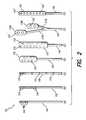
- FIG. 2illustrates examples of various types of electrode arrays that may be used with the system of FIG. 1;
- FIG. 3is a timing waveform diagram that depicts representative current waveforms that may be applied to various ones of the electrode contacts of the electrode arrays through one or more stimulus channels;
- FIG. 4Ais a block diagram that illustrates the main components of a representative implantable pulse generator that may be used with the invention
- FIG. 4Bshows an IPG hybrid block diagram that illustrates the architecture of an IPG made in accordance with a second IPG embodiment of the invention
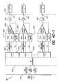
- FIGS. 4C-1, 4 C- 2 and 4 C- 3show a block diagram, spread over three drawing sheets, of the analog integrated circuit (AIC) used, intra alia, to provide the output of the stimulus generators within the IPG hybrid architecture shown in FIG. 4B;
- AICanalog integrated circuit
- FIG. 5illustrates a type of hand-held programmer that may be used to program the IPG
- FIG. 6depicts a representative programming screen that may be used as part of the programming system features of the invention.
- FIGS. 7A, 7 B, 7 C and 7 Dshow the display of a human body, divided into regions, dermatones, or other subdivisions of the body, which display is presented on the programming screen, and further illustrate an exemplary sequence of selections made by a patient as the invention is used to match a region of pain with a region of paresthesia;
- FIG. 8is a flow chart that depicts the main steps associated with programming an implant device in accordance with the present invention.
- the present inventionrelates to an implantable device programmer, i.e., a method or system for programming, or programming apparatus for use with, an implant device so that the implant device carries out a desired function.
- the inventionwill be described with reference to the implanted pulse generator (IPG) used as part of a spinal cord stimulation (SCS) system.
- IPGimplanted pulse generator
- SCSspinal cord stimulation
- An exemplary SCS systemis described more fully in previously referenced U.S. patent applications, Ser. Nos. 09/626,010, 09/668,925 and 60/172,167, now U.S. Pat. No. 6,381,496 B1. It is to be understood, however, that the present invention is not limited for use just within an SCS system of the type described in the referenced patent applications.
- the inventionhas broad applicability, and may be used with numerous different types of implant devices and systems used to alleviate pain or produce other desired results, and wherein feedback from the patient may be obtained regarding areas or regions where paresthesia or other sensations are felt as a result of applied electrical stimuli.
- implant devices and systemsused to alleviate pain or produce other desired results, and wherein feedback from the patient may be obtained regarding areas or regions where paresthesia or other sensations are felt as a result of applied electrical stimuli.
- Such systemsmay include all types of neural stimulators and sensors, deep brain stimulators, cochlear stimulators, drug delivery systems, muscle tissue stimulators, and the like.
- FIG. 1there is shown a block diagram that illustrates the various components of an exemplary SCS system, including an implantable pulse generator (IPG) and hand-held programmer (HHP) used with such system.
- IPGimplantable pulse generator
- HHPhand-held programmer
- these componentsmay be subdivided into three broad categories: (1) implantable components 10 , (2) external components 20 , and (3) surgical components 30 .
- the implantable components 10include an implantable pulse generator (IPG) 100 , an electrode array 110 , and (as needed) an extension 120 .
- the extension 120is used to electrically connect the electrode array 110 to the IPG 100 .
- IPG 100Different embodiments of a suitable IPG 100 are described more fully below in connection with FIG. 4 A and FIG. 4 B.
- the IPG 100 described belowcomprises a rechargeable, multichannel, telemetry-controlled, pulse generator.
- a suitable connectorallows the electrode array 110 or extension 120 to be detachably secured, i.e., electrically connected, to the IPG
- the IPG 100contains stimulating electrical circuitry (“stimulating electronics”), a power source, e.g., a rechargeable battery, and a telemetry system.
- a power sourcee.g., a rechargeable battery
- a telemetry systeme.g., a telemetry system.
- the IPG 100is placed in a surgically-made pocket either in the abdomen, or just at the top of the buttocks. It may, of course, also be implanted in other locations of the patient's body.
- the IPG 100is connected to the lead system, comprising the lead extension 120 , if needed, and the electrode array 110 .
- the lead extension 120may be tunneled up to the spinal column.
- the lead system 110 and lead extension 120are intended to be permanent.
- the IPG 100may be replaced when its power source fails or is no longer rechargeable.
- the IPG 100can provide electrical stimulation through a multiplicity of electrodes, e.g., sixteen electrodes, included within the electrode array 110 .
- electrode arrays 110Different types of electrode arrays 110 that may be used with the invention are depicted in FIG. 2.
- a common type of electrode array 110is the “in-line” lead, as shown at (A), (B), and (C) in FIG. 2 .
- An in-line leadincludes individual electrode contacts 114 spread longitudinally along a small diameter flexible cable or carrier 116 .
- the flexible cable or carrier 116has respective small wires embedded (or otherwise carried therein) for electrically contacting each of the individual electrode contacts.
- an in-line leadrelates to its ease of implantation, i.e., it can be inserted into the spinal canal through a small locally-anesthetized incision while the patient is kept awake. When the patient is awake, he or she can provide valuable feedback as to the effectiveness of stimulation applied to a given electrode contact or contacts 114 for a given positioning of the array 110 .
- One of the disadvantages of the in-line leadis that it is prone to migrating in the epidural space, either over time or as a result of a sudden flexion movement. Such migration can disadvantageously change the location and nature of the paresthesia and the required stimulation level.
- Either or both of the these conditionsmay require reprogramming of the IPG 100 and/or surgical correction (repositioning) of the electrode array 110 .
- the term “paresthesia”refers to that area or volume of the patient's tissue that is affected by the electrical stimuli applied through the electrode array. The patient may typically describe or characterize the paresthesia as an area where a tingling sensation is felt.
- each type of paddle leadis shaped with a wide platform 119 on which a variety of electrode contact configurations or arrays are situated.
- the paddle lead shown at (D) in FIG. 2has two columns of four rectangular-shaped electrode contacts 115 carried on a wide platform 119 , with the electrode contacts in one column being offset from the electrode contacts in the other column.
- offsetrefers to the vertical position of the electrode contacts, as the leads are oriented in FIG.
- the flexible cable or carrier 116carries wires from each electrode contact to a proximal end of the paddle lead (not shown), where such wires may be connected to the IPG 100 (or to a lead extension 119 , which in turn connects to the IPG 100 ).
- the paddle lead shown at (E) in FIG. 2similarly has two columns of eight electrode contacts 115 in each row, with the electrode contacts in one column being offset from the electrode contacts in the other column, and with each electrode contact being connected to one or more wires carried in the flexible cable or carrier 116 .
- one type of paddle leadhas its carrier or cable 116 branch into two separate branches 117 a and 117 b , with a wide platform 119 a and 119 b being located at a distal end of each branch. Within each wide platform 119 a and 119 b an array of at least two circular-shaped electrode contacts 115 ′ is situated.
- another type of paddle leadhas a wide platform 119 at its distal end on which a single column of circular-shaped electrode contacts 115 ′ is situated.
- Still other types of leadsmay be used with the IPG 100 (FIG. 1) in addition to the representative leads shown in FIG. 2 .
- the deployable electrode array disclosed in U.S. patent application Ser. No. 09/239,927, filed Jan. 28, 1999, now U.S. Pat. No. 6,205,361represents still another type of lead and electrode array that may be used with the invention.
- the '361 patentis incorporated herein by reference.
- an important feature of the SCS system shown in FIG. 1is the ability to support more than one lead with two or more channels.
- a “channel”is defined as a specified electrode, or group of electrodes, that receive a specified pattern or sequence of stimulus pulses.
- each channelmay be programmed to provide its own specified pattern or sequence of stimulus pulses to its defined electrode or group of electrodes.
- all of the stimulus patterns applied through all of the channels of such multi-channel systemthus combine to provide an overall stimulation pattern that is applied to the tissue exposed to the individual electrodes of the electrode array(s).
- One type of preferred electrode configurationuses a multiple lead system, e.g., two or four leads, with the leads placed side by side, or at different vertical locations.
- the individual electrodes on each vertical lead of such multiple lead systemeffectively create a desired electrode array that covers a large, or relatively large, tissue area.
- the respective electrodes of each vertical leadmay be aligned horizontally, offset horizontally, or randomly or systematically arranged in some other pattern.
- the electrode array 110 and its associated lead systemtypically interface with the implantable pulse generator (IPG) 100 via a lead extension system 120 .
- the electrode array 110may also interface with an external trial stimulator 140 through one or more percutaneous lead extensions 132 , connected to the trial stimulator 140 through an external cable 134 .
- the individual electrodes included within the electrode array 110may receive an electrical stimulus from either the trial stimulator 140 or the IPG 100 .
- the lead extension(s) 120As suggested in the block diagram of FIG. 1, the lead extension(s) 120 , as well as the percutaneous extension(s) 132 , are inserted through the patient's tissue through the use of appropriate surgical components 30 , and in particular through the use of tunneling tools 152 , as are known in the art, or as are especially developed for purposes of spinal cord stimulation systems.
- the electrode array 110is implanted in its desired position, e.g., adjacent the spinal column of the patient, through the use of an insertion needle 154 and a guide wire 156 .
- FIG. 3assumes the use of an electrode array 110 having sixteen electrodes connected to the implantable pulse generator (IPG) 100 .
- IPGimplantable pulse generator
- the horizontal axisis time, divided into increments of 1 millisecond (ms), while the vertical axis represents the amplitude of a current pulse, if any, applied to one of the sixteen electrodes.
- FIG. 3illustrates that a current pulse of 4 milliamps (mA) appears on channel 1 at electrode E 1 and E 3 .
- FIG. 3illustrates that a current pulse of 4 milliamps (mA) appears on channel 1 at electrode E 1 and E 3 .
- FIG. 3further shows that this current pulse is negative ( ⁇ 4 mA) on electrode E 1 and positive (+4 mA) on electrode E 3 . Additionally, FIG. 3 shows that the stimulation parameters associated with this current pulse are set at a rate of 60 pulses per second (pps), and that the width of the pulse is about 300 microseconds ( ⁇ s).
- channel 2 of the IPG 100is set to generate and apply a 6 mA pulse, having a repetition rate of 50 pps and a width of 300 ⁇ s, between electrode E 8 (+6 mA) and electrodes E 6 and E 7 ( ⁇ 4 mA and ⁇ 2 mA, respectively). That is, channel 2 of the IPG supplies a current pulse through electrode E 8 (+6 mA) that is shared on its return path through electrode E 6 ( ⁇ 4 mA) and electrode E 7 ( ⁇ 2 mA).
- channel 3 of the IPG 100is set to generate and supply a 5 mA pulse to electrode E 10 (+5 mA) which is returned through electrode E 8 ( ⁇ 5 mA).
- This pulseis provided at a rate of 60 pps, and a width of 400 ⁇ s.
- channel 4 of the IPGis set to generate and supply a 4 mA pulse to electrode E 14 (+4 mA) which is returned through electrode E 13 ( ⁇ 4 mA).
- This channel 4 pulsehas a rate of 60 pps and a width of 300 ⁇ s.
- any channel of the IPGmay be programmably connected to any grouping of the electrodes, including the reference (or case) electrode. While it is typical that only two electrodes be paired together for use by a given channel of the IPG, as is the case with channels 1 , 3 and 4 in the example of FIG. 3, it is to be noted that any number of electrodes may be grouped and used by a given channel.
- the sum of the current sourced from the positive electrodesshould be equal to the sum of the current sunk (returned) through the negative electrodes, as is the case with channel 2 in the example of FIG. 3 (+6 mA sourced from electrode E 8 , and a total of ⁇ 6 mA sunk to electrodes E 6 [ ⁇ 4 mA] and E 7 [ ⁇ 2 mA]).
- the IPGhas sixteen electrode contacts, each of which is independently programmable relative to stimulus polarity and amplitude for each of up to four different programmable channel assignments (groups or phase generators).
- each channelidentifies which electrodes among the sixteen electrodes, E 1 , E 2 , E 3 . . . E 16 and the IPG case electrode (reference electrode), are to output stimulation pulses in order to create an electric current field. All electrodes assigned to a given channel deliver their stimulation pulses simultaneously with the same pulse width and at the same pulse rate.
- the IPG case electrodeis programmable either as a Positive (passive anode) or OFF.
- monopolar stimulationis provided when the only electrode contact programmed to Positive is the IPG case electrode, and at least one other electrode is programmed to Negative.
- the polarityis programmable to: (1) Negative (cathode), with associated negative current amplitude; (2) Positive (anode), with an associated positive current limit amplitude; or (3) Off.
- An “active” phase periodis a phase period of the stimulus current during which the stimulus current is being provided by one or more of available turned ON current sources.
- a “passive” phase period(also sometimes referred to as a “recharge” phase period) is a phase period of the stimulus current during which the current sources are turned OFF, and the stimulus current results from a recharge or redistribution of the charge flowing from the coupling capacitance present in the stimulus circuit.
- Net DC charge transferis prevented during stimulation through the use of coupling capacitors C 1 , C 2 , C 3 , . . . C 16 (see FIG. 4A or 4 C) between the electrodes E 1 , E 2 , E 3 , . . . E 16 and the IPG output.
- a slow start/end featuremay be employed wherein changes in amplitude are limitable to occur slowly and smoothly over a transition period.
- an overlap arbitration circuitmay be optionally employed (that is, an arbitration feature may be programmed ON or OFF for each channel) that determines which channel has priority.
- the arbitration circuitfunctions in accordance with the following principles. Once a non-overlapping channel begins a pulse, the start of pulses from any other non-overlapping channel is delayed until the ongoing pulse phase one is completed and a Hold-Off period has been completed. The Hold-Off period is timed from the end of the first phase of the pulse. If the start of two or more non-overlapping channels are delayed by an ongoing pulse and Hold-Off period, the pending channels are started in the order they would have occurred without arbitration.
- the IPGincludes a microcontroller ( ⁇ C) 160 connected to memory circuitry 162 .
- the ⁇ C 160typically comprises a microprocessor and associated logic circuitry, which in combination with control logic circuits 166 , timer logic 168 , and an oscillator and clock circuit 164 , generate the necessary control and status signals which allow the ⁇ C to control the operation of the IPG in accordance with a selected operating program and stimulation parameters.
- the operating program and stimulation parametersare typically programmably stored within the memory 162 by transmitting an appropriate modulated carrier signal through a receiving coil 170 and charging and forward telemetry circuitry 172 from an external programing unit, e.g., a handheld programmer (HHP) 202 and/or a clinician programmer (CP) 204 , assisted as required through the use of a directional device 206 (see FIG. 1 ).
- an external programing unite.g., a handheld programmer (HHP) 202 and/or a clinician programmer (CP) 204 , assisted as required through the use of a directional device 206 (see FIG. 1 ).
- the charging and forward telemetry circuitry 172demodulates the carrier signal it receives through the coil 170 to recover the programming data, e.g., the operating program and/or the stimulation parameters, which programming data is then stored within the memory 162 , or within other memory elements (not shown) distributed throughout the IPG 100 .
- the microcontroller 160is further coupled to monitoring circuits 174 via bus 173 .
- the monitoring circuits 174monitor the status of various nodes or other points 175 throughout the IPG 100 , e.g., power supply voltages, current values, temperature, the impedance of electrodes attached to the various electrodes E 1 . . . En, and the like.
- Informational data sensed through the monitoring circuit 174may be sent to a remote location external the IPG (e.g., a non-implanted location) through back telemetry circuitry 176 , including a transmission coil 177 .
- the operating power for the IPG 100is derived from a replenishable power source 180 , e.g., a rechargeable battery and/or a supercapacitor.
- a replenishable power source 180e.g., a rechargeable battery and/or a supercapacitor.
- Such power source 180provides an unregulated voltage to power circuits 182 .
- the power circuits 182generate the various voltages 184 , some of which are regulated and some of which are not, as needed by the various circuits located within the IPG.
- the power circuits 182further selectively direct energy contained within the carrier signal, obtained through the charging and forward telemetry circuit 172 , to the replenishable power source 180 during a charging mode of operation. In this way, the power source 180 may be recharged when needed.
- the power source 180 of the IPG 100comprises a rechargeable battery, and more particularly a rechargeable Lithium Ion battery. Recharging occurs inductively from an external charging station. While recharging is shown in FIG. 4A as occurring through the forward telemetry coil 170 , it is noted that recharging may also occur through the back-telemetry coil 177 or through a separate charging coil. Because the SCS IPG 100 could accept or receive a charge from an unauthorized source, internal battery protection circuitry is employed, for safety reasons, to protect the battery (e.g., to prevent the battery from being overcharged and/or to accept a charge only from an authorized charging device). Also, safeguarding features are incorporated that assure that the power source, e.g., battery, is always operated in a safe mode upon approaching a charge depletion.
- the power sourcee.g., battery
- the IPG 100is able to monitor and telemeter the status of its replenishable power source 180 (e.g., rechargeable battery) each time a communication link is established with the external patient programmer 202 , or at other select times. Such monitoring not only identifies how much charge is left, but also charge capacity.
- a programming eventi.e., each time the patient or medical personnel change a stimulus parameter, or initiate a charging operation, a telecommunicative link is established with the implant device, and hence battery monitoring may occur.
- a plurality m of independent current source pairs186 +I 1 , 186 ⁇ I 1 , 186 +I 2 , 186 ⁇ I 2 , 186 +I 3 , 186 ⁇ I 3 , . . . 186 +Im, 186 ⁇ Imare coupled to the control logic 166 via control bus 167 .
- One current source of each pair of current sourcesfunctions as a positive (+) current source, while the other current source of each pair functions as a negative ( ⁇ ) current source.
- the output of the positive current source and the negative current source of each pair of current sources 186is connected to a common node 187 .
- This common node 187is connected through a low impedance switching matrix 188 to any of n electrode nodes E 1 , E 2 , E 3 , . . . En, through respective coupling capacitors C 1 , C 2 , C 3 , . . . Cn.
- a second embodiment of the IPGsee FIGS. 4B and 4C, discussed below, does not use a low impedance switching matrix 188 . Rather, in the second embodiment, there is an independent bi-directional current source for each of the sixteen electrodes.
- the switching matrix 188Through appropriate control of the switching matrix 188 , when used (FIG. 4 A); or through operation of the independent bi-directional current sources, when used (FIGS.
- any of the m current source nodes 187may be connected to any of the electrode nodes E 1 , E 2 , E 3 , . . . En.
- the current source 186 +I 1to produce a pulse of +4 mA (at a specified rate and for a specified duration)
- the current source 186 ⁇ I 2to similarly produce a pulse of ⁇ 4 mA (at the same rate and pulse width)
- the 186 +I 1 node 187 to electrode node E 3 and the 186 ⁇ I 2 node to electrode node E 1 at relative time t0 ms (and at a recurring rate thereafter) in order to realize the operation of channel 1 depicted in the timing diagram of FIG. 3 .
- the operation of channels 2 , 3 and 4 shown in FIG. 3may likewise be realized.
- any of the n electrodesmay be assigned to up to k possible groups (where k is an integer corresponding to the number of channels, and in a preferred embodiment is equal to 4). Moreover, any of the n electrodes can operate, or be included in, any of the k channels.
- the channelidentifies which electrodes are selected to synchronously source or sink current in order to create an electric field. Amplitudes and polarities of electrodes on a channel may vary, e.g., as controlled by the patient hand held programmer (HHP) 202 .
- External programming software in the clinician programmer 204is typically used to assign a pulse rate and pulse width for the electrodes of a given channel.
- each of the n programmable electrode contactscan be programmed to have a positive (sourcing current), negative (sinking current), or off (no current) polarity in any of the k channels.
- each of the n electrode contactscan operate in a bipolar mode or multipolar mode, e.g., where two or more electrode contacts are grouped to source/sink current at the same time.
- each of the n electrode contactscan operate in a monopolar mode where, e.g., the electrode contacts associated with a channel are configured as cathodes (negative), and the case electrode, on the IPG case, is configured as an anode (positive).
- the amplitude of the current pulse being sourced or sunk from a given electrode contactmay be programmed to one of several discrete levels. In order to prevent “jolts”, current amplitude changes may be gradually changed, e.g., in a ramping fashion, from one value to another within the range of values available between the settings. Such ramping feature is also used when initially powering on the IPG, thereby preventing full magnitude stimulus pulses from being delivered to the patient during a ramping-up time period, and a ramping-down period is used when powering off the IPG.
- the ramping-up and ramping-down time periodsmay vary, depending upon the channel and programmed amplitude, between about 1 and 10 seconds.
- the pulse width of the current pulsesis adjustable in convenient increments.
- the pulse rateis adjustable within acceptable limits.
- the stimulation pulses generated by the IPG 100are typically charged balanced. This means that the amount of positive charge associated with a given stimulus pulse must be offset with an equal and opposite negative charge. Charge balance may be achieved through a coupling capacitor, which provides a passive capacitor discharge that achieves the desired charge balanced condition. Such passive capacitor discharge is evident in the waveforms depicted in FIG. 3 as the slowly decaying waveform following the short trailing edge of each pulse. Alternatively, active biphasic or multiphasic pulses with positive and negative phases that are balanced may be used to achieve the needed charge balanced condition.
- a real-time clockis also incorporated within the timing circuits of the IPG 100 .
- Such real-time clockadvantageously allows a run schedule to be programmed. That is, the patient can schedule auto-run times for IPG operation at certain times of the day.
- an auto-run timebegins, all channels are enabled and provide a previously-programmed pattern of stimulus currents, i.e., current pulses having a programmed width, rate, and amplitude are generated and delivered through each channel.
- the auto-run timecontinues for a set time period, e.g., several hours, or for only a few minutes.
- the auto-run timewhen enabled at the programmed time of day, invokes the most recent programming changes made to each channel.
- An important feature included within the IPG 100is its ability to measure electrode impedance, and to transfer the impedance thus measured back to a remote programmer, or other processor, through the back telemetry circuits 176 .
- the microcontroller 160in combination with the other logic circuits, may also be programmed to use the electrode impedance measurements to adjust compliance voltages and to thereby better maintain low battery consumption.
- the electrode impedancewill typically range between about 400 ohms and 1000 ohms.
- FIG. 4AThe type of current sources depicted in FIG. 4A may be realized by those of skill in the art using any suitable circuitry.
- teachings of International Patent Application Serial Number PCT/US99/14190, filed Jun. 23, 1999, entitled “Programmable Current Output Stimulus Stage for Implantable Device”, published as International Publication No. WO-00/00251, on Jan. 6, 2000,could be used.
- the WO-00/00251 publicationis incorporated herein by reference.
- ASICapplication specific integrated circuit
- FIG. 4Ba hybrid block diagram of an alternative embodiment of an IPG 100 ′ that may be used with the invention is illustrated.
- the IPG 100 ′includes both analog and digital dies, or integrated circuits (IC's), housed in a single hermetically-sealed rounded case. Many of the circuits contained within the IPG 100 ′ are identical or similar to the circuits contained within the IPG 100 , shown in FIG. 4 A.
- the IPG 100 ′includes a processor die, or chip, 160 ′, an RF telemetry circuit 172 ′ (typically realized with discrete components), a charger coil 171 ′, a lithium ion battery 180 ′, battery charger and protection circuits 182 ′, memory circuits 162 ′ (SEEROM) and 163 ′ (SRAM), a digital IC 191 ′, an analog IC 190 ′, and a capacitor array and header connector 192 ′.
- the capacitor array and header connector 192 ′includes 16 output decoupling capacitors, as well as respective feed-through connectors for connecting one side of each decoupling capacitor through the hermetically-sealed case to a connector to which the electrode array 110 , or lead extension 120 , may be detachably connected.
- the processor 160 ′is realized with an application specific integrated circuit (ASIC) that comprises the main device for full bi-directional communication and programming.
- the processor 160 ′utilizes an 8086 core (the 8086 is a commercially-available microprocessor), 16 kilobytes of SRAM memory, two synchronous serial interface circuits, a serial EEPROM interface, and a ROM boot loader.
- the processor die 160 ′further includes an efficient clock oscillator circuit 164 ′ and a mixer and modulator/demodulator circuit implementing the QFAST RF telemetry method supporting bi-directional telemetry at, 8 Kbits/second.
- QFASTstands for “Quadrature Fast Acquisition Spread Spectrum Technique”, and represents a known and viable approach for modulating and demodulating data (see U.S.
- An analog-to-digital converter (A/D) circuit 734is also resident on the processor 160 ′ to allow monitoring of various system level analog signals, impedances, regulator status and battery voltage.
- the processor 160 ′further includes the necessary communication links to other individual ASIC's utilized within the IPG 100 ′.
- the analog IC (AIC) 190 ′comprises an ASIC that functions as the main integrated circuit that performs several tasks necessary for the functionality of the IPG 100 ′, including power regulation, stimulus output, and impedance measurement and monitoring.
- Electronic circuitry 194 ′performs the impedance measurement and monitoring function.
- the main area of the analog 190 ′is devoted to the current stimulus generators 186 ′. These generators 186 ′ may be realized using the circuitry described in the previously-referenced PCT application, International Publication No. WO-00/00251, or similar circuitry.
- Regulators for the IPG 100 ′supply the processor and the digital sequencer with a suitable voltage, e.g., 2.7 V ⁇ 10%.
- Digital interface circuits residing on the AIC 190 ′are similarly supplied with a suitable operating voltage, e.g., 2.7 V ⁇ 10%.
- a regulatorthat is programmable from, e.g., 5V to 18V, supplies the operating voltage for the output current DACs 186 ′.
- FIG. 4 CA block diagram of the output stimulus generators 186 ′ included within the AIC 190 ′ is shown in FIG. 4 C.
- a data bus 4 C 01 from the digital IC 191 ′couples data received from the digital IC to AIC sequencer circuits 4 C 02 .
- Such dataincludes odd and even amplitude data, odd and even mode data, and odd and even change data, where “odd” and “even” refer to the electrode number (with electrodes E 1 , E 3 , E 5 , etc.
- a multiplicity of latch circuits 4 C 03are connected to the AIC sequencer 4 C 02 , one latch circuit for each electrode.
- Each latch circuitincludes an amplitude bus 4 C 04 on which the amplitude data is placed, an S 1 line for designating a positive amplitude, an S 2 line for designating a negative amplitude, and an S 3 line for designating a recharge state.
- a PDAC circuit 4 C 05is enabled by a signal on the S 1 line when a current having the amplitude specified on the amplitude bus 4 C 04 is to be sourced from a current source 4 C 06 through a coupling capacitor Cn, where n is an integer from 1 to 16 .
- an NDAC circuit 4 C 07is enabled by a signal on the S 2 line when a current having the amplitude specified on the amplitude bus 4 C 04 is to be sunk into the current source 4 C 06 through the coupling capacitor Cn.
- a recharge switch 4 C 08is enabled by the signal on the S 3 line when it is desired to remove the charge from the coupling capacitor Cn.
- Another switch 4 C 09allows an indifferent electrode 4 C 11 , e.g., the case of the IPG, to be turned on upon receipt of an SC 1 signal.
- a recharge switch 4 C 10allows the indifferent electrode 4 C 11 to be selectively connected to ground, or another voltage source, upon receipt of an SC 2 signal.
- the analog IC 186 ′includes a multiplicity of output current sources 4 C 06 , e.g., sixteen bi-directional output current sources, each configured to operate as a DAC current source.
- Each DAC output current source 4 C 06may source or sink current, i.e., each DAC output current source is bi-directional.
- Each DAC output current sourceis connected to an electrode node 4 C 11 .
- Each electrode node 4 C 11is connected to a coupling capacitor Cn.
- the coupling capacitors Cn and electrode nodes, as well as the remaining circuitry on the analog IC 186 ′,are all housed within the hermetically sealed case of the IPG 100 .
- the dashed-dotted line 4 C 12represents the boundary between the sealed portion of the IPG case and the unsealed portion.
- a feedthrough pin 4 C 13which is included as part of the header connector 192 ′ (FIG. 4 B), allows electrical connection to be made between each of the coupling capacitors Cn and the respective electrodes E 1 , E 2 , E 3 . . . , or E 16 , to which the DAC output current source is associated.
- a digital IC (DigIC) 191 ′is also provided as part of the IPG 100 ′ that functions as the primary interface between the processor 160 ′ and the AIC output circuits 186 ′.
- the main function of the DigIC 191 ′is to provide stimulus information to the output current generator register banks. The Dig IC 191 ′ thus controls and changes the stimulus levels and sequences when prompted by the processor 160 ′.
- the RF circuitry 172 ′includes antennas and preamplifiers that receive signals from the HHP 202 and provide an interface at adequate levels for the demodulation/modulation of the communication frames used in the processor 160 ′. Any suitable carrier frequency may be used for such communications. In a preferred embodiment, the frequency of the RF carrier signal used for such communications is 262.144 KHz, or approximately 262 MHz.
- the Battery Charger and Protection Circuits 182 ′provide battery charging and protection functions for the Lithium Ion battery 180 ′.
- a charger coil 171 ′inductively (i.e., electromagnetically) receives rf energy from the external charging station.
- the battery charger circuitsperform three main functions: (1) during normal operation, they continually monitor the battery voltage and provide charge status information to the patient at the onset of a communication link, (2) they ensure that the battery is not over-discharged, and (3) they monitor the battery voltage during a charging cycle to ensure that the battery does not experience overcharging.
- the implant portion 10 of the SCS system of the present inventionincludes an implantable pulse generator (IPG) 100 or 100 ′ as described in FIGS. 4A-4C.
- IPGimplantable pulse generator
- Such IPGfurther includes stimulating electronics (comprising programmable current sources and associated control logic), a power source, and a telemetry system.
- the power sourcemay be recharged over and over again, as needed, and may thus provide a long life, as well as a high current output capacity.
- An important feature of the present inventionis its ability to map current fields through selective control of the current sources which are attached to each electrode node.
- the inventionachieves its desired function of being able to independently map a desired current to each electrode node through the use of a processor 160 ′, one or more ASIC's 190 ′ or 191 ′, sixteen independent bi-directional output current DACs (FIG. 4C, elements 4 C 05 - 4 C 07 ), and timers and control registers, configured to operate in a state machine architecture.
- the ASIChas a standard bus interface to the microcontroller allowing simple, direct and efficient access to all of its control and stimulation parameter registers. Triggering and timing control circuitry allow the simultaneous activation of any of the channels.
- a low impedance switching matrixadvantageously allows the mapping of each current generator's two outputs to be assigned to any of the pulse generator electrode nodes (or leadwires, which are attached to the electrode nodes) or to the case.
- FIGS. 4 B and 4 Cthere is no need for a low impedance switching matrix. Rather, independent bi-directional current sources for each of the sixteen electrodes (independently operable output current DACs) allow the output currents to be mapped to any of the output electrode nodes or to the case.
- one or more current generatorsmay be attached to any one or more electrode nodes (leadwires) and thus electrodes, and conversely, any electrode node (leadwire) may be attached to one or more current generator outputs, grounded, or left open.
- the significance of the biphasic, or (in some instances) multiphasic, nature of the stimulation pulsesis that currents may be actively driven in either the anodic or cathodic direction to the output electrode nodes of the current generators.
- This featurealong with the matrix switching of output leads, or independently operable output current DACs, depending upon the embodiment used, allows the creation of “virtual” electrodes and stimulation current field control, not possible with other known designs. This feature thus provides an important advance in the ability to direct the stimulation pulses to pools of target neurons in the spinal cord.
- the systemis programmed to provide a desired stimulation pattern at desired times of the day.
- the stimulation parametersthat can be programmed include the number of channels (defined by the selection of electrodes with synchronized stimulation), the stimulation rate and the stimulation pulse width.
- the current output from each electrodeis defined by polarity and amplitude.
- a run schedulemay be downloaded and stored in the memory of the IPG 100 , which when used enables (or turns on) the IPG at pre-programmed times of the day.
- the back telemetry features of the IPG 100advantageously allow the status of the IPG to be checked. For example, when the external hand-held programmer 202 (and/or the clinician programmer 204 ) initiates a programming session with the implant system 10 (FIG. 1 ), the capacity of the battery is telemetered so that the external programmer can calculate the estimated time to recharge. Additionally, electrode impedance measurements are telemetered at the beginning of each programming session, or as requested. Any changes made to the current stimulus parameters are confirmed through back telemetry, thereby assuring that such changes have been correctly received and implemented within the implant system. Moreover, upon interrogation by the external programmer, all programmable settings stored within the implant system 10 may be uploaded to one or more external programmers.
- This systemincludes, as seen in FIG. 1, a clinician programmer 204 coupled to a directional device 206 .
- the clinician programmer 204typically interfaces with a patient hand-held programmer (HHP) 202 in communicating with the implanted pulse generator (IPG) 100 .
- HHPpatient hand-held programmer
- IPGimplanted pulse generator
- other types of communication links between the clinician programmer 204 (also referred to herein as a programming computer) and the IPG 100may be utilized.
- the programming systemmaintains a patient data base, and is able to program all features of the implant device in a simple and intuitive manner. Preprogrammed into the data base, along with information about the patient, is known information regarding anatomical relationships between the spine and the body. Additionally, the system allows threshold measurements to be made, operational electrodes to be identified, and is able to interface directly with the patient.
- a key feature of the SCS programming systemis the use of a joystick accessory, or equivalent directional device 206 (FIG. 1 ), which allows the patient to interface with a laptop computer (e.g., programmed to function as the clinician programmer 204 ), or other processor (e.g., a hand-held computer, such as a PalmPilot® computer, or equivalent) so as to allow the patient, or other medical personnel assisting the patient, to configure electrodes and adjust various stimulation parameters and to identify regions of the body where pain is present and where a paresthesia is felt.
- a laptop computere.g., programmed to function as the clinician programmer 204
- processore.g., a hand-held computer, such as a PalmPilot® computer, or equivalent
- One suitable directional programming deviceis described in more detail in U.S. Pat. No. 6,052,624, entitled “Directional Programming for Implantable Electrode Arrays”, which patent is incorporated herein by reference.
- such directional programmingmay advantageously be performed either in the operating room (OR) environment and in the doctor's office.
- the clinician or nursesimply operates the joystick feature, or equivalent directional programming feature, during surgery in conjunction with the trial stimulator 140 so as to configure and select the electrodes that provide desired stimulation.
- the patientthen uses the joystick feature to finalize the device programming during a post implant adjustment session.
- the directional programming device 206is able to be effectively used to configure which electrodes provide stimuli to the patient.
- the directional programming devicemay take many forms. For purposes of the present invention, any device that allows a computer-generated cursor (or other indicator) to move about on the display screen of the computer as controlled by the user will suffice.
- Representative directional programming devicesinclude keys on a keyboard (e.g., arrow keys), a mouse, a track ball, a touch-sensitive screen over which the users finger may be moved, voice commands in combination with voice recognition software, light sensors on which a light beam, e.g., a laser wand, may be directed, and the like.
- the clinician programming systemcommunicates to the patient HHP 202 over a telecommunicative or other communication link 203 , which then telemeters the data to the IPG 100 .
- the clinician's programmeris able to communicate to the trial stimulator 140 over the telecommunicative link 205 .
- the communication links 203 and 205are reliable links capable of operating in the busy OR environment. Data speeds to and from the IPG 100 , through the patient programmer 202 intermediary link, are fast enough to not noticeably delay programming.
- a communication link status between devicesis always depicted on a screen, or other display device, associated with the programmer 204 .
- the systemidentifies the stimulator, the patient programmer, and electrode availability (through electrode impedance measurements).
- the patient programmer 202is coded to work only with a specific implant system. Should the patient lose his or her programmer 202 , then the physician, using the clinician programmer, is able to code a new programmer for use with the patient's implant system.
- the clinician's programmerin contrast, is able to communicate to any implant through any programmer 202 by using an overriding universal code. This allows the patient code to be extracted from the IPG 100 and used to re-code a new programmer 202 .
- the device settings and hardware informationare first uploaded to the clinician programmer 204 .
- All devices in the link with the IPGe.g., the hand held device 202 , and/or the trial stimulator 140 , and clinician programmer 204 , and the clinician programmer 204 , are synchronized so that each device receives accurate and current data.
- Programming changes made to the stimulator(s)are confirmed through back telemetry or other means before the SCS add-on software reflects the change.
- the physicianis able to program the stimulator through either the patient programmer 202 or the clinician programmer 204 while linked together through the link 203 , with all programming changes being mirrored in both devices.
- HHPhand-held programmer
- the HHP 202is housed within a hand-held case 220 .
- Displayed on the case 220are a set of intuitive control buttons 224 , 225 that control the operation of the device.
- the HHP 202is compact in size, and can be easily held in one hand.
- a belt clipis placed on its back side, thereby allowing it to be worn on a patient belt, much like a pager or cell-phone.
- the device caseincludes an accessible battery compartment wherein replaceable (and/or rechargeable) batteries may be carried having sufficient capacity to provide operating power to its internal circuitry for at least one week.
- HHPpatient handheld programmer
- the SCSfurther provides a programming window that facilitates programming the stimulator, or IPG.
- the programming windowmay, in one embodiment, include tiered sub-windows, which may be titled, e.g., “measurements”, “programming”, and “advanced”.
- the measurement windowwhich may also be referred to as a “threshold” window, is used to set maximum and minimum thresholds, and to map pain and paresthesia with implanted electrodes to anatomical sites in accordance with the present invention. Mapping of maximum and minimum thresholds is preferably done in a way that normalizes the measured threshold values for each channel to fall within a range of “1” (minimum threshold) to “10” (maximum threshold), as described more fully in the previously-referenced copending patent application Ser. No. 60/172,167, filed Dec. 17, 1999, now U.S. Pat. No. 6,381,496 B1.
- a representative programming windowis illustrated in FIG. 6 .
- included in the displayis a representation 230 of the type and orientation of the electrode array(s) that have been selected. Such selection is made from a group of possible electrode choices. Monopolar and bipolar sensitivity (max and min) thresholds are determined for each electrode for the displayed electrode array configuration.
- a human Figure 234is displayed on the display screen associated with the programming computer. This human Figure 234 is divided into body regions. Such body regions are also referred to, for purposes of the present invention, as “dermatones,” “body subdivisions,” “body areas,” or similar language, as described more fully below in conjunction with the description of FIGS. 7A-7D.
- a pain or paresthesia area or regionis activated by toggling a color box, e.g., red or blue, that is superimposed over the affected body area.
- a color boxe.g., red or blue
- One colore.g., is used to represent pain; while the other color, e.g, blue, is used to represent paresthesia.
- the paresthesia coloris always transparent (top layered) so that pain segments can be seen through it. Multiple body segments can be selected individually, or as a group at intersections. By clicking on a segment, the active color is toggled off and on without affecting the alternate color.
- the objectis to match or map the paresthesia segments with the pain segments.
- Such pain/paresthesia mapping featuremay advantageously be used with expert algorithms to automate the programming process.
- the patient and clinician/physicianmay simply work together and use a trial-and-error procedure in order to best fit the paresthesia segments with the pain segments.
- FIGS. 7A, 7 B, 7 C and 7 Dwhere the human Figure 234 displayed on the programming screen is shown in more detail.
- the human Figure 234is divided into a multiplicity different regions 239 a , 239 b , 239 c , . . . 239 y .
- regions 239 a , 239 b , . . . 239 ymay also be referred to as “dermatones,” “body subdivisions,” “body areas,” or similar language.
- FIG. 234 shown in FIGS. 7A-7Dis shown as being divided into twenty-five such regions 239 ( 239 a through 239 y ), such number of regions is only exemplary.
- the patientfirst identifies a region of pain.
- a region 240(depicted in FIG. 7A as a right-slanting-hatched area, but preferably depicted on the programming screen in FIG. 6 by a different color, e.g., red) as a region of pain.
- This pain region 240comprises the two regions 239 m and 239 o on the left side of the patient comprising the lower back and pelvic areas.
- Such pain region 240may be identified by simply moving the cursor over areas 239 m and 239 o and clicking a button, e.g., a mouse button or a keyboard button.
- the programming computeruses known data regarding the relationships between the electrode physical locations and the body to select a first electrode combination through which a stimulus of selected operating parameters may be applied. Once selected, a stimulus having the selected operating parameters is applied to the selected electrode combinations to test whether the resulting paresthesia is in the same location as the pain region 240 .
- the patientidentifies the location of the paresthesia on the human FIG. 234 .
- the patientsenses the paresthesia in a paresthesia region which is identified as region 242 in FIG. 7 B. (depicted in FIG. 7B as a left-slanting-hatched area, but preferably depicted on the programming screen in FIG.
- the paresthesia areacomprises the individual regions 239 m , 239 n and 239 p , one region of which, 239 m , overlaps with a portion of the pain region 240 , but the other regions of which, 239 n and 239 p , do overlap with the pain region 240 .
- the programming computeruses this information, in combination with other information stored therein, to determine what modifications need to be made to the stimulation parameters or electrode selection in order to steer the paresthesia region 242 (left-slanting-hatched area) over the pain region (right-slanting-hatched area).
- the newly selected stimulus parametersincluding the selected electrode combination, may produce a new paresthesia region 244 that not only moves over the pain region 240 but also extends down into the left leg into regions 239 r and 239 s , as shown in FIG. 7C.
- a subsequent iterationi.e., the selection of a different electrode combination and/or the modification of the stimulus parameters produces a new paresthesia region 246 (left-slanting-hatched area) that matches, or merges with, the pain region 240 , as illustrated in FIG. 7 D.
- the programming datae.g., the operating parameter set, including the selected electrode combination
- the programming datamay be programmed into the memory of the implantable pulse generator so that such data can thereafter be used to control the operation of the IPG, and to further aid in subsequent programming sessions.
- a first preliminary step associated with the methodinvolves creating a data base and storing such data base in the memory of the programming computer that maps various electrode combinations to paresthesia regions.
- data basemay include data relating to known anatomical relationships between the spine and the body, as well as other known medical data.
- the methodnext includes displaying the human figure on a programming screen (block 262 of FIG. 8) divided into regions.
- the programming software that performs this function of displaying a human figuremay be referred to as first program data.
- the patientselects those regions (one or more) on the human figure which best represent the locations where he or she feels pain (block 264 ).
- the programming computerIn response to the patient selection which identifies the pain region, the programming computer automatically selects an electrode combination and stimulation parameters which, according to its programming software, would best provide a paresthesia region for the patient that matches the identified pain region (block 266 ).
- the data in the data base stored in the computeraids in this process.
- the data in the data basemay indicate that if pain is identified in location “X” (which X is any of the regions 239 a , 239 b , 239 c , . . . shown in FIG. 7 A), then a stimulus should be provided through electrode “Y”, where electrode “Y” is one of the electrodes connected to the IPG.
- the stimulus parametersmay initially be selected as nominal parameters. Selection algorithms, implemented in software or firmware within the computer, may be readily fashioned by those of skill in the art to automatically make this initial selection.
- the programming software that performs the function of making the initial electrode and stimulus parameter selectionmay be referred to as second program data.
- the programming computeruses the appropriate command signals to cause the implantable pulse generator (IPG) to stimulate the patient through the selected electrode combination (block 268 ).
- IPGimplantable pulse generator
- the patientsenses a region of paresthesia, and is thus able to identify the region of paresthesia on the displayed human figure (block 270 ).
- the programming computeruses an appropriate algorithm which may be referred to as third program data, determines the degree of mismatch between the pain region and paresthesia region (block 272 ).
- Such matching algorithmin one form, simply quantifies the amount of overlap between the identified paresthesia region and the selected pain region using the defined regions 239 a , 239 b , 239 c , . . . (see FIG. 7A) on the human figure.
- Other, more sophisticated matching algorithmsas are known in the art, may also be used for this purpose.
- a further iteration of selecting a new electrode combination and/or stimulus parametersis needed.
- Such further iterationinvolves having the programming computer select a new electrode combination and stimulation parameters (block 278 ).
- Such selectionis made based on the paresthesia region information provided by the patient and other data stored in the data base.
- information and datamay be referred to as fourth program data.
- the fourth program datawill typically comprise the second program data referred to above, modified in accordance with the paresthesia region information provided by the patient. It is the function of the fourth program data to modify the electrode combination and stimulation parameter selection so as to move the paresthesia region closer to the pain region, so that eventually the two regions merge or overlap.
- an option associated with the inventionallows the patient to identify the relative strength of the paresthesia in each region (block 276 ). That is, the patient may indicate whether the paresthesia sensed in human figure region 239 m is stronger than the paresthesia sensed in human figure regions 239 n or 239 p . Such comparative paresthesia strength data is then used by the programming computer, when available, to guide the new selection of electrode combinations and stimulation parameters (block 278 ).
- the electrode selection and stimulation parameters that resulted in such match conditionmay be sent to and stored in the IPG, or other implant device, to control the operation of the device in a manner that regularly overlays the paresthesia region on the pain region.
- the data base created in the computer memoryis preferably updated with the data that produced the match condition. Should the pain region move over time, then the programming process shown in FIG. 8 can be repeated, as required.
- the method shown in FIG. 8, or variations thereofprovides a method for use with a programming device linked with an implantable device, such as an implantable spinal cord stimulator, that allows the patient to easily identify a region of pain and then a region of paresthesia, so that the programming device may then automatically change selected stimulation parameters, including selected combinations of electrodes, to cause the region of paresthesia to overlap or merge with the region of pain, thereby alleviating the pain.
- an implantable devicesuch as an implantable spinal cord stimulator
- the programming window screenis also used to program electrode configurations and the desired output parameters for each of the available channels, e.g., each of four channels.
- the channelsare selected for programming by pointing and clicking using a mouse or other similar pointing/selection device. The default selection is the first channel. Selecting a channel causes the output parameters and electrodes for that channel to be displayed, so that they can be manipulated. Once selected, continual clicking of the channel toggles stimulation between active ON and PAUSED, with a settable soft start. This soft start feature is explained in more detail below. Selection of another channel does not change any of the settings of a previous channel.
- a channel that has been selected as an active ON channelis represented by stimulation pulses, see area 238 .
- Channelsare identified by number, but can also be selectively or automatically named by paresthesia location (i.e., legs, back, left arm, etc.) from mapping functions.
- the array type and orientationmust be selected.
- the number of implanted and available electrodesis typically automatically determined by impedance measurements during hardware interrogation.
- Pointing to the electrode box 230provides an electrode array selection, based on the number of detected electrodes, with preset visual forms.
- the array configurationis selected, it is displayed on the screen with point and click selectable electrodes. For example, one click may be used to specify a cathode; two clicks to specify an anode; and a third click to specify a neutral (floating or non-connected) electrode. Cathode, anode and neutral selections are indicated by a color change. By clicking an electrode to a cathode or anode state, the electrode is assigned to the active channel. If desired, a representation of current fields created by electrodes of a channel may also be displayed within this representation.
- amplitude, pulse width and rateare adjustable by mouse or arrow keys for the selected channel, using e.g., the “channel settings” area 232 of the programming screen.
- amplitude, on this main programming screenis programmable by channel, and applied as a distribution between maximum and sense thresholds for channel assigned electrodes.
- the amplitude for the channelis selected as a level from 1 through 10 where a “1” represents the sense threshold for each electrode in the channel, and a “10” represents the maximum threshold, as described in the previously-referenced patent application Ser. No. 60/172,167, now U.S. Pat. No. 6,381,496 B1.
- the actual magnitude or amplitude of the current, in mAmay be displayed, as shown in FIG. 6, or may not be displayed.
- the pulse width and rateare also selectable for the channel, and applied to the channel-assigned electrodes.
- each electrodeis individually controlled by the implant, and telemetered data is electrode specific.
- the number of additional channelsmay be limited (due to battery capacity).
- a toggle lock/unlock button for each parameterallows the programming physician to set which parameters are available within the patient hand-held programmer 202 (FIG. 1 ).
- the settings for up to four channelsare referred to as a “program.”
- Programsmay thus comprise a program.
- a store/apply buttonrecords all the settings with a program number.
- up to twenty programscan be named, stored and selected form a drop-down program list.
- programsmay be sequentially or selectively tried by the patient so that the patient may compare how one “program” feels compared to another.
- the advanced programming windowgenerally allows the output parameters for each channel to be programmed with additional capability and specificity. For example, biphasic verses passive balance pulses, active multipolar driving of cathodes and anodes (field focusing), and amplitude selection for individual electrodes.
- Unique programming algorithmsmay also be employed which provide, e.g., automated and directional programming features.
- Automated programmingmay be used, e.g., to use known thresholds and pain/paresthesia mapping to recommend configurations and parameters based on preset rules and database information.
- Automated programmingadvantageously maps paresthesia sites over pain sites.
- Directional programming featuresmay be as disclosed, e.g., in U.S. Pat. No. 6,052,624, previously referenced.
- Such directional programminguses a joystick, or other means, to configure electrodes within certain limitations for selection, polarity, and amplitude distribution in response to a directional input and in an intuitive and physiologic manner.
- the programming software used within the clinician programmer 204may run under conventional operating systems commonly used within personal computers (PCs).
- the preferred clinician programmeris a Pentium-based PC, operating at 100 MHz or more, with at least 32 Mbytes of RAM. Examples of an operating system for use in such a system include Windows 95/98/00 or Windows NT 4.0.
- Such programming softwarealso supports multiple languages, e.g., English, French. German, Spanish, Japanese, etc.
- the present inventionprovides a programming device or apparatus for use with an implantable stimulator, such as an implantable spinal cord stimulator.
- an implantable stimulatorsuch as an implantable spinal cord stimulator.
- the programming deviceallows the patient to easily identify a region of pain and then a region of paresthesia.
- the programming deviceuses this information to automatically change the selected stimulation parameters, including the selected combinations of electrodes, to cause the region of paresthesia to overlap or merge with the region of pain, thereby alleviating the pain.
Landscapes
- Health & Medical Sciences (AREA)
- Engineering & Computer Science (AREA)
- Radiology & Medical Imaging (AREA)
- Biomedical Technology (AREA)
- Nuclear Medicine, Radiotherapy & Molecular Imaging (AREA)
- Life Sciences & Earth Sciences (AREA)
- Animal Behavior & Ethology (AREA)
- General Health & Medical Sciences (AREA)
- Public Health (AREA)
- Veterinary Medicine (AREA)
- Neurosurgery (AREA)
- Neurology (AREA)
- Human Computer Interaction (AREA)
- Pain & Pain Management (AREA)
- Electrotherapy Devices (AREA)
Abstract
Description
Claims (20)
Priority Applications (1)
| Application Number | Priority Date | Filing Date | Title |
|---|---|---|---|
| US09/718,648US6622048B1 (en) | 1999-12-06 | 2000-11-21 | Implantable device programmer |
Applications Claiming Priority (2)
| Application Number | Priority Date | Filing Date | Title |
|---|---|---|---|
| US16912999P | 1999-12-06 | 1999-12-06 | |
| US09/718,648US6622048B1 (en) | 1999-12-06 | 2000-11-21 | Implantable device programmer |
Publications (1)
| Publication Number | Publication Date |
|---|---|
| US6622048B1true US6622048B1 (en) | 2003-09-16 |
Family
ID=22614363
Family Applications (1)
| Application Number | Title | Priority Date | Filing Date |
|---|---|---|---|
| US09/718,648Expired - LifetimeUS6622048B1 (en) | 1999-12-06 | 2000-11-21 | Implantable device programmer |
Country Status (3)
| Country | Link |
|---|---|
| US (1) | US6622048B1 (en) |
| AU (1) | AU1618401A (en) |
| WO (1) | WO2001039831A1 (en) |
Cited By (272)
| Publication number | Priority date | Publication date | Assignee | Title |
|---|---|---|---|---|
| US20020087201A1 (en)* | 2000-07-13 | 2002-07-04 | Firlik Andrew D. | Methods and apparatus for effectuating a lasting change in a neural-function of a patient |
| US20030078633A1 (en)* | 2001-09-28 | 2003-04-24 | Firlik Andrew D. | Methods and implantable apparatus for electrical therapy |
| US20030093134A1 (en)* | 2001-11-02 | 2003-05-15 | Kerry Bradley | Method for increasing the therapeutic ratio/usage range in a neurostimulator |
| US20030093133A1 (en)* | 2001-07-12 | 2003-05-15 | Crowe Louis Michael | Method and apparatus for electrical stimulation |
| US20030139782A1 (en)* | 2002-01-21 | 2003-07-24 | Michael Duncan | FES stimulator |
| US20030176906A1 (en)* | 2002-03-15 | 2003-09-18 | Medtronic, Inc | Method and apparatus for connecting various implantable medical treatment system component devices |
| US20030181956A1 (en)* | 2002-01-21 | 2003-09-25 | Michael Duncan | Multi-purpose FES system |
| US20040015205A1 (en)* | 2002-06-20 | 2004-01-22 | Whitehurst Todd K. | Implantable microstimulators with programmable multielectrode configuration and uses thereof |
| US20040015204A1 (en)* | 2002-06-20 | 2004-01-22 | Whitehurst Todd K. | Implantable microstimulators and methods for unidirectional propagation of action potentials |
| US20040019370A1 (en)* | 2001-10-15 | 2004-01-29 | Gliner Bradford Evan | Systems and methods for reducing the likelihood of inducing collateral neural activity during neural stimulation threshold test procedures |
| US20040019369A1 (en)* | 2002-03-11 | 2004-01-29 | Michael Duncan | Wireless functional electrical stimulation system |
| US20040061997A1 (en)* | 2002-09-30 | 2004-04-01 | Skinner David N. | Light-emitting lock device control element and electronic device including the same |
| US20040073270A1 (en)* | 2000-07-13 | 2004-04-15 | Firlik Andrew D. | Methods and apparatus for effectuating a lasting change in a neural-function of a patient |
| US20040088024A1 (en)* | 2001-03-08 | 2004-05-06 | Firlik Andrew D. | Methods and apparatus for effectuating a lasting change in a neural-function of a patient |
| US20040098063A1 (en)* | 2002-11-15 | 2004-05-20 | Medtronic, Inc. | Human-implantable-neurostimulator user interface having multiple levels of abstraction |
| US20040181262A1 (en)* | 2003-03-13 | 2004-09-16 | Bauhahn Ruth E. | Context-sensitive collection of neurostimulation therapy data |
| US20040267330A1 (en)* | 2003-04-25 | 2004-12-30 | Lee Michael T. | Generation of theraphy programs and program groups |
| US20050075686A1 (en)* | 2003-10-02 | 2005-04-07 | Phillips William C. | Medical device programmer with faceplate |
| US20050075692A1 (en)* | 2003-10-02 | 2005-04-07 | Schommer Mark E. | Medical device programmer with internal antenna and display |
| US20050075687A1 (en)* | 2003-10-02 | 2005-04-07 | Phillips William C. | Z-axis assembly of medical device programmer |
| US20050075690A1 (en)* | 2003-10-02 | 2005-04-07 | Toy Alex C. | Medical device programmer with reduced-noise power supply |
| US20050075685A1 (en)* | 2003-10-02 | 2005-04-07 | Forsberg John W. | Medical device programmer with infrared communication |
| US20050107861A1 (en)* | 2003-10-03 | 2005-05-19 | Harris Charmaine K. | Kit for implantation of therapy elements |
| US20050113887A1 (en)* | 2003-10-02 | 2005-05-26 | Medtronic, Inc. | User interface for external charger for implantable medical device |
| US20050203588A1 (en)* | 2002-02-04 | 2005-09-15 | King John D. | Method for optimizing location of implanted electrode array during implant surgery |
| US20050209655A1 (en)* | 2002-02-04 | 2005-09-22 | Kerry Bradley | Method for optimizing search for spinal cord stimulation parameter settings |
| US6959215B2 (en) | 2002-12-09 | 2005-10-25 | Northstar Neuroscience, Inc. | Methods for treating essential tremor |
| US20050245987A1 (en)* | 2002-02-04 | 2005-11-03 | Woods Carla M | Method for programming implantable device |
| US20050245992A1 (en)* | 2004-04-29 | 2005-11-03 | Persen Kenneth H | Method and apparatus for communication between a handheld programmer and an implantable medical device |
| US20050277999A1 (en)* | 2004-06-10 | 2005-12-15 | Ndi Medical, Llc | Implantable pulse generator for providing functional and/or therapeutic stimulation of muscles and /or nerves and/or central nervous system tissue |
| US6990377B2 (en) | 2003-04-24 | 2006-01-24 | Northstar Neuroscience, Inc. | Systems and methods for facilitating and/or effectuating development, rehabilitation, restoration, and/or recovery of visual function through neural stimulation |
| US20060206163A1 (en)* | 2005-03-11 | 2006-09-14 | Wahlstrand Carl D | Neurostimulation site screening |
| US7127298B1 (en) | 2002-10-18 | 2006-10-24 | Advanced Bionics Corporation | Switched-matrix output for multi-channel implantable stimulator |
| US20060241722A1 (en)* | 2005-04-26 | 2006-10-26 | Thacker James R | Evaluating stimulation therapies and patient satisfaction |
| US20060241721A1 (en)* | 2005-04-26 | 2006-10-26 | Sridhar Kothandaraman | Display graphics for use in stimulation therapies |
| US20060241720A1 (en)* | 2005-04-26 | 2006-10-26 | Woods Carla M | Graphical representation of pain therapy |
| US7146217B2 (en) | 2000-07-13 | 2006-12-05 | Northstar Neuroscience, Inc. | Methods and apparatus for effectuating a change in a neural-function of a patient |
| US20070032827A1 (en)* | 2005-08-08 | 2007-02-08 | Katims Jefferson J | Method and apparatus for producing therapeutic and diagnostic stimulation |
| US20070055322A1 (en)* | 2005-09-08 | 2007-03-08 | Medtronic, Inc. | External presentation of electrical stimulation parameters |
| US20070055318A1 (en)* | 2005-09-08 | 2007-03-08 | Medtronic, Inc. | External presentation of electrical stimulation parameters |
| US20070061506A1 (en)* | 2003-12-22 | 2007-03-15 | Phison Electronics Corp. | Method of optimizing performance of flash memory |
| US20070112404A1 (en)* | 2005-11-16 | 2007-05-17 | Mann Alfred E | Implantable stimulator |
| US7221981B2 (en) | 2002-03-28 | 2007-05-22 | Northstar Neuroscience, Inc. | Electrode geometries for efficient neural stimulation |
| US7236830B2 (en) | 2002-12-10 | 2007-06-26 | Northstar Neuroscience, Inc. | Systems and methods for enhancing or optimizing neural stimulation therapy for treating symptoms of Parkinson's disease and/or other movement disorders |
| US7263406B2 (en) | 2003-10-02 | 2007-08-28 | Medtronic, Inc. | Medical device programmer with selective disablement of display during telemetry |
| US20070203546A1 (en)* | 2006-02-24 | 2007-08-30 | Medtronic, Inc. | Electrical and activation field models for configuring stimulation therapy |
| US20070203539A1 (en)* | 2006-02-24 | 2007-08-30 | Medtronic, Inc. | User interface with 2D views for configuring stimulation therapy |
| US20070203541A1 (en)* | 2006-02-24 | 2007-08-30 | Medtronic, Inc | Programming interface with a cross-sectional view of a stimulation lead with complex electrode array geometry |
| US20070203542A1 (en)* | 2006-02-24 | 2007-08-30 | Medtronic, Inc. | Stimulation templates for programming a stimulation lead with complex electrode array geometry |
| US20070203545A1 (en)* | 2006-02-24 | 2007-08-30 | Medtronic, Inc. | User interface with 3D environment for configuring stimulation therapy |
| US20070203543A1 (en)* | 2006-02-24 | 2007-08-30 | Medtronic, Inc. | Stimulation templates for configuring stimulation therapy |
| US20070200403A1 (en)* | 2002-10-04 | 2007-08-30 | Arthur Nazginov | Slipcovers with improved material gathering |
| US20070203537A1 (en)* | 2006-02-24 | 2007-08-30 | Medtronic, Inc. | Programming interface with an unwrapped 2D view of a stimulation lead with complex electrode array geometry |
| US20070203538A1 (en)* | 2006-02-24 | 2007-08-30 | Medtronic, Inc. | User interface with an atlas for configuring stimulation therapy |
| US20070219595A1 (en)* | 2006-03-14 | 2007-09-20 | Advanced Bionics Corporation | Stimulator system with electrode array and the method of making the same |
| US20070244519A1 (en)* | 2006-04-12 | 2007-10-18 | Medtronic, Inc. | Autogeneration of neurostimulation therapy program groups |
| US7299096B2 (en) | 2001-03-08 | 2007-11-20 | Northstar Neuroscience, Inc. | System and method for treating Parkinson's Disease and other movement disorders |
| US20070270921A1 (en)* | 2006-05-17 | 2007-11-22 | Ndi Medical, Inc. | Systems and methods for patient control of stimulation systems |
| US7302298B2 (en) | 2002-11-27 | 2007-11-27 | Northstar Neuroscience, Inc | Methods and systems employing intracranial electrodes for neurostimulation and/or electroencephalography |
| US7305268B2 (en)* | 2000-07-13 | 2007-12-04 | Northstar Neurscience, Inc. | Systems and methods for automatically optimizing stimulus parameters and electrode configurations for neuro-stimulators |
| US20070288064A1 (en)* | 2006-03-09 | 2007-12-13 | Butson Christopher R | Systems and methods for determining volume of activation for deep brain stimulation |
| US20080004674A1 (en)* | 2006-06-30 | 2008-01-03 | Medtronic, Inc. | Selecting electrode combinations for stimulation therapy |
| US20080027514A1 (en)* | 2006-03-23 | 2008-01-31 | Medtronic, Inc. | Guided programming with feedback |
| US20080071314A1 (en)* | 2005-08-31 | 2008-03-20 | John Michael S | Methods and systems for semi-automatic adjustment of medical monitoring and treatment |
| US20080071325A1 (en)* | 2002-02-04 | 2008-03-20 | Advanced Bionics Corporation | Method for optimizing search for spinal cord stimulation parameter setting |
| US20080103559A1 (en)* | 2006-10-26 | 2008-05-01 | Advanced Bionics Corporation | Method of maintaining intensity output while adjusting pulse width or amplitude |
| US20080114233A1 (en)* | 2004-07-07 | 2008-05-15 | The Cleveland Clinic Foundation | Brain stimulation models, systems, devices, and methods |
| US20080114416A1 (en)* | 2006-11-13 | 2008-05-15 | Advanced Bionics Corporation | Stimulation programmer with clinically-adaptive modality |
| US20080132974A1 (en)* | 2004-06-10 | 2008-06-05 | Ndi Medical, Inc. | Implantable systems and methods for acquisition and processing of electrical signals for therapeutic and/or functional restoration purposes |
| US20080140157A1 (en)* | 2006-12-06 | 2008-06-12 | Medtronic, Inc. | Programming a medical device with a general purpose instrument |
| US20080154340A1 (en)* | 2006-12-06 | 2008-06-26 | Medtronic, Inc. | User interface with toolbar for programming electrical stimulation therapy |
| US20080215119A1 (en)* | 1999-01-07 | 2008-09-04 | Boston Scientific Neuromodulation Corporation | System and method for displaying stimulation field generated by electrode array |
| US7437196B2 (en) | 2004-11-12 | 2008-10-14 | Northstar Neuroscience, Inc. | Systems and methods for selecting stimulation sites and applying treatment, including treatment of symptoms of Parkinson's disease, other movement disorders, and/or drug side effects |
| US7463927B1 (en) | 2004-09-02 | 2008-12-09 | Intelligent Neurostimulation Microsystems, Llc | Self-adaptive system for the automatic detection of discomfort and the automatic generation of SCS therapies for chronic pain control |
| US7483747B2 (en) | 2004-07-15 | 2009-01-27 | Northstar Neuroscience, Inc. | Systems and methods for enhancing or affecting neural stimulation efficiency and/or efficacy |
| US7489561B2 (en) | 2005-10-24 | 2009-02-10 | Cyberonics, Inc. | Implantable medical device with reconfigurable non-volatile program |
| US20090112282A1 (en)* | 2007-10-26 | 2009-04-30 | Medtronic, Inc. | Occipital nerve stimulation |
| US20090149926A1 (en)* | 2007-12-05 | 2009-06-11 | Searete Llc, A Limited Liability Corporation Of The State Of Delaware | System for thermal modulation of neural activity |
| US20090149914A1 (en)* | 2007-12-05 | 2009-06-11 | Searete Llc, A Limited Liability Corporation Of The State Of Delaware | Method for reversible chemical modulation of neural activity |
| US20090149799A1 (en)* | 2007-12-05 | 2009-06-11 | Searete Llc, A Limited Liability Corporation Of The State Of Delaware | Method for chemical modulation of neural activity |
| US7561921B2 (en) | 2003-10-02 | 2009-07-14 | Medtronic, Inc. | Neurostimulator programmer with internal antenna |
| US7565199B2 (en) | 2002-12-09 | 2009-07-21 | Advanced Neuromodulation Systems, Inc. | Methods for treating and/or collecting information regarding neurological disorders, including language disorders |
| US20090234420A1 (en)* | 2005-03-11 | 2009-09-17 | Medtronic, Inc. | Implantable neurostimulator device |
| US20090270947A1 (en)* | 2008-04-29 | 2009-10-29 | Medtronic, Inc. | Configuring stimulation therapy using stimulation intensity |
| US20090287272A1 (en)* | 2008-05-15 | 2009-11-19 | Intelect Medical, Inc. | Clinician programmer system and method for steering volumesof activation |
| US7627383B2 (en) | 2005-03-15 | 2009-12-01 | Boston Scientific Neuromodulation Corporation | Implantable stimulator |
| US20100023070A1 (en)* | 2008-07-24 | 2010-01-28 | Boston Scientific Neuromodulation Corporation | System and method for maintaining a distribution of currents in an electrode array using independent voltage sources |
| US20100030227A1 (en)* | 2008-07-31 | 2010-02-04 | Medtronic, Inc. | Medical lead implantation |
| US20100057162A1 (en)* | 2008-09-04 | 2010-03-04 | Boston Scientific Neuromodulation Corporation | Multiple tunable central cathodes on a paddle for increased medial-lateral and rostral-caudal flexibility via current steering |
| US20100057163A1 (en)* | 2008-09-04 | 2010-03-04 | Boston Scientific Neuromodulation Corporation | Multiple tunable central cathodes on a paddle for increased medial-lateral and rostral-caudal flexibility via current steering |
| US20100057164A1 (en)* | 2008-09-04 | 2010-03-04 | Boston Scientific Neuromodulation Corporation | Multiple tunable central cathodes on a paddle for increased medial-lateral and rostral-caudal flexibility via current steering |
| US20100057177A1 (en)* | 2008-09-04 | 2010-03-04 | Boston Scientific Neuromodulation Corporation | Multiple tunable central cathodes on a paddle for increased medial-lateral and rostral-caudal flexibility via current steering |
| US20100057165A1 (en)* | 2008-09-04 | 2010-03-04 | Boston Scientific Neuromodulation Corporation | Multiple tunable central cathodes on a paddle for increased medial-lateral and rostral-caudal flexibility via current steering |
| US7684866B2 (en) | 2003-08-01 | 2010-03-23 | Advanced Neuromodulation Systems, Inc. | Apparatus and methods for applying neural stimulation to a patient |
| US7729758B2 (en) | 2005-11-30 | 2010-06-01 | Boston Scientific Neuromodulation Corporation | Magnetically coupled microstimulators |
| US7729766B2 (en) | 2003-10-02 | 2010-06-01 | Medtronic, Inc. | Circuit board construction for handheld programmer |
| US7729773B2 (en) | 2005-10-19 | 2010-06-01 | Advanced Neuromodualation Systems, Inc. | Neural stimulation and optical monitoring systems and methods |
| US7756584B2 (en) | 2000-07-13 | 2010-07-13 | Advanced Neuromodulation Systems, Inc. | Methods and apparatus for effectuating a lasting change in a neural-function of a patient |
| US20100180344A1 (en)* | 2009-01-10 | 2010-07-15 | Kaspersky Labs ZAO | Systems and Methods For Malware Classification |
| US7761167B2 (en) | 2004-06-10 | 2010-07-20 | Medtronic Urinary Solutions, Inc. | Systems and methods for clinician control of stimulation systems |
| US20100228319A1 (en)* | 2009-03-09 | 2010-09-09 | National Chiao Tung University | Electrical stimulation system and method using multi-group electrode array |
| US20100268309A1 (en)* | 2009-04-17 | 2010-10-21 | Boston Scientific Neuromodulation Corporation | Architectures for Multi-Electrode Implantable Stimulator Devices Having Minimal Numbers of Decoupling Capacitors |
| US20100274312A1 (en)* | 2009-04-22 | 2010-10-28 | Konstantinos Alataris | Spinal cord modulation for inducing paresthetic and anesthetic effects, and associated systems and methods |
| US20100274320A1 (en)* | 2009-04-24 | 2010-10-28 | Medtronic, Inc. | Charge-based stimulation intensity programming with pulse amplitude and width adjusted according to a function |
| US7831305B2 (en) | 2001-10-15 | 2010-11-09 | Advanced Neuromodulation Systems, Inc. | Neural stimulation system and method responsive to collateral neural activity |
| US7848802B2 (en) | 2006-02-24 | 2010-12-07 | Medtronic, Inc. | Programming interface with a concentric axial view of a stimulation lead with complex electrode array geometry |
| US7856264B2 (en) | 2005-10-19 | 2010-12-21 | Advanced Neuromodulation Systems, Inc. | Systems and methods for patient interactive neural stimulation and/or chemical substance delivery |
| US20110015701A1 (en)* | 2002-03-06 | 2011-01-20 | Kenknight Bruce H | Method and apparatus for establishing context among events and optimizing implanted medical device performance |
| US7877136B1 (en) | 2007-09-28 | 2011-01-25 | Boston Scientific Neuromodulation Corporation | Enhancement of neural signal transmission through damaged neural tissue via hyperpolarizing electrical stimulation current |
| US20110040351A1 (en)* | 2008-12-04 | 2011-02-17 | The Cleveland Clinic Foundation | System and method to define target volume for stimulation of the spinal cord and peripheral nerves |
| US20110066407A1 (en)* | 2006-03-09 | 2011-03-17 | The Cleveland Clinic Foundation | Systems and methods for determining volume of activation for spinal cord and peripheral nerve stimulation |
| US20110118797A1 (en)* | 2006-10-18 | 2011-05-19 | Boston Scientific Neuromodulation Corporation | Multi-Electrode Implantable Stimulator Device with a Single Current Path Decoupling Capacitor |
| US20110137380A1 (en)* | 2006-02-09 | 2011-06-09 | Industrial Technology Research Institute | Flexible antenna module for wireless energy transmission |
| US20110172744A1 (en)* | 2010-01-08 | 2011-07-14 | Medtronic, Inc. | Presentation of information associated with medical device therapy |
| US20110172737A1 (en)* | 2010-01-08 | 2011-07-14 | Medtronic, Inc. | Programming therapy delivered by implantable medical device |
| US7991479B2 (en) | 2003-10-02 | 2011-08-02 | Medtronic, Inc. | Neurostimulator programmer with clothing attachable antenna |
| EP1786511A4 (en)* | 2004-08-05 | 2011-08-24 | Ndi Medical Inc | Implantable pulse generator for providing functional and/or therapeutic stimulation of muscles and/or nerves and/or central nervous system tissue |
| US8160695B2 (en) | 2007-12-05 | 2012-04-17 | The Invention Science Fund I, Llc | System for chemical modulation of neural activity |
| US8165668B2 (en) | 2007-12-05 | 2012-04-24 | The Invention Science Fund I, Llc | Method for magnetic modulation of neural conduction |
| US8165669B2 (en) | 2007-12-05 | 2012-04-24 | The Invention Science Fund I, Llc | System for magnetic modulation of neural conduction |
| US8165692B2 (en) | 2004-06-10 | 2012-04-24 | Medtronic Urinary Solutions, Inc. | Implantable pulse generator power management |
| US8170658B2 (en) | 2007-12-05 | 2012-05-01 | The Invention Science Fund I, Llc | System for electrical modulation of neural conduction |
| US8180446B2 (en) | 2007-12-05 | 2012-05-15 | The Invention Science Fund I, Llc | Method and system for cyclical neural modulation based on activity state |
| WO2012047566A3 (en)* | 2010-10-05 | 2012-05-31 | Boston Scientific Neuromodulation Corporation | Tissue stimulation system and method with anatomy and physiology driven programming |
| US8195287B2 (en)* | 2007-12-05 | 2012-06-05 | The Invention Science Fund I, Llc | Method for electrical modulation of neural conduction |
| US8209027B2 (en) | 2004-07-07 | 2012-06-26 | The Cleveland Clinic Foundation | System and method to design structure for delivering electrical energy to tissue |
| US8233977B2 (en) | 2007-01-26 | 2012-07-31 | Medtronic, Inc. | Graphical configuration of electrodes for electrical stimulation |
| US8239038B2 (en) | 2010-10-14 | 2012-08-07 | Wolf Ii Erich W | Apparatus and method using near infrared reflectometry to reduce the effect of positional changes during spinal cord stimulation |
| US20120232564A1 (en)* | 2011-03-11 | 2012-09-13 | Greatbatch Ltd. | Epidural needle for spinal cord stimulation |
| US20120277823A1 (en)* | 2011-04-29 | 2012-11-01 | Medtronic,Inc. | Dual prophylactic and abortive electrical stimulation |
| US20120277621A1 (en)* | 2011-04-29 | 2012-11-01 | Medtronic, Inc. | Determining nerve location relative to electrodes |
| US8340775B1 (en) | 2008-04-14 | 2012-12-25 | Advanced Neuromodulation Systems, Inc. | System and method for defining stimulation programs including burst and tonic stimulation |
| US8391989B2 (en) | 2002-12-18 | 2013-03-05 | Cardiac Pacemakers, Inc. | Advanced patient management for defining, identifying and using predetermined health-related events |
| US8423147B2 (en) | 2009-04-22 | 2013-04-16 | Nevro Corporation | Devices for controlling high frequency spinal cord modulation for inhibiting pain, and associated systems and methods, including simplified controllers |
| US20130104066A1 (en)* | 2011-10-19 | 2013-04-25 | Boston Scientific Neuromodulation Corporation | Stimulation leadwire and volume of activation control and display interface |
| US8452415B2 (en) | 2006-02-24 | 2013-05-28 | Medtronic, Inc. | Electrical and activation field models for programming a stimulation lead with complex electrode array geometry |
| US8467875B2 (en) | 2004-02-12 | 2013-06-18 | Medtronic, Inc. | Stimulation of dorsal genital nerves to treat urologic dysfunctions |
| US8483836B2 (en) | 2011-09-07 | 2013-07-09 | Greatbatch Ltd. | Automated search to identify a location for electrical stimulation to treat a patient |
| US20130245719A1 (en)* | 2012-03-16 | 2013-09-19 | Boston Scientific Neuromodulation Corporation | System and method for estimating location and depth of stimulation leads |
| US8630715B2 (en) | 2006-04-12 | 2014-01-14 | Medtronic, Inc. | Rule-based stimulation program search |
| US8639351B2 (en) | 2009-07-08 | 2014-01-28 | Nevro Corporation | Systems and methods for adjusting electrical therapy based on impedance changes |
| US8649874B2 (en) | 2010-11-30 | 2014-02-11 | Nevro Corporation | Extended pain relief via high frequency spinal cord modulation, and associated systems and methods |
| US20140067007A1 (en)* | 2012-08-31 | 2014-03-06 | Greatbatch Ltd. | Touch Screen Finger Position Indicator for a Spinal Cord Stimulation Programming Device |
| US8675945B2 (en) | 2011-03-29 | 2014-03-18 | Boston Scientific Neuromodulation Corporation | System and method for image registration |
| US8712535B2 (en) | 2009-07-28 | 2014-04-29 | Nevro Corporation | Linked area parameter adjustment for spinal cord stimulation and associated systems and methods |
| US8718777B2 (en) | 2002-11-27 | 2014-05-06 | Advanced Neuromodulation Systems, Inc. | Methods and systems for intracranial neurostimulation and/or sensing |
| AU2013263731B2 (en)* | 2009-04-22 | 2014-05-22 | Nevro Corporation | Selective high frequency spinal cord modulation for inhibiting pain with reduced side effects, and associated systems and methods |
| US8751008B2 (en) | 2011-08-09 | 2014-06-10 | Boston Scientific Neuromodulation Corporation | Remote control data management with correlation of patient condition to stimulation settings and/or with clinical mode providing a mismatch between settings and interface data |
| US8751009B2 (en) | 2012-04-24 | 2014-06-10 | Medtronic, Inc. | Techniques for confirming a volume of effect of sub-perception threshold stimulation therapy |
| US8757485B2 (en) | 2012-09-05 | 2014-06-24 | Greatbatch Ltd. | System and method for using clinician programmer and clinician programming data for inventory and manufacturing prediction and control |
| US8761897B2 (en) | 2012-08-31 | 2014-06-24 | Greatbatch Ltd. | Method and system of graphical representation of lead connector block and implantable pulse generators on a clinician programmer |
| US8761890B2 (en) | 2012-04-10 | 2014-06-24 | Medtronic, Inc. | Electrical stimulation programming |
| US8768472B2 (en) | 2007-11-05 | 2014-07-01 | Nevro Corporation | Multi-frequency neural treatments and associated systems and methods |
| US8781592B2 (en) | 2011-09-07 | 2014-07-15 | Greatbatch Ltd. | Identifying an area for electrical stimulation to treat a patient |
| US8798754B2 (en) | 2005-09-26 | 2014-08-05 | Venturi Group, Llc | Neural blocking therapy |
| US8805520B2 (en)* | 2006-03-13 | 2014-08-12 | Neuropace, Inc. | Implantable system enabling responsive therapy for pain |
| US8812125B2 (en) | 2012-08-31 | 2014-08-19 | Greatbatch Ltd. | Systems and methods for the identification and association of medical devices |
| WO2014149728A1 (en)* | 2013-03-15 | 2014-09-25 | Empi, Inc. | Personalized image-based guidance for energy-based therapeutic devices |
| US8849410B2 (en)* | 2009-01-29 | 2014-09-30 | Nevro Corporation | Systems and methods for producing asynchronous neural responses to treat pain and/or other patient conditions |
| US8868199B2 (en) | 2012-08-31 | 2014-10-21 | Greatbatch Ltd. | System and method of compressing medical maps for pulse generator or database storage |
| US8874219B2 (en) | 2011-04-07 | 2014-10-28 | Greatbatch, Ltd. | Arbitrary waveform generator and neural stimulation application |
| US8880189B2 (en) | 2011-02-23 | 2014-11-04 | John D. LIPANI | System and method for electrical stimulation of the lumbar vertebral column |
| US20140344740A1 (en)* | 2013-05-16 | 2014-11-20 | Greatbatch Ltd. | System and method of displaying stimulation map and pain map overlap coverage representation |
| US8903496B2 (en) | 2012-08-31 | 2014-12-02 | Greatbatch Ltd. | Clinician programming system and method |
| US8929991B2 (en) | 2005-10-19 | 2015-01-06 | Advanced Neuromodulation Systems, Inc. | Methods for establishing parameters for neural stimulation, including via performance of working memory tasks, and associated kits |
| US8958615B2 (en) | 2011-08-09 | 2015-02-17 | Boston Scientific Neuromodulation Corporation | System and method for weighted atlas generation |
| US8983616B2 (en) | 2012-09-05 | 2015-03-17 | Greatbatch Ltd. | Method and system for associating patient records with pulse generators |
| US8996115B2 (en) | 2011-04-07 | 2015-03-31 | Greatbatch, Ltd. | Charge balancing for arbitrary waveform generator and neural stimulation application |
| US8996117B2 (en) | 2011-04-07 | 2015-03-31 | Greatbatch, Ltd. | Arbitrary waveform generator and neural stimulation application with scalable waveform feature |
| US9037256B2 (en) | 2011-09-01 | 2015-05-19 | Boston Scientific Neuromodulation Corporation | Methods and system for targeted brain stimulation using electrical parameter maps |
| US9101768B2 (en) | 2013-03-15 | 2015-08-11 | Globus Medical, Inc. | Spinal cord stimulator system |
| US9132273B2 (en) | 2010-10-14 | 2015-09-15 | II Erich W. Wolf | Apparatus and method using near infrared reflectometry to reduce the effect of positional changes during spinal cord stimulation |
| US9166321B2 (en) | 2011-03-22 | 2015-10-20 | Greatbatch Ltd. | Thin profile stacked layer contact |
| US9174048B2 (en) | 2011-09-07 | 2015-11-03 | Greatbatch Ltd. | Positioning leads on patient model using a graphical user interface |
| US9199083B2 (en) | 2009-02-10 | 2015-12-01 | Nevro Corporation | Systems and methods for delivering neural therapy correlated with patient status |
| US9205255B2 (en) | 2004-06-10 | 2015-12-08 | Medtronic Urinary Solutions, Inc. | Implantable pulse generator systems and methods for providing functional and/or therapeutic stimulation of muscles and/or nerves and/or central nervous system tissue |
| US9248296B2 (en) | 2012-08-28 | 2016-02-02 | Boston Scientific Neuromodulation Corporation | Point-and-click programming for deep brain stimulation using real-time monopolar review trendlines |
| US9254387B2 (en) | 2011-08-09 | 2016-02-09 | Boston Scientific Neuromodulation Corporation | VOA generation system and method using a fiber specific analysis |
| US9259577B2 (en) | 2012-08-31 | 2016-02-16 | Greatbatch Ltd. | Method and system of quick neurostimulation electrode configuration and positioning |
| US9259584B2 (en) | 2003-10-02 | 2016-02-16 | Medtronic, Inc. | External unit for implantable medical device coupled by cord |
| US9272153B2 (en) | 2008-05-15 | 2016-03-01 | Boston Scientific Neuromodulation Corporation | VOA generation system and method using a fiber specific analysis |
| US9278215B2 (en) | 2011-09-08 | 2016-03-08 | Nevro Corporation | Selective high frequency spinal cord modulation for inhibiting pain, including cephalic and/or total body pain with reduced side effects, and associated systems and methods |
| US9295840B1 (en) | 2013-01-22 | 2016-03-29 | Nevro Corporation | Systems and methods for automatically programming patient therapy devices |
| US9358390B2 (en) | 2011-09-07 | 2016-06-07 | Nuvectra Corporation | Configuring electrical stimulation to treat a patient |
| US9364665B2 (en) | 2011-08-09 | 2016-06-14 | Boston Scientific Neuromodulation Corporation | Control and/or quantification of target stimulation volume overlap and interface therefor |
| US9375582B2 (en) | 2012-08-31 | 2016-06-28 | Nuvectra Corporation | Touch screen safety controls for clinician programmer |
| US9468385B2 (en) | 2014-08-22 | 2016-10-18 | Medtronic, Inc. | Visual representation of a cardiac signal sensing test |
| US9471753B2 (en) | 2012-08-31 | 2016-10-18 | Nuvectra Corporation | Programming and virtual reality representation of stimulation parameter Groups |
| US9474903B2 (en) | 2013-03-15 | 2016-10-25 | Boston Scientific Neuromodulation Corporation | Clinical response data mapping |
| US9480848B2 (en) | 2002-03-06 | 2016-11-01 | Cardiac Pacemakers, Inc. | Advanced patient management with environmental data |
| US9507912B2 (en) | 2012-08-31 | 2016-11-29 | Nuvectra Corporation | Method and system of simulating a pulse generator on a clinician programmer |
| US9517344B1 (en) | 2015-03-13 | 2016-12-13 | Nevro Corporation | Systems and methods for selecting low-power, effective signal delivery parameters for an implanted pulse generator |
| US20160375248A1 (en)* | 2015-06-29 | 2016-12-29 | Boston Scientific Neuromodulation Corporation | Systems and methods for selecting stimulation parameters based on stimulation target region, effects, or side effects |
| US9545510B2 (en) | 2008-02-12 | 2017-01-17 | Intelect Medical, Inc. | Directional lead assembly with electrode anchoring prongs |
| US9550063B2 (en) | 2010-10-14 | 2017-01-24 | II Erich W. Wolf | Apparatus and method using near infrared reflectometry to reduce the effect of positional changes during spinal cord stimulation |
| US9586053B2 (en) | 2013-11-14 | 2017-03-07 | Boston Scientific Neuromodulation Corporation | Systems, methods, and visualization tools for stimulation and sensing of neural systems with system-level interaction models |
| US9592389B2 (en) | 2011-05-27 | 2017-03-14 | Boston Scientific Neuromodulation Corporation | Visualization of relevant stimulation leadwire electrodes relative to selected stimulation information |
| US9594877B2 (en) | 2012-08-31 | 2017-03-14 | Nuvectra Corporation | Virtual reality representation of medical devices |
| US9604067B2 (en) | 2012-08-04 | 2017-03-28 | Boston Scientific Neuromodulation Corporation | Techniques and methods for storing and transferring registration, atlas, and lead information between medical devices |
| US9615788B2 (en) | 2012-08-31 | 2017-04-11 | Nuvectra Corporation | Method and system of producing 2D representations of 3D pain and stimulation maps and implant models on a clinician programmer |
| US9630011B2 (en) | 2011-02-23 | 2017-04-25 | John D Lipani | System and methods for diagnosis and treatment of discogenic lower back pain |
| US9649494B2 (en) | 2011-04-29 | 2017-05-16 | Medtronic, Inc. | Electrical stimulation therapy based on head position |
| US9656076B2 (en) | 2011-04-07 | 2017-05-23 | Nuvectra Corporation | Arbitrary waveform generator and neural stimulation application with scalable waveform feature and charge balancing |
| US9656097B2 (en) | 2010-10-14 | 2017-05-23 | II Erich W. Wolf | Apparatus and method using near infrared reflectometry to reduce the effect of positional changes during spinal cord stimulation |
| US9724526B2 (en) | 2004-06-10 | 2017-08-08 | Medtronic Urinary Solutions, Inc. | Implantable pulse generator systems and methods for operating the same |
| US9731133B1 (en) | 2013-01-22 | 2017-08-15 | Nevro Corp. | Systems and methods for systematically testing a plurality of therapy programs in patient therapy devices |
| US9767255B2 (en) | 2012-09-05 | 2017-09-19 | Nuvectra Corporation | Predefined input for clinician programmer data entry |
| US9782587B2 (en) | 2012-10-01 | 2017-10-10 | Nuvectra Corporation | Digital control for pulse generators |
| US9792412B2 (en) | 2012-11-01 | 2017-10-17 | Boston Scientific Neuromodulation Corporation | Systems and methods for VOA model generation and use |
| US9814884B2 (en) | 2011-11-04 | 2017-11-14 | Nevro Corp. | Systems and methods for detecting faults and/or adjusting electrical therapy based on impedance changes |
| US9833614B1 (en) | 2012-06-22 | 2017-12-05 | Nevro Corp. | Autonomic nervous system control via high frequency spinal cord modulation, and associated systems and methods |
| US9867989B2 (en) | 2010-06-14 | 2018-01-16 | Boston Scientific Neuromodulation Corporation | Programming interface for spinal cord neuromodulation |
| US9867991B2 (en) | 2013-07-31 | 2018-01-16 | Nevro Corp. | Physician programmer with enhanced graphical user interface, and associated systems and methods |
| US9872997B2 (en) | 2013-03-15 | 2018-01-23 | Globus Medical, Inc. | Spinal cord stimulator system |
| US9878170B2 (en) | 2013-03-15 | 2018-01-30 | Globus Medical, Inc. | Spinal cord stimulator system |
| US9887574B2 (en) | 2013-03-15 | 2018-02-06 | Globus Medical, Inc. | Spinal cord stimulator system |
| US9895539B1 (en) | 2013-06-10 | 2018-02-20 | Nevro Corp. | Methods and systems for disease treatment using electrical stimulation |
| US9895538B1 (en) | 2013-01-22 | 2018-02-20 | Nevro Corp. | Systems and methods for deploying patient therapy devices |
| US20180071511A1 (en)* | 2016-09-10 | 2018-03-15 | Boston Scientific Neuromodulation Corporation | Biasing of a Current Generation Architecture for an Implantable Medical Device |
| US9950170B2 (en)* | 2003-12-24 | 2018-04-24 | Cardiac Pacemakers, Inc. | System for providing stimulation pattern to modulate neural activity |
| US9956419B2 (en) | 2015-05-26 | 2018-05-01 | Boston Scientific Neuromodulation Corporation | Systems and methods for analyzing electrical stimulation and selecting or manipulating volumes of activation |
| US9959388B2 (en) | 2014-07-24 | 2018-05-01 | Boston Scientific Neuromodulation Corporation | Systems, devices, and methods for providing electrical stimulation therapy feedback |
| US9974959B2 (en) | 2014-10-07 | 2018-05-22 | Boston Scientific Neuromodulation Corporation | Systems, devices, and methods for electrical stimulation using feedback to adjust stimulation parameters |
| US10029099B2 (en) | 2004-11-18 | 2018-07-24 | Cardiac Pacemakers, Inc. | System and method for closed-loop neural stimulation |
| US10071249B2 (en) | 2015-10-09 | 2018-09-11 | Boston Scientific Neuromodulation Corporation | System and methods for clinical effects mapping for directional stimulation leads |
| US10149978B1 (en) | 2013-11-07 | 2018-12-11 | Nevro Corp. | Spinal cord modulation for inhibiting pain via short pulse width waveforms, and associated systems and methods |
| US10265528B2 (en) | 2014-07-30 | 2019-04-23 | Boston Scientific Neuromodulation Corporation | Systems and methods for electrical stimulation-related patient population volume analysis and use |
| US10272247B2 (en) | 2014-07-30 | 2019-04-30 | Boston Scientific Neuromodulation Corporation | Systems and methods for stimulation-related volume analysis, creation, and sharing with integrated surgical planning and stimulation programming |
| US10300277B1 (en) | 2015-12-14 | 2019-05-28 | Nevro Corp. | Variable amplitude signals for neurological therapy, and associated systems and methods |
| US10342978B2 (en) | 2003-12-24 | 2019-07-09 | Cardiac Pacemakers, Inc. | Vagus nerve stimulation responsive to a tachycardia precursor |
| US10350404B2 (en) | 2016-09-02 | 2019-07-16 | Boston Scientific Neuromodulation Corporation | Systems and methods for visualizing and directing stimulation of neural elements |
| US10360511B2 (en) | 2005-11-28 | 2019-07-23 | The Cleveland Clinic Foundation | System and method to estimate region of tissue activation |
| US10426949B2 (en) | 2016-10-26 | 2019-10-01 | Regents Of The University Of Minnesota | Systems and methods for optimizing programming and use of neuromodulation systems |
| US10434302B2 (en) | 2008-02-11 | 2019-10-08 | Intelect Medical, Inc. | Directional electrode devices with locating features |
| US10441800B2 (en) | 2015-06-29 | 2019-10-15 | Boston Scientific Neuromodulation Corporation | Systems and methods for selecting stimulation parameters by targeting and steering |
| US10561848B2 (en) | 2015-10-13 | 2020-02-18 | Regents Of The University Of Minnesota | Systems and methods for programming and operating deep brain stimulation arrays |
| US10589104B2 (en) | 2017-01-10 | 2020-03-17 | Boston Scientific Neuromodulation Corporation | Systems and methods for creating stimulation programs based on user-defined areas or volumes |
| US10603498B2 (en) | 2016-10-14 | 2020-03-31 | Boston Scientific Neuromodulation Corporation | Systems and methods for closed-loop determination of stimulation parameter settings for an electrical simulation system |
| US10625082B2 (en) | 2017-03-15 | 2020-04-21 | Boston Scientific Neuromodulation Corporation | Visualization of deep brain stimulation efficacy |
| CN111084931A (en)* | 2019-12-31 | 2020-05-01 | 北京品驰医疗设备有限公司 | Implantable spinal cord stimulation system and its information recording and adjustment method |
| US10668276B2 (en) | 2012-08-31 | 2020-06-02 | Cirtec Medical Corp. | Method and system of bracketing stimulation parameters on clinician programmers |
| US10716942B2 (en) | 2016-04-25 | 2020-07-21 | Boston Scientific Neuromodulation Corporation | System and methods for directional steering of electrical stimulation |
| US10716505B2 (en) | 2017-07-14 | 2020-07-21 | Boston Scientific Neuromodulation Corporation | Systems and methods for estimating clinical effects of electrical stimulation |
| US10776456B2 (en) | 2016-06-24 | 2020-09-15 | Boston Scientific Neuromodulation Corporation | Systems and methods for visual analytics of clinical effects |
| US10780282B2 (en) | 2016-09-20 | 2020-09-22 | Boston Scientific Neuromodulation Corporation | Systems and methods for steering electrical stimulation of patient tissue and determining stimulation parameters |
| US10780283B2 (en) | 2015-05-26 | 2020-09-22 | Boston Scientific Neuromodulation Corporation | Systems and methods for analyzing electrical stimulation and selecting or manipulating volumes of activation |
| US10792501B2 (en) | 2017-01-03 | 2020-10-06 | Boston Scientific Neuromodulation Corporation | Systems and methods for selecting MRI-compatible stimulation parameters |
| US10799701B2 (en) | 2016-03-30 | 2020-10-13 | Nevro Corp. | Systems and methods for identifying and treating patients with high-frequency electrical signals |
| US20210008371A1 (en)* | 2019-07-10 | 2021-01-14 | Boston Scientific Neuromodulation Corporation | Physiologically-guided neuromodulation therapy |
| US10964431B2 (en) | 2011-11-18 | 2021-03-30 | Boston Scientific Neuromodulation Corporation | Technique for linking electrodes together during programming of neurostimulation system |
| US10960214B2 (en) | 2017-08-15 | 2021-03-30 | Boston Scientific Neuromodulation Corporation | Systems and methods for controlling electrical stimulation using multiple stimulation fields |
| US11197626B2 (en)* | 2013-11-14 | 2021-12-14 | Dexcom, Inc. | Indicator and analytics for sensor insertion in a continuous analyte monitoring system and related methods |
| US20220088391A1 (en)* | 2020-09-21 | 2022-03-24 | Medtronic, Inc. | Current steering for cardiac pacing |
| US11285329B2 (en) | 2018-04-27 | 2022-03-29 | Boston Scientific Neuromodulation Corporation | Systems and methods for visualizing and programming electrical stimulation |
| US11298553B2 (en) | 2018-04-27 | 2022-04-12 | Boston Scientific Neuromodulation Corporation | Multi-mode electrical stimulation systems and methods of making and using |
| US11318310B1 (en) | 2015-10-26 | 2022-05-03 | Nevro Corp. | Neuromodulation for altering autonomic functions, and associated systems and methods |
| US11357986B2 (en) | 2017-04-03 | 2022-06-14 | Boston Scientific Neuromodulation Corporation | Systems and methods for estimating a volume of activation using a compressed database of threshold values |
| US11446504B1 (en) | 2016-05-27 | 2022-09-20 | Nevro Corp. | High frequency electromagnetic stimulation for modulating cells, including spontaneously active and quiescent cells, and associated systems and methods |
| US11452874B2 (en) | 2020-02-03 | 2022-09-27 | Medtronic, Inc. | Shape control for electrical stimulation therapy |
| WO2022256767A1 (en)* | 2021-06-02 | 2022-12-08 | Boston Scientific Neuromodulation Corporation | Precise targeting in a spinal cord stimulation system |
| US11554264B2 (en) | 2020-04-24 | 2023-01-17 | Medtronic, Inc. | Electrode position detection |
| US11590352B2 (en) | 2019-01-29 | 2023-02-28 | Nevro Corp. | Ramped therapeutic signals for modulating inhibitory interneurons, and associated systems and methods |
| US11596798B2 (en) | 2016-01-25 | 2023-03-07 | Nevro Corp | Treatment of congestive heart failure with electrical stimulation, and associated systems and methods |
| US11602634B2 (en) | 2019-01-17 | 2023-03-14 | Nevro Corp. | Sensory threshold adaptation for neurological therapy screening and/or electrode selection, and associated systems and methods |
| US11724109B2 (en) | 2004-10-12 | 2023-08-15 | Cardiac Pacemakers, Inc. | System and method for sustained baroreflex stimulation |
| US12296129B2 (en) | 2018-03-07 | 2025-05-13 | Soovu Labs, Inc. | Systems and methods for improved pain relief from stimulation of thermal fibers |
| US12324924B1 (en) | 2005-03-24 | 2025-06-10 | Michael Sasha John | Neurostimulation system with linked programming adjustment |
| CN120154818A (en)* | 2025-05-19 | 2025-06-17 | 中国康复科学所(中国残联残疾预防与控制研究中心) | Intelligent sacral nerve stimulation system, rehabilitation system and six-contact electrode sacral nerve stimulation system based on real-time monitoring of six-contact electrodes and real-time dynamic adjustment of positive and negative electrode combinations |
| US12357792B2 (en) | 2019-01-04 | 2025-07-15 | Shifamed Holdings, Llc | Internal recharging systems and methods of use |
| US12403315B2 (en) | 2021-04-27 | 2025-09-02 | Boston Scientific Neuromodulation Corporation | Systems and methods for automated programming of electrical stimulation |
| US12403313B2 (en) | 2021-06-15 | 2025-09-02 | Boston Scientific Neuromodulation Corporation | Methods and systems for estimating neural activation by stimulation using a stimulation system |
| US12440656B2 (en) | 2021-04-23 | 2025-10-14 | Shifamed Holdings, Llc | Power management for interatrial shunts and associated systems and methods |
Families Citing this family (4)
| Publication number | Priority date | Publication date | Assignee | Title |
|---|---|---|---|---|
| US7066910B2 (en)* | 2000-04-27 | 2006-06-27 | Medtronic, Inc. | Patient directed therapy management |
| US7082333B1 (en) | 2000-04-27 | 2006-07-25 | Medtronic, Inc. | Patient directed therapy management |
| US6690397B1 (en)* | 2000-06-05 | 2004-02-10 | Advanced Neuromodulation Systems, Inc. | System for regional data association and presentation and method for the same |
| US7181286B2 (en) | 2002-10-31 | 2007-02-20 | Medtronic, Inc. | Distributed system for neurostimulation therapy programming |
Citations (19)
| Publication number | Priority date | Publication date | Assignee | Title |
|---|---|---|---|---|
| US4019518A (en) | 1975-08-11 | 1977-04-26 | Medtronic, Inc. | Electrical stimulation system |
| US4338945A (en) | 1978-03-03 | 1982-07-13 | Clinical Engineering Laboratory Limited | Method and randomized electrical stimulation system for pain relief |
| US4793353A (en)* | 1981-06-30 | 1988-12-27 | Borkan William N | Non-invasive multiprogrammable tissue stimulator and method |
| US5173944A (en) | 1992-01-29 | 1992-12-22 | The United States Of America As Represented By The Administrator Of The National Aeronautics And Space Administration | Head related transfer function pseudo-stereophony |
| US5330515A (en) | 1992-06-17 | 1994-07-19 | Cyberonics, Inc. | Treatment of pain by vagal afferent stimulation |
| US5370672A (en) | 1992-10-30 | 1994-12-06 | The Johns Hopkins University | Computer-controlled neurological stimulation system |
| US5443486A (en)* | 1994-09-26 | 1995-08-22 | Medtronic, Inc. | Method and apparatus to limit control of parameters of electrical tissue stimulators |
| US5559828A (en) | 1994-05-16 | 1996-09-24 | Armstrong; John T. | Transmitted reference spread spectrum communication using a single carrier with two mutually orthogonal modulated basis vectors |
| US5643330A (en) | 1994-01-24 | 1997-07-01 | Medtronic, Inc. | Multichannel apparatus for epidural spinal cord stimulation |
| US5683432A (en) | 1996-01-11 | 1997-11-04 | Medtronic, Inc. | Adaptive, performance-optimizing communication system for communicating with an implanted medical device |
| US5776171A (en) | 1994-09-06 | 1998-07-07 | Case Western Reserve University | Functional neuromuscular stimulation system |
| US5800473A (en) | 1996-02-08 | 1998-09-01 | Ela Medical S.A. | Systems, methods, and apparatus for automatic updating of a programmer for an active implantable medical device |
| US5817137A (en) | 1996-01-16 | 1998-10-06 | Medtronic, Inc. | Compressed patient narrative storage in and full text reconstruction from implantable medical devices |
| US5893883A (en)* | 1997-04-30 | 1999-04-13 | Medtronic, Inc. | Portable stimulation screening device for screening therapeutic effect of electrical stimulation on a patient user during normal activities of the patient user |
| US5913882A (en) | 1996-04-04 | 1999-06-22 | Medtronic Inc. | Neural stimulation techniques with feedback |
| US5938690A (en)* | 1996-06-07 | 1999-08-17 | Advanced Neuromodulation Systems, Inc. | Pain management system and method |
| WO2000000251A1 (en) | 1998-06-26 | 2000-01-06 | Advanced Bionics Corporation | Programmable current output stimulus stage for implantable device |
| US6052624A (en)* | 1999-01-07 | 2000-04-18 | Advanced Bionics Corporation | Directional programming for implantable electrode arrays |
| US6308102B1 (en)* | 1999-09-29 | 2001-10-23 | Stimsoft, Inc. | Patient interactive neurostimulation system and method |
- 2000
- 2000-11-16AUAU16184/01Apatent/AU1618401A/ennot_activeAbandoned
- 2000-11-16WOPCT/US2000/031612patent/WO2001039831A1/enactiveApplication Filing
- 2000-11-21USUS09/718,648patent/US6622048B1/ennot_activeExpired - Lifetime
Patent Citations (21)
| Publication number | Priority date | Publication date | Assignee | Title |
|---|---|---|---|---|
| US4019518A (en) | 1975-08-11 | 1977-04-26 | Medtronic, Inc. | Electrical stimulation system |
| US4338945A (en) | 1978-03-03 | 1982-07-13 | Clinical Engineering Laboratory Limited | Method and randomized electrical stimulation system for pain relief |
| US4793353A (en)* | 1981-06-30 | 1988-12-27 | Borkan William N | Non-invasive multiprogrammable tissue stimulator and method |
| US5173944A (en) | 1992-01-29 | 1992-12-22 | The United States Of America As Represented By The Administrator Of The National Aeronautics And Space Administration | Head related transfer function pseudo-stereophony |
| US5330515A (en) | 1992-06-17 | 1994-07-19 | Cyberonics, Inc. | Treatment of pain by vagal afferent stimulation |
| US5370672A (en) | 1992-10-30 | 1994-12-06 | The Johns Hopkins University | Computer-controlled neurological stimulation system |
| US5643330A (en) | 1994-01-24 | 1997-07-01 | Medtronic, Inc. | Multichannel apparatus for epidural spinal cord stimulation |
| US5559828A (en) | 1994-05-16 | 1996-09-24 | Armstrong; John T. | Transmitted reference spread spectrum communication using a single carrier with two mutually orthogonal modulated basis vectors |
| US5776171A (en) | 1994-09-06 | 1998-07-07 | Case Western Reserve University | Functional neuromuscular stimulation system |
| US5954758A (en) | 1994-09-06 | 1999-09-21 | Case Western Reserve University | Functional neuromuscular stimulation system |
| US5443486A (en)* | 1994-09-26 | 1995-08-22 | Medtronic, Inc. | Method and apparatus to limit control of parameters of electrical tissue stimulators |
| US5683432A (en) | 1996-01-11 | 1997-11-04 | Medtronic, Inc. | Adaptive, performance-optimizing communication system for communicating with an implanted medical device |
| US5843139A (en) | 1996-01-11 | 1998-12-01 | Medtronic, Inc. | Adaptive, performance-optimizing communication system for communicating with an implanted medical device |
| US5817137A (en) | 1996-01-16 | 1998-10-06 | Medtronic, Inc. | Compressed patient narrative storage in and full text reconstruction from implantable medical devices |
| US5800473A (en) | 1996-02-08 | 1998-09-01 | Ela Medical S.A. | Systems, methods, and apparatus for automatic updating of a programmer for an active implantable medical device |
| US5913882A (en) | 1996-04-04 | 1999-06-22 | Medtronic Inc. | Neural stimulation techniques with feedback |
| US5938690A (en)* | 1996-06-07 | 1999-08-17 | Advanced Neuromodulation Systems, Inc. | Pain management system and method |
| US5893883A (en)* | 1997-04-30 | 1999-04-13 | Medtronic, Inc. | Portable stimulation screening device for screening therapeutic effect of electrical stimulation on a patient user during normal activities of the patient user |
| WO2000000251A1 (en) | 1998-06-26 | 2000-01-06 | Advanced Bionics Corporation | Programmable current output stimulus stage for implantable device |
| US6052624A (en)* | 1999-01-07 | 2000-04-18 | Advanced Bionics Corporation | Directional programming for implantable electrode arrays |
| US6308102B1 (en)* | 1999-09-29 | 2001-10-23 | Stimsoft, Inc. | Patient interactive neurostimulation system and method |
Cited By (697)
| Publication number | Priority date | Publication date | Assignee | Title |
|---|---|---|---|---|
| US20080221637A1 (en)* | 1999-01-07 | 2008-09-11 | Boston Scientific Neuromodulation Corporation | Implantable pulse generator having current steering means |
| US8805524B2 (en) | 1999-01-07 | 2014-08-12 | Boston Scientific Neuromodulation Corporation | System and method for displaying stimulation field generated by electrode array |
| US20110060386A1 (en)* | 1999-01-07 | 2011-03-10 | Boston Scientific Neuromodulation Corporation | System and method for displaying stimulation field generated by electrode array |
| US7930030B2 (en) | 1999-01-07 | 2011-04-19 | Boston Scientific Neuromodulation Corporation | Implantable pulse generator having current steering means |
| US9050473B2 (en) | 1999-01-07 | 2015-06-09 | Boston Sceintific Neuromodulation Corporation | System for normalizing amplitude programming of a tissue stimulator |
| US8401658B2 (en) | 1999-01-07 | 2013-03-19 | Boston Scientific Neuromodulation Corporation | System and method for displaying stimulation field generated by electrode array |
| US8265762B2 (en) | 1999-01-07 | 2012-09-11 | Boston Scientific Neuromodulation Corporation | Implantable pulse generator having current steering means |
| US8121701B2 (en) | 1999-01-07 | 2012-02-21 | Boston Scientific Neuromodulation Corporation | System and method for displaying stimulation field generated by electrode array |
| US20080215119A1 (en)* | 1999-01-07 | 2008-09-04 | Boston Scientific Neuromodulation Corporation | System and method for displaying stimulation field generated by electrode array |
| US7555346B1 (en) | 1999-01-07 | 2009-06-30 | Boston Scientific Neuromodulation Corporation | Implantable pulse generator having current steering means |
| US20040073270A1 (en)* | 2000-07-13 | 2004-04-15 | Firlik Andrew D. | Methods and apparatus for effectuating a lasting change in a neural-function of a patient |
| US7620456B2 (en) | 2000-07-13 | 2009-11-17 | Advanced Neuromodulation Systems, Inc. | Systems and methods for reducing the likelihood of inducing collateral neural activity during neural stimulation threshold test procedures |
| US7010351B2 (en) | 2000-07-13 | 2006-03-07 | Northstar Neuroscience, Inc. | Methods and apparatus for effectuating a lasting change in a neural-function of a patient |
| US7577481B2 (en) | 2000-07-13 | 2009-08-18 | Advanced Neuromodulation Systems, Inc. | Methods and apparatus for effectuating a lasting change in a neural-function of a patient |
| US8195300B2 (en) | 2000-07-13 | 2012-06-05 | Advanced Neuromodulation Systems, Inc. | Systems and methods for automatically optimizing stimulus parameters and electrode configurations for neuro-stimulators |
| US8073546B2 (en) | 2000-07-13 | 2011-12-06 | Advanced Neuromodulation Systems, Inc. | Methods and apparatus for effectuating a lasting change in a neural-function of a patient |
| US7305268B2 (en)* | 2000-07-13 | 2007-12-04 | Northstar Neurscience, Inc. | Systems and methods for automatically optimizing stimulus parameters and electrode configurations for neuro-stimulators |
| US20020087201A1 (en)* | 2000-07-13 | 2002-07-04 | Firlik Andrew D. | Methods and apparatus for effectuating a lasting change in a neural-function of a patient |
| US8412335B2 (en) | 2000-07-13 | 2013-04-02 | Advanced Neuromodulation Systems, Inc. | Systems and methods for automatically optimizing stimulus parameters and electrode configurations for neuro-stimulators |
| US8433414B2 (en) | 2000-07-13 | 2013-04-30 | Advanced Neuromodulation Systems, Inc. | Systems and methods for reducing the likelihood of inducing collateral neural activity during neural stimulation threshold test procedures |
| US7236831B2 (en) | 2000-07-13 | 2007-06-26 | Northstar Neuroscience, Inc. | Methods and apparatus for effectuating a lasting change in a neural-function of a patient |
| US8065012B2 (en) | 2000-07-13 | 2011-11-22 | Advanced Neuromodulation Systems, Inc. | Methods and apparatus for effectuating a lasting change in a neural-function of a patient |
| US7146217B2 (en) | 2000-07-13 | 2006-12-05 | Northstar Neuroscience, Inc. | Methods and apparatus for effectuating a change in a neural-function of a patient |
| US7756584B2 (en) | 2000-07-13 | 2010-07-13 | Advanced Neuromodulation Systems, Inc. | Methods and apparatus for effectuating a lasting change in a neural-function of a patient |
| US7299096B2 (en) | 2001-03-08 | 2007-11-20 | Northstar Neuroscience, Inc. | System and method for treating Parkinson's Disease and other movement disorders |
| US7672730B2 (en) | 2001-03-08 | 2010-03-02 | Advanced Neuromodulation Systems, Inc. | Methods and apparatus for effectuating a lasting change in a neural-function of a patient |
| US20040088024A1 (en)* | 2001-03-08 | 2004-05-06 | Firlik Andrew D. | Methods and apparatus for effectuating a lasting change in a neural-function of a patient |
| US20030093133A1 (en)* | 2001-07-12 | 2003-05-15 | Crowe Louis Michael | Method and apparatus for electrical stimulation |
| US6944503B2 (en)* | 2001-07-12 | 2005-09-13 | Bmr Research And Development Limited | Method and apparatus for electrical stimulation |
| US20030078633A1 (en)* | 2001-09-28 | 2003-04-24 | Firlik Andrew D. | Methods and implantable apparatus for electrical therapy |
| US7024247B2 (en) | 2001-10-15 | 2006-04-04 | Northstar Neuroscience, Inc. | Systems and methods for reducing the likelihood of inducing collateral neural activity during neural stimulation threshold test procedures |
| US20040019370A1 (en)* | 2001-10-15 | 2004-01-29 | Gliner Bradford Evan | Systems and methods for reducing the likelihood of inducing collateral neural activity during neural stimulation threshold test procedures |
| US7831305B2 (en) | 2001-10-15 | 2010-11-09 | Advanced Neuromodulation Systems, Inc. | Neural stimulation system and method responsive to collateral neural activity |
| US20030093134A1 (en)* | 2001-11-02 | 2003-05-15 | Kerry Bradley | Method for increasing the therapeutic ratio/usage range in a neurostimulator |
| US7127296B2 (en) | 2001-11-02 | 2006-10-24 | Advanced Bionics Corporation | Method for increasing the therapeutic ratio/usage range in a neurostimulator |
| US20030181956A1 (en)* | 2002-01-21 | 2003-09-25 | Michael Duncan | Multi-purpose FES system |
| US7187976B2 (en)* | 2002-01-21 | 2007-03-06 | Neopraxis Pty Ltd. | Multi-purpose FES system |
| US20030139782A1 (en)* | 2002-01-21 | 2003-07-24 | Michael Duncan | FES stimulator |
| US7231252B2 (en) | 2002-01-21 | 2007-06-12 | Neopraxis Pty Ltd. | FES stimulator having multiple bundled leads |
| US7881805B2 (en) | 2002-02-04 | 2011-02-01 | Boston Scientific Neuromodulation Corporation | Method for optimizing search for spinal cord stimulation parameter settings |
| US20050203588A1 (en)* | 2002-02-04 | 2005-09-15 | King John D. | Method for optimizing location of implanted electrode array during implant surgery |
| US20050245987A1 (en)* | 2002-02-04 | 2005-11-03 | Woods Carla M | Method for programming implantable device |
| US20080071325A1 (en)* | 2002-02-04 | 2008-03-20 | Advanced Bionics Corporation | Method for optimizing search for spinal cord stimulation parameter setting |
| US9227065B2 (en) | 2002-02-04 | 2016-01-05 | Boston Scientific Neuromodulation Corporation | Method for programming implantable device |
| US20070265679A1 (en)* | 2002-02-04 | 2007-11-15 | Advanced Bionics Corporation | Method for optimizing search for spinal cord stimulation parameter setting |
| US7146223B1 (en)* | 2002-02-04 | 2006-12-05 | Advanced Bionics Corporation | Method for optimizing search for spinal cord stimulation parameter settings |
| US20050209655A1 (en)* | 2002-02-04 | 2005-09-22 | Kerry Bradley | Method for optimizing search for spinal cord stimulation parameter settings |
| US7991482B2 (en) | 2002-02-04 | 2011-08-02 | Boston Scientific Neuromodulation Corporation | Method for optimizing search for spinal cord stimulation parameter setting |
| US8233991B2 (en) | 2002-02-04 | 2012-07-31 | Boston Scientific Neuromodulation Corporation | Method for programming implantable device |
| US9687653B2 (en) | 2002-02-04 | 2017-06-27 | Boston Scientific Neuromodulation Corporation | Method for programming implantabale device |
| US8065013B2 (en) | 2002-02-04 | 2011-11-22 | Boston Scientific Neuromodulation Corporation | Method for optimizing search for spinal cord stimulation parameter setting |
| US20110015701A1 (en)* | 2002-03-06 | 2011-01-20 | Kenknight Bruce H | Method and apparatus for establishing context among events and optimizing implanted medical device performance |
| US9480848B2 (en) | 2002-03-06 | 2016-11-01 | Cardiac Pacemakers, Inc. | Advanced patient management with environmental data |
| US8694116B2 (en) | 2002-03-06 | 2014-04-08 | Cardiac Pacemakers, Inc. | Method and apparatus for establishing context among events and optimizing implanted medical device performance |
| US10092186B2 (en) | 2002-03-06 | 2018-10-09 | Cardiac Pacemakers, Inc. | Advanced patient management with environmental data |
| US8160716B2 (en)* | 2002-03-06 | 2012-04-17 | Cardiac Pacemakers, Inc. | Method and apparatus for establishing context among events and optimizing implanted medical device performance |
| US20040019369A1 (en)* | 2002-03-11 | 2004-01-29 | Michael Duncan | Wireless functional electrical stimulation system |
| US20030176906A1 (en)* | 2002-03-15 | 2003-09-18 | Medtronic, Inc | Method and apparatus for connecting various implantable medical treatment system component devices |
| US7010355B2 (en) | 2002-03-15 | 2006-03-07 | Medtronic, Inc. | Method and apparatus for connecting various implantable medical treatment system component devices |
| US8126568B2 (en) | 2002-03-28 | 2012-02-28 | Advanced Neuromodulation Systems, Inc. | Electrode geometries for efficient neural stimulation |
| US7221981B2 (en) | 2002-03-28 | 2007-05-22 | Northstar Neuroscience, Inc. | Electrode geometries for efficient neural stimulation |
| US9409028B2 (en) | 2002-06-20 | 2016-08-09 | Boston Scientific Neuromodulation Corporation | Implantable microstimulators with programmable multielectrode configuration and uses thereof |
| US8548604B2 (en) | 2002-06-20 | 2013-10-01 | Boston Scientific Neuromodulation Corporation | Implantable microstimulators and methods for unidirectional propagation of action potentials |
| US7860570B2 (en) | 2002-06-20 | 2010-12-28 | Boston Scientific Neuromodulation Corporation | Implantable microstimulators and methods for unidirectional propagation of action potentials |
| US9283394B2 (en) | 2002-06-20 | 2016-03-15 | Boston Scientific Neuromodulation Corporation | Implantable microstimulators and methods for unidirectional propagation of action potentials |
| US20040015204A1 (en)* | 2002-06-20 | 2004-01-22 | Whitehurst Todd K. | Implantable microstimulators and methods for unidirectional propagation of action potentials |
| US20040015205A1 (en)* | 2002-06-20 | 2004-01-22 | Whitehurst Todd K. | Implantable microstimulators with programmable multielectrode configuration and uses thereof |
| US20040061997A1 (en)* | 2002-09-30 | 2004-04-01 | Skinner David N. | Light-emitting lock device control element and electronic device including the same |
| US20070200403A1 (en)* | 2002-10-04 | 2007-08-30 | Arthur Nazginov | Slipcovers with improved material gathering |
| US7127298B1 (en) | 2002-10-18 | 2006-10-24 | Advanced Bionics Corporation | Switched-matrix output for multi-channel implantable stimulator |
| US9427585B2 (en) | 2002-11-01 | 2016-08-30 | Advanced Neuromodulation Systems, Inc. | Systems and methods for enhancing or optimizing neural stimulation therapy for treating symptoms of parkinsons disease and or other movement disorders |
| US8538527B2 (en) | 2002-11-15 | 2013-09-17 | Medtronic, Inc. | Human-implantable-neurostimulator user interface having multiple levels of abstraction |
| US20040098063A1 (en)* | 2002-11-15 | 2004-05-20 | Medtronic, Inc. | Human-implantable-neurostimulator user interface having multiple levels of abstraction |
| US7623918B2 (en) | 2002-11-15 | 2009-11-24 | Medtronic, Inc. | Human-implantable-neurostimulator user interface having multiple levels of abstraction |
| US7035690B2 (en) | 2002-11-15 | 2006-04-25 | Medtronic, Inc. | Human-implantable-neurostimulator user interface having multiple levels of abstraction |
| US20060155333A1 (en)* | 2002-11-15 | 2006-07-13 | Medtronic, Inc. | Human-implantable-neurostimulator user interface having multiple levels of abstraction |
| US10441801B2 (en) | 2002-11-15 | 2019-10-15 | Medtronic, Inc. | Human-implantable-neurostimulator user interface having multiple levels of abstraction |
| US9656090B2 (en) | 2002-11-15 | 2017-05-23 | Medtronic, Inc. | Human-implantable-neurostimulator user interface having multiple levels of abstraction |
| US7302298B2 (en) | 2002-11-27 | 2007-11-27 | Northstar Neuroscience, Inc | Methods and systems employing intracranial electrodes for neurostimulation and/or electroencephalography |
| US8718777B2 (en) | 2002-11-27 | 2014-05-06 | Advanced Neuromodulation Systems, Inc. | Methods and systems for intracranial neurostimulation and/or sensing |
| US6959215B2 (en) | 2002-12-09 | 2005-10-25 | Northstar Neuroscience, Inc. | Methods for treating essential tremor |
| US7565199B2 (en) | 2002-12-09 | 2009-07-21 | Advanced Neuromodulation Systems, Inc. | Methods for treating and/or collecting information regarding neurological disorders, including language disorders |
| US7353064B2 (en) | 2002-12-10 | 2008-04-01 | Northstar Neuroscience, Inc. | Systems and methods for enhancing or optimizing neural stimulation therapy for treating symptoms of movement disorders and/or other neurologic dysfunction |
| US7236830B2 (en) | 2002-12-10 | 2007-06-26 | Northstar Neuroscience, Inc. | Systems and methods for enhancing or optimizing neural stimulation therapy for treating symptoms of Parkinson's disease and/or other movement disorders |
| US8543215B2 (en) | 2002-12-18 | 2013-09-24 | Cardiac Pacemakers, Inc. | Advanced patient management for defining, identifying and using predetermined health-related events |
| US8391989B2 (en) | 2002-12-18 | 2013-03-05 | Cardiac Pacemakers, Inc. | Advanced patient management for defining, identifying and using predetermined health-related events |
| US7647116B2 (en)* | 2003-03-13 | 2010-01-12 | Medtronic, Inc. | Context-sensitive collection of neurostimulation therapy data |
| US7647117B2 (en) | 2003-03-13 | 2010-01-12 | Medtronic, Inc. | Context-sensitive collection of neurostimulation therapy data |
| US20040181262A1 (en)* | 2003-03-13 | 2004-09-16 | Bauhahn Ruth E. | Context-sensitive collection of neurostimulation therapy data |
| US20060116722A1 (en)* | 2003-03-13 | 2006-06-01 | Medtronic, Inc. | Context-sensitive collection of neurostimulation therapy data |
| US6990377B2 (en) | 2003-04-24 | 2006-01-24 | Northstar Neuroscience, Inc. | Systems and methods for facilitating and/or effectuating development, rehabilitation, restoration, and/or recovery of visual function through neural stimulation |
| US20040267330A1 (en)* | 2003-04-25 | 2004-12-30 | Lee Michael T. | Generation of theraphy programs and program groups |
| US8068915B2 (en) | 2003-04-25 | 2011-11-29 | Medtronic, Inc. | Generation of therapy programs and program groups |
| US20070123953A1 (en)* | 2003-04-25 | 2007-05-31 | Medtronic, Inc. | Generation of therapy programs and program groups |
| US7826901B2 (en) | 2003-04-25 | 2010-11-02 | Medtronic, Inc. | Generation of therapy programs and program groups |
| US7684866B2 (en) | 2003-08-01 | 2010-03-23 | Advanced Neuromodulation Systems, Inc. | Apparatus and methods for applying neural stimulation to a patient |
| US20050113887A1 (en)* | 2003-10-02 | 2005-05-26 | Medtronic, Inc. | User interface for external charger for implantable medical device |
| US9248299B2 (en) | 2003-10-02 | 2016-02-02 | Medtronic, Inc. | Medical device programmer |
| US7356369B2 (en) | 2003-10-02 | 2008-04-08 | Medtronic, Inc. | Z-axis assembly of medical device programmer |
| US8442643B2 (en) | 2003-10-02 | 2013-05-14 | Medtronic, Inc. | Medical device programmer with reduced-noise power supply |
| US7272445B2 (en) | 2003-10-02 | 2007-09-18 | Medtronic, Inc. | Medical device programmer with faceplate |
| US20050075687A1 (en)* | 2003-10-02 | 2005-04-07 | Phillips William C. | Z-axis assembly of medical device programmer |
| US9248298B2 (en) | 2003-10-02 | 2016-02-02 | Medtronic, Inc. | Medical device programmer with selective disablement of display during telemetry |
| US7729766B2 (en) | 2003-10-02 | 2010-06-01 | Medtronic, Inc. | Circuit board construction for handheld programmer |
| US20080127478A1 (en)* | 2003-10-02 | 2008-06-05 | Medtronic, Inc. | Medical device programmer assembly |
| US7203549B2 (en) | 2003-10-02 | 2007-04-10 | Medtronic, Inc. | Medical device programmer with internal antenna and display |
| US20050075692A1 (en)* | 2003-10-02 | 2005-04-07 | Schommer Mark E. | Medical device programmer with internal antenna and display |
| US20050075686A1 (en)* | 2003-10-02 | 2005-04-07 | Phillips William C. | Medical device programmer with faceplate |
| US8346361B2 (en) | 2003-10-02 | 2013-01-01 | Medtronic, Inc. | User interface for external charger for implantable medical device |
| US7561921B2 (en) | 2003-10-02 | 2009-07-14 | Medtronic, Inc. | Neurostimulator programmer with internal antenna |
| US20050075690A1 (en)* | 2003-10-02 | 2005-04-07 | Toy Alex C. | Medical device programmer with reduced-noise power supply |
| US9259584B2 (en) | 2003-10-02 | 2016-02-16 | Medtronic, Inc. | External unit for implantable medical device coupled by cord |
| US7263406B2 (en) | 2003-10-02 | 2007-08-28 | Medtronic, Inc. | Medical device programmer with selective disablement of display during telemetry |
| US20050075685A1 (en)* | 2003-10-02 | 2005-04-07 | Forsberg John W. | Medical device programmer with infrared communication |
| US7991479B2 (en) | 2003-10-02 | 2011-08-02 | Medtronic, Inc. | Neurostimulator programmer with clothing attachable antenna |
| US11439836B2 (en) | 2003-10-02 | 2022-09-13 | Medtronic, Inc. | External energy transfer system for an implantable medical device and method therefor |
| US7631415B2 (en) | 2003-10-02 | 2009-12-15 | Medtronic, Inc. | Method for assembling a programmer for a medical device |
| US20050107861A1 (en)* | 2003-10-03 | 2005-05-19 | Harris Charmaine K. | Kit for implantation of therapy elements |
| US8112159B2 (en)* | 2003-10-03 | 2012-02-07 | Medtronic, Inc. | Kit for implantation of therapy elements |
| US20070061506A1 (en)* | 2003-12-22 | 2007-03-15 | Phison Electronics Corp. | Method of optimizing performance of flash memory |
| US10369367B2 (en) | 2003-12-24 | 2019-08-06 | Cardiac Pacemakers, Inc. | System for providing stimulation pattern to modulate neural activity |
| US11154716B2 (en) | 2003-12-24 | 2021-10-26 | Cardiac Pacemakers, Inc. | System for providing stimulation pattern to modulate neural activity |
| US9950170B2 (en)* | 2003-12-24 | 2018-04-24 | Cardiac Pacemakers, Inc. | System for providing stimulation pattern to modulate neural activity |
| US10342978B2 (en) | 2003-12-24 | 2019-07-09 | Cardiac Pacemakers, Inc. | Vagus nerve stimulation responsive to a tachycardia precursor |
| US8467875B2 (en) | 2004-02-12 | 2013-06-18 | Medtronic, Inc. | Stimulation of dorsal genital nerves to treat urologic dysfunctions |
| US7324850B2 (en)* | 2004-04-29 | 2008-01-29 | Cardiac Pacemakers, Inc. | Method and apparatus for communication between a handheld programmer and an implantable medical device |
| US20080208292A1 (en)* | 2004-04-29 | 2008-08-28 | Cardiac Pacemakers, Inc. | Method and apparatus for communication between a handheld programmer and an implantable medical device |
| US20050245992A1 (en)* | 2004-04-29 | 2005-11-03 | Persen Kenneth H | Method and apparatus for communication between a handheld programmer and an implantable medical device |
| US9216294B2 (en) | 2004-06-10 | 2015-12-22 | Medtronic Urinary Solutions, Inc. | Systems and methods for clinician control of stimulation systems |
| WO2006022993A3 (en)* | 2004-06-10 | 2006-12-21 | Ndi Medical Llc | Implantable generator for muscle and nerve stimulation |
| US10434320B2 (en) | 2004-06-10 | 2019-10-08 | Medtronic Urinary Solutions, Inc. | Implantable pulse generator systems and methods for providing functional and/or therapeutic stimulation of muscles and/or nerves and/or central nervous system tissue |
| US7813809B2 (en) | 2004-06-10 | 2010-10-12 | Medtronic, Inc. | Implantable pulse generator for providing functional and/or therapeutic stimulation of muscles and/or nerves and/or central nervous system tissue |
| US7283867B2 (en) | 2004-06-10 | 2007-10-16 | Ndi Medical, Llc | Implantable system and methods for acquisition and processing of electrical signals from muscles and/or nerves and/or central nervous system tissue |
| US7761167B2 (en) | 2004-06-10 | 2010-07-20 | Medtronic Urinary Solutions, Inc. | Systems and methods for clinician control of stimulation systems |
| US7239918B2 (en)* | 2004-06-10 | 2007-07-03 | Ndi Medical Inc. | Implantable pulse generator for providing functional and/or therapeutic stimulation of muscles and/or nerves and/or central nervous system tissue |
| US20050277999A1 (en)* | 2004-06-10 | 2005-12-15 | Ndi Medical, Llc | Implantable pulse generator for providing functional and/or therapeutic stimulation of muscles and /or nerves and/or central nervous system tissue |
| US20080132974A1 (en)* | 2004-06-10 | 2008-06-05 | Ndi Medical, Inc. | Implantable systems and methods for acquisition and processing of electrical signals for therapeutic and/or functional restoration purposes |
| US8195304B2 (en) | 2004-06-10 | 2012-06-05 | Medtronic Urinary Solutions, Inc. | Implantable systems and methods for acquisition and processing of electrical signals |
| US10293168B2 (en) | 2004-06-10 | 2019-05-21 | Medtronic Urinary Solutions, Inc. | Systems and methods for clinician control of stimulation systems |
| US8165692B2 (en) | 2004-06-10 | 2012-04-24 | Medtronic Urinary Solutions, Inc. | Implantable pulse generator power management |
| US9724526B2 (en) | 2004-06-10 | 2017-08-08 | Medtronic Urinary Solutions, Inc. | Implantable pulse generator systems and methods for operating the same |
| US8706252B2 (en) | 2004-06-10 | 2014-04-22 | Medtronic, Inc. | Systems and methods for clinician control of stimulation system |
| US9205255B2 (en) | 2004-06-10 | 2015-12-08 | Medtronic Urinary Solutions, Inc. | Implantable pulse generator systems and methods for providing functional and/or therapeutic stimulation of muscles and/or nerves and/or central nervous system tissue |
| US8538543B2 (en) | 2004-07-07 | 2013-09-17 | The Cleveland Clinic Foundation | System and method to design structure for delivering electrical energy to tissue |
| US7860548B2 (en) | 2004-07-07 | 2010-12-28 | The Cleveland Clinic Foundation | Tissue stimulation models, systems, devices, and methods |
| US20110196253A1 (en)* | 2004-07-07 | 2011-08-11 | The Cleveland Clinic Foundation | Brain stimulation models, systems, devices, and methods |
| US8209027B2 (en) | 2004-07-07 | 2012-06-26 | The Cleveland Clinic Foundation | System and method to design structure for delivering electrical energy to tissue |
| US9020789B2 (en) | 2004-07-07 | 2015-04-28 | The Cleveland Clinic Foundation | Systems and methods for determining volume of activation for deep brain stimulation |
| US9135400B2 (en) | 2004-07-07 | 2015-09-15 | The Cleveland Clinic Foundation | Method and system for displaying a volume of influence by an electrode inserted in neural tissue |
| US20080114233A1 (en)* | 2004-07-07 | 2008-05-15 | The Cleveland Clinic Foundation | Brain stimulation models, systems, devices, and methods |
| US9760688B2 (en) | 2004-07-07 | 2017-09-12 | Cleveland Clinic Foundation | Method and device for displaying predicted volume of influence |
| US8983155B2 (en) | 2004-07-07 | 2015-03-17 | Cleveland Clinic Foundation | Method and device for displaying predicted volume of influence with patient-specific atlas of neural tissue |
| US20080154341A1 (en)* | 2004-07-07 | 2008-06-26 | The Cleveland Clinic Foundation | Brain stimulation models, systems, devices, and methods |
| US10322285B2 (en) | 2004-07-07 | 2019-06-18 | Cleveland Clinic Foundation | Method and device for displaying predicted volume of influence |
| US8379952B2 (en) | 2004-07-07 | 2013-02-19 | The Cleveland Clinic Foundation | Method and device for displaying predicted volume of influence with patient-specific atlas of neural tissue |
| US11452871B2 (en) | 2004-07-07 | 2022-09-27 | Cleveland Clinic Foundation | Method and device for displaying predicted volume of influence |
| US7904134B2 (en) | 2004-07-07 | 2011-03-08 | The Cleveland Clinic Foundation | Brain stimulation models, systems, devices, and methods |
| US9235685B2 (en) | 2004-07-07 | 2016-01-12 | The Cleveland Clinic Foundation | Brain stimulation models, systems, devices, and methods |
| US7983762B2 (en) | 2004-07-15 | 2011-07-19 | Advanced Neuromodulation Systems, Inc. | Systems and methods for enhancing or affecting neural stimulation efficiency and/or efficacy |
| US11786729B2 (en) | 2004-07-15 | 2023-10-17 | Advanced Neuromodulation Systems, Inc. | Systems and methods for enhancing or affecting neural stimulation efficiency and/or efficacy |
| US8606361B2 (en) | 2004-07-15 | 2013-12-10 | Advanced Neuromodulation Systems, Inc. | Systems and methods for enhancing or affecting neural stimulation efficiency and/or efficacy |
| US7483747B2 (en) | 2004-07-15 | 2009-01-27 | Northstar Neuroscience, Inc. | Systems and methods for enhancing or affecting neural stimulation efficiency and/or efficacy |
| EP1786511A4 (en)* | 2004-08-05 | 2011-08-24 | Ndi Medical Inc | Implantable pulse generator for providing functional and/or therapeutic stimulation of muscles and/or nerves and/or central nervous system tissue |
| US7463927B1 (en) | 2004-09-02 | 2008-12-09 | Intelligent Neurostimulation Microsystems, Llc | Self-adaptive system for the automatic detection of discomfort and the automatic generation of SCS therapies for chronic pain control |
| US11724109B2 (en) | 2004-10-12 | 2023-08-15 | Cardiac Pacemakers, Inc. | System and method for sustained baroreflex stimulation |
| US7437196B2 (en) | 2004-11-12 | 2008-10-14 | Northstar Neuroscience, Inc. | Systems and methods for selecting stimulation sites and applying treatment, including treatment of symptoms of Parkinson's disease, other movement disorders, and/or drug side effects |
| US7742820B2 (en) | 2004-11-12 | 2010-06-22 | Advanced Neuromodulation Systems, Inc. | Systems and methods for selecting stimulation sites and applying treatment, including treatment of symptoms of parkinson's disease, other movement disorders, and/or drug side effects |
| US7908009B2 (en) | 2004-11-12 | 2011-03-15 | Advanced Neuromodulation Systems, Inc. | Systems and methods for selecting stimulation sites and applying treatment, including treatment of symptoms of Parkinson's disease, other movement disorders, and/or drug side effects |
| US7917225B2 (en) | 2004-11-12 | 2011-03-29 | Advanced Neuromodulation Systems, Inc. | Systems and methods for selecting stimulation sites and applying treatment, including treatment of symptoms of parkinson's disease, other movement disorders, and/or drug side effects |
| US7565200B2 (en) | 2004-11-12 | 2009-07-21 | Advanced Neuromodulation Systems, Inc. | Systems and methods for selecting stimulation sites and applying treatment, including treatment of symptoms of Parkinson's disease, other movement disorders, and/or drug side effects |
| US10029099B2 (en) | 2004-11-18 | 2018-07-24 | Cardiac Pacemakers, Inc. | System and method for closed-loop neural stimulation |
| US20070208391A1 (en)* | 2005-03-11 | 2007-09-06 | Medtronic, Inc. | Neurostimulation site screening |
| US20090240303A1 (en)* | 2005-03-11 | 2009-09-24 | Medtronic. Inc. | Method for delivery of electrical stimulation |
| US20060206163A1 (en)* | 2005-03-11 | 2006-09-14 | Wahlstrand Carl D | Neurostimulation site screening |
| US8744582B2 (en) | 2005-03-11 | 2014-06-03 | Medtronic, Inc. | Implantable neurostimulator device with bellows-like element coupling first and second housing portions |
| US20100049277A1 (en)* | 2005-03-11 | 2010-02-25 | Medtronic, Inc. | Implantable neurostimulator device |
| US7664552B2 (en)* | 2005-03-11 | 2010-02-16 | Medtronic, Inc. | Neurostimulation site screening |
| US8295936B2 (en) | 2005-03-11 | 2012-10-23 | Medtronic, Inc. | Implantable neurostimulator device |
| US7676271B2 (en) | 2005-03-11 | 2010-03-09 | Medtronic, Inc. | Neurostimulation site screening |
| US9149628B2 (en) | 2005-03-11 | 2015-10-06 | Medtronic, Inc. | Neurostimulator for treating occipital neuralgia with housing sized and curved to conform to a subcutaneous neck region |
| US8620437B2 (en) | 2005-03-11 | 2013-12-31 | Medtronic, Inc. | Method for delivery of electrical stimulation with bendable housing |
| US20090234420A1 (en)* | 2005-03-11 | 2009-09-17 | Medtronic, Inc. | Implantable neurostimulator device |
| US7231256B2 (en)* | 2005-03-11 | 2007-06-12 | Medtronic, Inc. | Neurostimulation site screening |
| US20070162087A1 (en)* | 2005-03-11 | 2007-07-12 | Medtronic, Inc. | Neurostimulation site screening |
| US7627383B2 (en) | 2005-03-15 | 2009-12-01 | Boston Scientific Neuromodulation Corporation | Implantable stimulator |
| US12324924B1 (en) | 2005-03-24 | 2025-06-10 | Michael Sasha John | Neurostimulation system with linked programming adjustment |
| US7979119B2 (en) | 2005-04-26 | 2011-07-12 | Boston Scientific Neuromodulation Corporation | Display graphics for use in stimulation therapies |
| US20060241720A1 (en)* | 2005-04-26 | 2006-10-26 | Woods Carla M | Graphical representation of pain therapy |
| US7657317B2 (en) | 2005-04-26 | 2010-02-02 | Boston Scientific Neuromodulation Corporation | Evaluating stimulation therapies and patient satisfaction |
| US20060241721A1 (en)* | 2005-04-26 | 2006-10-26 | Sridhar Kothandaraman | Display graphics for use in stimulation therapies |
| US20060241722A1 (en)* | 2005-04-26 | 2006-10-26 | Thacker James R | Evaluating stimulation therapies and patient satisfaction |
| WO2007019491A3 (en)* | 2005-08-08 | 2007-05-24 | Jefferson J Katims | Method and apparatus for producing therapeutic and diagnostic stimulation |
| US20070032827A1 (en)* | 2005-08-08 | 2007-02-08 | Katims Jefferson J | Method and apparatus for producing therapeutic and diagnostic stimulation |
| US20080071314A1 (en)* | 2005-08-31 | 2008-03-20 | John Michael S | Methods and systems for semi-automatic adjustment of medical monitoring and treatment |
| US7640059B2 (en) | 2005-09-08 | 2009-12-29 | Medtronic, Inc. | External presentation of electrical stimulation parameters |
| US20090281601A1 (en)* | 2005-09-08 | 2009-11-12 | Medtronic, Inc. | External presentation of electrical stimulation parameters |
| US8233984B2 (en)* | 2005-09-08 | 2012-07-31 | Medtronic, Inc. | External presentation of electrical stimulation parameters |
| WO2007030636A1 (en)* | 2005-09-08 | 2007-03-15 | Medtronic, Inc. | External presentation of electrical stimulation parameters |
| WO2007030635A1 (en)* | 2005-09-08 | 2007-03-15 | Medtronic, Inc. | External presentation of electrical stimulation parameters |
| US20070055318A1 (en)* | 2005-09-08 | 2007-03-08 | Medtronic, Inc. | External presentation of electrical stimulation parameters |
| US7551960B2 (en) | 2005-09-08 | 2009-06-23 | Medtronic, Inc. | External presentation of electrical stimulation parameters |
| US20070055322A1 (en)* | 2005-09-08 | 2007-03-08 | Medtronic, Inc. | External presentation of electrical stimulation parameters |
| US8798754B2 (en) | 2005-09-26 | 2014-08-05 | Venturi Group, Llc | Neural blocking therapy |
| US12268876B2 (en) | 2005-09-26 | 2025-04-08 | Flathead Partners, Llc | Neural blocking therapy |
| US7729773B2 (en) | 2005-10-19 | 2010-06-01 | Advanced Neuromodualation Systems, Inc. | Neural stimulation and optical monitoring systems and methods |
| US8706241B2 (en) | 2005-10-19 | 2014-04-22 | Advanced Neuromodulation Systems, Inc. | System for patent interactive neural stimulation with robotic facilitation of limb movement |
| US8929991B2 (en) | 2005-10-19 | 2015-01-06 | Advanced Neuromodulation Systems, Inc. | Methods for establishing parameters for neural stimulation, including via performance of working memory tasks, and associated kits |
| US7856264B2 (en) | 2005-10-19 | 2010-12-21 | Advanced Neuromodulation Systems, Inc. | Systems and methods for patient interactive neural stimulation and/or chemical substance delivery |
| US7489561B2 (en) | 2005-10-24 | 2009-02-10 | Cyberonics, Inc. | Implantable medical device with reconfigurable non-volatile program |
| US7920915B2 (en) | 2005-11-16 | 2011-04-05 | Boston Scientific Neuromodulation Corporation | Implantable stimulator |
| US8630705B2 (en) | 2005-11-16 | 2014-01-14 | Boston Scientific Neuromodulation Corporation | Implantable stimulator |
| WO2007059343A3 (en)* | 2005-11-16 | 2007-10-04 | Advanced Bionics Corp | Implantable stimulator configured to be implanted within a patient in a pre-determined orientation |
| US20070112403A1 (en)* | 2005-11-16 | 2007-05-17 | Moffitt Michael A | Electrode contact configurations for an implantable stimulator |
| US20070112404A1 (en)* | 2005-11-16 | 2007-05-17 | Mann Alfred E | Implantable stimulator |
| US20110172739A1 (en)* | 2005-11-16 | 2011-07-14 | Boston Scientific Neuromodulation Corporation | Implantable stimulator |
| US7702385B2 (en) | 2005-11-16 | 2010-04-20 | Boston Scientific Neuromodulation Corporation | Electrode contact configurations for an implantable stimulator |
| US8812126B2 (en) | 2005-11-28 | 2014-08-19 | The Cleveland Clinic Foundation | System and method to define target volume for stimulation of the spinal cord and peripheral nerves |
| US10360511B2 (en) | 2005-11-28 | 2019-07-23 | The Cleveland Clinic Foundation | System and method to estimate region of tissue activation |
| US7729758B2 (en) | 2005-11-30 | 2010-06-01 | Boston Scientific Neuromodulation Corporation | Magnetically coupled microstimulators |
| US20110137380A1 (en)* | 2006-02-09 | 2011-06-09 | Industrial Technology Research Institute | Flexible antenna module for wireless energy transmission |
| US8543217B2 (en)* | 2006-02-24 | 2013-09-24 | Medtronic, Inc. | Stimulation templates for configuring stimulation therapy |
| US7676273B2 (en)* | 2006-02-24 | 2010-03-09 | Medtronic, Inc. | Stimulation templates for programming a stimulation lead with complex electrode array geometry |
| US9061160B2 (en) | 2006-02-24 | 2015-06-23 | Medtronic, Inc. | User interface with 3D environment for configuring stimulation therapy |
| US12251556B2 (en) | 2006-02-24 | 2025-03-18 | Medtronic, Inc. | Unwrapped 2D view of a stimulation lead with complex electrode array geometry |
| US9849295B2 (en) | 2006-02-24 | 2017-12-26 | Medtronic, Inc. | User interface with 3D environment for configuring stimulation therapy |
| US7657319B2 (en)* | 2006-02-24 | 2010-02-02 | Medtronic, Inc. | Programming interface with an unwrapped 2D view of a stimulation lead with complex electrode array geometry |
| US9199090B2 (en) | 2006-02-24 | 2015-12-01 | Medtronic, Inc. | Unwrapped 2D view of a stimulation lead with complex electrode array geometry |
| US10279166B2 (en) | 2006-02-24 | 2019-05-07 | Medtronic, Inc. | Unwrapped 2D view of a stimulation lead with complex electrode array geometry |
| US7848802B2 (en) | 2006-02-24 | 2010-12-07 | Medtronic, Inc. | Programming interface with a concentric axial view of a stimulation lead with complex electrode array geometry |
| US8612024B2 (en)* | 2006-02-24 | 2013-12-17 | Medtronic, Inc. | User interface with 3D environment for configuring stimulation therapy |
| US10286216B2 (en) | 2006-02-24 | 2019-05-14 | Medtronic, Inc. | User interface with 3D environment for configuring stimulation therapy |
| US8380321B2 (en) | 2006-02-24 | 2013-02-19 | Medtronic, Inc. | Programming interface with a cross-sectional view of a stimulation lead with complex electrode array geometry |
| US10556103B2 (en) | 2006-02-24 | 2020-02-11 | Medtronic, Inc. | Unwrapped 2D view of a stimulation lead with complex electrode array geometry |
| US10661074B2 (en) | 2006-02-24 | 2020-05-26 | Medtronic, Inc. | Unwrapped 2D view of a stimulation lead with complex electrode array geometry |
| US7826902B2 (en)* | 2006-02-24 | 2010-11-02 | Medtronic, Inc. | User interface with 2D views for configuring stimulation therapy |
| US10342970B2 (en) | 2006-02-24 | 2019-07-09 | Medtronic, Inc. | Unwrapped 2D view of a stimulation lead with complex electrode array geometry |
| US8452415B2 (en) | 2006-02-24 | 2013-05-28 | Medtronic, Inc. | Electrical and activation field models for programming a stimulation lead with complex electrode array geometry |
| US20070203539A1 (en)* | 2006-02-24 | 2007-08-30 | Medtronic, Inc. | User interface with 2D views for configuring stimulation therapy |
| US8538549B2 (en) | 2006-02-24 | 2013-09-17 | Medtronic, Inc. | Programming interface for stimulation therapy |
| US20070203541A1 (en)* | 2006-02-24 | 2007-08-30 | Medtronic, Inc | Programming interface with a cross-sectional view of a stimulation lead with complex electrode array geometry |
| US10335588B2 (en) | 2006-02-24 | 2019-07-02 | Medtronic, Inc. | Unwrapped 2D view of a stimulation lead with complex electrode array geometry |
| US20070203542A1 (en)* | 2006-02-24 | 2007-08-30 | Medtronic, Inc. | Stimulation templates for programming a stimulation lead with complex electrode array geometry |
| US20070203546A1 (en)* | 2006-02-24 | 2007-08-30 | Medtronic, Inc. | Electrical and activation field models for configuring stimulation therapy |
| US9452295B2 (en) | 2006-02-24 | 2016-09-27 | Medtronic, Inc. | User interface with 3D environment for configuring stimulation therapy |
| US20070203545A1 (en)* | 2006-02-24 | 2007-08-30 | Medtronic, Inc. | User interface with 3D environment for configuring stimulation therapy |
| US20070203543A1 (en)* | 2006-02-24 | 2007-08-30 | Medtronic, Inc. | Stimulation templates for configuring stimulation therapy |
| US20070203537A1 (en)* | 2006-02-24 | 2007-08-30 | Medtronic, Inc. | Programming interface with an unwrapped 2D view of a stimulation lead with complex electrode array geometry |
| US20070203538A1 (en)* | 2006-02-24 | 2007-08-30 | Medtronic, Inc. | User interface with an atlas for configuring stimulation therapy |
| US11701513B2 (en) | 2006-02-24 | 2023-07-18 | Medtronic, Inc. | Unwrapped 2D view of a stimulation lead with complex electrode array geometry |
| US11090494B2 (en) | 2006-02-24 | 2021-08-17 | Medtronic, Inc. | User interface with 3D environment for configuring stimulation therapy |
| US20070288064A1 (en)* | 2006-03-09 | 2007-12-13 | Butson Christopher R | Systems and methods for determining volume of activation for deep brain stimulation |
| US8180601B2 (en) | 2006-03-09 | 2012-05-15 | The Cleveland Clinic Foundation | Systems and methods for determining volume of activation for deep brain stimulation |
| US20110066407A1 (en)* | 2006-03-09 | 2011-03-17 | The Cleveland Clinic Foundation | Systems and methods for determining volume of activation for spinal cord and peripheral nerve stimulation |
| US8606360B2 (en) | 2006-03-09 | 2013-12-10 | The Cleveland Clinic Foundation | Systems and methods for determining volume of activation for spinal cord and peripheral nerve stimulation |
| US8805520B2 (en)* | 2006-03-13 | 2014-08-12 | Neuropace, Inc. | Implantable system enabling responsive therapy for pain |
| US9421371B2 (en) | 2006-03-13 | 2016-08-23 | Neuropace, Inc. | Implantable system enabling responsive therapy for pain |
| US9114260B2 (en) | 2006-03-13 | 2015-08-25 | Neuropace, Inc. | Implantable system enabling responsive therapy for pain |
| US20070219595A1 (en)* | 2006-03-14 | 2007-09-20 | Advanced Bionics Corporation | Stimulator system with electrode array and the method of making the same |
| US8175710B2 (en) | 2006-03-14 | 2012-05-08 | Boston Scientific Neuromodulation Corporation | Stimulator system with electrode array and the method of making the same |
| US8010203B2 (en) | 2006-03-23 | 2011-08-30 | Medtronic, Inc. | Guided programming with feedback |
| US8527059B2 (en) | 2006-03-23 | 2013-09-03 | Medtronic, Inc. | Guided programming with feedback |
| US20080027514A1 (en)* | 2006-03-23 | 2008-01-31 | Medtronic, Inc. | Guided programming with feedback |
| US7774067B2 (en)* | 2006-04-12 | 2010-08-10 | Medtronic, Inc. | Autogeneration of neurostimulation therapy program groups |
| US20070244519A1 (en)* | 2006-04-12 | 2007-10-18 | Medtronic, Inc. | Autogeneration of neurostimulation therapy program groups |
| US8630715B2 (en) | 2006-04-12 | 2014-01-14 | Medtronic, Inc. | Rule-based stimulation program search |
| US9480846B2 (en) | 2006-05-17 | 2016-11-01 | Medtronic Urinary Solutions, Inc. | Systems and methods for patient control of stimulation systems |
| US10322287B2 (en) | 2006-05-17 | 2019-06-18 | Medtronic Urinary Solutions, Inc. | Systems and methods for patient control of stimulation systems |
| US20070270921A1 (en)* | 2006-05-17 | 2007-11-22 | Ndi Medical, Inc. | Systems and methods for patient control of stimulation systems |
| WO2008005142A1 (en)* | 2006-06-30 | 2008-01-10 | Medtronic, Inc. | Selecting electrode combinations for stimulation therapy |
| US20080046036A1 (en)* | 2006-06-30 | 2008-02-21 | Medtronic, Inc. | Selecting electrode combinations for stimulation therapy |
| US8620452B2 (en) | 2006-06-30 | 2013-12-31 | Medtronic, Inc. | Selecting electrode combinations for stimulation therapy |
| US20080004674A1 (en)* | 2006-06-30 | 2008-01-03 | Medtronic, Inc. | Selecting electrode combinations for stimulation therapy |
| WO2008005144A3 (en)* | 2006-06-30 | 2008-02-21 | Medtronic Inc | Selecting electrode combinations for stimulation therapy |
| US8744597B2 (en) | 2006-06-30 | 2014-06-03 | Medtronic, Inc. | Selecting electrode combinations for stimulation therapy |
| US20080004675A1 (en)* | 2006-06-30 | 2008-01-03 | Medtronic, Inc. | Selecting electrode combinations for stimulation therapy |
| US8666506B2 (en) | 2006-06-30 | 2014-03-04 | Medtronic, Inc. | Selecting electrode combinations for stimulation therapy |
| US9072904B2 (en) | 2006-10-18 | 2015-07-07 | Boston Scientific Neuromodulation Corporation | Multi-electrode implantable stimulator device with a single current path decoupling capacitor |
| US20110118797A1 (en)* | 2006-10-18 | 2011-05-19 | Boston Scientific Neuromodulation Corporation | Multi-Electrode Implantable Stimulator Device with a Single Current Path Decoupling Capacitor |
| US10518091B2 (en) | 2006-10-18 | 2019-12-31 | Boston Scientific Neuromodulation Corporation | Multi-electrode implantable stimulator device with a single current path decoupling capacitor |
| US8369963B2 (en)* | 2006-10-18 | 2013-02-05 | Boston Scientific Neuromodulation Corporation | Multi-electrode implantable stimulator device with a single current path decoupling capacitor |
| US11364378B2 (en) | 2006-10-18 | 2022-06-21 | Boston Scientific Neuromodulation Corporation | Multi-electrode implantable stimulator device with a single current path decoupling capacitor |
| US9737713B2 (en) | 2006-10-18 | 2017-08-22 | Boston Scientific Neuromodulation Corporation | Multi-electrode implantable stimulator device with a single current path decoupling capacitor |
| US12303702B2 (en) | 2006-10-26 | 2025-05-20 | Boston Scientific Neuromodulation Corporation | Automatic adjustment to maintain evoked potential feature |
| US9352161B2 (en) | 2006-10-26 | 2016-05-31 | Boston Scientific Neuromodulation Corporation | Method of maintaining intensity output while adjusting pulse width or amplitude |
| US10456585B2 (en) | 2006-10-26 | 2019-10-29 | Boston Scientific Neuromodulation Corporation | System and method to automatically maintain electrical stimulation intensity |
| US20080103559A1 (en)* | 2006-10-26 | 2008-05-01 | Advanced Bionics Corporation | Method of maintaining intensity output while adjusting pulse width or amplitude |
| US9943694B2 (en) | 2006-10-26 | 2018-04-17 | Boston Scientific Neuromodulation Corporation | System and method to automatically maintain electrical stimulation intensity |
| US11439831B2 (en) | 2006-10-26 | 2022-09-13 | Boston Scientific Neuromodulation Corporation | Automatic adjustment to maintain evoked potential feature |
| JP2010509029A (en)* | 2006-11-13 | 2010-03-25 | ボストン サイエンティフィック ニューロモデュレイション コーポレイション | Stimulus programmer with clinical adaptation modality |
| WO2008063851A1 (en) | 2006-11-13 | 2008-05-29 | Boston Scientific Neuromodulation Corporation | Stimulation programmer with clinically-adaptive modality |
| US20080114416A1 (en)* | 2006-11-13 | 2008-05-15 | Advanced Bionics Corporation | Stimulation programmer with clinically-adaptive modality |
| AU2007324030B2 (en)* | 2006-11-13 | 2011-03-31 | Boston Scientific Neuromodulation Corporation | Stimulation programmer with clinically-adaptive modality |
| US8321808B2 (en) | 2006-12-06 | 2012-11-27 | Medtronic, Inc. | User interface with toolbar for programming electrical stimulation therapy |
| US8295938B2 (en)* | 2006-12-06 | 2012-10-23 | Medtronic, Inc. | Programming a medical device with a general purpose instrument |
| US8798759B2 (en)* | 2006-12-06 | 2014-08-05 | Medtronic, Inc. | User interface with toolbar for programming electrical stimulation therapy |
| US20080163097A1 (en)* | 2006-12-06 | 2008-07-03 | Medtronic, Inc. | User interface with toolbar for programming electrical stimulation therapy |
| US20080154340A1 (en)* | 2006-12-06 | 2008-06-26 | Medtronic, Inc. | User interface with toolbar for programming electrical stimulation therapy |
| US20080215118A1 (en)* | 2006-12-06 | 2008-09-04 | Medtronic, Inc. | User interface with toolbar for programming electrical stimulation therapy |
| US8255060B2 (en) | 2006-12-06 | 2012-08-28 | Medtronic, Inc. | User interface with toolbar for programming electrical stimulation therapy |
| US20080140157A1 (en)* | 2006-12-06 | 2008-06-12 | Medtronic, Inc. | Programming a medical device with a general purpose instrument |
| US8233977B2 (en) | 2007-01-26 | 2012-07-31 | Medtronic, Inc. | Graphical configuration of electrodes for electrical stimulation |
| US7877136B1 (en) | 2007-09-28 | 2011-01-25 | Boston Scientific Neuromodulation Corporation | Enhancement of neural signal transmission through damaged neural tissue via hyperpolarizing electrical stimulation current |
| US9427572B2 (en) | 2007-10-26 | 2016-08-30 | Medtronic, Inc. | Implantable medical device with connector blocks |
| US9008782B2 (en) | 2007-10-26 | 2015-04-14 | Medtronic, Inc. | Occipital nerve stimulation |
| US20090112282A1 (en)* | 2007-10-26 | 2009-04-30 | Medtronic, Inc. | Occipital nerve stimulation |
| US8768472B2 (en) | 2007-11-05 | 2014-07-01 | Nevro Corporation | Multi-frequency neural treatments and associated systems and methods |
| US8774926B2 (en) | 2007-11-05 | 2014-07-08 | Nevro Corporation | Multi-frequency neural treatments and associated systems and methods |
| US10092692B2 (en) | 2007-12-05 | 2018-10-09 | Gearbox, Llc | Method and system for modulating neural activity |
| US8233976B2 (en) | 2007-12-05 | 2012-07-31 | The Invention Science Fund I, Llc | System for transdermal chemical modulation of neural activity |
| US8165668B2 (en) | 2007-12-05 | 2012-04-24 | The Invention Science Fund I, Llc | Method for magnetic modulation of neural conduction |
| US8630706B2 (en) | 2007-12-05 | 2014-01-14 | The Invention Science Fund I, Llc | Method and system for reversible chemical modulation of neural activity |
| US9358374B2 (en) | 2007-12-05 | 2016-06-07 | Gearbox, Llc | Method and system for blocking nerve conduction |
| US8165669B2 (en) | 2007-12-05 | 2012-04-24 | The Invention Science Fund I, Llc | System for magnetic modulation of neural conduction |
| US8170659B2 (en) | 2007-12-05 | 2012-05-01 | The Invention Science Fund I, Llc | Method for thermal modulation of neural activity |
| US20090149926A1 (en)* | 2007-12-05 | 2009-06-11 | Searete Llc, A Limited Liability Corporation Of The State Of Delaware | System for thermal modulation of neural activity |
| US20090149914A1 (en)* | 2007-12-05 | 2009-06-11 | Searete Llc, A Limited Liability Corporation Of The State Of Delaware | Method for reversible chemical modulation of neural activity |
| US8170660B2 (en) | 2007-12-05 | 2012-05-01 | The Invention Science Fund I, Llc | System for thermal modulation of neural activity |
| US20090149799A1 (en)* | 2007-12-05 | 2009-06-11 | Searete Llc, A Limited Liability Corporation Of The State Of Delaware | Method for chemical modulation of neural activity |
| US8170658B2 (en) | 2007-12-05 | 2012-05-01 | The Invention Science Fund I, Llc | System for electrical modulation of neural conduction |
| US9020591B2 (en) | 2007-12-05 | 2015-04-28 | The Invention Science Fund I, Llc | Method and system for ultrasonic neural modulation in a limb |
| US8160695B2 (en) | 2007-12-05 | 2012-04-17 | The Invention Science Fund I, Llc | System for chemical modulation of neural activity |
| US9020592B2 (en) | 2007-12-05 | 2015-04-28 | The Invention Science Fund I, Llc | Method and system for blocking nerve conduction |
| US9014802B2 (en) | 2007-12-05 | 2015-04-21 | The Invention Science Fund I, Llc | Method and system for modulating neural activity in a limb |
| US8195287B2 (en)* | 2007-12-05 | 2012-06-05 | The Invention Science Fund I, Llc | Method for electrical modulation of neural conduction |
| US8180446B2 (en) | 2007-12-05 | 2012-05-15 | The Invention Science Fund I, Llc | Method and system for cyclical neural modulation based on activity state |
| US9789315B2 (en) | 2007-12-05 | 2017-10-17 | Gearbox, Llc | Method and system for modulating neural activity |
| US8180447B2 (en) | 2007-12-05 | 2012-05-15 | The Invention Science Fund I, Llc | Method for reversible chemical modulation of neural activity |
| US8989858B2 (en) | 2007-12-05 | 2015-03-24 | The Invention Science Fund I, Llc | Implant system for chemical modulation of neural activity |
| US10434302B2 (en) | 2008-02-11 | 2019-10-08 | Intelect Medical, Inc. | Directional electrode devices with locating features |
| US9545510B2 (en) | 2008-02-12 | 2017-01-17 | Intelect Medical, Inc. | Directional lead assembly with electrode anchoring prongs |
| US8340775B1 (en) | 2008-04-14 | 2012-12-25 | Advanced Neuromodulation Systems, Inc. | System and method for defining stimulation programs including burst and tonic stimulation |
| US9144679B2 (en) | 2008-04-14 | 2015-09-29 | Advanced Neuromodulation Systems, Inc. | System and method for defining stimulation programs including burst and tonic stimulation |
| US20090270947A1 (en)* | 2008-04-29 | 2009-10-29 | Medtronic, Inc. | Configuring stimulation therapy using stimulation intensity |
| US8447413B2 (en) | 2008-04-29 | 2013-05-21 | Medtronic, Inc. | Configuring stimulation therapy using stimulation intensity |
| US9526902B2 (en) | 2008-05-15 | 2016-12-27 | Boston Scientific Neuromodulation Corporation | VOA generation system and method using a fiber specific analysis |
| US8855773B2 (en) | 2008-05-15 | 2014-10-07 | Intelect Medical, Inc. | Clinician programmer system and method for steering volumes of activation |
| US20090287467A1 (en)* | 2008-05-15 | 2009-11-19 | Intellect Medical, Inc. | Clinician programmer system and method for generating interface models and displays of volumes of activation |
| US9272153B2 (en) | 2008-05-15 | 2016-03-01 | Boston Scientific Neuromodulation Corporation | VOA generation system and method using a fiber specific analysis |
| US9302110B2 (en) | 2008-05-15 | 2016-04-05 | Intelect Medical, Inc. | Clinician programmer system and method for steering volumes of activation |
| US9308372B2 (en) | 2008-05-15 | 2016-04-12 | Intelect Medical, Inc. | Clinician programmer system and method for generating interface models and displays of volumes of activation |
| US20090287273A1 (en)* | 2008-05-15 | 2009-11-19 | Intelect Medical, Inc. | Clinician programmer system interface for monitoring patient progress |
| US20090287272A1 (en)* | 2008-05-15 | 2009-11-19 | Intelect Medical, Inc. | Clinician programmer system and method for steering volumesof activation |
| US9310985B2 (en) | 2008-05-15 | 2016-04-12 | Boston Scientific Neuromodulation Corporation | System and method for determining target stimulation volumes |
| US8326433B2 (en) | 2008-05-15 | 2012-12-04 | Intelect Medical, Inc. | Clinician programmer system and method for calculating volumes of activation for monopolar and bipolar electrode configurations |
| US9084896B2 (en) | 2008-05-15 | 2015-07-21 | Intelect Medical, Inc. | Clinician programmer system and method for steering volumes of activation |
| US9072905B2 (en) | 2008-05-15 | 2015-07-07 | Intelect Medical, Inc. | Clinician programmer system and method for steering volumes of activation |
| US20100049276A1 (en)* | 2008-05-15 | 2010-02-25 | Intellect Medical, Inc. | Clinician programmer system and method for calculating volumes of activation for monopolar and bipolar electrode configurations |
| US8831731B2 (en) | 2008-05-15 | 2014-09-09 | Intelect Medical, Inc. | Clinician programmer system and method for calculating volumes of activation |
| US9050470B2 (en)* | 2008-05-15 | 2015-06-09 | Intelect Medical, Inc. | Clinician programmer system interface for monitoring patient progress |
| US9026217B2 (en) | 2008-05-15 | 2015-05-05 | Intelect Medical, Inc. | Clinician programmer system and method for steering volumes of activation |
| US8849632B2 (en) | 2008-05-15 | 2014-09-30 | Intelect Medical, Inc. | Clinician programmer system and method for generating interface models and displays of volumes of activation |
| US20100023069A1 (en)* | 2008-07-24 | 2010-01-28 | Boston Scientific Neuromodulation Corporation | System and method for maintaining a distribution of currents in an electrode array using independent voltage sources |
| US8131358B2 (en) | 2008-07-24 | 2012-03-06 | Boston Scientific Neuromodulation Corporation | System and method for maintaining a distribution of currents in an electrode array using independent voltage sources |
| US8055337B2 (en) | 2008-07-24 | 2011-11-08 | Boston Scientific Neuromodulation Corporation | System and method for maintaining a distribution of currents in an electrode array using independent voltage sources |
| US20100023070A1 (en)* | 2008-07-24 | 2010-01-28 | Boston Scientific Neuromodulation Corporation | System and method for maintaining a distribution of currents in an electrode array using independent voltage sources |
| US20100030227A1 (en)* | 2008-07-31 | 2010-02-04 | Medtronic, Inc. | Medical lead implantation |
| US20100057164A1 (en)* | 2008-09-04 | 2010-03-04 | Boston Scientific Neuromodulation Corporation | Multiple tunable central cathodes on a paddle for increased medial-lateral and rostral-caudal flexibility via current steering |
| US10675457B2 (en) | 2008-09-04 | 2020-06-09 | Boston Scientific Neuromodulation Corporation | Neurostimulation system for providing lateral spinal cord stimulation without stimulating spinal cord midline |
| US8442655B2 (en) | 2008-09-04 | 2013-05-14 | Boston Scientific Neuromodulation Corporation | Multiple tunable central cathodes on a paddle for increased medial-lateral and rostral-caudal flexibility via current steering |
| US8437857B2 (en) | 2008-09-04 | 2013-05-07 | Boston Scientific Neuromodulation Corporation | Multiple tunable central cathodes on a paddle for increased medial-lateral and rostral-caudal flexibility via current steering |
| US20100057163A1 (en)* | 2008-09-04 | 2010-03-04 | Boston Scientific Neuromodulation Corporation | Multiple tunable central cathodes on a paddle for increased medial-lateral and rostral-caudal flexibility via current steering |
| US9878149B2 (en) | 2008-09-04 | 2018-01-30 | Boston Scientific Neuromodulation Corporation | Multiple tunable central cathodes on a paddle for increased medial-lateral and rostral-caudal flexibility via current steering |
| US20100057162A1 (en)* | 2008-09-04 | 2010-03-04 | Boston Scientific Neuromodulation Corporation | Multiple tunable central cathodes on a paddle for increased medial-lateral and rostral-caudal flexibility via current steering |
| US20100057177A1 (en)* | 2008-09-04 | 2010-03-04 | Boston Scientific Neuromodulation Corporation | Multiple tunable central cathodes on a paddle for increased medial-lateral and rostral-caudal flexibility via current steering |
| US20100057165A1 (en)* | 2008-09-04 | 2010-03-04 | Boston Scientific Neuromodulation Corporation | Multiple tunable central cathodes on a paddle for increased medial-lateral and rostral-caudal flexibility via current steering |
| US9717910B2 (en) | 2008-09-04 | 2017-08-01 | Boston Scientific Neuromodulation Corporation | Multiple tunable central cathodes on a paddle for increased medial-lateral and rostral-caudal flexibility via current steering |
| US9504818B2 (en) | 2008-09-04 | 2016-11-29 | Boston Scientific Neuromodulation Corporation | Multiple tunable central cathodes on a paddle for increased medial-lateral and rostral-caudal flexibility via current steering |
| US10695567B2 (en) | 2008-09-04 | 2020-06-30 | Boston Scientific Neuromodulation Corporation | Multiple tunable central cathodes on a paddle for increased medial-lateral and rostral-caudal flexibility via current steering |
| US9008783B2 (en) | 2008-09-04 | 2015-04-14 | Boston Scientific Neuromodulation Corporation | Multiple tunable central cathodes on a paddle for increased medial-lateral and rostral-caudal flexibility via current steering |
| US7987000B2 (en) | 2008-09-04 | 2011-07-26 | Boston Scientific Neuromodulation Corporation | Multiple tunable central cathodes on a paddle for increased medial-lateral and rostral-caudal flexibility via current steering |
| US8594800B2 (en) | 2008-12-04 | 2013-11-26 | The Cleveland Clinic Foundation | System and method to define target volume for stimulation of the spinal cord and peripheral nerves |
| US8644946B2 (en) | 2008-12-04 | 2014-02-04 | The Cleveland Clinic Foundation | System and method to define target volume for stimulation in brain |
| US20110218818A1 (en)* | 2008-12-04 | 2011-09-08 | Butson Christopher R | System and method to define target volume for stimulation in brain |
| US20110040351A1 (en)* | 2008-12-04 | 2011-02-17 | The Cleveland Clinic Foundation | System and method to define target volume for stimulation of the spinal cord and peripheral nerves |
| US20100180344A1 (en)* | 2009-01-10 | 2010-07-15 | Kaspersky Labs ZAO | Systems and Methods For Malware Classification |
| US8849410B2 (en)* | 2009-01-29 | 2014-09-30 | Nevro Corporation | Systems and methods for producing asynchronous neural responses to treat pain and/or other patient conditions |
| US9403013B2 (en) | 2009-01-29 | 2016-08-02 | Nevro Corporation | Systems and methods for producing asynchronous neural responses to treat pain and/or other patient conditions |
| US11883670B2 (en) | 2009-01-29 | 2024-01-30 | Nevro Corp. | Systems and methods for producing asynchronous neural responses to treat pain and/or other patient conditions |
| US10173065B2 (en) | 2009-01-29 | 2019-01-08 | Nevro Corp. | Systems and methods for producing asynchronous neural responses to treat pain and/or other patient conditions |
| US10179241B2 (en) | 2009-01-29 | 2019-01-15 | Nevro Corp. | Systems and methods for producing asynchronous neural responses to treat pain and/or other patient conditions |
| US10918867B2 (en) | 2009-01-29 | 2021-02-16 | Nevro Corp. | Systems and methods for producing asynchronous neural responses to treat pain and/or other patient conditions |
| US9199083B2 (en) | 2009-02-10 | 2015-12-01 | Nevro Corporation | Systems and methods for delivering neural therapy correlated with patient status |
| US10493282B2 (en) | 2009-02-10 | 2019-12-03 | Nevro Corp. | Systems and methods for delivering neural therapy correlated with patient status |
| US9669219B2 (en) | 2009-02-10 | 2017-06-06 | Nevro Corp. | Systems and methods for delivering neural therapy correlated with patient status |
| US20100228319A1 (en)* | 2009-03-09 | 2010-09-09 | National Chiao Tung University | Electrical stimulation system and method using multi-group electrode array |
| AU2010236883B2 (en)* | 2009-04-17 | 2013-11-28 | Boston Scientific Neuromodulation Corporation | Architectures for multi-electrode implantable stimulator devices having minimal numbers of decoupling capacitors |
| US10071239B2 (en) | 2009-04-17 | 2018-09-11 | Boston Scientific Neuromodulation Corporation | Architectures for multi-electrode implantable stimulator devices having minimal numbers of decoupling capacitors |
| US10391301B2 (en) | 2009-04-17 | 2019-08-27 | Boston Scientific Neuromodulation Corporation | Architectures for multi-electrode implantable stimulator devices having minimal numbers of decoupling capacitors |
| US20100268309A1 (en)* | 2009-04-17 | 2010-10-21 | Boston Scientific Neuromodulation Corporation | Architectures for Multi-Electrode Implantable Stimulator Devices Having Minimal Numbers of Decoupling Capacitors |
| US20100274312A1 (en)* | 2009-04-22 | 2010-10-28 | Konstantinos Alataris | Spinal cord modulation for inducing paresthetic and anesthetic effects, and associated systems and methods |
| US8868192B2 (en) | 2009-04-22 | 2014-10-21 | Nevro Corporation | Selective high frequency spinal cord modulation for inhibiting pain with reduced side effects, and associated systems and methods |
| US8694108B2 (en) | 2009-04-22 | 2014-04-08 | Nevro Corporation | Devices for controlling high frequency spinal cord modulation for inhibiting pain, and associated systems and methods, including simplified controllers |
| US8718782B2 (en)* | 2009-04-22 | 2014-05-06 | Nevro Corporation | Selective high frequency spinal cord modulation for inhibiting pain with reduced side effects, and associated systems and methods |
| US8880177B2 (en)* | 2009-04-22 | 2014-11-04 | Nevro Corporation | Selective high frequency spinal cord modulation for inhibiting pain with reduced side effects, and associated systems and methods |
| US8792988B2 (en)* | 2009-04-22 | 2014-07-29 | Nevro Corporation | Selective high frequency spinal cord modulation for inhibiting pain with reduced side effects, and associated systems and methods |
| US8874217B2 (en) | 2009-04-22 | 2014-10-28 | Nevro Corporation | Selective high frequency spinal cord modulation for inhibiting pain with reduced side effects, and associated systems and methods |
| US11786731B2 (en) | 2009-04-22 | 2023-10-17 | Nevro Corp. | Selective high frequency spinal cord modulation for inhibiting pain with reduced side effects, and associated systems and methods |
| US8989865B2 (en) | 2009-04-22 | 2015-03-24 | Nevro Corporation | Selective high frequency spinal cord modulation for inhibiting pain with reduced side effects, and associated systems and methods |
| US8423147B2 (en) | 2009-04-22 | 2013-04-16 | Nevro Corporation | Devices for controlling high frequency spinal cord modulation for inhibiting pain, and associated systems and methods, including simplified controllers |
| US10603494B2 (en) | 2009-04-22 | 2020-03-31 | Nevro Corp. | Selective high frequency spinal cord modulation for inhibiting pain with reduced side effects, and associated systems and methods |
| US20130110196A1 (en)* | 2009-04-22 | 2013-05-02 | Nevro Corporation | Selective high frequency spinal cord stimulation for inhibiting pain with reduced side effects, and associated systems and methods |
| US11229793B2 (en) | 2009-04-22 | 2022-01-25 | Nevro Corp. | Selective high frequency spinal cord modulation for inhibiting pain with reduced side effects, and associated systems and methods |
| AU2013263731B2 (en)* | 2009-04-22 | 2014-05-22 | Nevro Corporation | Selective high frequency spinal cord modulation for inhibiting pain with reduced side effects, and associated systems and methods |
| US10195433B2 (en) | 2009-04-22 | 2019-02-05 | Nevro Corp. | Selective high frequency spinal cord modulation for inhibiting pain with reduced side effects, and associated systems and methods |
| US8718781B2 (en)* | 2009-04-22 | 2014-05-06 | Nevro Corporation | Selective high frequency spinal cord modulation for inhibiting pain with reduced side effects, and associated systems and methods |
| US8838248B2 (en) | 2009-04-22 | 2014-09-16 | Nevro Corporation | Devices for controlling high frequency spinal cord modulation for inhibiting pain, and associated systems and methods, including simplified program selection |
| US10220209B2 (en) | 2009-04-22 | 2019-03-05 | Nevro Corp. | Selective high frequency spinal cord modulation for inhibiting pain with reduced side effects, and associated systems and methods |
| US10493275B2 (en) | 2009-04-22 | 2019-12-03 | Nevro Corp. | Spinal cord modulation for inducing paresthetic and anesthetic effects, and associated systems and methods |
| US10220208B2 (en) | 2009-04-22 | 2019-03-05 | Nevro Corp. | Selective high frequency spinal cord modulation for inhibiting pain with reduced side effects, and associated systems and methods |
| US9327125B2 (en) | 2009-04-22 | 2016-05-03 | Nevro Corporation | Selective high frequency spinal cord modulation for inhibiting pain with reduced side effects, and associated systems and methods |
| US9327126B2 (en) | 2009-04-22 | 2016-05-03 | Nevro Corporation | Selective high frequency spinal cord modulation for inhibiting pain with reduced side effects, and associated systems and methods |
| US9327127B2 (en) | 2009-04-22 | 2016-05-03 | Nevro Corporation | Selective high frequency spinal cord modulation for inhibiting pain with reduced side effects, and associated systems and methods |
| US9333357B2 (en) | 2009-04-22 | 2016-05-10 | Nevro Corporation | Selective high frequency spinal cord modulation for inhibiting pain with reduced side effects, and associated systems and methods |
| US9333359B2 (en) | 2009-04-22 | 2016-05-10 | Nevro Corporation | Selective high frequency spinal cord modulation for inhibiting pain with reduced side effects, and associated systems and methods |
| US9333358B2 (en) | 2009-04-22 | 2016-05-10 | Nevro Corporation | Selective high frequency spinal cord modulation for inhibiting pain with reduced side effects, and associated systems and methods |
| US9333360B2 (en) | 2009-04-22 | 2016-05-10 | Nevro Corporation | Selective high frequency spinal cord modulation for inhibiting pain with reduced side effects, and associated systems and methods |
| US10471258B2 (en) | 2009-04-22 | 2019-11-12 | Nevro Corp. | Selective high frequency spinal cord modulation for inhibiting pain with reduced side effects, and associated systems and methods |
| US8886326B2 (en)* | 2009-04-22 | 2014-11-11 | Nevro Corporation | Selective high frequency spinal cord modulation for inhibiting pain with reduced side effects, and associated systems and methods |
| US10463857B2 (en) | 2009-04-22 | 2019-11-05 | Nevro Corp. | Selective high frequency spinal cord modulation for inhibiting pain with reduced side effects, and associated systems and methods |
| US9592388B2 (en) | 2009-04-22 | 2017-03-14 | Nevro Corp. | Devices for controlling high frequency spinal cord modulation for inhibiting pain, and associated systems and methods, including simplified contact selection |
| US8862239B2 (en) | 2009-04-22 | 2014-10-14 | Nevro Corporation | Selective high frequency spinal cord modulation for inhibiting pain with reduced side effects, and associated systems and methods |
| US9387327B2 (en) | 2009-04-22 | 2016-07-12 | Nevro Corporation | Selective high frequency spinal cord modulation for inhibiting pain with reduced side effects, and associated systems and methods |
| US12285611B2 (en) | 2009-04-22 | 2025-04-29 | Nevro Corp. | Spinal cord modulation for inducing paresthetic and anesthetic effects, and associated systems and methods |
| US9993645B2 (en) | 2009-04-22 | 2018-06-12 | Nevro Corp. | Devices for controlling high frequency spinal cord modulation for inhibiting pain, and associated systems and methods, including simplified program selection |
| US8712533B2 (en) | 2009-04-22 | 2014-04-29 | Nevro Corporation | Selective high frequency spinal cord modulation for inhibiting pain with reduced side effects, and associated systems and methods |
| US11229792B2 (en) | 2009-04-22 | 2022-01-25 | Nevro Corp. | Spinal cord modulation for inducing paresthetic and anesthetic effects, and associated systems and methods |
| US8886327B2 (en) | 2009-04-22 | 2014-11-11 | Nevro Corporation | Selective high frequency spinal cord modulation for inhibiting pain with reduced side effects, and associated systems and methods |
| US10226626B2 (en) | 2009-04-22 | 2019-03-12 | Nevro Corp. | Selective high frequency spinal cord modulation for inhibiting pain with reduced side effects, and associated systems and methods |
| US8886328B2 (en) | 2009-04-22 | 2014-11-11 | Nevro Corporation | Selective high frequency spinal cord modulation for inhibiting pain with reduced side effects, and associated systems and methods |
| US8694109B2 (en)* | 2009-04-22 | 2014-04-08 | Nevro Corporation | Selective high frequency spinal cord modulation for inhibiting pain with reduced side effects, and associated systems and methods |
| US10245433B2 (en) | 2009-04-22 | 2019-04-02 | Nevro Corp. | Selective high frequency spinal cord modulation for inhibiting pain with reduced side effects, and associated systems and methods |
| US9248293B2 (en) | 2009-04-22 | 2016-02-02 | Nevro Corporation | Devices for controlling high frequency spinal cord modulation for inhibiting pain, and associated systems and methods, including simplified program selection |
| US8874221B2 (en)* | 2009-04-22 | 2014-10-28 | Nevro Corporation | Selective high frequency spinal cord modulation for inhibiting pain with reduced side effects, and associated systems and methods |
| US8874222B2 (en) | 2009-04-22 | 2014-10-28 | Nevro Corporation | Selective high frequency spinal cord modulation for inhibiting pain with reduced side effects, and associated systems and methods |
| US11759638B2 (en) | 2009-04-22 | 2023-09-19 | Nevro Corp. | Spinal cord modulation for inducing paresthetic and anesthetic effects, and associated systems and methods |
| US8892209B2 (en) | 2009-04-22 | 2014-11-18 | Nevro Corporation | Selective high frequency spinal cord modulation for inhibiting pain with reduced side effects, and associated systems and methods |
| US9480842B2 (en) | 2009-04-22 | 2016-11-01 | Nevro Corporation | Selective high frequency spinal cord modulation for inhibiting pain with reduced side effects, and associated systems and methods |
| US10413729B2 (en) | 2009-04-22 | 2019-09-17 | Nevro Corp. | Devices for controlling high frequency spinal cord modulation for inhibiting pain, and associated systems and methods, including simplified contact selection |
| US20100274320A1 (en)* | 2009-04-24 | 2010-10-28 | Medtronic, Inc. | Charge-based stimulation intensity programming with pulse amplitude and width adjusted according to a function |
| US9764147B2 (en) | 2009-04-24 | 2017-09-19 | Medtronic, Inc. | Charge-based stimulation intensity programming with pulse amplitude and width adjusted according to a function |
| US9776006B2 (en) | 2009-07-08 | 2017-10-03 | Nevro Corp. | Systems and methods for adjusting electrical therapy based on impedance changes |
| US9399137B2 (en) | 2009-07-08 | 2016-07-26 | Nevro Corporation | Systems and methods for adjusting electrical therapy based on impedance changes |
| US9061154B2 (en) | 2009-07-08 | 2015-06-23 | Nevro Corporation | Systems and methods for adjusting electrical therapy based on impedance changes |
| US8639351B2 (en) | 2009-07-08 | 2014-01-28 | Nevro Corporation | Systems and methods for adjusting electrical therapy based on impedance changes |
| US9827423B2 (en) | 2009-07-28 | 2017-11-28 | Nevro Corp. | Linked area parameter adjustment for spinal cord stimulation and associated systems and methods |
| US9409019B2 (en) | 2009-07-28 | 2016-08-09 | Nevro Corporation | Linked area parameter adjustment for spinal cord stimulation and associated systems and methods |
| US10220210B2 (en) | 2009-07-28 | 2019-03-05 | Nevro Corp. | Linked area parameter adjustment for spinal cord stimulation and associated systems and methods |
| US9002461B2 (en) | 2009-07-28 | 2015-04-07 | Nevro Corporation | Linked area parameter adjustment for spinal cord stimulation and associated systems and methods |
| US10786672B2 (en) | 2009-07-28 | 2020-09-29 | Nevro Corp. | Linked area parameter adjustment for spinal cord stimulation and associated systems and methods |
| EP2459271B1 (en) | 2009-07-28 | 2015-04-22 | Nevro Corporation | Linked area parameter adjustment for spinal cord stimulation and associated systems |
| US8712535B2 (en) | 2009-07-28 | 2014-04-29 | Nevro Corporation | Linked area parameter adjustment for spinal cord stimulation and associated systems and methods |
| US10981013B2 (en) | 2009-08-27 | 2021-04-20 | The Cleveland Clinic Foundation | System and method to estimate region of tissue activation |
| US11944821B2 (en) | 2009-08-27 | 2024-04-02 | The Cleveland Clinic Foundation | System and method to estimate region of tissue activation |
| US20110172744A1 (en)* | 2010-01-08 | 2011-07-14 | Medtronic, Inc. | Presentation of information associated with medical device therapy |
| US20110172737A1 (en)* | 2010-01-08 | 2011-07-14 | Medtronic, Inc. | Programming therapy delivered by implantable medical device |
| US9744365B2 (en) | 2010-01-08 | 2017-08-29 | Medtronic, Inc. | Presentation of information associated with medical device therapy |
| US8352039B2 (en) | 2010-01-08 | 2013-01-08 | Medtronic, Inc. | Programming therapy delivered by implantable medical device |
| US9867989B2 (en) | 2010-06-14 | 2018-01-16 | Boston Scientific Neuromodulation Corporation | Programming interface for spinal cord neuromodulation |
| WO2012047566A3 (en)* | 2010-10-05 | 2012-05-31 | Boston Scientific Neuromodulation Corporation | Tissue stimulation system and method with anatomy and physiology driven programming |
| US9550063B2 (en) | 2010-10-14 | 2017-01-24 | II Erich W. Wolf | Apparatus and method using near infrared reflectometry to reduce the effect of positional changes during spinal cord stimulation |
| US9656097B2 (en) | 2010-10-14 | 2017-05-23 | II Erich W. Wolf | Apparatus and method using near infrared reflectometry to reduce the effect of positional changes during spinal cord stimulation |
| US8239038B2 (en) | 2010-10-14 | 2012-08-07 | Wolf Ii Erich W | Apparatus and method using near infrared reflectometry to reduce the effect of positional changes during spinal cord stimulation |
| US9821161B2 (en) | 2010-10-14 | 2017-11-21 | II Erich W. Wolf | Apparatus and method using near infrared reflectometry to reduce the effect of positional changes during spinal cord stimulation |
| US10035019B2 (en) | 2010-10-14 | 2018-07-31 | II Erich W. Wolf | Apparatus and method using near infrared reflectometry to reduce the effect of positional changes during spinal cord stimulation |
| US9132273B2 (en) | 2010-10-14 | 2015-09-15 | II Erich W. Wolf | Apparatus and method using near infrared reflectometry to reduce the effect of positional changes during spinal cord stimulation |
| US9180298B2 (en) | 2010-11-30 | 2015-11-10 | Nevro Corp. | Extended pain relief via high frequency spinal cord modulation, and associated systems and methods |
| US10258796B2 (en) | 2010-11-30 | 2019-04-16 | Nevro Corp. | Extended pain relief via high frequency spinal cord modulation, and associated systems and methods |
| US8649874B2 (en) | 2010-11-30 | 2014-02-11 | Nevro Corporation | Extended pain relief via high frequency spinal cord modulation, and associated systems and methods |
| US9630011B2 (en) | 2011-02-23 | 2017-04-25 | John D Lipani | System and methods for diagnosis and treatment of discogenic lower back pain |
| US8892215B2 (en) | 2011-02-23 | 2014-11-18 | John D. LIPANI | System and method for electrical stimulation of the lumbar vertebral column |
| US8880189B2 (en) | 2011-02-23 | 2014-11-04 | John D. LIPANI | System and method for electrical stimulation of the lumbar vertebral column |
| US9950164B2 (en) | 2011-02-23 | 2018-04-24 | John D Lipani | System and methods for diagnosis and treatment of discogenic lower back pain |
| US9789313B2 (en) | 2011-02-23 | 2017-10-17 | John D. LIPANI | System and methods for diagnosis and treatment of discogenic lower back pain |
| US20120232564A1 (en)* | 2011-03-11 | 2012-09-13 | Greatbatch Ltd. | Epidural needle for spinal cord stimulation |
| US9166321B2 (en) | 2011-03-22 | 2015-10-20 | Greatbatch Ltd. | Thin profile stacked layer contact |
| US8675945B2 (en) | 2011-03-29 | 2014-03-18 | Boston Scientific Neuromodulation Corporation | System and method for image registration |
| US9063643B2 (en) | 2011-03-29 | 2015-06-23 | Boston Scientific Neuromodulation Corporation | System and method for leadwire location |
| US9207845B2 (en) | 2011-03-29 | 2015-12-08 | Boston Scientific Neuromodulation Corporation | System and method for atlas registration |
| US9501829B2 (en) | 2011-03-29 | 2016-11-22 | Boston Scientific Neuromodulation Corporation | System and method for atlas registration |
| US10342972B2 (en) | 2011-03-29 | 2019-07-09 | Boston Scientific Neuromodulation Corporation | System and method for determining target stimulation volumes |
| US9861822B2 (en) | 2011-04-07 | 2018-01-09 | Nuvectra Corporation | Arbitrary waveform generator and neural stimulation application |
| US10946198B2 (en) | 2011-04-07 | 2021-03-16 | Cirtec Medical Corp. | Arbitrary waveform generator and neural stimulation application with scalable waveform feature and charge balancing |
| US8874219B2 (en) | 2011-04-07 | 2014-10-28 | Greatbatch, Ltd. | Arbitrary waveform generator and neural stimulation application |
| US10213603B2 (en) | 2011-04-07 | 2019-02-26 | Nuvectra Corporation | Arbitrary waveform generator and neural stimulation application with scalable waveform feature and charge balancing |
| US9656076B2 (en) | 2011-04-07 | 2017-05-23 | Nuvectra Corporation | Arbitrary waveform generator and neural stimulation application with scalable waveform feature and charge balancing |
| US8996115B2 (en) | 2011-04-07 | 2015-03-31 | Greatbatch, Ltd. | Charge balancing for arbitrary waveform generator and neural stimulation application |
| US8996117B2 (en) | 2011-04-07 | 2015-03-31 | Greatbatch, Ltd. | Arbitrary waveform generator and neural stimulation application with scalable waveform feature |
| US9248292B2 (en) | 2011-04-07 | 2016-02-02 | Greatbatch Ltd. | Arbitrary waveform generator and neural stimulation application with scalable waveform feature |
| US11589810B2 (en) | 2011-04-29 | 2023-02-28 | Medtronic, Inc. | Determining nerve location relative to electrodes |
| US10485970B2 (en) | 2011-04-29 | 2019-11-26 | Medtronic, Inc. | Dual prophylactic and abortive electrical stimulation |
| US9789307B2 (en)* | 2011-04-29 | 2017-10-17 | Medtronic, Inc. | Dual prophylactic and abortive electrical stimulation |
| US10448889B2 (en)* | 2011-04-29 | 2019-10-22 | Medtronic, Inc. | Determining nerve location relative to electrodes |
| US20120277621A1 (en)* | 2011-04-29 | 2012-11-01 | Medtronic, Inc. | Determining nerve location relative to electrodes |
| US20120277823A1 (en)* | 2011-04-29 | 2012-11-01 | Medtronic,Inc. | Dual prophylactic and abortive electrical stimulation |
| US11071861B2 (en) | 2011-04-29 | 2021-07-27 | Medtronic, Inc. | Dual prophylactic and abortive electrical stimulation |
| US9649494B2 (en) | 2011-04-29 | 2017-05-16 | Medtronic, Inc. | Electrical stimulation therapy based on head position |
| US9592389B2 (en) | 2011-05-27 | 2017-03-14 | Boston Scientific Neuromodulation Corporation | Visualization of relevant stimulation leadwire electrodes relative to selected stimulation information |
| US8958615B2 (en) | 2011-08-09 | 2015-02-17 | Boston Scientific Neuromodulation Corporation | System and method for weighted atlas generation |
| US8918183B2 (en) | 2011-08-09 | 2014-12-23 | Boston Scientific Neuromodulation Corporation | Systems and methods for stimulation-related volume analysis, creation, and sharing |
| US9254387B2 (en) | 2011-08-09 | 2016-02-09 | Boston Scientific Neuromodulation Corporation | VOA generation system and method using a fiber specific analysis |
| US9925382B2 (en) | 2011-08-09 | 2018-03-27 | Boston Scientific Neuromodulation Corporation | Systems and methods for stimulation-related volume analysis, creation, and sharing |
| US10112052B2 (en) | 2011-08-09 | 2018-10-30 | Boston Scientific Neuromodulation Corporation | Control and/or quantification of target stimulation volume overlap and interface therefor |
| US10716946B2 (en) | 2011-08-09 | 2020-07-21 | Boston Scientific Neuromodulation Corporation | Control and/or quantification of target stimulation volume overlap and interface therefor |
| US8751008B2 (en) | 2011-08-09 | 2014-06-10 | Boston Scientific Neuromodulation Corporation | Remote control data management with correlation of patient condition to stimulation settings and/or with clinical mode providing a mismatch between settings and interface data |
| US9364665B2 (en) | 2011-08-09 | 2016-06-14 | Boston Scientific Neuromodulation Corporation | Control and/or quantification of target stimulation volume overlap and interface therefor |
| US9037256B2 (en) | 2011-09-01 | 2015-05-19 | Boston Scientific Neuromodulation Corporation | Methods and system for targeted brain stimulation using electrical parameter maps |
| US9067074B2 (en) | 2011-09-07 | 2015-06-30 | Greatbatch Ltd. | Automated search to identify a location for electrical stimulation to treat a patient |
| US8781592B2 (en) | 2011-09-07 | 2014-07-15 | Greatbatch Ltd. | Identifying an area for electrical stimulation to treat a patient |
| US8483836B2 (en) | 2011-09-07 | 2013-07-09 | Greatbatch Ltd. | Automated search to identify a location for electrical stimulation to treat a patient |
| US9358390B2 (en) | 2011-09-07 | 2016-06-07 | Nuvectra Corporation | Configuring electrical stimulation to treat a patient |
| US9174048B2 (en) | 2011-09-07 | 2015-11-03 | Greatbatch Ltd. | Positioning leads on patient model using a graphical user interface |
| US9283387B2 (en) | 2011-09-08 | 2016-03-15 | Nevro Corporation | Selective high frequency spinal cord modulation for inhibiting pain, including cephalic and/or total body pain with reduced side effects, and associated systems and methods |
| US9295839B2 (en) | 2011-09-08 | 2016-03-29 | Nevro Corporation | Selective high frequency spinal cord modulation for inhibiting pain, including cephalic and/or total body pain with reduced side effects, and associated systems and methods |
| US11298539B2 (en) | 2011-09-08 | 2022-04-12 | Nevro Corp. | Selective high frequency spinal cord modulation for inhibiting pain, including cephalic and/or total body pain with reduced side effects, and associated systems and methods |
| US10493277B2 (en) | 2011-09-08 | 2019-12-03 | Nevro Corp. | Selective high frequency spinal cord modulation for inhibiting pain, including cephalic and/or total body pain with reduced side effects, and associated systems and methods |
| US11883663B2 (en) | 2011-09-08 | 2024-01-30 | Nevro Corp. | Selective high frequency spinal cord modulation for inhibiting pain, including cephalic and/or total body pain with reduced side effects, and associated systems and methods |
| US9283388B2 (en) | 2011-09-08 | 2016-03-15 | Nevro Corporation | Selective high frequency spinal cord modulation for inhibiting pain, including cephalic and/or total body pain with reduced side effects, and associated systems and methods |
| US9278215B2 (en) | 2011-09-08 | 2016-03-08 | Nevro Corporation | Selective high frequency spinal cord modulation for inhibiting pain, including cephalic and/or total body pain with reduced side effects, and associated systems and methods |
| US20130104066A1 (en)* | 2011-10-19 | 2013-04-25 | Boston Scientific Neuromodulation Corporation | Stimulation leadwire and volume of activation control and display interface |
| US9081488B2 (en)* | 2011-10-19 | 2015-07-14 | Boston Scientific Neuromodulation Corporation | Stimulation leadwire and volume of activation control and display interface |
| US12409324B2 (en) | 2011-11-04 | 2025-09-09 | Nevro Corp. | Systems and methods for detecting faults and/or adjusting electrical therapy based on impedance changes |
| US9814884B2 (en) | 2011-11-04 | 2017-11-14 | Nevro Corp. | Systems and methods for detecting faults and/or adjusting electrical therapy based on impedance changes |
| US10964431B2 (en) | 2011-11-18 | 2021-03-30 | Boston Scientific Neuromodulation Corporation | Technique for linking electrodes together during programming of neurostimulation system |
| US20130245719A1 (en)* | 2012-03-16 | 2013-09-19 | Boston Scientific Neuromodulation Corporation | System and method for estimating location and depth of stimulation leads |
| US10668293B2 (en) | 2012-03-16 | 2020-06-02 | Boston Scientific Neuromodulation Corporation | System and method for estimating location and depth of stimulation leads |
| US9872992B2 (en)* | 2012-03-16 | 2018-01-23 | Boston Scientific Neuromodulation Corporation | System and method for estimating location and depth of stimulation leads |
| US8761890B2 (en) | 2012-04-10 | 2014-06-24 | Medtronic, Inc. | Electrical stimulation programming |
| US8751009B2 (en) | 2012-04-24 | 2014-06-10 | Medtronic, Inc. | Techniques for confirming a volume of effect of sub-perception threshold stimulation therapy |
| US11247057B1 (en) | 2012-06-22 | 2022-02-15 | Nevro Corp. | Autonomic nervous system control via high frequency spinal cord modulation, and associated systems and methods |
| US12420098B1 (en) | 2012-06-22 | 2025-09-23 | Nevro Corp. | Autonomic nervous system control via high frequency spinal cord modulation, and associated systems and methods |
| US10328256B1 (en) | 2012-06-22 | 2019-06-25 | Nevro Corp. | Autonomic nervous system control via high frequency spinal cord modulation, and associated systems and methods |
| US9833614B1 (en) | 2012-06-22 | 2017-12-05 | Nevro Corp. | Autonomic nervous system control via high frequency spinal cord modulation, and associated systems and methods |
| US9604067B2 (en) | 2012-08-04 | 2017-03-28 | Boston Scientific Neuromodulation Corporation | Techniques and methods for storing and transferring registration, atlas, and lead information between medical devices |
| US11938328B2 (en) | 2012-08-28 | 2024-03-26 | Boston Scientific Neuromodulation Corporation | Point-and-click programming for deep brain stimulation using real-time monopolar review trendlines |
| US12144995B2 (en) | 2012-08-28 | 2024-11-19 | Boston Scientific Neuromodulation Corporation | Point-and-click programming for deep brain stimulation using real-time monopolar review trendlines |
| US11633608B2 (en) | 2012-08-28 | 2023-04-25 | Boston Scientific Neuromodulation Corporation | Point-and-click programming for deep brain stimulation using real-time monopolar review trendlines |
| US9643017B2 (en) | 2012-08-28 | 2017-05-09 | Boston Scientific Neuromodulation Corporation | Capture and visualization of clinical effects data in relation to a lead and/or locus of stimulation |
| US9821167B2 (en) | 2012-08-28 | 2017-11-21 | Boston Scientific Neuromodulation Corporation | Point-and-click programming for deep brain stimulation using real-time monopolar review trendlines |
| US10016610B2 (en) | 2012-08-28 | 2018-07-10 | Boston Scientific Neuromodulation Corporation | Point-and-click programming for deep brain stimulation using real-time monopolar review trendlines |
| US10265532B2 (en) | 2012-08-28 | 2019-04-23 | Boston Scientific Neuromodulation Corporation | Point-and-click programming for deep brain stimulation using real-time monopolar review trendlines |
| US9561380B2 (en) | 2012-08-28 | 2017-02-07 | Boston Scientific Neuromodulation Corporation | Point-and-click programming for deep brain stimulation using real-time monopolar review trendlines |
| US9248296B2 (en) | 2012-08-28 | 2016-02-02 | Boston Scientific Neuromodulation Corporation | Point-and-click programming for deep brain stimulation using real-time monopolar review trendlines |
| US10946201B2 (en) | 2012-08-28 | 2021-03-16 | Boston Scientific Neuromodulation Corporation | Point-and-click programming for deep brain stimulation using real-time monopolar review trendlines |
| US8812125B2 (en) | 2012-08-31 | 2014-08-19 | Greatbatch Ltd. | Systems and methods for the identification and association of medical devices |
| US9507912B2 (en) | 2012-08-31 | 2016-11-29 | Nuvectra Corporation | Method and system of simulating a pulse generator on a clinician programmer |
| US8903496B2 (en) | 2012-08-31 | 2014-12-02 | Greatbatch Ltd. | Clinician programming system and method |
| US9776007B2 (en) | 2012-08-31 | 2017-10-03 | Nuvectra Corporation | Method and system of quick neurostimulation electrode configuration and positioning |
| US8761897B2 (en) | 2012-08-31 | 2014-06-24 | Greatbatch Ltd. | Method and system of graphical representation of lead connector block and implantable pulse generators on a clinician programmer |
| US9615788B2 (en) | 2012-08-31 | 2017-04-11 | Nuvectra Corporation | Method and system of producing 2D representations of 3D pain and stimulation maps and implant models on a clinician programmer |
| US9314640B2 (en) | 2012-08-31 | 2016-04-19 | Greatbatch Ltd. | Touch screen finger position indicator for a spinal cord stimulation programming device |
| US10083261B2 (en) | 2012-08-31 | 2018-09-25 | Nuvectra Corporation | Method and system of simulating a pulse generator on a clinician programmer |
| US9375582B2 (en) | 2012-08-31 | 2016-06-28 | Nuvectra Corporation | Touch screen safety controls for clinician programmer |
| US9594877B2 (en) | 2012-08-31 | 2017-03-14 | Nuvectra Corporation | Virtual reality representation of medical devices |
| US10347381B2 (en) | 2012-08-31 | 2019-07-09 | Nuvectra Corporation | Programming and virtual reality representation of stimulation parameter groups |
| US8868199B2 (en) | 2012-08-31 | 2014-10-21 | Greatbatch Ltd. | System and method of compressing medical maps for pulse generator or database storage |
| US9555255B2 (en) | 2012-08-31 | 2017-01-31 | Nuvectra Corporation | Touch screen finger position indicator for a spinal cord stimulation programming device |
| US9901740B2 (en) | 2012-08-31 | 2018-02-27 | Nuvectra Corporation | Clinician programming system and method |
| US9259577B2 (en) | 2012-08-31 | 2016-02-16 | Greatbatch Ltd. | Method and system of quick neurostimulation electrode configuration and positioning |
| US9471753B2 (en) | 2012-08-31 | 2016-10-18 | Nuvectra Corporation | Programming and virtual reality representation of stimulation parameter Groups |
| US9180302B2 (en)* | 2012-08-31 | 2015-11-10 | Greatbatch Ltd. | Touch screen finger position indicator for a spinal cord stimulation programming device |
| US10141076B2 (en) | 2012-08-31 | 2018-11-27 | Nuvectra Corporation | Programming and virtual reality representation of stimulation parameter groups |
| US10376701B2 (en) | 2012-08-31 | 2019-08-13 | Nuvectra Corporation | Touch screen safety controls for clinician programmer |
| US20140067007A1 (en)* | 2012-08-31 | 2014-03-06 | Greatbatch Ltd. | Touch Screen Finger Position Indicator for a Spinal Cord Stimulation Programming Device |
| US10668276B2 (en) | 2012-08-31 | 2020-06-02 | Cirtec Medical Corp. | Method and system of bracketing stimulation parameters on clinician programmers |
| US8757485B2 (en) | 2012-09-05 | 2014-06-24 | Greatbatch Ltd. | System and method for using clinician programmer and clinician programming data for inventory and manufacturing prediction and control |
| US9767255B2 (en) | 2012-09-05 | 2017-09-19 | Nuvectra Corporation | Predefined input for clinician programmer data entry |
| US8983616B2 (en) | 2012-09-05 | 2015-03-17 | Greatbatch Ltd. | Method and system for associating patient records with pulse generators |
| US10653884B2 (en) | 2012-10-01 | 2020-05-19 | Nuvectra Corporation | Digital control for pulse generators |
| US9782587B2 (en) | 2012-10-01 | 2017-10-10 | Nuvectra Corporation | Digital control for pulse generators |
| US9959940B2 (en) | 2012-11-01 | 2018-05-01 | Boston Scientific Neuromodulation Corporation | Systems and methods for VOA model generation and use |
| US9792412B2 (en) | 2012-11-01 | 2017-10-17 | Boston Scientific Neuromodulation Corporation | Systems and methods for VOA model generation and use |
| US11923093B2 (en) | 2012-11-01 | 2024-03-05 | Boston Scientific Neuromodulation Corporation | Systems and methods for VOA model generation and use |
| US11198001B1 (en) | 2013-01-22 | 2021-12-14 | Nevro Corp. | Systems and methods for automatically programming patient therapy devices |
| US10076664B1 (en) | 2013-01-22 | 2018-09-18 | Nevro Corp. | Systems and methods for automatically programming patient therapy devices |
| US9895538B1 (en) | 2013-01-22 | 2018-02-20 | Nevro Corp. | Systems and methods for deploying patient therapy devices |
| US10682516B1 (en) | 2013-01-22 | 2020-06-16 | Nevro Corp. | Systems and methods for deploying patient therapy devices |
| US9731133B1 (en) | 2013-01-22 | 2017-08-15 | Nevro Corp. | Systems and methods for systematically testing a plurality of therapy programs in patient therapy devices |
| US9295840B1 (en) | 2013-01-22 | 2016-03-29 | Nevro Corporation | Systems and methods for automatically programming patient therapy devices |
| US9550062B2 (en) | 2013-03-15 | 2017-01-24 | Globus Medical, Inc | Spinal cord stimulator system |
| US9308369B2 (en) | 2013-03-15 | 2016-04-12 | Globus Medical, Inc. | Spinal cord stimulator system |
| US12040077B2 (en) | 2013-03-15 | 2024-07-16 | Djo, Llc | Personalized image-based guidance for energy-based therapeutic devices |
| US10149977B2 (en) | 2013-03-15 | 2018-12-11 | Cirtec Medical Corp. | Spinal cord stimulator system |
| JP2018158121A (en)* | 2013-03-15 | 2018-10-11 | エンピ・インコーポレイテッド | Personalized image-based guidance for energy-based therapeutic devices |
| US11289186B2 (en) | 2013-03-15 | 2022-03-29 | Djo, Llc | Personalized image-based guidance for energy-based therapeutic devices |
| WO2014149728A1 (en)* | 2013-03-15 | 2014-09-25 | Empi, Inc. | Personalized image-based guidance for energy-based therapeutic devices |
| JP2016512070A (en)* | 2013-03-15 | 2016-04-25 | エンピ・インコーポレイテッド | Personalized image-based guidance for energy-based therapy devices |
| US9887574B2 (en) | 2013-03-15 | 2018-02-06 | Globus Medical, Inc. | Spinal cord stimulator system |
| US9878170B2 (en) | 2013-03-15 | 2018-01-30 | Globus Medical, Inc. | Spinal cord stimulator system |
| US9101768B2 (en) | 2013-03-15 | 2015-08-11 | Globus Medical, Inc. | Spinal cord stimulator system |
| US9440076B2 (en) | 2013-03-15 | 2016-09-13 | Globus Medical, Inc. | Spinal cord stimulator system |
| US9872997B2 (en) | 2013-03-15 | 2018-01-23 | Globus Medical, Inc. | Spinal cord stimulator system |
| US10016602B2 (en) | 2013-03-15 | 2018-07-10 | Globus Medical, Inc. | Spinal cord stimulator system |
| US9474903B2 (en) | 2013-03-15 | 2016-10-25 | Boston Scientific Neuromodulation Corporation | Clinical response data mapping |
| US10016605B2 (en) | 2013-03-15 | 2018-07-10 | Globus Medical, Inc. | Spinal cord stimulator system |
| US9492665B2 (en) | 2013-03-15 | 2016-11-15 | Globus Medical, Inc. | Spinal cord stimulator system |
| US10410751B2 (en) | 2013-03-15 | 2019-09-10 | Empi, Inc. | Personalized image-based guidance for energy-based therapeutic devices |
| US9872986B2 (en) | 2013-03-15 | 2018-01-23 | Globus Medical, Inc. | Spinal cord stimulator system |
| US9852262B2 (en) | 2013-03-15 | 2017-12-26 | Empi, Inc. | Personalized image-based guidance for energy-based therapeutic devices |
| CN105163653B (en)* | 2013-03-15 | 2018-07-06 | Empi有限公司 | Personalized image-based guidance for energy-based therapy devices |
| US10810614B2 (en) | 2013-03-15 | 2020-10-20 | Cirtec Medical Corp. | Spinal cord stimulator system |
| US11704688B2 (en) | 2013-03-15 | 2023-07-18 | Cirtec Medical Corp. | Spinal cord stimulator system |
| US10265526B2 (en) | 2013-03-15 | 2019-04-23 | Cirtec Medical Corp. | Spinal cord stimulator system |
| US9956409B2 (en) | 2013-03-15 | 2018-05-01 | Globus Medical, Inc. | Spinal cord stimulator system |
| CN105163653A (en)* | 2013-03-15 | 2015-12-16 | Empi有限公司 | Personalized image-based guidance for energy-based therapy devices |
| US10335597B2 (en) | 2013-03-15 | 2019-07-02 | Cirtec Medical Corp. | Spinal cord stimulator system |
| US9623246B2 (en) | 2013-03-15 | 2017-04-18 | Globus Medical, Inc. | Spinal cord stimulator system |
| US9931511B2 (en)* | 2013-05-16 | 2018-04-03 | Nuvectra Corporation | Method and apparatus for visualizing a migration history of pain maps and stimulation maps |
| US20140344740A1 (en)* | 2013-05-16 | 2014-11-20 | Greatbatch Ltd. | System and method of displaying stimulation map and pain map overlap coverage representation |
| US20140344733A1 (en)* | 2013-05-16 | 2014-11-20 | Greatbatch Ltd. | Method and apparatus for visualizing a migration history of pain maps and stimulation maps |
| US9662503B2 (en)* | 2013-05-16 | 2017-05-30 | Nuvectra Corporation | System and method of displaying stimulation map and pain map overlap coverage representation |
| US10751536B1 (en) | 2013-06-10 | 2020-08-25 | Nevro Corp. | Methods and systems for disease treatment using electrical stimulation |
| US9895539B1 (en) | 2013-06-10 | 2018-02-20 | Nevro Corp. | Methods and systems for disease treatment using electrical stimulation |
| US11998744B1 (en) | 2013-06-10 | 2024-06-04 | Nevro Corp. | Methods and systems for disease treatment using electrical stimulation |
| US12280256B2 (en) | 2013-06-10 | 2025-04-22 | Nevro Corp. | Methods and systems for disease treatment using electrical stimulation |
| US10843001B2 (en) | 2013-07-31 | 2020-11-24 | Nevro Corp. | Physician programmer with enhanced graphical user interface, and associated systems and methods |
| US9867991B2 (en) | 2013-07-31 | 2018-01-16 | Nevro Corp. | Physician programmer with enhanced graphical user interface, and associated systems and methods |
| US10556112B1 (en) | 2013-11-07 | 2020-02-11 | Nevro Corp. | Spinal cord modulation for inhibiting pain via short pulse width waveforms, and associated systems and methods |
| US10576286B1 (en) | 2013-11-07 | 2020-03-03 | Nevro Corp. | Spinal cord modulation for inhibiting pain via short pulse width waveforms, and associated systems and methods |
| US10569089B1 (en) | 2013-11-07 | 2020-02-25 | Nevro Corp. | Spinal cord modulation for inhibiting pain via short pulse width waveforms, and associated systems and methods |
| US10149978B1 (en) | 2013-11-07 | 2018-12-11 | Nevro Corp. | Spinal cord modulation for inhibiting pain via short pulse width waveforms, and associated systems and methods |
| US12390645B1 (en) | 2013-11-07 | 2025-08-19 | Nevro Corp. | Spinal cord modulation for inhibiting pain via short pulse width waveforms, and associated systems and methods |
| US11497422B2 (en)* | 2013-11-14 | 2022-11-15 | Dexcom, Inc. | Indicator and analytics for sensor insertion in a continuous analyte monitoring system and related methods |
| US11793428B2 (en)* | 2013-11-14 | 2023-10-24 | Dexcom, Inc. | Indicator and analytics for sensor insertion in a continuous analyte monitoring system and related methods |
| US9586053B2 (en) | 2013-11-14 | 2017-03-07 | Boston Scientific Neuromodulation Corporation | Systems, methods, and visualization tools for stimulation and sensing of neural systems with system-level interaction models |
| US20220160267A1 (en)* | 2013-11-14 | 2022-05-26 | Dexcom, Inc. | Indicator and analytics for sensor insertion in a continuous analyte monitoring system and related methods |
| US20230055750A1 (en)* | 2013-11-14 | 2023-02-23 | Dexcom, Inc. | Indicator and analytics for sensor insertion in a continuous analyte monitoring system and related methods |
| US10350413B2 (en) | 2013-11-14 | 2019-07-16 | Boston Scientific Neuromodulation Corporation | Systems, methods, and visualization tools for stimulation and sensing of neural systems with system-level interaction models |
| US20240008770A1 (en)* | 2013-11-14 | 2024-01-11 | Dexcom, Inc. | Indicator and analytics for sensor insertion in a continuous analyte monitoring system and related methods |
| US12268497B2 (en)* | 2013-11-14 | 2025-04-08 | Dexcom, Inc. | Indicator and analytics for sensor insertion in a continuous analyte monitoring system and related methods |
| US11197626B2 (en)* | 2013-11-14 | 2021-12-14 | Dexcom, Inc. | Indicator and analytics for sensor insertion in a continuous analyte monitoring system and related methods |
| US9959388B2 (en) | 2014-07-24 | 2018-05-01 | Boston Scientific Neuromodulation Corporation | Systems, devices, and methods for providing electrical stimulation therapy feedback |
| US11602635B2 (en) | 2014-07-30 | 2023-03-14 | Boston Scientific Neuromodulation Corporation | Systems and methods for stimulation-related volume analysis of therapeutic effects and other clinical indications |
| US10272247B2 (en) | 2014-07-30 | 2019-04-30 | Boston Scientific Neuromodulation Corporation | Systems and methods for stimulation-related volume analysis, creation, and sharing with integrated surgical planning and stimulation programming |
| US10265528B2 (en) | 2014-07-30 | 2019-04-23 | Boston Scientific Neuromodulation Corporation | Systems and methods for electrical stimulation-related patient population volume analysis and use |
| US11806534B2 (en) | 2014-07-30 | 2023-11-07 | Boston Scientific Neuromodulation Corporation | Systems and methods for stimulation-related biological circuit element analysis and use |
| US9468385B2 (en) | 2014-08-22 | 2016-10-18 | Medtronic, Inc. | Visual representation of a cardiac signal sensing test |
| US12208268B2 (en) | 2014-10-07 | 2025-01-28 | Boston Scientific Neuromodulation Corporation | Systems, devices, and methods for electrical stimulation using feedback to adjust stimulation parameters |
| US10357657B2 (en) | 2014-10-07 | 2019-07-23 | Boston Scientific Neuromodulation Corporation | Systems, devices, and methods for electrical stimulation using feedback to adjust stimulation parameters |
| US11202913B2 (en) | 2014-10-07 | 2021-12-21 | Boston Scientific Neuromodulation Corporation | Systems, devices, and methods for electrical stimulation using feedback to adjust stimulation parameters |
| US9974959B2 (en) | 2014-10-07 | 2018-05-22 | Boston Scientific Neuromodulation Corporation | Systems, devices, and methods for electrical stimulation using feedback to adjust stimulation parameters |
| US9937348B1 (en) | 2015-03-13 | 2018-04-10 | Nevro Corp. | Systems and methods for selecting low-power, effective signal delivery parameters for an implanted pulse generator |
| US10780276B1 (en) | 2015-03-13 | 2020-09-22 | Nevro Corp. | Systems and methods for selecting low-power, effective signal delivery parameters for an implanted pulse generator |
| US9517344B1 (en) | 2015-03-13 | 2016-12-13 | Nevro Corporation | Systems and methods for selecting low-power, effective signal delivery parameters for an implanted pulse generator |
| US10780283B2 (en) | 2015-05-26 | 2020-09-22 | Boston Scientific Neuromodulation Corporation | Systems and methods for analyzing electrical stimulation and selecting or manipulating volumes of activation |
| US9956419B2 (en) | 2015-05-26 | 2018-05-01 | Boston Scientific Neuromodulation Corporation | Systems and methods for analyzing electrical stimulation and selecting or manipulating volumes of activation |
| US20160375248A1 (en)* | 2015-06-29 | 2016-12-29 | Boston Scientific Neuromodulation Corporation | Systems and methods for selecting stimulation parameters based on stimulation target region, effects, or side effects |
| US10441800B2 (en) | 2015-06-29 | 2019-10-15 | Boston Scientific Neuromodulation Corporation | Systems and methods for selecting stimulation parameters by targeting and steering |
| US11110280B2 (en) | 2015-06-29 | 2021-09-07 | Boston Scientific Neuromodulation Corporation | Systems and methods for selecting stimulation parameters by targeting and steering |
| US11160981B2 (en)* | 2015-06-29 | 2021-11-02 | Boston Scientific Neuromodulation Corporation | Systems and methods for selecting stimulation parameters based on stimulation target region, effects, or side effects |
| US10071249B2 (en) | 2015-10-09 | 2018-09-11 | Boston Scientific Neuromodulation Corporation | System and methods for clinical effects mapping for directional stimulation leads |
| US10561848B2 (en) | 2015-10-13 | 2020-02-18 | Regents Of The University Of Minnesota | Systems and methods for programming and operating deep brain stimulation arrays |
| US11318310B1 (en) | 2015-10-26 | 2022-05-03 | Nevro Corp. | Neuromodulation for altering autonomic functions, and associated systems and methods |
| US10300277B1 (en) | 2015-12-14 | 2019-05-28 | Nevro Corp. | Variable amplitude signals for neurological therapy, and associated systems and methods |
| US11458317B1 (en) | 2015-12-14 | 2022-10-04 | Nevro Corp. | Variable amplitude signals for neurological therapy, and associated systems and methods |
| US11944817B2 (en) | 2015-12-14 | 2024-04-02 | Nevro Corp. | Variable amplitude signals for neurological therapy, and associated systems and methods |
| US12220580B2 (en) | 2015-12-14 | 2025-02-11 | Nevro Corp. | Variable amplitude signals for neurological therapy, and associated systems and methods |
| US11596798B2 (en) | 2016-01-25 | 2023-03-07 | Nevro Corp | Treatment of congestive heart failure with electrical stimulation, and associated systems and methods |
| US10799701B2 (en) | 2016-03-30 | 2020-10-13 | Nevro Corp. | Systems and methods for identifying and treating patients with high-frequency electrical signals |
| US10716942B2 (en) | 2016-04-25 | 2020-07-21 | Boston Scientific Neuromodulation Corporation | System and methods for directional steering of electrical stimulation |
| US11446504B1 (en) | 2016-05-27 | 2022-09-20 | Nevro Corp. | High frequency electromagnetic stimulation for modulating cells, including spontaneously active and quiescent cells, and associated systems and methods |
| US10776456B2 (en) | 2016-06-24 | 2020-09-15 | Boston Scientific Neuromodulation Corporation | Systems and methods for visual analytics of clinical effects |
| US10350404B2 (en) | 2016-09-02 | 2019-07-16 | Boston Scientific Neuromodulation Corporation | Systems and methods for visualizing and directing stimulation of neural elements |
| US10786665B2 (en)* | 2016-09-10 | 2020-09-29 | Boston Scientific Neuromodulation Corporation | Biasing of a current generation architecture for an implantable medical device |
| US20180071511A1 (en)* | 2016-09-10 | 2018-03-15 | Boston Scientific Neuromodulation Corporation | Biasing of a Current Generation Architecture for an Implantable Medical Device |
| US10780282B2 (en) | 2016-09-20 | 2020-09-22 | Boston Scientific Neuromodulation Corporation | Systems and methods for steering electrical stimulation of patient tissue and determining stimulation parameters |
| US10603498B2 (en) | 2016-10-14 | 2020-03-31 | Boston Scientific Neuromodulation Corporation | Systems and methods for closed-loop determination of stimulation parameter settings for an electrical simulation system |
| US11752348B2 (en) | 2016-10-14 | 2023-09-12 | Boston Scientific Neuromodulation Corporation | Systems and methods for closed-loop determination of stimulation parameter settings for an electrical simulation system |
| US10426949B2 (en) | 2016-10-26 | 2019-10-01 | Regents Of The University Of Minnesota | Systems and methods for optimizing programming and use of neuromodulation systems |
| US10792501B2 (en) | 2017-01-03 | 2020-10-06 | Boston Scientific Neuromodulation Corporation | Systems and methods for selecting MRI-compatible stimulation parameters |
| US10589104B2 (en) | 2017-01-10 | 2020-03-17 | Boston Scientific Neuromodulation Corporation | Systems and methods for creating stimulation programs based on user-defined areas or volumes |
| US10625082B2 (en) | 2017-03-15 | 2020-04-21 | Boston Scientific Neuromodulation Corporation | Visualization of deep brain stimulation efficacy |
| US11357986B2 (en) | 2017-04-03 | 2022-06-14 | Boston Scientific Neuromodulation Corporation | Systems and methods for estimating a volume of activation using a compressed database of threshold values |
| US10716505B2 (en) | 2017-07-14 | 2020-07-21 | Boston Scientific Neuromodulation Corporation | Systems and methods for estimating clinical effects of electrical stimulation |
| US10960214B2 (en) | 2017-08-15 | 2021-03-30 | Boston Scientific Neuromodulation Corporation | Systems and methods for controlling electrical stimulation using multiple stimulation fields |
| US12296129B2 (en) | 2018-03-07 | 2025-05-13 | Soovu Labs, Inc. | Systems and methods for improved pain relief from stimulation of thermal fibers |
| US11583684B2 (en) | 2018-04-27 | 2023-02-21 | Boston Scientific Neuromodulation Corporation | Systems and methods for visualizing and programming electrical stimulation |
| US11944823B2 (en) | 2018-04-27 | 2024-04-02 | Boston Scientific Neuromodulation Corporation | Multi-mode electrical stimulation systems and methods of making and using |
| US11285329B2 (en) | 2018-04-27 | 2022-03-29 | Boston Scientific Neuromodulation Corporation | Systems and methods for visualizing and programming electrical stimulation |
| US11298553B2 (en) | 2018-04-27 | 2022-04-12 | Boston Scientific Neuromodulation Corporation | Multi-mode electrical stimulation systems and methods of making and using |
| US12357792B2 (en) | 2019-01-04 | 2025-07-15 | Shifamed Holdings, Llc | Internal recharging systems and methods of use |
| US12415074B2 (en) | 2019-01-17 | 2025-09-16 | Nevro, Inc. | Sensory threshold and/or adaptation for neurological therapy screening and/or parameter selection, and associated systems and methods |
| US11602634B2 (en) | 2019-01-17 | 2023-03-14 | Nevro Corp. | Sensory threshold adaptation for neurological therapy screening and/or electrode selection, and associated systems and methods |
| US11590352B2 (en) | 2019-01-29 | 2023-02-28 | Nevro Corp. | Ramped therapeutic signals for modulating inhibitory interneurons, and associated systems and methods |
| US20210008371A1 (en)* | 2019-07-10 | 2021-01-14 | Boston Scientific Neuromodulation Corporation | Physiologically-guided neuromodulation therapy |
| CN111084931A (en)* | 2019-12-31 | 2020-05-01 | 北京品驰医疗设备有限公司 | Implantable spinal cord stimulation system and its information recording and adjustment method |
| US11452874B2 (en) | 2020-02-03 | 2022-09-27 | Medtronic, Inc. | Shape control for electrical stimulation therapy |
| US12138459B2 (en) | 2020-04-24 | 2024-11-12 | Medtronic, Inc. | Electrode position detection |
| US11554264B2 (en) | 2020-04-24 | 2023-01-17 | Medtronic, Inc. | Electrode position detection |
| US12311183B2 (en)* | 2020-09-21 | 2025-05-27 | Medtronic, Inc. | Current steering for cardiac pacing |
| US20220088391A1 (en)* | 2020-09-21 | 2022-03-24 | Medtronic, Inc. | Current steering for cardiac pacing |
| US12440656B2 (en) | 2021-04-23 | 2025-10-14 | Shifamed Holdings, Llc | Power management for interatrial shunts and associated systems and methods |
| US12403315B2 (en) | 2021-04-27 | 2025-09-02 | Boston Scientific Neuromodulation Corporation | Systems and methods for automated programming of electrical stimulation |
| WO2022256767A1 (en)* | 2021-06-02 | 2022-12-08 | Boston Scientific Neuromodulation Corporation | Precise targeting in a spinal cord stimulation system |
| US20220387808A1 (en)* | 2021-06-02 | 2022-12-08 | Boston Scientific Neuromodulation Corporation | Precise Targeting in a Spinal Cord Stimulation System |
| US12280257B2 (en)* | 2021-06-02 | 2025-04-22 | Boston Scientific Neuromodulation Corporation | Precise targeting in a spinal cord stimulation system |
| US12403313B2 (en) | 2021-06-15 | 2025-09-02 | Boston Scientific Neuromodulation Corporation | Methods and systems for estimating neural activation by stimulation using a stimulation system |
| CN120154818A (en)* | 2025-05-19 | 2025-06-17 | 中国康复科学所(中国残联残疾预防与控制研究中心) | Intelligent sacral nerve stimulation system, rehabilitation system and six-contact electrode sacral nerve stimulation system based on real-time monitoring of six-contact electrodes and real-time dynamic adjustment of positive and negative electrode combinations |
Also Published As
| Publication number | Publication date |
|---|---|
| AU1618401A (en) | 2001-06-12 |
| WO2001039831A1 (en) | 2001-06-07 |
Similar Documents
| Publication | Publication Date | Title |
|---|---|---|
| US6622048B1 (en) | Implantable device programmer | |
| AU2000263762B2 (en) | Rechargeable spinal cord stimulator system | |
| US6895280B2 (en) | Rechargeable spinal cord stimulator system | |
| US6381496B1 (en) | Parameter context switching for an implanted device | |
| US9452288B2 (en) | Multimodal neurostimulation systems and methods | |
| US7805197B2 (en) | System and method using multiple timing channels for electrode adjustment during set up of an implanted stimulator device | |
| US9907957B2 (en) | Patient programmer for implantable devices | |
| US9713721B2 (en) | System and method for storing application specific and lead configuration information in neurostimulation device | |
| US9089705B2 (en) | Neurostimulation system with three-dimensional lead migration detection and automatic neurostimulation correction | |
| AU2006341583B2 (en) | System and method using multiple timing channels for electrode adjustment during set up of an implanted stimulator device | |
| AU2000263762A1 (en) | Rechargeable spinal cord stimulator system | |
| US20090157155A1 (en) | Graphical display of environmental measurements for implantable therapies | |
| WO2011057213A1 (en) | Implantable neurostimulator with a programmer and a method of identifying a lead by measuring an electrical fingerprint | |
| US20150005846A1 (en) | Electrical determination of the local physiological environment in spinal cord stimulation |
Legal Events
| Date | Code | Title | Description |
|---|---|---|---|
| AS | Assignment | Owner name:ADVANCED BIONICS CORPORATION, CALIFORNIA Free format text:ASSIGNMENT OF ASSIGNORS INTEREST;ASSIGNORS:MANN, CARLA M.;MEADOWS, PAUL M.;REEL/FRAME:011520/0308;SIGNING DATES FROM 20001117 TO 20001121 | |
| STCF | Information on status: patent grant | Free format text:PATENTED CASE | |
| FEPP | Fee payment procedure | Free format text:PAT HOLDER NO LONGER CLAIMS SMALL ENTITY STATUS, ENTITY STATUS SET TO UNDISCOUNTED (ORIGINAL EVENT CODE: STOL); ENTITY STATUS OF PATENT OWNER: LARGE ENTITY | |
| REFU | Refund | Free format text:REFUND - SURCHARGE, PETITION TO ACCEPT PYMT AFTER EXP, UNINTENTIONAL (ORIGINAL EVENT CODE: R2551); ENTITY STATUS OF PATENT OWNER: LARGE ENTITY | |
| FPAY | Fee payment | Year of fee payment:4 | |
| AS | Assignment | Owner name:BOSTON SCIENTIFIC NEUROMODULATION CORPORATION, CAL Free format text:CHANGE OF NAME;ASSIGNOR:ADVANCED BIONICS CORPORATION;REEL/FRAME:020405/0722 Effective date:20071116 Owner name:BOSTON SCIENTIFIC NEUROMODULATION CORPORATION,CALI Free format text:CHANGE OF NAME;ASSIGNOR:ADVANCED BIONICS CORPORATION;REEL/FRAME:020405/0722 Effective date:20071116 | |
| FPAY | Fee payment | Year of fee payment:8 | |
| FPAY | Fee payment | Year of fee payment:12 |