US6621813B2 - Methods and apparatus for synchronization in a wireless network - Google Patents
Methods and apparatus for synchronization in a wireless networkDownload PDFInfo
- Publication number
- US6621813B2 US6621813B2US09/838,006US83800601AUS6621813B2US 6621813 B2US6621813 B2US 6621813B2US 83800601 AUS83800601 AUS 83800601AUS 6621813 B2US6621813 B2US 6621813B2
- Authority
- US
- United States
- Prior art keywords
- base station
- clock signal
- station
- clock
- signal
- Prior art date
- Legal status (The legal status is an assumption and is not a legal conclusion. Google has not performed a legal analysis and makes no representation as to the accuracy of the status listed.)
- Expired - Lifetime, expires
Links
- 238000000034methodMethods0.000titleclaimsabstractdescription17
- 238000004891communicationMethods0.000claimsabstractdescription37
- 230000005540biological transmissionEffects0.000description51
- 239000003990capacitorSubstances0.000description8
- 238000010586diagramMethods0.000description6
- 230000011664signalingEffects0.000description6
- 239000000872bufferSubstances0.000description5
- 230000007274generation of a signal involved in cell-cell signalingEffects0.000description5
- 238000010295mobile communicationMethods0.000description5
- 230000001360synchronised effectEffects0.000description5
- 239000013078crystalSubstances0.000description3
- 238000012423maintenanceMethods0.000description3
- 230000000630rising effectEffects0.000description3
- 238000001228spectrumMethods0.000description3
- 238000001514detection methodMethods0.000description2
- 238000005259measurementMethods0.000description2
- 230000008569processEffects0.000description2
- 230000004044responseEffects0.000description2
- 238000012546transferMethods0.000description2
- 238000012795verificationMethods0.000description2
- 239000008186active pharmaceutical agentSubstances0.000description1
- 230000002411adverseEffects0.000description1
- 230000008901benefitEffects0.000description1
- 230000001413cellular effectEffects0.000description1
- 230000006835compressionEffects0.000description1
- 238000007906compressionMethods0.000description1
- 230000006837decompressionEffects0.000description1
- 230000003247decreasing effectEffects0.000description1
- 230000006735deficitEffects0.000description1
- 238000013461designMethods0.000description1
- 230000003116impacting effectEffects0.000description1
- 238000012986modificationMethods0.000description1
- 230000004048modificationEffects0.000description1
- 238000012544monitoring processMethods0.000description1
- 230000000737periodic effectEffects0.000description1
- 238000012545processingMethods0.000description1
- 238000011084recoveryMethods0.000description1
- 238000005070samplingMethods0.000description1
- 230000008054signal transmissionEffects0.000description1
Images


Classifications
- H—ELECTRICITY
- H04—ELECTRIC COMMUNICATION TECHNIQUE
- H04J—MULTIPLEX COMMUNICATION
- H04J3/00—Time-division multiplex systems
- H04J3/02—Details
- H04J3/06—Synchronising arrangements
- H04J3/0635—Clock or time synchronisation in a network
- H04J3/0682—Clock or time synchronisation in a network by delay compensation, e.g. by compensation of propagation delay or variations thereof, by ranging
- H—ELECTRICITY
- H04—ELECTRIC COMMUNICATION TECHNIQUE
- H04L—TRANSMISSION OF DIGITAL INFORMATION, e.g. TELEGRAPHIC COMMUNICATION
- H04L7/00—Arrangements for synchronising receiver with transmitter
- H04L7/02—Speed or phase control by the received code signals, the signals containing no special synchronisation information
- H04L7/033—Speed or phase control by the received code signals, the signals containing no special synchronisation information using the transitions of the received signal to control the phase of the synchronising-signal-generating means, e.g. using a phase-locked loop
- H04L7/0331—Speed or phase control by the received code signals, the signals containing no special synchronisation information using the transitions of the received signal to control the phase of the synchronising-signal-generating means, e.g. using a phase-locked loop with a digital phase-locked loop [PLL] processing binary samples, e.g. add/subtract logic for correction of receiver clock
- H—ELECTRICITY
- H04—ELECTRIC COMMUNICATION TECHNIQUE
- H04L—TRANSMISSION OF DIGITAL INFORMATION, e.g. TELEGRAPHIC COMMUNICATION
- H04L7/00—Arrangements for synchronising receiver with transmitter
- H04L7/04—Speed or phase control by synchronisation signals
- H04L7/041—Speed or phase control by synchronisation signals using special codes as synchronising signal
- H04L7/042—Detectors therefor, e.g. correlators, state machines
Definitions
- the inventions hereinpertain to the field of communication networks, including methods and apparatus for acquiring and maintaining synchronization in a wireless communication network.
- one or more base stationsare selectively positioned within respective, defined geographic areas or cells, and are used to transmit and receive communication signals to and from, respectively, one or more remote stations, (e.g., mobile or cellular telephone handsets), located within the respective cell.
- the base stationsact as both intermediary points by which a communication path may be periodically established and maintained with respective remote stations, as well as end points of a hierarchical stationary network, which also includes an overlay or backbone network, such as, e.g., a public switched telephone network (“PSTN”).
- PSTNpublic switched telephone network
- a selected communication protocoldefines a method in which the various remote stations can communicate with one or more base stations of the communication network, e.g., in order to place and receive telephone calls.
- the communication protocolwill preferably provide air-channel agility between respective base stations and remote stations, while also providing a secure voice or data link.
- a fundamental concern of the selected communication protocol for a networkis the ability of the remote stations to communicate with the base stations in a simple, flexible and rapid manner, e.g., so that a remote station is not required to wait to establish a communication path, and/or so that a hand-off of an active call between base stations in a mobile network is transparent to a respective remote station.
- the ability to acquire and maintain synchronization between a base station and a mobile stationis an important consideration.
- network-wide synchronizationshould be established and maintained for optimal operation of a mobile communication network, e.g., to minimize interference problems otherwise caused by non-synchronized base and/or mobile station transmissions in the same, or adjacent, cell location(s).
- each base stationtransmits over a set of time-division air channels, or time slots, by transmitting in time slots in sequence, referred to herein as an over the air loop.
- Each base station time slot polling transmissionis followed by a first gap (or “guard time”), a remote station transmission (if a remote station attempts to communicate), and a second (guard time) gap, before the base station transmits over the next time slot.
- a remote station receiving a base station polling transmission in an (unoccupied) time slotmay then transmit information to the base station over that respective channel, e.g., to establish a communication link with that base station via the respective polling path.
- Each base stationmay thereby maintain communication with as many remote stations as there are available time slots in its over the air loop.
- handoffs between base stationsare preferably initiated by the respective mobile station, which monitors available time slots from the same and competing base stations during unused time slots.
- a mobile stationmay handoff within the same over the air loop to establish communication in a new time slot of the same base station, or may handoff in such a manner to establish communication within a over the air loop of a different base station.
- a “base station controller”may assist in transferring the call from one base station to another.
- the time difference measured by each satelliteis then transmitted to the other, wherein each utilizes the respective time difference measurements to calculate the asynchronism between the respective clocks and the range between the satellites. Based on those calculations, the “slave” satellite clock is then adjusted so that the calculated asynchronism is reduced to within an acceptable difference.
- the Schwartz synchronization systemis both complex and requires periodic signaling bandwidth in both directions dedicated to the transmission of clock signals and respective measurement calculations.
- the present inventionis directed toward a method of synchronizing a base station and a remote station, wherein the base station is communicatively coupled with the remote station and a reference network.
- a base station clock signalis compared with a reference clock signal derived from the reference network and adjusted accordingly.
- the base station clock signalis then used to generate timing information in the form of a preamble, periodically transmitted over a wireless communication network to the remote station where a clock signal is generated.
- the remote stationcompares the clock signal with the timing information and adjusts the clock signal accordingly. This is done without reference to an external clock.
- a first preamble and a second preambleare generated at a base station and then the first preamble is transmitted from the base station.
- a clock signalis generated at a remote station. After receiving the first preamble, yet prior to receiving the second clock signal, the remote station generates a clock control signal that is based on the clock signal and the first preamble. The clock signal is then adjusted accordingly, based on the clock control signal and without reference to an external clock.
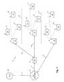
- FIG. 1is a block diagram of an exemplary wireless communication network connected to an overlay network, such as a public switched telephone network (“PSTN”);
- PSTNpublic switched telephone network
- FIG. 2is a block diagram of timing circuitry of a preferred base station
- FIG. 3is a schematic diagram of a preferred adjustable master clock circuit for use in a base or remote station
- FIG. 4is a schematic diagram of another preferred adjustable master clock circuit for use in a base or remote station
- FIG. 5is a block diagram of the timing circuitry of a preferred mobile station
- FIG. 6is a block diagram of a preferred remote station radio interface module
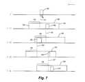
- FIG. 7illustrates a timing window of a preferred mobile station radio interface module.
- an exemplary communication network 10includes a plurality of base stations 12 , which may include one or more intelligent base stations 15 , wherein each base station 12 and intelligent base station 15 is located within a respective geographic cell defined by cell boundaries 13 .
- a plurality of independent (activated) remote stations 14are distributed throughout the network 10 , with multiple remote stations 14 typically located in a particular geographic cell at any given instant.
- the remote stationsmay be mobile handsets or fixed customer premises remote units.
- Both the base stations 12 and intelligent base station 15 and the remote stations 14each preferably comprise a radio transmitter and receiver, and preferably communicate with one another using a combination of time division multiple access (“TDMA”), frequency division multiple access (“FDMA”), and code division multiple access (“CDMA”) transmission techniques, respectively, preferably by employing a spread spectrum encoding format.
- TDMAtime division multiple access
- FDMAfrequency division multiple access
- CDMAcode division multiple access
- TDMAis preferably used to separate users within each geographic cell location.
- FDMAfrequency division multiple access
- CDMAcode division multiple access
- a spread spectrum form of CDMAmay be used for each RF link, (i.e., each over-the-air radio frequency signal link), in order to reduce co-channel interference between nearby cells using the same RF carrier frequency.
- Spread spectrummay advantageously improve system response to RF channel impairments. Both FDD and TDD may be employed with any of these multiple access techniques.
- a base station 12supports the over-the-air, terrestrial, and signaling links, respectively, necessary for linking a remote station 14 to an overlay network 20 , such as, e.g., a public switched telephone network (PSTN) through PCs network infrastructure 19 via interface 17 .
- PSTNpublic switched telephone network
- a base station 12is connected, via back haul lines 18 , to a respective base station controller (“BSC”) 16 , which preferably controls the two-way transmissions of a plurality of base stations 12 in order to more efficiently provide certain operations such as, e.g., call handoffs between base stations and bearer data encoding and decoding, as well as general OAM&P (“operations, administration, maintenance & provisioning”) support functions.
- BSCbase station controller
- An intelligent base station 15is intended herein to describe a base station which incorporates the features of both a standard base station 12 and a base station controller 16 , respectively, in a single unit.
- the respective base station controllers 16 and intelligent base stations 15are connected to the overlay network 20 via further back haul lines 21 .
- an overlay network 20will be connected to a multitude of base stations 12 , either by way of a (smaller) number of base station controllers 16 or directly, where intelligent base stations 15 are employed.
- the respective back haul lines 18 and 21are preferably dedicated (e.g., private or leased public), two-way DS 0 , DS 1 or DS 3 level facilities, depending on the particular traffic load requirements of the specific portion of the communication network 10 .
- each base station 12 and intelligent base station 15preferably employs an over the air loop comprising a number of individual air channels, or time slots, wherein each time slot may be used by a remote station 14 to communicate with the respective base station 12 and intelligent base station 15 .
- an FDD protocolsuch as that embodied in the GSM standards may be employed.
- a time division duplexing (“TDD”) transmission mode techniqueis preferably employed, whereby both downlink—i.e., in the base station to remote station transmission direction—and uplink—i.e., in the remote station to base station transmission direction—transmissions are carried over a common communication frequency path by employing time intervals for each respective signal transmission within a given time slot.
- TDDtime division duplexing
- the 20 ms over the air loopis equally divided between 32 full duplex channels, with each resulting time slot channel being capable of supporting 8 kbps full duplex digital data transmission between the respective base and remote stations.
- McpsMega “chip” per second
- a 20 ms over the air loopis equally divided between 16 full duplex channels, with each resulting time slot channel being capable of supporting 9.6 kbps full duplex transmission between the respective base and remote stations.
- the first portion of each time slot channelis preferably allocated for a remote frame transmission, and the second portion is preferably allocated for a base station frame transmission, respectively.
- a portion of the time slotis preferably allocated to allow sufficient guard time for the transmitted signal to propagate back and forth to the respective receiver, e.g., based on the projected maximum geographic cell radius. In other words, even if there were perfect synchronization between respective base and remote station transmission intervals, a guard time is still preferred to minimize the possibility of received and transmitted signals overlapping in time due to the varying transmission distances and atmospheric conditions within the geographic cell location.
- any time slot in an over the air loop of a given base station 12 and intelligent base station 15 that is not already seized by a remote station 14may contain a general poll command message transmitted by the respective base station 12 and intelligent base station 15 in that time slot's base station transmit interval.
- a remote station 14responds to a received general poll message in a remote station transmit interval.
- the respective base station 12 and intelligent base station 15may send specific poll messages in the next appearance of the same time slot in the over the air loop, which may preferably include a time slot (or time slots) assignment for communication between a remote station 14 and the base station 12 and intelligent base station 15 , which may or may not be the same time slot used to transmit the general poll command message.
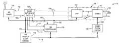
- a preferred base station 12includes a T 1 interface module 30 , which transmits and receives downlink and uplink digital data streams, respectively, and timing information from the network, to and from a respective base station controller 16 via T 1 backhaul lines 18 .
- the interface module 30may be configured to support differing types of transmission rates or formats, such as, e.g., “E 1 ”, depending upon the employed network transmission protocol.
- the downlink and uplink digital data streamsare transmitted to and from the T 1 interface module 30 in a time-division multiplexed format, preferably in sequentially allocated over the air loop frames.
- each over the air loop framecomprises individual data channels, wherein each data channel contains a data frame corresponding to a respective time slot of the base station's over the air loop.
- a data framecomprising 192 bits of bearer data may be transmitted and received, respectively, during each time slot of the respective over the air loop.
- the bearer informationbetween 64 and 128 bits of signaling and control information may be included in each frame transmitted between the base station controller 16 and base station 12 , respectively.
- sync bitsare included in the signaling and control information for synchronizing the vocoders end to end as described in U.S. Pat. No. 5,781,593, which is incorporated herein by reference.
- a duplex data bus 32preferably transmits the respective downlink and uplink information between the T 1 interface module 30 and a radio interface module 34 , respectively.
- the radio interface module 34preferably includes a plurality of downlink and uplink data channel buffers for transitorily storing the data frame contained in each respective channel of one or more over the air loop frames, respectively, on an individual channel-by-channel or frame by frame, basis.
- each over the air loop frame received over bus 32 from the T 1 interface module 30is parsed by the radio interface module 34 into respective downlink data channel buffers.
- Any signaling and/or control information not required for over-the-air transmissionis preferably stripped off the data contained in each respective channel buffer, with the remaining bearer data frame in each respective channel sequentially transmitted over radio interface 36 and into radio 38 , which transmits the information over-the-air preferably on a time slot by time slot basis, respectively, in accordance with the base station's over the air loop timing protocol.
- incoming data frames received by the base station from respective remote stations during the remote station transmit periods of the over the air loopare sequentially loaded into respective uplink channel buffers.
- the requisite signaling and control information for uplink backhaul transmissionis then preferably added to the data frame in each respective uplink channel buffer and the successive data frames are sequentially moved from the radio interface module 34 over bus 32 to the T 1 interface module 30 , preferably forming a backhaul data frame for each respective over the air loop.
- the base station 12is provided with an adjustable base station master clock circuit 40 , which generates a base station clock signal 42 for controlling the timing of the base station 12 , e.g., at a frequency of 20 MHZ in a preferred embodiment for controlling a base station over the air loop of 20 ms.
- the timing control link 46transmits only timing control to the T 1 interface module 30 , both the 20 megahertz clock signal and timing control signals to the radio interface module 34 and only the 20 megahertz clock signal to the radio 38 .
- the timing control signals to the T 1 interface modulecomprises an interrupt signal that indicates that the data transmission for a particular slot is complete.
- the timing control signals sent to the radio interface module 34comprise a transmit enable signal and an over the air loop strobe indicating the beginning of the over the air loop.
- the radio interface module 34sends transmit and receive enable signals.
- the base station clock signal 42is input to base station controller 44 .
- the base station controllercontrols the data frame timing of the T 1 interface module 30 , radio interface module 34 , and radio 38 , respectively, over a timing control link 46 .
- the base station controller 44employs an internal counter for counting successive rising edges of the base station clock signal 42 , to regulate data frame transmission and reception intervals of the base station's over the air loop.
- the master base station clock circuit 40produces a 20 MHZ clock signal 42 , which is input into the base station controller 44 .
- the base station controller's internal counterdetects rising edges of the 20 MHZ clock signal 42 , and outputs data frame control signals over control link 46 for each time slot which, among other things, are used to trigger an incremental data frame transfer by the T 1 module 30 , radio interface module 34 and radio 38 , respectively.
- Each base station 12 of the preferred communication network 10is preferably equipped with a global positioning system (“GPS”) receiver 48 , which delivers an accurate timing pulse 50 transmitted by a GPS satellite once every second.
- GPSglobal positioning system
- the base station controller 44determines whether the internal counter needs adjustment based upon the receipt of the timing pulse as related to a series of overlapping timing windows. If the timing pulse is received during a “no adjust” window, no adjustment is made. If the timing pulse falls outside the “no adjust” window but within a fine adjust window, the internal counter is incremented or decremented by one count. If the timing pulse falls outside the fine adjust window but within a coarse adjust window, the counter is incremented or decremented by multiple counts, preferably 3 to five counts. If it falls outside the coarse adjustment window the counter is reset to an initialized state.
- GPSglobal positioning system
- each base station 12is thereby monitored every second, —e.g., every 50 over the air loop frame periods based on a preferred frame timing of 20 ms, depending on the accuracy of the GPS signal received at the various base station locations and the particular accuracy of the respective base station master clock circuits 40 within each one second interval. Based on the expected accuracy of known circuit elements, monitoring of the synchronization, and adjustment if necessary, every second, will minimize, if not eliminate, any problems arising from cross-transmission interference between base and remote stations in adjacent cells, which could otherwise occur by the drifting apart of their respective clock signals.
- a first exemplary preferred embodiment 40 a of a master base station clock circuitgenerally comprises a clock signal generation module 54 and a phase lock loop module 55 , respectively.
- the clock signal generation module 54includes a voltage sensitive oscillating crystal 56 , preferably having a sufficiently high frequency to ensure an accurate timing pulse—e.g., a 20 MHZ oscillator is preferred for deriving a clock signal 42 of sufficient accuracy for controlling a 20 ms over the air loop frame.
- the signal 58 input to the clock signal generation module 54is connected to the oscillator 56 and to ground through capacitor 60 .
- the other terminal of the oscillating crystal 56is connected to ground through a second capacitor 62 .
- a resistor 64 and inverter 66are arranged in parallel with the oscillator 56 .
- the resulting base station clock signal 42is fed back into the feedback-adjustment module 55 .
- the phase lock loop module 55includes a first dividing circuit 70 , which divides the clock signal 42 into a substantially lower frequency component square wave signal 72 , e.g., 4 KHz in a preferred embodiment.
- the phase lock loop module 55receives an input reference clock signal 52 derived from the overlay network 20 at the T 1 interface module 30 , such as, e.g., an 8 KHz signal derived from the incoming T 1 serial data rate over backhaul lines 18 .
- the network reference clock signal 52is fed into a second dividing circuit 74 , which divides the network reference clock signal 52 into lower frequency component square wave signal 76 having the same frequency, e.g., 4 KHz, as the square wave component signal 72 derived from the base station clock signal 42 .
- the two component square wave signals 72 and 76are then compared to one another, e.g., in a digital X'OR phase detector 78 , to obtain a differential comparison signal 80 , representing the frequency/phase difference between the square wave 72 derived from the base station clock signal 42 and the square wave 76 derived from the network reference clock signal 52 , respectively.
- the differential comparison signal 80is shaped into an analog signal by a pair of RC circuits 82 / 86 and 84 / 88 , respectively, and used as an input to a varactor tuning circuit 90 .
- the varactor tuning circuitproduces a responsive analog feedback voltage 92 corresponding directly to the signal level of the differential comparison signal 80 .
- the feedback voltage 92is coupled to an input 58 of the clock generation module 54 by a capacitor 94 .
- the time constant of the varactor tuning circuit 90is slow to prevent noise on the clock signal in that it slowly updates the master clock frequency.
- a second preferred embodiment 40 b of the master base station clock circuitgenerally comprises a clock signal generation module 96 and a phase lock loop module 97 , respectively.
- the clock signal generation module 96employs a Texas Instruments model LS628 voltage controlled oscillator (“VCO”) 98 , which outputs a base station master clock signal 42 over an output pin 8 , preferably having a sufficiently high frequency (e.g., 20 MHZ) for accurately controlling a 20 ms base station over the air loop.
- VCOvoltage controlled oscillator
- the base station clock signal 42is generated by the VCO 98 by the following preferred input configuration:
- a reference voltage V rfrom a source 100 is connected across an inductor 102 and input, via a first node “A”, into VCO 98 input voltage pin 1 .
- Node “A”is also connected to ground across a capacitor 104 .
- the reference voltage V ris also connected, via a pair of additional nodes “B” and “C”, respectively, across a resistor 108 and input into VCO 98 input voltage pin 3 .
- Node “B”is also connected to ground across a capacitor 106
- node “C”is connected to ground across a resistor 110 , respectively.
- a resistor 112is connected across pins 4 and 5
- a capacitor 114is connected across pins 6 and 7 , respectively, of the VCO 98 .
- the resulting base station clock signal 42 of clock circuit 40 bis fed back into the phase lock loop module 97 .
- the phase lock loop module 97includes a first dividing circuit 124 , which divides the clock signal 42 into a substantially lower frequency component square wave signal 126 , e.g., 4 KHz in a preferred embodiment.
- the feedback module 97also receives an input reference clock signal 52 derived from the overlay network 20 at the T 1 interface module 30 , such as, e.g., an 8 KHz signal derived from the serial data rate of the incoming T 1 signals carried over backhaul lines 18 .
- the network reference clock signal 52is fed into a second dividing circuit 128 , which divides the network reference clock signal 52 into lower frequency component square wave signal 130 having the same frequency (e.g., 4 KHz) as the square wave component signal 126 derived from the base station clock signal 42 .
- the two component square wave signals 126 and 130are then compared to one another, e.g., by a digital X'OR phase detector 132 , to obtain a differential comparison signal 134 , representing the phase differences between the square wave 126 derived from the base station clock signal 42 and the square wave 130 derived from the network reference clock signal 52 , respectively.
- the differential comparison signal 134is then passed through a pair of resistors 136 and 138 , wherein a node “D” located between resistors 136 and 138 is also connected to ground through a resistor 140 and capacitor 142 , respectively.
- the resulting signal 146is connected, via node “E”, to VCO 98 voltage input pin 2 .
- Node “E”is also connected to ground through a capacitor 144 .
- a preferred mobile station 14includes a radio 150 for transmitting and receiving over-the-air (OTA) signals preferably in the form of RF modulated digital data frames to and from respective base stations 12 .
- the radio 150is linked via a parallel receive data bus 152 and a serial transmit interface 152 a to a radio interface module 154 , which includes digital data filter and correlation circuitry for handling incoming data frames received from a base station 12 .
- the radio interface module 154is linked via a full duplex serial interface 156 to a mobile station vocoder module 158 , which includes a digital signal processing (“DSP”) unit 160 and a voice code-decode (“CODEC”) unit 162 , respectively.
- DSPdigital signal processing
- CODECvoice code-decode
- the CODEC unit 162transmits and receives digitally sampled voice signals at 8 KHz (i.e., every 125 micro-seconds), over a two-way voice path 164 and outputs and receives an analog voice signal on lines 165 and 165 a.
- the DSP unit 160performs the requisite data handling of the respective incoming and outgoing data frames, including necessary compression and decompression of the incoming information.
- the mobile station 14is provided with an adjustable mobile station master clock circuit 174 , which generates a mobile station clock signal 176 having the same frequency as the respective base stations 12 of the communication network 10 for controlling the timing of the respective mobile station 14 data transmission operations.
- the mobile station master clock circuit 174is preferably configured substantially identical to the base station master clock circuit 40 , e.g., as depicted in FIGS. 3 and 4, except that its output frequency is adjusted by a pulse width modulator 172 (depicted in FIG. 6) based upon successive incoming base station transmissions, which generates a pulse width modulated control signal 175 .
- the mobile station clock signal 176is used as an input clock for remote station controller 178 .
- the remote station controller 178employs a timing counter for counting successive rising edges of the mobile station clock signal 176 , which information is used to regulate the transmit and receive timing periods of the mobile station 14 within one or more acquired base station 12 time slots.
- the remote station controller 178controls the data transmission timing of the DSP unit 160 , radio interface module 154 , and radio 150 , respectively, through control signals transmitted over a timing control link 180 , which signals include the output of the timing counter in the mobile station controller.
- the mobile station master clock signal 176is also used as a reference clock for synchronizing an adjustable CODEC clock circuit 182 .
- a preferred mobile station 14 employing a 20 MHZ master clock 174 to control the mobile station data transmission operations in a 20 ms over the air loopalso employs a 24.576 MHZ or other even multiple clock 182 to derive a stable 2.048 MHZ CODEC timing signal 184 for controlling 8 KHz digital voice sampling operations.
- the CODEC clock circuit 182is preferably configured substantially identical to the base station master clock circuit 40 , e.g., as depicted in FIGS.
- the synchronization of the CODEC clock timing signal 184 to the mobile station clock signal 176is preferably performed by first dividing each of the respective signals into a (much lower) common frequency square wave component signal, e.g., 4 KHz. The respective 4 KHz square waves are then compared and the output frequency of the CODEC clock circuit 182 is adjusted accordingly. In this way the mobile station CODEC frequency may be locked to the mobile station's master clock frequency, even though the two clocks output different frequency signals.
- a mobile station 14 seeking to initiate contact with a base station 12begins searching over-the-air transmissions for a general polling signal sent by a base station 12 within transmission range of the mobile station 14 .
- the remote station 14analyzes incoming signals received by its radio 150 to find a respective base station general polling signal.
- the first n bits of a received signalare serially loaded into a digital matched filter circuit 165 in the radio interface module 154 , where n corresponds to a selected length of a proprietary base station preamble.
- the n bits of dataare then compared against one or more stored preamble bit-patterns in the matched filter circuit 165 , while the remaining m bits of the received data transmission are loaded into many, preferably 32, serial digital correlators 166 .
- the matched filter circuit 165produces a timing pulse 167 , which substantially corresponds to a known position of the respective transmitting base station's frame counter.
- the timing pulsecauses the serial correlators 166 to extract the received m-bits of data comprising the base station's general polling signal frame, which is preferably checked for accuracy—e.g., by employing a known error-check methodology such as a CRC process 168 —and, if the received data frame is correct within a selected margin of error, a CRC verification signal 173 is input to the early/late detector 170 and the mobile station controller 178 .
- the early/late detector 170compares the output of the mobile station controller 178 timing counter appearing on link 180 to generate an adjustment signal 171 which is input to the pulse width modulator 172 and the mobile station controller 178 .
- the mobile station controller 178sets its timing counter to an initialized state. In this manner, the mobile station controller 178 is synchronized with the over the air loop timing of the respective transmitting base station.
- the pulse width modulated control signal 175is input to the mobile station master clock circuit 174 .
- the remote station controller 178establishes an initial timing window 188 for the serial correlator 166 to receive a specific poll message 190 from the respective base station, preferably in the base station transmit portion of the same over the air loop time slot in which the general polling signal was received.
- the timing window 188preferably has a fixed length of sufficient duration to allow for receiving the expected base station specific poll transmission 190 in the expected time slot interval, while not being so long as to extend beyond the guard time in either direction and inadvertently receive spurious transmissions from other base or mobile stations in bordering time slot intervals.
- cell boundaries 192 , 194 for the initial timing window 188are selected based on the leading edge 191 of the initially received general polling frame 186 , which corresponds to the timing pulse 167 .
- the lead cell boundary 192 of the timing window 188is established by subtracting a fixed early arrival zone 196 from the over the air loop timing by the timing counter of the mobile station controller 178 .
- each successive base station data frame transmissionpreferably includes a preamble.
- the matched filter circuit 165continues to produce a timing pulse 167 upon detecting each received preamble.
- Each successive timing pulse 167is input into an early/late comparator circuit 170 , and compared with the expected arrival time based on the timing counter output of the mobile station controller 178 appearing on the link 180 .
- the early/late comparator circuit 170sends an adjustment signal 171 to the mobile station controller 178 , which directly adjusts the timing counter for establishing a subsequent timing window by adding or subtracting one or more clock pulses to the timing count to either accelerate or delay, respectively, the appearance of the next timing window.
- the base station timing pulsesare also used to continually adjust the output frequency of the mobile station master clock circuit 174 .
- the mobile station clock frequencyis controlled in a manner similar to the continual synchronization of the base station master clock circuit 174 to the overlay network 20 .
- the digital input to the varactor control of the crystal oscillator circuitis preferably the pulse width modulated signal 175 whose duty cycle is adjusted by the pulse width modulator 172 based upon the adjustment signal 171 from the early late detector 170 .
- the respective base and mobile station transmissionsare thereby further prevented from encroaching beyond the guard time gaps following each respective time slot transmission interval, as may otherwise occur from a drift in one or both of the respective clock signal frequencies.
- early/late adjustments to the mobile station's controller counter and master clock frequencyare only made based on timing pulses 167 received in base station transmission frames which pass an error check, e.g., upon receiving a “CRC” verification signal 173 , to ensure no false adjustments are made.
- An advantage of the aforedescribed preferred embodimentis that the mobile station master clock circuit 174 need only be initially accurate enough to detect an initial preamble match and perform a successful CRC routine.
- the respective base station and mobile station clocksare locked by the aforedescribed synchronization adjustments. If a mobile station 14 stops receiving transmissions from the respective base station 12 in the acquired, or later assigned time slot, the mobile station master clock 174 is no longer adjusted and thereafter remains at its last setting until communication with the same, or another base station 12 takes place.
- the disclosed synchronization methods and network architecturescould be employed in a burst-mode data packet transmission network, wherein recovery of, and ongoing synchronization to, an underlying TDMA data cell transmission clock is required on the receiving end of a transmission link.
Landscapes
- Engineering & Computer Science (AREA)
- Computer Networks & Wireless Communication (AREA)
- Signal Processing (AREA)
- Mobile Radio Communication Systems (AREA)
Abstract
Description
Claims (2)
Priority Applications (1)
| Application Number | Priority Date | Filing Date | Title |
|---|---|---|---|
| US09/838,006US6621813B2 (en) | 1996-11-14 | 2001-04-18 | Methods and apparatus for synchronization in a wireless network |
Applications Claiming Priority (2)
| Application Number | Priority Date | Filing Date | Title |
|---|---|---|---|
| US08/749,105US6243372B1 (en) | 1996-11-14 | 1996-11-14 | Methods and apparatus for synchronization in a wireless network |
| US09/838,006US6621813B2 (en) | 1996-11-14 | 2001-04-18 | Methods and apparatus for synchronization in a wireless network |
Related Parent Applications (1)
| Application Number | Title | Priority Date | Filing Date |
|---|---|---|---|
| US08/749,105ContinuationUS6243372B1 (en) | 1996-11-14 | 1996-11-14 | Methods and apparatus for synchronization in a wireless network |
Publications (2)
| Publication Number | Publication Date |
|---|---|
| US20020001299A1 US20020001299A1 (en) | 2002-01-03 |
| US6621813B2true US6621813B2 (en) | 2003-09-16 |
Family
ID=25012279
Family Applications (2)
| Application Number | Title | Priority Date | Filing Date |
|---|---|---|---|
| US08/749,105Expired - LifetimeUS6243372B1 (en) | 1996-11-14 | 1996-11-14 | Methods and apparatus for synchronization in a wireless network |
| US09/838,006Expired - LifetimeUS6621813B2 (en) | 1996-11-14 | 2001-04-18 | Methods and apparatus for synchronization in a wireless network |
Family Applications Before (1)
| Application Number | Title | Priority Date | Filing Date |
|---|---|---|---|
| US08/749,105Expired - LifetimeUS6243372B1 (en) | 1996-11-14 | 1996-11-14 | Methods and apparatus for synchronization in a wireless network |
Country Status (4)
| Country | Link |
|---|---|
| US (2) | US6243372B1 (en) |
| AR (1) | AR010571A1 (en) |
| AU (1) | AU7182698A (en) |
| WO (1) | WO1998021897A2 (en) |
Cited By (16)
| Publication number | Priority date | Publication date | Assignee | Title |
|---|---|---|---|---|
| US20020167934A1 (en)* | 2001-03-09 | 2002-11-14 | Carter Stephen S. | Method and system for timebase synchronization |
| US20030169705A1 (en)* | 2002-03-05 | 2003-09-11 | Knisely Douglas N. | Method for cell switching in wireless communication systems |
| US20040097249A1 (en)* | 2002-11-14 | 2004-05-20 | Manohar Bollapragada V.J. | Method and apparatus for determining an arrival time associated with a synchronization burst |
| US20040121806A1 (en)* | 2002-12-12 | 2004-06-24 | Nec Corporation | Mobile communications system, radio base station control system, and radio base station control method |
| US6765917B1 (en)* | 1998-07-27 | 2004-07-20 | Alcatel Canada Inc. | DS-0 synchronization over a wireless ATM link |
| US20040213367A1 (en)* | 2003-04-25 | 2004-10-28 | Choel-Hee Han | Synchronizing satellite clock in base transceiver station |
| US20060067451A1 (en)* | 2004-09-30 | 2006-03-30 | Pollman Michael D | Providing global positioning system timing signals to remote cellular base stations |
| US20080240163A1 (en)* | 2007-04-02 | 2008-10-02 | Texas Instruments Incorporated | System and method for maintaining transmission synchrony |
| US20080240072A1 (en)* | 2006-03-06 | 2008-10-02 | Vladimir Bykovnikov | Method and Apparatus For Synchronization of Base Stations in a Broadband Wireless Access System |
| US20100310028A1 (en)* | 2006-08-07 | 2010-12-09 | Detwiler Thomas F | Remote Monitoring and Calibration of System Reference Clock Using Network Timing Reference |
| US8364185B2 (en)* | 2005-04-18 | 2013-01-29 | Samsung Electronics Co., Ltd. | Method and system for synchronizing a clock for an adjacent network to a clock for an overlay network |
| US11494320B2 (en)* | 2018-09-24 | 2022-11-08 | Intel Corporation | Delayed link compression scheme |
| US11943045B2 (en) | 2015-10-22 | 2024-03-26 | Commscope Technologies Llc | Virtualization and orchestration of a radio access network |
| US11985615B2 (en) | 2016-07-18 | 2024-05-14 | Commscope Technologies Llc | Synchronization of radio units in radio access networks |
| US12016084B2 (en) | 2018-01-04 | 2024-06-18 | Commscope Technologies Llc | Management of a split physical layer in a radio area network |
| US12021672B2 (en) | 2015-03-11 | 2024-06-25 | Commscope Technologies Llc | Remote radio unit using adaptive compression in a distributed radio access network |
Families Citing this family (134)
| Publication number | Priority date | Publication date | Assignee | Title |
|---|---|---|---|---|
| US6418324B1 (en)* | 1995-06-01 | 2002-07-09 | Padcom, Incorporated | Apparatus and method for transparent wireless communication between a remote device and host system |
| US6243372B1 (en)* | 1996-11-14 | 2001-06-05 | Omnipoint Corporation | Methods and apparatus for synchronization in a wireless network |
| FR2760920B1 (en)* | 1997-03-12 | 2000-08-04 | Sagem | METHOD FOR TRANSMITTING DATA BETWEEN DATA PROCESSING MEANS AND A RADIO COMMUNICATION NETWORK AND MOBILE MODULE AND TERMINAL FOR IMPLEMENTING THE METHOD |
| SE509836C2 (en)* | 1997-06-13 | 1999-03-15 | Ericsson Telefon Ab L M | Procedure and arrangement in a radio communication system |
| US6081536A (en)* | 1997-06-20 | 2000-06-27 | Tantivy Communications, Inc. | Dynamic bandwidth allocation to transmit a wireless protocol across a code division multiple access (CDMA) radio link |
| US6151332A (en) | 1997-06-20 | 2000-11-21 | Tantivy Communications, Inc. | Protocol conversion and bandwidth reduction technique providing multiple nB+D ISDN basic rate interface links over a wireless code division multiple access communication system |
| US6542481B2 (en) | 1998-06-01 | 2003-04-01 | Tantivy Communications, Inc. | Dynamic bandwidth allocation for multiple access communication using session queues |
| JPH1174992A (en)* | 1997-06-23 | 1999-03-16 | Canon Inc | Wireless communication device |
| GB9716626D0 (en)* | 1997-08-07 | 1997-10-15 | Philips Electronics Nv | Wireless network |
| US5872774A (en)* | 1997-09-19 | 1999-02-16 | Qualcomm Incorporated | Mobile station assisted timing synchronization in a CDMA communication system |
| US7936728B2 (en) | 1997-12-17 | 2011-05-03 | Tantivy Communications, Inc. | System and method for maintaining timing of synchronization messages over a reverse link of a CDMA wireless communication system |
| US6222832B1 (en) | 1998-06-01 | 2001-04-24 | Tantivy Communications, Inc. | Fast Acquisition of traffic channels for a highly variable data rate reverse link of a CDMA wireless communication system |
| US7496072B2 (en) | 1997-12-17 | 2009-02-24 | Interdigital Technology Corporation | System and method for controlling signal strength over a reverse link of a CDMA wireless communication system |
| US9525923B2 (en) | 1997-12-17 | 2016-12-20 | Intel Corporation | Multi-detection of heartbeat to reduce error probability |
| US20040160910A1 (en)* | 1997-12-17 | 2004-08-19 | Tantivy Communications, Inc. | Dynamic bandwidth allocation to transmit a wireless protocol across a code division multiple access (CDMA) radio link |
| US8175120B2 (en) | 2000-02-07 | 2012-05-08 | Ipr Licensing, Inc. | Minimal maintenance link to support synchronization |
| US7394791B2 (en) | 1997-12-17 | 2008-07-01 | Interdigital Technology Corporation | Multi-detection of heartbeat to reduce error probability |
| WO1999034638A1 (en)* | 1997-12-23 | 1999-07-08 | Nokia Networks Oy | Clock generating method and apparatus for an asynchronous transmission |
| US7221664B2 (en)* | 1998-06-01 | 2007-05-22 | Interdigital Technology Corporation | Transmittal of heartbeat signal at a lower level than heartbeat request |
| US8134980B2 (en) | 1998-06-01 | 2012-03-13 | Ipr Licensing, Inc. | Transmittal of heartbeat signal at a lower level than heartbeat request |
| US7773566B2 (en) | 1998-06-01 | 2010-08-10 | Tantivy Communications, Inc. | System and method for maintaining timing of synchronization messages over a reverse link of a CDMA wireless communication system |
| EP0963133A1 (en)* | 1998-06-02 | 1999-12-08 | Alcatel | Method and arrangement for transmission of data in a mobile network |
| JPH11355277A (en)* | 1998-06-11 | 1999-12-24 | Canon Inc | Wireless data communication system and wireless data communication method |
| US6470057B1 (en)* | 1998-10-09 | 2002-10-22 | Cwill Telecommunications, Inc. | Method for timing recovery and compensation in time-division-duplex wireless communications |
| JP3850151B2 (en)* | 1998-10-20 | 2006-11-29 | 富士通株式会社 | Wireless base station reception synchronization protection setting method |
| US6556638B1 (en)* | 1999-02-22 | 2003-04-29 | Godigital Networks Corporation | Method and apparatus for providing increased data speed using synchronization and bit robbing techniques |
| FR2790888B1 (en)* | 1999-03-11 | 2003-04-25 | Agence Spatiale Europeenne | SYNCHRONIZATION PROCESS BETWEEN A REFERENCE CLOCK FROM A GROUND STATION AND A CLOCK FROM AT LEAST ONE REMOTE DEVICE |
| US6614776B1 (en)* | 1999-04-28 | 2003-09-02 | Tantivy Communications, Inc. | Forward error correction scheme for high rate data exchange in a wireless system |
| US6452962B1 (en)* | 1999-06-11 | 2002-09-17 | Trw Inc. | Mitigation of co-channel interference in synchronization bursts in a multi-beam communication system |
| US6490689B1 (en)* | 1999-06-21 | 2002-12-03 | International Business Machines Corporation | Managing instruction execution in order to accommodate a physical clock value in a clock representation |
| US7023833B1 (en)* | 1999-09-10 | 2006-04-04 | Pulse-Link, Inc. | Baseband wireless network for isochronous communication |
| US20040090983A1 (en)* | 1999-09-10 | 2004-05-13 | Gehring Stephan W. | Apparatus and method for managing variable-sized data slots within a time division multiple access frame |
| US6526034B1 (en) | 1999-09-21 | 2003-02-25 | Tantivy Communications, Inc. | Dual mode subscriber unit for short range, high rate and long range, lower rate data communications |
| US8463231B1 (en) | 1999-11-02 | 2013-06-11 | Nvidia Corporation | Use of radius in UMTS to perform accounting functions |
| US6873609B1 (en) | 1999-11-02 | 2005-03-29 | Ipwireless, Inc. | Use of internet WEB technology for wireless internet access |
| US6865169B1 (en)* | 1999-11-02 | 2005-03-08 | Ipwireless, Inc. | Cellular wireless internet access system using spread spectrum and internet protocol |
| US8117291B1 (en) | 1999-11-02 | 2012-02-14 | Wireless Technology Solutions Llc | Use of internet web technology to register wireless access customers |
| US7088795B1 (en)* | 1999-11-03 | 2006-08-08 | Pulse-Link, Inc. | Ultra wide band base band receiver |
| US7047000B1 (en)* | 1999-11-26 | 2006-05-16 | Nokia Corporation | Frame error identification |
| US8463255B2 (en)* | 1999-12-20 | 2013-06-11 | Ipr Licensing, Inc. | Method and apparatus for a spectrally compliant cellular communication system |
| FR2803703A1 (en)* | 2000-01-11 | 2001-07-13 | Koninkl Philips Electronics Nv | SYNCHRONIZATION OF A RECEIVER WITH A TRANSMISSION STATION IN A TDMA-TYPE TELECOMMUNICATIONS SYSTEM |
| US7047011B1 (en)* | 2000-02-10 | 2006-05-16 | Telefonaktiebolaget Lm Ericsson (Publ) | Synchronization in diversity handover |
| DE10024153A1 (en)* | 2000-05-19 | 2001-11-22 | Philips Corp Intellectual Pty | Wireless network with capacity measurement has controller using channel associated with terminal to send instruction to transmit more data packets when level threshold exceeded |
| US6970448B1 (en)* | 2000-06-21 | 2005-11-29 | Pulse-Link, Inc. | Wireless TDMA system and method for network communications |
| JP3656526B2 (en)* | 2000-07-17 | 2005-06-08 | 株式会社日立製作所 | Wireless communication base station, wireless position measuring system, transmission timing measuring device, and position measuring center device |
| US7362740B2 (en)* | 2000-09-12 | 2008-04-22 | Timegalactic Ab | Arrangement with a number of units that can communicate with each other via a wireless connection system and a method for use with such a system |
| US6760599B1 (en)* | 2000-09-29 | 2004-07-06 | Arraycomm, Inc. | Method and apparatus for selecting a base station |
| AUPR048500A0 (en)* | 2000-10-02 | 2000-10-26 | Nec Australia Pty Ltd | Radio frequency communications |
| US6438367B1 (en)* | 2000-11-09 | 2002-08-20 | Magis Networks, Inc. | Transmission security for wireless communications |
| US6898212B1 (en)* | 2000-11-14 | 2005-05-24 | Telefonaktiebolaget Lm Ericsson (Publ) | Systems and methods for controlling audible speech distortion in a GPS-based CDMA wireless network using ATM transport |
| WO2002041530A1 (en)* | 2000-11-16 | 2002-05-23 | Sony Corporation | Information processing apparatus and communication apparatus |
| US8155096B1 (en) | 2000-12-01 | 2012-04-10 | Ipr Licensing Inc. | Antenna control system and method |
| US6856945B2 (en) | 2000-12-04 | 2005-02-15 | Tensorcomm, Inc. | Method and apparatus for implementing projections in singal processing applications |
| US6750818B2 (en) | 2000-12-04 | 2004-06-15 | Tensorcomm, Inc. | Method and apparatus to compute the geolocation of a communication device using orthogonal projections |
| US6954448B2 (en) | 2001-02-01 | 2005-10-11 | Ipr Licensing, Inc. | Alternate channel for carrying selected message types |
| US7551663B1 (en) | 2001-02-01 | 2009-06-23 | Ipr Licensing, Inc. | Use of correlation combination to achieve channel detection |
| US6944188B2 (en)* | 2001-02-21 | 2005-09-13 | Wi-Lan, Inc. | Synchronizing clocks across a communication link |
| US7092409B2 (en) | 2001-03-21 | 2006-08-15 | Telefonaktiebolaget Lm Ericsson (Publ) | Timing distribution redundacy in a wireless network |
| CA2867406C (en) | 2001-06-13 | 2016-08-02 | Intel Corporation | Transmittal of heartbeat signal at a lower level than heartbeat request |
| US7158559B2 (en)* | 2002-01-15 | 2007-01-02 | Tensor Comm, Inc. | Serial cancellation receiver design for a coded signal processing engine |
| US8085889B1 (en) | 2005-04-11 | 2011-12-27 | Rambus Inc. | Methods for managing alignment and latency in interference cancellation |
| EP1540860A2 (en) | 2001-11-16 | 2005-06-15 | Tensorcomm Incorporated | Construction of an interference matrix for a coded signal processing engine |
| US7260506B2 (en)* | 2001-11-19 | 2007-08-21 | Tensorcomm, Inc. | Orthogonalization and directional filtering |
| US7039136B2 (en) | 2001-11-19 | 2006-05-02 | Tensorcomm, Inc. | Interference cancellation in a signal |
| JP3877579B2 (en)* | 2001-11-26 | 2007-02-07 | 古野電気株式会社 | TDMA communication device |
| US7813311B2 (en) | 2002-02-05 | 2010-10-12 | Interdigital Technology Corporation | Method and apparatus for synchronizing base stations |
| US6801756B1 (en)* | 2002-02-08 | 2004-10-05 | Networks Associates Technology, Inc. | Method and system for dynamic evaluation of a wireless network with a portable computing device |
| US20030158735A1 (en)* | 2002-02-15 | 2003-08-21 | Canon Kabushiki Kaisha | Information processing apparatus and method with speech synthesis function |
| US7324857B2 (en)* | 2002-04-19 | 2008-01-29 | Gateway Inc. | Method to synchronize playback of multicast audio streams on a local network |
| US7333519B2 (en)* | 2002-04-23 | 2008-02-19 | Gateway Inc. | Method of manually fine tuning audio synchronization of a home network |
| US7392102B2 (en)* | 2002-04-23 | 2008-06-24 | Gateway Inc. | Method of synchronizing the playback of a digital audio broadcast using an audio waveform sample |
| US7209795B2 (en) | 2002-04-23 | 2007-04-24 | Gateway Inc. | Method of synchronizing the playback of a digital audio broadcast by inserting a control track pulse |
| US6691071B2 (en)* | 2002-05-13 | 2004-02-10 | Motorola, Inc. | Synchronizing clock enablement in an electronic device |
| US20040208238A1 (en)* | 2002-06-25 | 2004-10-21 | Thomas John K. | Systems and methods for location estimation in spread spectrum communication systems |
| KR100542039B1 (en)* | 2002-07-02 | 2006-01-10 | 삼성탈레스 주식회사 | Frame Synchronization Signal Generator of Mobile Communication Device |
| US7792089B2 (en)* | 2002-07-31 | 2010-09-07 | Cattron-Theimeg, Inc. | System and method for wireless remote control of locomotives |
| US7369849B2 (en)* | 2002-08-06 | 2008-05-06 | General Motors Corporation | Method and system for registering an in-vehicle cellular phone |
| US20050180364A1 (en)* | 2002-09-20 | 2005-08-18 | Vijay Nagarajan | Construction of projection operators for interference cancellation |
| US7577186B2 (en)* | 2002-09-20 | 2009-08-18 | Tensorcomm, Inc | Interference matrix construction |
| US7463609B2 (en)* | 2005-07-29 | 2008-12-09 | Tensorcomm, Inc | Interference cancellation within wireless transceivers |
| US7876810B2 (en) | 2005-04-07 | 2011-01-25 | Rambus Inc. | Soft weighted interference cancellation for CDMA systems |
| US8761321B2 (en)* | 2005-04-07 | 2014-06-24 | Iii Holdings 1, Llc | Optimal feedback weighting for soft-decision cancellers |
| US7787572B2 (en)* | 2005-04-07 | 2010-08-31 | Rambus Inc. | Advanced signal processors for interference cancellation in baseband receivers |
| US7808937B2 (en) | 2005-04-07 | 2010-10-05 | Rambus, Inc. | Variable interference cancellation technology for CDMA systems |
| US8179946B2 (en)* | 2003-09-23 | 2012-05-15 | Rambus Inc. | Systems and methods for control of advanced receivers |
| EP1550233B1 (en)* | 2002-09-23 | 2012-11-07 | Rambus Inc. | Method and apparatus for selectively applying interference cancellation in spread spectrum systems |
| US20050123080A1 (en)* | 2002-11-15 | 2005-06-09 | Narayan Anand P. | Systems and methods for serial cancellation |
| US8005128B1 (en) | 2003-09-23 | 2011-08-23 | Rambus Inc. | Methods for estimation and interference cancellation for signal processing |
| AU2003301493A1 (en)* | 2002-10-15 | 2004-05-04 | Tensorcomm Inc. | Method and apparatus for interference suppression with efficient matrix inversion in a ds-cdma system |
| EP1579591B1 (en)* | 2002-10-15 | 2012-06-06 | Rambus Inc. | Method and apparatus for channel amplitude estimation and interference vector construction |
| AU2003290558A1 (en)* | 2002-10-31 | 2004-06-07 | Tensorcomm, Incorporated | Systems and methods for reducing interference in cdma systems |
| WO2004073159A2 (en)* | 2002-11-15 | 2004-08-26 | Tensorcomm, Incorporated | Systems and methods for parallel signal cancellation |
| US7339948B2 (en)* | 2003-01-22 | 2008-03-04 | Rockwell Automation Technologies, Inc. | Industrial controller providing deterministic communication on ethernet |
| CN1521967A (en)* | 2003-02-11 | 2004-08-18 | 北京三星通信技术研究有限公司 | Synchronization method for terminal-to-terminal direct communication in time-division multiplexing mobile communication system |
| CN1225849C (en)* | 2003-07-18 | 2005-11-02 | 大唐移动通信设备有限公司 | Method and device for proceeding bidirectional synchronous translate against radio signal |
| US20050041691A1 (en)* | 2003-07-28 | 2005-02-24 | Eli Laufer | Apparatus and methods for providing synchronous digital data transfer over an ethernet |
| US7814188B2 (en)* | 2003-12-16 | 2010-10-12 | Honeywell International Inc. | Synchronized wireless communications system |
| US7523305B2 (en)* | 2003-12-17 | 2009-04-21 | International Business Machines Corporation | Employing cyclic redundancy checks to provide data security |
| US20050169354A1 (en)* | 2004-01-23 | 2005-08-04 | Olson Eric S. | Systems and methods for searching interference canceled data |
| US7477710B2 (en)* | 2004-01-23 | 2009-01-13 | Tensorcomm, Inc | Systems and methods for analog to digital conversion with a signal cancellation system of a receiver |
| US7672268B2 (en)* | 2004-06-18 | 2010-03-02 | Kenneth Stanwood | Systems and methods for implementing double wide channels in a communication system |
| KR101222447B1 (en)* | 2004-07-15 | 2013-01-15 | 큐빅 코포레이션 | Enhancement of aimpoint in simulated training systems |
| US7336572B1 (en)* | 2004-08-19 | 2008-02-26 | Marvell International Ltd. | Detecting sync patterns for optical media |
| US20060125689A1 (en)* | 2004-12-10 | 2006-06-15 | Narayan Anand P | Interference cancellation in a receive diversity system |
| US20060229051A1 (en)* | 2005-04-07 | 2006-10-12 | Narayan Anand P | Interference selection and cancellation for CDMA communications |
| US7826516B2 (en) | 2005-11-15 | 2010-11-02 | Rambus Inc. | Iterative interference canceller for wireless multiple-access systems with multiple receive antennas |
| DE502005009756D1 (en)* | 2005-04-29 | 2010-07-29 | Tektronix Int Sales Gmbh | Timed synchronized measuring system and method for timing synchronization of at least one master and one slave device |
| US7333468B1 (en)* | 2005-05-16 | 2008-02-19 | Sun Microsystems, Inc. | Digital phase locked loops for packet stream rate matching and restamping |
| FR2886793A1 (en)* | 2005-06-06 | 2006-12-08 | France Telecom | METHOD AND SYSTEM FOR TRANSMITTING A SYNCHRONIZATION RHYTHM ON A NETWORK LINK OF ETHERNET TECHNOLOGY AND THEIR APPLICATIONS |
| US7574224B2 (en)* | 2005-06-13 | 2009-08-11 | Qualcomm Incorporated | Methods and apparatus for performing timing synchronization with base stations |
| US7583654B2 (en) | 2005-12-28 | 2009-09-01 | Honeywell International Inc. | Sub-frame synchronized multiplexing |
| US8843086B2 (en)* | 2006-01-31 | 2014-09-23 | Blackberry Limited | Method and apparatus for enabling transmission in a slotted radio data communication system by pausing data reception |
| US7596153B2 (en)* | 2006-10-13 | 2009-09-29 | Honeywell International Inc. | Clock-state correction and/or clock-rate correction using relative drift-rate measurements |
| US20080248800A1 (en)* | 2007-04-05 | 2008-10-09 | Beceem Communications, Inc. | Managing handoffs between overlaid networks |
| US20090129333A1 (en)* | 2007-11-16 | 2009-05-21 | Qualcomm Incorporated | Preamble design for a wireless signal |
| US8918112B2 (en)* | 2007-11-16 | 2014-12-23 | Qualcomm Incorporated | Preamble design for a wireless signal |
| US9264976B2 (en) | 2007-11-16 | 2016-02-16 | Qualcomm Incorporated | Preamble design for a wireless signal |
| US9215669B2 (en)* | 2007-11-16 | 2015-12-15 | Qualcomm Incorporated | Preamble design for a wireless signal |
| GB2454936B (en)* | 2007-11-23 | 2012-09-19 | Ubiquisys Ltd | Oscillator calibration |
| JP4592743B2 (en)* | 2007-12-28 | 2010-12-08 | 古野電気株式会社 | Synchronization device and synchronization method |
| US9801188B2 (en)* | 2008-02-01 | 2017-10-24 | Qualcomm Incorporated | Backhaul signaling for interference avoidance |
| US8768372B2 (en)* | 2008-02-13 | 2014-07-01 | Qualcomm Incorporated | Sector interference management based on inter-sector performance |
| US8867520B2 (en)* | 2008-03-07 | 2014-10-21 | Charles Nicholls | Using a network frequency reference to augment timing Synchronization in a wireless base station |
| US20120082188A2 (en)* | 2008-12-03 | 2012-04-05 | Nortel Networks Limited | Multiple redundant gnss synchronization system |
| US8879585B2 (en)* | 2010-05-13 | 2014-11-04 | Mediatek Inc. | Frame timing controller and frame timing control method for triggering at least receiver in mobile station to start receiving transmitted information of base station by referring to at least frame pointer |
| BR112013003583A2 (en) | 2010-08-26 | 2016-06-07 | Thomson Licensing | use of white space for wireless LAN devices |
| US9515755B2 (en)* | 2011-04-06 | 2016-12-06 | Maxtech Communication Neworks Ltd. | Dynamically self-organizing ad-hoc TDMA communications synchronization method |
| US8958897B2 (en)* | 2012-07-03 | 2015-02-17 | Revo Labs, Inc. | Synchronizing audio signal sampling in a wireless, digital audio conferencing system |
| US9048935B2 (en)* | 2013-01-25 | 2015-06-02 | Alcatel Lucent | Joint synchronization and modulation scheme for energy-efficient communication |
| CN105144831A (en)* | 2013-03-14 | 2015-12-09 | 诺基亚通信公司 | Method and apparatus |
| CN104240710B (en)* | 2013-06-06 | 2019-01-08 | 腾讯科技(深圳)有限公司 | A kind of method, system and the terminal device of information transmission |
| US10708086B2 (en)* | 2016-01-19 | 2020-07-07 | National Instruments Corporation | Channel sounding techniques |
| WO2018018613A1 (en)* | 2016-07-29 | 2018-02-01 | 广东东阳光药业有限公司 | Cell culture medium and culture method for increasing purity of antibody |
| US11075743B2 (en)* | 2019-08-27 | 2021-07-27 | Nxp Usa, Inc. | Adjustable high resolution timer |
Citations (28)
| Publication number | Priority date | Publication date | Assignee | Title |
|---|---|---|---|---|
| US4001693A (en) | 1975-05-12 | 1977-01-04 | General Electric Company | Apparatus for establishing communication between a first radio transmitter and receiver and a second radio transmitter and receiver |
| US4231114A (en) | 1978-02-27 | 1980-10-28 | Motorola, Inc. | Synchronizing means for a two-way communication system |
| US4280222A (en) | 1980-01-14 | 1981-07-21 | The Singer Company | Receiver and correlator switching method |
| US4355388A (en)* | 1979-09-27 | 1982-10-19 | Communications Satellite Corporation | Microprogrammable TDMA terminal controller |
| US4494211A (en) | 1982-11-24 | 1985-01-15 | The United States Of America As Represented By The Secretary Of The Navy | Balanced system for ranging and synchronization between satellite pairs |
| US4513412A (en)* | 1983-04-25 | 1985-04-23 | At&T Bell Laboratories | Time division adaptive retransmission technique for portable radio telephones |
| US4630291A (en) | 1983-05-27 | 1986-12-16 | Compagnie Industrielle Des Telecommunicat. | Externally synchronized timebase |
| US4688210A (en) | 1985-03-29 | 1987-08-18 | U.S. Philips Corporation | Method of and arrangement for synchronizing the receiver arrangements in a digital multiplex transmission system |
| US4696051A (en) | 1985-12-31 | 1987-09-22 | Motorola Inc. | Simulcast transmission system having automtic synchronization |
| US4713631A (en) | 1986-01-06 | 1987-12-15 | Motorola Inc. | Varactor tuning circuit having plural selectable bias voltages |
| US5028885A (en) | 1990-08-30 | 1991-07-02 | Motorola, Inc. | Phase-locked loop signal generation system with control maintenance |
| US5103459A (en) | 1990-06-25 | 1992-04-07 | Qualcomm Incorporated | System and method for generating signal waveforms in a cdma cellular telephone system |
| US5109393A (en) | 1989-07-13 | 1992-04-28 | Nec Corporation | Mobile communications system insensitive to false frame sync |
| US5144669A (en)* | 1987-09-14 | 1992-09-01 | British Telecommunications Public Limited Company | Method of communicating digital signals and receiver for use with such method |
| US5195091A (en) | 1991-07-09 | 1993-03-16 | At&T Bell Laboratories | Adaptive synchronization arrangement |
| US5222075A (en) | 1989-12-29 | 1993-06-22 | Xerox Corporation | Transmitted code clock code-matching synchronization for spread-spectrum communication systems |
| US5239671A (en) | 1990-11-13 | 1993-08-24 | Pagemart, Inc. | Simulcast satellite paging system with provision for signal interruption |
| US5245634A (en) | 1992-03-23 | 1993-09-14 | Motorola, Inc. | Base-site synchronization in a communication system |
| US5353300A (en) | 1993-06-07 | 1994-10-04 | Motorola, Inc. | Communication method for an adaptive direct sequence CDMA communication system |
| US5363373A (en) | 1991-04-30 | 1994-11-08 | Nec Corporation | Digital mobile station using presettable timeslot counter for compensating for propagation delay time |
| US5416800A (en) | 1991-12-07 | 1995-05-16 | U.S. Philips Corporation | Mobile radio receiver for a radio transmission system |
| US5446727A (en) | 1993-11-30 | 1995-08-29 | Motorola Inc. | Method and apparatus for time aligning signals for reception in a code-division multiple access communication system |
| US5481533A (en) | 1994-05-12 | 1996-01-02 | Bell Communications Research, Inc. | Hybrid intra-cell TDMA/inter-cell CDMA for wireless networks |
| US5506863A (en) | 1993-08-25 | 1996-04-09 | Motorola, Inc. | Method and apparatus for operating with a hopping control channel in a communication system |
| US5528597A (en) | 1994-04-18 | 1996-06-18 | At&T Corp. | Autonomous synchronization of base stations in a digital wireless radiotelephone network |
| US5654991A (en)* | 1995-07-31 | 1997-08-05 | Harris Corporation | Fast acquisition bit timing loop method and apparatus |
| US5809397A (en)* | 1996-02-29 | 1998-09-15 | Motorola, Inc. | Method and apparatus for system synchronization in a messaging system |
| US6243372B1 (en)* | 1996-11-14 | 2001-06-05 | Omnipoint Corporation | Methods and apparatus for synchronization in a wireless network |
Family Cites Families (4)
| Publication number | Priority date | Publication date | Assignee | Title |
|---|---|---|---|---|
| US3825899A (en)* | 1971-08-11 | 1974-07-23 | Communications Satellite Corp | Expansion/compression and elastic buffer combination |
| US4849993A (en)* | 1987-12-10 | 1989-07-18 | Silicon General, Inc. | Clock holdover circuit |
| CA2091962A1 (en)* | 1992-03-31 | 1993-10-01 | Mark L. Witsaman | Clock synchronization system |
| US5680414A (en)* | 1994-09-09 | 1997-10-21 | Omnipoint Corporation | Synchronization apparatus and method for spread spectrum receiver |
- 1996
- 1996-11-14USUS08/749,105patent/US6243372B1/ennot_activeExpired - Lifetime
- 1997
- 1997-11-12ARARP970105255Apatent/AR010571A1/enunknown
- 1997-11-13AUAU71826/98Apatent/AU7182698A/ennot_activeAbandoned
- 1997-11-13WOPCT/US1997/020659patent/WO1998021897A2/enactiveApplication Filing
- 2001
- 2001-04-18USUS09/838,006patent/US6621813B2/ennot_activeExpired - Lifetime
Patent Citations (29)
| Publication number | Priority date | Publication date | Assignee | Title |
|---|---|---|---|---|
| US4001693A (en) | 1975-05-12 | 1977-01-04 | General Electric Company | Apparatus for establishing communication between a first radio transmitter and receiver and a second radio transmitter and receiver |
| US4231114A (en) | 1978-02-27 | 1980-10-28 | Motorola, Inc. | Synchronizing means for a two-way communication system |
| US4355388A (en)* | 1979-09-27 | 1982-10-19 | Communications Satellite Corporation | Microprogrammable TDMA terminal controller |
| US4280222A (en) | 1980-01-14 | 1981-07-21 | The Singer Company | Receiver and correlator switching method |
| US4494211A (en) | 1982-11-24 | 1985-01-15 | The United States Of America As Represented By The Secretary Of The Navy | Balanced system for ranging and synchronization between satellite pairs |
| US4513412A (en)* | 1983-04-25 | 1985-04-23 | At&T Bell Laboratories | Time division adaptive retransmission technique for portable radio telephones |
| US4630291A (en) | 1983-05-27 | 1986-12-16 | Compagnie Industrielle Des Telecommunicat. | Externally synchronized timebase |
| US4688210A (en) | 1985-03-29 | 1987-08-18 | U.S. Philips Corporation | Method of and arrangement for synchronizing the receiver arrangements in a digital multiplex transmission system |
| US4696051A (en) | 1985-12-31 | 1987-09-22 | Motorola Inc. | Simulcast transmission system having automtic synchronization |
| US4713631A (en) | 1986-01-06 | 1987-12-15 | Motorola Inc. | Varactor tuning circuit having plural selectable bias voltages |
| US5144669A (en)* | 1987-09-14 | 1992-09-01 | British Telecommunications Public Limited Company | Method of communicating digital signals and receiver for use with such method |
| US5109393A (en) | 1989-07-13 | 1992-04-28 | Nec Corporation | Mobile communications system insensitive to false frame sync |
| US5222075A (en) | 1989-12-29 | 1993-06-22 | Xerox Corporation | Transmitted code clock code-matching synchronization for spread-spectrum communication systems |
| US5103459A (en) | 1990-06-25 | 1992-04-07 | Qualcomm Incorporated | System and method for generating signal waveforms in a cdma cellular telephone system |
| US5103459B1 (en) | 1990-06-25 | 1999-07-06 | Qualcomm Inc | System and method for generating signal waveforms in a cdma cellular telephone system |
| US5028885A (en) | 1990-08-30 | 1991-07-02 | Motorola, Inc. | Phase-locked loop signal generation system with control maintenance |
| US5239671A (en) | 1990-11-13 | 1993-08-24 | Pagemart, Inc. | Simulcast satellite paging system with provision for signal interruption |
| US5363373A (en) | 1991-04-30 | 1994-11-08 | Nec Corporation | Digital mobile station using presettable timeslot counter for compensating for propagation delay time |
| US5195091A (en) | 1991-07-09 | 1993-03-16 | At&T Bell Laboratories | Adaptive synchronization arrangement |
| US5416800A (en) | 1991-12-07 | 1995-05-16 | U.S. Philips Corporation | Mobile radio receiver for a radio transmission system |
| US5245634A (en) | 1992-03-23 | 1993-09-14 | Motorola, Inc. | Base-site synchronization in a communication system |
| US5353300A (en) | 1993-06-07 | 1994-10-04 | Motorola, Inc. | Communication method for an adaptive direct sequence CDMA communication system |
| US5506863A (en) | 1993-08-25 | 1996-04-09 | Motorola, Inc. | Method and apparatus for operating with a hopping control channel in a communication system |
| US5446727A (en) | 1993-11-30 | 1995-08-29 | Motorola Inc. | Method and apparatus for time aligning signals for reception in a code-division multiple access communication system |
| US5528597A (en) | 1994-04-18 | 1996-06-18 | At&T Corp. | Autonomous synchronization of base stations in a digital wireless radiotelephone network |
| US5481533A (en) | 1994-05-12 | 1996-01-02 | Bell Communications Research, Inc. | Hybrid intra-cell TDMA/inter-cell CDMA for wireless networks |
| US5654991A (en)* | 1995-07-31 | 1997-08-05 | Harris Corporation | Fast acquisition bit timing loop method and apparatus |
| US5809397A (en)* | 1996-02-29 | 1998-09-15 | Motorola, Inc. | Method and apparatus for system synchronization in a messaging system |
| US6243372B1 (en)* | 1996-11-14 | 2001-06-05 | Omnipoint Corporation | Methods and apparatus for synchronization in a wireless network |
Non-Patent Citations (3)
| Title |
|---|
| "Air Interface Considerations," Joint Experts Meeting, Rockwell Int'l, Nov. 9, 1992. |
| Omnipoint Corporation-Omnipoint IS-661-Based Composite CMDA/TDMA PCS System Overview-Dated: Jun. 1995. |
| Omnipoint Corporation—Omnipoint IS-661-Based Composite CMDA/TDMA PCS System Overview—Dated: Jun. 1995. |
Cited By (24)
| Publication number | Priority date | Publication date | Assignee | Title |
|---|---|---|---|---|
| US6765917B1 (en)* | 1998-07-27 | 2004-07-20 | Alcatel Canada Inc. | DS-0 synchronization over a wireless ATM link |
| US20020167934A1 (en)* | 2001-03-09 | 2002-11-14 | Carter Stephen S. | Method and system for timebase synchronization |
| US7373175B2 (en)* | 2001-03-09 | 2008-05-13 | Qualcomm Incorporated | Method and apparatus for timebase synchronization for use with cellular base stations |
| US20030169705A1 (en)* | 2002-03-05 | 2003-09-11 | Knisely Douglas N. | Method for cell switching in wireless communication systems |
| US7251228B2 (en)* | 2002-03-05 | 2007-07-31 | Lucent Technologies Inc. | Method for cell switching in wireless communication systems |
| US7447236B2 (en)* | 2002-11-14 | 2008-11-04 | Siemens Aktiengesellschaft | Method and apparatus for determining an arrival time associated with a synchronization burst |
| US20040097249A1 (en)* | 2002-11-14 | 2004-05-20 | Manohar Bollapragada V.J. | Method and apparatus for determining an arrival time associated with a synchronization burst |
| US20040121806A1 (en)* | 2002-12-12 | 2004-06-24 | Nec Corporation | Mobile communications system, radio base station control system, and radio base station control method |
| US7035669B2 (en)* | 2002-12-12 | 2006-04-25 | Nec Corporation | Mobile communications system, radio base station control system, and radio base station control method |
| US20040213367A1 (en)* | 2003-04-25 | 2004-10-28 | Choel-Hee Han | Synchronizing satellite clock in base transceiver station |
| US20060067451A1 (en)* | 2004-09-30 | 2006-03-30 | Pollman Michael D | Providing global positioning system timing signals to remote cellular base stations |
| US7558356B2 (en)* | 2004-09-30 | 2009-07-07 | Airvana, Inc. | Providing global positioning system (GPS) timing signals to remote cellular base stations |
| US8364185B2 (en)* | 2005-04-18 | 2013-01-29 | Samsung Electronics Co., Ltd. | Method and system for synchronizing a clock for an adjacent network to a clock for an overlay network |
| US20080240072A1 (en)* | 2006-03-06 | 2008-10-02 | Vladimir Bykovnikov | Method and Apparatus For Synchronization of Base Stations in a Broadband Wireless Access System |
| US7844289B2 (en)* | 2006-03-06 | 2010-11-30 | Intel Corporation | Method and apparatus for synchronization of base stations in a broadband wireless access system |
| US8670511B2 (en) | 2006-08-07 | 2014-03-11 | Aviat U.S., Inc. | Remote monitoring and calibration of system reference clock using network timing reference |
| US20100310028A1 (en)* | 2006-08-07 | 2010-12-09 | Detwiler Thomas F | Remote Monitoring and Calibration of System Reference Clock Using Network Timing Reference |
| US20080240163A1 (en)* | 2007-04-02 | 2008-10-02 | Texas Instruments Incorporated | System and method for maintaining transmission synchrony |
| US12021672B2 (en) | 2015-03-11 | 2024-06-25 | Commscope Technologies Llc | Remote radio unit using adaptive compression in a distributed radio access network |
| US11943045B2 (en) | 2015-10-22 | 2024-03-26 | Commscope Technologies Llc | Virtualization and orchestration of a radio access network |
| US11985615B2 (en) | 2016-07-18 | 2024-05-14 | Commscope Technologies Llc | Synchronization of radio units in radio access networks |
| US12245176B2 (en) | 2016-07-18 | 2025-03-04 | Commscope Technologies Llc | Device for fronthaul communication between a baseband unit and a remote unit of a radio access network |
| US12016084B2 (en) | 2018-01-04 | 2024-06-18 | Commscope Technologies Llc | Management of a split physical layer in a radio area network |
| US11494320B2 (en)* | 2018-09-24 | 2022-11-08 | Intel Corporation | Delayed link compression scheme |
Also Published As
| Publication number | Publication date |
|---|---|
| AR010571A1 (en) | 2000-06-28 |
| US20020001299A1 (en) | 2002-01-03 |
| WO1998021897A3 (en) | 1998-10-01 |
| US6243372B1 (en) | 2001-06-05 |
| WO1998021897A2 (en) | 1998-05-22 |
| AU7182698A (en) | 1998-06-03 |
Similar Documents
| Publication | Publication Date | Title |
|---|---|---|
| US6621813B2 (en) | Methods and apparatus for synchronization in a wireless network | |
| RU2146420C1 (en) | Method and device for synchronizing burst transmission to communication system | |
| US8675666B2 (en) | Systems and methods for distributing GPS clock to communications device | |
| KR100589934B1 (en) | Synchronization of timing advance and deviation | |
| US5519710A (en) | Network synchronization for TDMA cellular communication using signals from mobile stations in neighboring cells | |
| EP1205041B1 (en) | Frequency synchronization of base station | |
| US5987023A (en) | Transmission timing control in digital radio telephony | |
| US5710765A (en) | Method and apparatus for increasing the system efficiency of a TDMA system by reducing time slot guard time | |
| GB2293706A (en) | Nested digital phase lock loop | |
| US5436937A (en) | Multi-mode digital phase lock loop | |
| EP0860057B1 (en) | Method and apparatus for power control in a telephone system | |
| JP2638295B2 (en) | TDMA digital mobile communication system | |
| US6788947B2 (en) | Method for synchronization of base stations which are coupled to different switching system parts in a mobile radio network | |
| US5781593A (en) | Methods and apparatus for vocoder synchronization in mobile communication network | |
| JPH0923473A (en) | Inter-base station synchronization method | |
| EP1212906B1 (en) | Network frequency setting | |
| JP2526803B2 (en) | Radio base station synchronization method and mobile communication system | |
| JP2731640B2 (en) | TDMA frame synchronization method between multiple radio base stations | |
| JPH03235436A (en) | Mobile communication device | |
| JPH10164651A (en) | Base station equipment for public phs | |
| AU9723598A (en) | Method for increasing the range of a radiocommunications unit |
Legal Events
| Date | Code | Title | Description |
|---|---|---|---|
| AS | Assignment | Owner name:INTEL CORPORATION, CALIFORNIA Free format text:ASSIGNMENT OF ASSIGNORS INTEREST;ASSIGNOR:XIRCOM WIRELESS, INC.;REEL/FRAME:013292/0865 Effective date:20020613 | |
| AS | Assignment | Owner name:INTEL CORPORATION, CALIFORNIA Free format text:ASSIGNMENT OF ASSIGNORS INTEREST;ASSIGNOR:XIRCOM WIRELESS, INC.;REEL/FRAME:013294/0386 Effective date:20020613 | |
| AS | Assignment | Owner name:XIRCOM II WIRELESS, INC., COLORADO Free format text:ASSIGNMENT OF ASSIGNORS INTEREST;ASSIGNOR:INTEL CORPORATION;REEL/FRAME:014327/0157 Effective date:20021227 | |
| AS | Assignment | Owner name:INTEL CORPORATION, CALIFORNIA Free format text:ASSIGNMENT OF ASSIGNORS INTEREST;ASSIGNOR:XIRCOM II WIRELESS, INC.;REEL/FRAME:014420/0537 Effective date:20030821 | |
| STCF | Information on status: patent grant | Free format text:PATENTED CASE | |
| FEPP | Fee payment procedure | Free format text:PAYOR NUMBER ASSIGNED (ORIGINAL EVENT CODE: ASPN); ENTITY STATUS OF PATENT OWNER: LARGE ENTITY | |
| FPAY | Fee payment | Year of fee payment:4 | |
| FPAY | Fee payment | Year of fee payment:8 | |
| FPAY | Fee payment | Year of fee payment:12 |