US6621808B1 - Adaptive power control based on a rake receiver configuration in wideband CDMA cellular systems (WCDMA) and methods of operation - Google Patents
Adaptive power control based on a rake receiver configuration in wideband CDMA cellular systems (WCDMA) and methods of operationDownload PDFInfo
- Publication number
- US6621808B1 US6621808B1US09/413,935US41393599AUS6621808B1US 6621808 B1US6621808 B1US 6621808B1US 41393599 AUS41393599 AUS 41393599AUS 6621808 B1US6621808 B1US 6621808B1
- Authority
- US
- United States
- Prior art keywords
- power
- channel
- transmitter
- receiver
- finger
- Prior art date
- Legal status (The legal status is an assumption and is not a legal conclusion. Google has not performed a legal analysis and makes no representation as to the accuracy of the status listed.)
- Expired - Lifetime
Links
- 238000000034methodMethods0.000titleclaimsdescription28
- 230000003044adaptive effectEffects0.000titledescription18
- 230000001413cellular effectEffects0.000titledescription3
- 230000005540biological transmissionEffects0.000claimsdescription17
- 230000003247decreasing effectEffects0.000claimsdescription3
- 230000008878couplingEffects0.000claims2
- 238000010168coupling processMethods0.000claims2
- 238000005859coupling reactionMethods0.000claims2
- 230000009977dual effectEffects0.000claims1
- 230000011664signalingEffects0.000claims1
- 238000004891communicationMethods0.000abstractdescription13
- 230000010363phase shiftEffects0.000abstractdescription4
- 230000001427coherent effectEffects0.000abstractdescription3
- 230000007480spreadingEffects0.000description13
- 230000008859changeEffects0.000description9
- 238000005562fadingMethods0.000description7
- 238000007726management methodMethods0.000description5
- 230000008569processEffects0.000description5
- 238000012545processingMethods0.000description5
- 108010003272Hyaluronate lyaseProteins0.000description4
- 238000010586diagramMethods0.000description4
- 238000005516engineering processMethods0.000description4
- 238000004364calculation methodMethods0.000description3
- 238000004458analytical methodMethods0.000description2
- 230000008901benefitEffects0.000description2
- 230000007423decreaseEffects0.000description2
- 238000001514detection methodMethods0.000description2
- 238000005315distribution functionMethods0.000description2
- 238000002474experimental methodMethods0.000description2
- 238000001228spectrumMethods0.000description2
- 238000012360testing methodMethods0.000description2
- 230000009471actionEffects0.000description1
- 230000004913activationEffects0.000description1
- 239000008186active pharmaceutical agentSubstances0.000description1
- 239000000654additiveSubstances0.000description1
- 230000000996additive effectEffects0.000description1
- 230000010267cellular communicationEffects0.000description1
- 238000012937correctionMethods0.000description1
- 239000013078crystalSubstances0.000description1
- 230000001419dependent effectEffects0.000description1
- 230000006872improvementEffects0.000description1
- 230000007774longtermEffects0.000description1
- 238000005457optimizationMethods0.000description1
- 230000035945sensitivityEffects0.000description1
- 239000002699waste materialSubstances0.000description1
Images


Classifications
- H—ELECTRICITY
- H04—ELECTRIC COMMUNICATION TECHNIQUE
- H04W—WIRELESS COMMUNICATION NETWORKS
- H04W52/00—Power management, e.g. Transmission Power Control [TPC] or power classes
- H04W52/04—Transmission power control [TPC]
- H04W52/18—TPC being performed according to specific parameters
- H04W52/24—TPC being performed according to specific parameters using SIR [Signal to Interference Ratio] or other wireless path parameters
- H—ELECTRICITY
- H04—ELECTRIC COMMUNICATION TECHNIQUE
- H04B—TRANSMISSION
- H04B1/00—Details of transmission systems, not covered by a single one of groups H04B3/00 - H04B13/00; Details of transmission systems not characterised by the medium used for transmission
- H04B1/69—Spread spectrum techniques
- H04B1/707—Spread spectrum techniques using direct sequence modulation
- H04B1/7097—Interference-related aspects
- H04B1/711—Interference-related aspects the interference being multi-path interference
- H04B1/7115—Constructive combining of multi-path signals, i.e. RAKE receivers
- H—ELECTRICITY
- H04—ELECTRIC COMMUNICATION TECHNIQUE
- H04W—WIRELESS COMMUNICATION NETWORKS
- H04W52/00—Power management, e.g. Transmission Power Control [TPC] or power classes
- H04W52/04—Transmission power control [TPC]
- H04W52/18—TPC being performed according to specific parameters
- H04W52/26—TPC being performed according to specific parameters using transmission rate or quality of service QoS [Quality of Service]
Definitions
- This inventionrelates to communication systems and methods of operation. More particularly, the invention relates to adaptive power management based on a Rake Receiver configuration in WCDMA systems and methods of operation.
- CDMACode-Division Multiple Access
- thresholdsare set based on the probability distribution function (pdf) of the channel power.
- PDFprobability distribution function
- the pdf of the channel powerwould be an exponential or chi-square function with 2 degrees of freedom.
- the rake receivernormally the rake receiver has several fingers. That is at the receiver, the system either estimates or predicts the channel coefficients at each rake finger and performs maximal ratio combining by multiplying each finger with its conjugate or chooses the ones with the highest energy and performs maximal ratio combining on the selected fingers. In either case system performs the long-range power prediction of each finger at the transmitter to compute the total channel power.
- U.S. Pat. No. 5,822,381 to E. Tiedemann, Jr. et al., issued Oct. 13, 1998discloses a method and apparatus for controlling transmission power in a variable rate communication system.
- the method disclosedprovides for a closed loop power control method.
- a first remote stationcontrols the transmission power of a second remote station by transmitting a rate dependent power control signal to the second remote communications system. Since only the second communications system knows its transmission rate a priori, it must determine a course of action in accordance with both the received power control signal and the knowledge of its transmission rate.
- U.S. Pat. No. 5,715,526 to L. A. Weaver, Jr., et al., issued Feb. 3, 1998,discloses an apparatus and method for controlling a final transmit power, Y of a base station in a cellular communications system that has several channels.
- the base stationhas a transmit power tracking gain, Y′ and a radio frequency transmit power, W.
- the apparatuscomprises channel elements for calculating expected power P k,a ⁇ P kf , each of which corresponds to a channel.
- the apparatusalso comprises a transceiver system controller (BTSC) for generating a desired output power, Y d of the base station, including an adder for summing the expected powers.
- BTSCtransceiver system controller
- the apparatusalso includes a transmit power detector for measuring ‘Y’ to obtain the measured transmit power.
- the apparatusfurther comprises a radio frequency interface card (RFIC) for generating ‘Y’.
- RFICradio frequency interface card
- the apparatusincludes a gain unit for processing ‘Y’ and W to obtain the final transmitted power, Y.
- the base stationsends a frame to the mobile at a particular rate. If the mobile received and decoded the frame correctly, the mobile sets a power control bit and the next frame to be transmitted to the base station. Based on the error rate of the received power control bits, the base station determines whether to increase or decrease the transmit power.
- U.S. Pat. No. 5,729,557 to S. H. Gardner, et al, issued Mar. 17, 1998, (Gardner)discloses a method and apparatus for using multiple code rates for forward error correction in a cellular digital radio communication system.
- Each base stationbroadcasts a quantity called the power product (PP) which is equal to the base transmit power, P BT multiplied by the power level received at the base station, P BR .
- PPpower product
- P MTFor a mobile-unit to determine it's appropriate transmit power, P MT requires measuring the power received, P MR at the mobile unit and performing a calculation. When the channel path loss is large it is possible that the power control calculation will return a value greater than the maximum transmit power capability of the mobile unit. In such case, the mobile unit selects a lower code rate.
- the base station receiver sensitivityimproves as the code rate decreases, so the result is similar to increasing the transmit power.
- the inventionuses three different code rates. In most cases, the code rate used is two-thirds, but when a mobile unit determines that it needs more transmit power than it is capable of providing, the code range is changed to one-half, and in severe cases the code rate is changed to one-third.
- JP6-276176 to Tetsuyoshi et al, published Sep. 30, 1994discloses reducing intra-signal interference at the time of demodulating signals from respective remote stations by preparing plural chip rates and appropriately allocating them for the respective remote stations.
- a chip rate deciding circuitjudges that the reception power level causes strong interference and the inverse spread demodulation of the signals.
- the present chip ratein this case is changed and the remote station is informed from a chip rate informing circuit.
- a spreading codeis generated corresponding to the chip rate informed from the base station.
- a spreading codeis generated supplied to a spectrum spread modulation part to perform spread spectrum spread modulation and transmitted to the base station.
- the base stationperforms an inverse spread processing by the chip rate and interference is reduced at the remote stations.
- An object of the inventionis a communication system such as a WCDMA system and method of operation having adaptive modulation for improved system throughput, channel capacity and transmit power control.
- Another objectis a WCDMA system and method of operation with improved adaptive power management using power levels of a Rake Receiver configuration.
- Another objectis a WCDMA system and method of operation which predicts power levels of each finger in a Rake receiver and the strongest power levels being used in determining the optimum transmitter power or rate control for operating the system transmitters and receivers.
- the WCDMA systemincludes a Base Station (BS) or forward transmitter and a pilot channel that transmits control signals between a Mobile Station (MS) and BS to reconfigure their transmitter/receiver according to the prediction of the channel power and channel power probability density function separated into three distinct equal probable regions.
- Data signalsare encoded using a one-half Viterbi encoder and interleaved.
- the interleaved data bitsare modulated using Quadrature Phase Shift Keying (QPSK) modulation.
- QPSKQuadrature Phase Shift Keying
- the QPSK datais multiplexed with the pilot channel and spread by an appropriate code in an OFDM transmitter modified by a long code.
- Output of the transmittermay be provided to two diverse antennas for reliable communications to the receiver.
- Datamay be received at two diverse antennas.
- the outputsare provided to match filters coupled to a coherent rake receiver and a channel prediction system.
- the future attenuation of the channel coefficients and powerare determined by the prediction system for several milliseconds.
- the power levels of each finger in the Rake receivercan be predicted and the strongest ones used in determining the optimum transmitter power or rate control for operating the system transmitters and receivers based on computing a long range power prediction of each finger of the rake receiver.
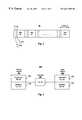
- FIG. 1is a representation of a frame structure in a WCDMA time slot in the system of FIG. 2 .
- FIG. 2is a layout of base station and a mobile station in a WCDMA system incorporating the principles of the present invention.
- FIG. 2Ais a block diagram of a base station transmitter in FIG. 2 .
- FIG. 2Bis a block diagram of a channel baseband model included in FIG. 2 .
- FIG. 2Cis a block diagram of mobile or base station receiver in FIG. 2 .
- FIG. 2Dis a block diagram of a mobile station transmitter in FIG. 2 .
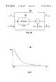
- FIG. 3is a graph of a channel power probability density function (pdf) and having a chi-square distributed random variable for two (2) degrees of freedom in the system of FIG. 2 .
- pdfchannel power probability density function
- FIG. 4is a graph of channel power probability density function versus power value at the beginning of each WCDMA time slot.
- FIG. 5is a graph of channel power pdf separated into three equal probable regions for the system of FIG. 2 .
- FIG. 6is a graph of pdf of the chi-square function for 2, 4, 6, and 8 degrees of freedom.
- FIG. 7is a model of the channel as a tapped delay line.
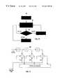
- FIG. 8is a flow chart of the base station transmitter in the system of FIG. 2 using Transmitter Power Control (TPC) bits in the WCDMA time slots for power management.
- TPCTransmitter Power Control
- FIG. 9is a flow chart of the base station transmitter in the system of FIG. 2 when operating the system with Seamless Rate Change (SRC).
- SRCSeamless Rate Change
- FIG. 10is a flow chart for selection of a spreading code in the system of FIG. 2 when a system modifies transmitter rate.
- FIG. 11illustrates an optimum demodulator for a CDMA system based on a rake receiver configuration of FIGS. 2-2D and 7 .
- FIG. 1illustrates a W-CDMA frame structure 10 including time slots 0 through 15 .
- Each frameincludes pilot bits 12 and transmitter power control bits 14 .
- pilot symbolsare time-multiplexed with data symbols and every slot starts with a group of pilot symbols ( 4 or 8 ) which maybe used to estimate or predict the channel and perform synchronization.
- the present inventionproposes a technique for adaptive modulation of a WCDMA system 100 shown in FIGS. 2-2D. It uses an algorithm for “Deterministic Channel Modeling and Long Range Prediction of Fast Mobile Radio Channels,” by T. Eyceoz, A. Duel-Hallen, and H. Hallen (Eyceoz), published in the IEEE Communication Letters, Vol. 2, No. 9, September 1998 for long range prediction of the mobile channels.
- a base station 101is linked to a mobile station 102 through a channel 103 , as further shown in FIGS. 2A-2D.
- a base station or forward system transmitter 104includes a terminal 105 for receiving a reverse transmitter signal. This is provided as an input to an orthogonal code generator 106 and an interleaver 107 for combining the reverse transmitter signal with a data source 108 after processing by a Viterbi encoder 110 .
- the processed signal as data symbolsis separated into first and second channels, real and imaginary, A and B, coupled to a Quadrature Phase Shift Keying (QPSK) unit 112 .
- QPSKQuadrature Phase Shift Keying
- a Multiplexer 116retrieves the channel A channel B outputs from the QPSK unit 112 and time multiplexes a pilot signal 114 with the data symbols in a series of data frames 10 (See FIG. 1 ), as will be explained in more detail hereinafter.
- the data framesare transmitted in channels A and B to a mobile receiver 150 (See FIG. 2C) using the OFDM Code generator 106 modified with a spreading or long code 118 , as will be described in more
- a baseband model 130is shown for channels A and B.
- Each channelis modeled as an Additive White Gaussian Noise (AWGN) 131 and a Time Bearing Flat Fading (TBFF) 132 in which the selected fading due to the multipath is negligible.
- AWGNAdditive White Gaussian Noise
- TBFFTime Bearing Flat Fading
- a mobile station or reverse system receiver 150is similar to the base or forward receiver 170 (See FIG. 2 ).
- Each receiverincludes matched filters 152 , 154 for antenna diversity in receiving channels A and B.
- the outputs of the match filtersare fed into a coherent rake receiver 156 and a channel prediction or estimation system 158 .
- the channel prediction systemdetermines the future attenuation of the channel for several milliseconds as described in the Eyceoz article, supra. The time interval is enough to allow both the base station and the mobile station to reconfigure their transmitters and receivers.
- An SRC/TPC logic device 160uses the prediction of the channel power and the channel coefficients to signal both the transmitter and receiver to reconfigure the channel power and/or channel rate according to whether the channel power is above or below a threshold level, as will be described in FIGS. 7 and 8, hereinafter.
- the SRC/TPC logic 160provides an input to the rake receiver 156 and to a de-interleaver 162 to adjust the transmission rate in both channels A and B during and after processing of the data in a QPSK device 164 .
- the SRC logiccan also determine which antenna is receiving the signal more accurately and signal its or remote transmitter to use that antenna for transmission to the base station which can reduce Multi Access Interference (MAI).
- the de-interleaver 162provides an output to a Viterbi decoder 166 , which provides an output signal 168 to a user.
- a dedicated pilot channel 114is used to signal the mobile station or the base station to reconfigure.
- a mobile station or reverse system transmitter 180includes a data source of symbols 182 encoded in a Viterbi encoder 184 and separated into channels A and B.
- the signalsare processed by an interleaver 186 and a rate one-half Viterbi encoder.
- the interleaved data bitsare mapped in a QPSK modulator 188 .
- the QPSK datais processed in a multiplexer 190 with the pilot signal 114 from the receiver 150 .
- An OFDM unit 192spreads the multiplexer output in channels A and B by an appropriate orthogonal code after which a long code 194 is added corresponding to the orthogonal code length negotiated at call establishment.
- An output of the channels A and Bis over sampled in pulse chap before being sent to the channel.
- a propagation channelIn wireless systems, a propagation channel is usually modeled as Raleigh distributed. Therefore the channel power has a chi-square probability distribution with 2 degrees of freedom.
- FIG. 3illustrates a power density function (pdf) 30 of a chi-square-distributed random variable for 2 degree of freedom, as more fully described in a book entitled “John Proakis, Digital Communications. New York: McGraw Hill, 1995.
- a 10 ms prediction time in one W-CDMA framea Base Station (BS) can predict the channel power profile of a Mobile Station (MS).
- the pdf of the predicted channel powershould theoretically be similar to the one in FIG. 3 .
- FIG. 5illustrates a three-region pdf of the channel power.
- P 2⁇ 0 A ⁇ P 2 ⁇ ⁇ ( ⁇ b ) ⁇ ⁇ p ⁇ ⁇ ( ⁇ b ) ⁇ ⁇ ⁇ ⁇ b + ⁇ A B ⁇ P 2 ⁇ ⁇ ( ⁇ b ) ⁇ ⁇ p ⁇ ⁇ ( ⁇ b ) ⁇ ⁇ ⁇ ⁇ b + ⁇ B ⁇ ⁇ P 2 ⁇ ⁇ ( ⁇ b ) ⁇ ⁇ p ⁇ ⁇ ( ⁇ b ) ⁇ ⁇ ⁇ ⁇ b
- the area under the exponential curve for each regionis equal to 0.333
- the probability that the system operates in poor, nominal and high channel conditionsare the same.
- the above equations for the channel powerbecomes as follows.
- a and Bare normalized for each region with their corresponding SNR value
- the channelis modeled as a tapped delay line D that is illustrated in FIG. 6 .
- the systemeither estimates or predicts channel coefficients at each rake finger F( 1 ) . . .
- Threshold valuesmay vary based on the number of rake finger used. In either case, the system performs long-range power prediction of each finger at the transmitter to compute the total channel power. Assuming a rake receiver has four (4) fingers with each multipath corresponding to one of the fingers, if the receiver chooses only two (2) of the highest power paths, which is using only two (2) fingers out of four (4), the total channel power considering the two (2) strongest paths is a chi-square function with four (4) degrees of freedom. Consequently, the threshold for adjustment of Adaptive Transmitter Power Control would be different from the previous case. Further details on a rake receiver and channel model are provided in the text “Digital Communications” by J. Proakis, published by McGraw Hill, New York, N.Y. (1995), pages 728-733 and fully incorporated herein by reference.
- a systemcan configure its transmitter at the beginning of each slot time.
- the MScan optimize its transmitter in order to minimize its probability of error at the Base Station (BS) receiver.
- Optimizationimproves the quality of the system by improved adaptive power control using the following techniques: (a) Transmitter Power Control (TPC) bits provided in the W-CDMA slots; Seamless Rate Change (SRC) using pilot bits, (c) Adaptive Transmitter Diversity (ATD) using pilot bits, and (d) adaptive power management based on a rake Receiver configuration, as follows:
- the MS transmittermodifies transmitter power rate by change a spreading factor (SF) or antenna based on a threshold set by the BS.
- SFspreading factor
- either the MS or BScompute “B & C” values (FIG. 5 .). These values are selected such that the system operates 33% of time in low-power region (0-A), 33% in the optimum power level (A-B) and 33% in the higher power region (B- ⁇ ). Since the total average power is 1, the long-term average power of the three-region system is also equal to 1.
- FIG. 7shows a flowchart 60 for the BS transmitter when operating the system in the TPC mode, as follows:
- the systemreceives one frame of seamless rate change commands (SRC) 62 .
- a test 64is performed in which the TPC bits are checked in each slot.
- the predicted power (P)is in the 0-A range
- the systemincrease the transmitter power by 3 dB by decreasing the rate in step 66 .
- the predicted power (P)goes above the B range
- the systemreduces the transmitter rate by 3 dB by increasing the rate in step 68 .
- the predicted poweris within the A and B ranges, the system makes no adjustment to the transmitter power.
- FIG. 8shows a flow chart 70 illustrating the operation of the system in the seamless rate change (SRC) mode.
- the systemreceives one frame of seamless rate change commands (SRC) 72 .
- a test 74is performed in which the SRS bits are checked in each slot
- the transmit rateis reduced in a step 76 and a longer spreading code (2*SF)is used.
- step 78when the predicted channel power goes above the “B” range, transmitter rate is increased and a shorter spreading code (1 ⁇ 2*SF) is used.
- the systemmakes no adjustment when the predicted channel power lies between “A & B.”
- an algorithm 80adjusts the spreading code C (1).
- the transmitted rateis reduced and a longer spreading code is used.
- the spreading codeis doubled when the threshold level is exceeded.
- the spreading codeis increased to 4 and 8 in blocks 86 and 88 .
- the transmitter rateis increased and a shorter spreading rate spreading code is used as shown in blocks 85 , 87 and 89 .
- the spreading codeis not adjusted when the predicted channel power lies at the threshold level.
- FIG. 10illustrates a flowchart 90 for the BS transmitter when operating the system with Adaptive Transmitter Diversity.
- the BS receiverpredicts the channel power for the two input receivers after receiving a frame of Power (P) commands in step 92 .
- the BStransmit the predicted channel power values of one frame to the MS receiver via the pilot bits.
- the MScompares the Power values to the threshold in a step 94 and selects the transmit antenna # 1 or # 2 that propagates through the better of the two transmit paths. This process can be reversed and the role of BS and MS can be altered such that the BS perform the antenna selection and the MS performs the prediction.
- FIG. 11illustrates an optimum demodulator for CDMA system based on a Rake receiver 156 (See FIG. 2 c ) configuration.
- the rake receiver 156may use all or some of the fingers output to sum and integrate. Based on a decision made at the receiver, the system can determine the number of the fingers that are going to be used at the receiver and report to the transmitter for the optimum power and rate management. As explained previously, the threshold values may vary based on the number of rake finger used. The finger information may be transmitted to the transmitter from the receiver for computation of the optimum threshold value.
- a WCDMA systemhas been disclosed with adaptive channel power control using Transmitter Power Control Bits (TPCB) in the frame transmit slots and seamless rate change and/or adaptive transmitter diversity using pilot bits.
- the WCDMA systemis capable of supporting variable data rate by configuring its receiver and transmitter to the data rate determined at a call establishment or adaptively change during transmission. It can be accomplished by means of estimating or predicting the channel coefficients at each rake finger and performing maximal ratio combining by multiplying each finger with its conjugate or chooses the ones with the highest energy and performing maximal ratio combining on the selected fingers. In either case system performs the long-range power prediction of each finger at the transmitter to compute the total channel power. Pilot set channels associated with individual data channels carry control signals to adjust transmit and receive power levels accordingly. As a result, throughput is maximized, channel capacity increased while reducing transmit power and overall maintaining connectivity.
- TPCBTransmitter Power Control Bits
Landscapes
- Engineering & Computer Science (AREA)
- Computer Networks & Wireless Communication (AREA)
- Signal Processing (AREA)
- Mobile Radio Communication Systems (AREA)
Abstract
Description
This invention claims the benefit of the filing date of Provisional Application, Serial No. 60/148,938 filed Aug. 13, 1999, entitled “Adaptive Transmitter Power Control Based Of Rake Receiver Configuration”, assigned to the assignee of the present invention and fully incorporated herein by reference.
This invention is related to copending application, Ser. No. 09/413,991, filed Oct. 7, 1999 entitled “Adaptive Power Control In Wideband CDMA Cellular Systems (WCDMA) And Methods Of Operation”, assigned to the same assignee as that of the present invention and fully incorporated herein by reference.
(1) Field of Invention
This invention relates to communication systems and methods of operation. More particularly, the invention relates to adaptive power management based on a Rake Receiver configuration in WCDMA systems and methods of operation.
(2) Description of the Prior Art
In wireless communication system, signal fading due to multipath radio propagation severely degrades the performance and imposes high transmitter power requirement. Since the characteristic of a channel changes rapidly, a transmitter and a receiver can not be configured to operate at their optimum performance level and therefore, they fail to exploit full potential of the wireless system. Code-Division Multiple Access (CDMA) provides increased capacity due to the fact that each user in this system occupies the entire frequency band and therefore there is no waste of bandwidth due to channel spacing. Several systems have been proposed for the third generation wireless system. The most popular system under study is the Wideband CDMA (W-CDMA) system, described in an article entitled “Channel Estimation for the W-CDMA System, Performance and Robustness Analyses from a Terminal Perspective,” by B. Lindof, C. Ostberg, and H. Eriksson, published at the IEEE Vehicular Technology Conference.Document 90. May 1999.
Developers of the third generation wireless system in the industry envision crystal clear voice service, video conferencing from anywhere, high speed mobile Web surfing, and thousands of advanced applications right over the wireless phone or handheld PC. Generally, any enhancement to the system that can improve delivery of high-speed data, voice and video over mobile devices along with increasing the battery life are challenging topics for consideration and improvement.
In papers entitled “Symbol Rate and Modulation Level-Controlled Adaptive Modulation/TDMA/TDD System for High-Bit-Rate Wireless Data Transmission,” by T.Ue, S. Sampei, N. Morinaga, and K. Hamaguchi, published in the IEEE Transaction on Vehicular Technology, Vol. 47. No. 4, Pp. 1134-1147, November 1998, pages 1134-1147, and “Adaptive Coding and Processing Gain Control with Channel Activation for Multimedia DS/CDMA System,” by S. Abeta, S. Sampei, and N. Morinaga, published in IEICE Transaction on Communication, Vol. E80-B, No. 4. April 1997, pages the authors propose a symbol rate, gain and coding change scheme through the use of feedback transmission of the information from the Base Station (BS) to the Mobile Station (MS). In these proposals the quality of the channel was determined on the basis of the calculation of the short-term signal to interference ratio C/(N0+I0) at the BS receiver, where C is Signal Power; N0is AWGN Power, and I0is Interference from other users. However, in a wideband environment, due to the presence of Inter-Symbol Interference (ISI), the short term Signal To Noise Ratio (SNR) is inadequate for measuring the quality of the channel, as described in an article entitled “Upper-bound Performance of a Wideband Burst-by-Burst Adaptive Modem,” by C. H. Wong, and L. Hanzo, published in the IEEE Vehicular Technology Conference. Document 483. May 1999, pages.
In these adaptive schemes, thresholds are set based on the probability distribution function (pdf) of the channel power. In a 1-user model with one channel path, the pdf of the channel power would be an exponential or chi-square function with 2 degrees of freedom. However, in a CDMA receiver, normally the rake receiver has several fingers. That is at the receiver, the system either estimates or predicts the channel coefficients at each rake finger and performs maximal ratio combining by multiplying each finger with its conjugate or chooses the ones with the highest energy and performs maximal ratio combining on the selected fingers. In either case system performs the long-range power prediction of each finger at the transmitter to compute the total channel power.
Other prior art related to WCDMA systems with improved performance include:
U.S. Pat. No. 5,822,381 to E. Tiedemann, Jr. et al., issued Oct. 13, 1998 (Tiedemann) discloses a method and apparatus for controlling transmission power in a variable rate communication system. The method disclosed provides for a closed loop power control method. A first remote station controls the transmission power of a second remote station by transmitting a rate dependent power control signal to the second remote communications system. Since only the second communications system knows its transmission rate a priori, it must determine a course of action in accordance with both the received power control signal and the knowledge of its transmission rate.
U.S. Pat. No. 5,715,526 to L. A. Weaver, Jr., et al., issued Feb. 3, 1998, (Weaver) discloses an apparatus and method for controlling a final transmit power, Y of a base station in a cellular communications system that has several channels. The base station has a transmit power tracking gain, Y′ and a radio frequency transmit power, W. The apparatus comprises channel elements for calculating expected power Pk,a−Pkf, each of which corresponds to a channel. The apparatus also comprises a transceiver system controller (BTSC) for generating a desired output power, Ydof the base station, including an adder for summing the expected powers. The apparatus also includes a transmit power detector for measuring ‘Y’ to obtain the measured transmit power. The apparatus further comprises a radio frequency interface card (RFIC) for generating ‘Y’. Finally, the apparatus includes a gain unit for processing ‘Y’ and W to obtain the final transmitted power, Y.
U.S. Pat. No. 5,383,219 to C. E. Wheatley, III, et al., (Wheatley) issued Jan. 17, 1995, discloses a power control process which enables a mobile radio telephone to continuously update the base station on the power output required. The base station sends a frame to the mobile at a particular rate. If the mobile received and decoded the frame correctly, the mobile sets a power control bit and the next frame to be transmitted to the base station. Based on the error rate of the received power control bits, the base station determines whether to increase or decrease the transmit power.
U.S. Pat. No. 5,729,557 to S. H. Gardner, et al, issued Mar. 17, 1998, (Gardner) discloses a method and apparatus for using multiple code rates for forward error correction in a cellular digital radio communication system. Each base station broadcasts a quantity called the power product (PP) which is equal to the base transmit power, PBTmultiplied by the power level received at the base station, PBR. For a mobile-unit to determine it's appropriate transmit power, PMTrequires measuring the power received, PMRat the mobile unit and performing a calculation. When the channel path loss is large it is possible that the power control calculation will return a value greater than the maximum transmit power capability of the mobile unit. In such case, the mobile unit selects a lower code rate. The base station receiver sensitivity improves as the code rate decreases, so the result is similar to increasing the transmit power. In the preferred embodiment, the invention uses three different code rates. In most cases, the code rate used is two-thirds, but when a mobile unit determines that it needs more transmit power than it is capable of providing, the code range is changed to one-half, and in severe cases the code rate is changed to one-third.
JP6-276176 to Tetsuyoshi et al, published Sep. 30, 1994 (Tetsuyoshi) discloses reducing intra-signal interference at the time of demodulating signals from respective remote stations by preparing plural chip rates and appropriately allocating them for the respective remote stations. When the power level of reception signals initially detected by reception power detection or the signals from remote stations, a chip rate deciding circuit judges that the reception power level causes strong interference and the inverse spread demodulation of the signals. The present chip rate in this case is changed and the remote station is informed from a chip rate informing circuit. In a remote station a spreading code is generated corresponding to the chip rate informed from the base station. A spreading code is generated supplied to a spectrum spread modulation part to perform spread spectrum spread modulation and transmitted to the base station. Thus, the base station performs an inverse spread processing by the chip rate and interference is reduced at the remote stations.
In prior art systems, past estimates of the signal to interference ratio are used to adjust the transmitter power. Due to the fading of the wireless channels, past estimates of the received SNR is not an adequate technique for optimum power control. None of the prior art uses future prediction of the channel power by calculating a long-range prediction of each finger of a rake receiver and based on the estimated total channel power distribution function to set the optimum threshold to control transmitter gain and rate as in the present invention.
An object of the invention is a communication system such as a WCDMA system and method of operation having adaptive modulation for improved system throughput, channel capacity and transmit power control.
Another object is a WCDMA system and method of operation with improved adaptive power management using power levels of a Rake Receiver configuration.
Another object is a WCDMA system and method of operation which predicts power levels of each finger in a Rake receiver and the strongest power levels being used in determining the optimum transmitter power or rate control for operating the system transmitters and receivers.
These and other objects, features and advantages are achieved in a WCDMA system and method which maximizes throughput, control channel capacity/transmit power and maintains connectivity between a base and a mobile station using the predicted power levels of each finger in a rake receiver with the strongest ones used in determining the optimum transmitter power or rate control for operating the system tranmitters and receivers. The WCDMA system includes a Base Station (BS) or forward transmitter and a pilot channel that transmits control signals between a Mobile Station (MS) and BS to reconfigure their transmitter/receiver according to the prediction of the channel power and channel power probability density function separated into three distinct equal probable regions. Data signals are encoded using a one-half Viterbi encoder and interleaved. The interleaved data bits are modulated using Quadrature Phase Shift Keying (QPSK) modulation. The QPSK data is multiplexed with the pilot channel and spread by an appropriate code in an OFDM transmitter modified by a long code. Output of the transmitter may be provided to two diverse antennas for reliable communications to the receiver. Data may be received at two diverse antennas. The outputs are provided to match filters coupled to a coherent rake receiver and a channel prediction system. The future attenuation of the channel coefficients and power are determined by the prediction system for several milliseconds. The power levels of each finger in the Rake receiver can be predicted and the strongest ones used in determining the optimum transmitter power or rate control for operating the system transmitters and receivers based on computing a long range power prediction of each finger of the rake receiver.
The invention will be further understood from the following detailed description of a preferred embodiment taken in conjunction with an appended drawing, in which:
FIG. 1 is a representation of a frame structure in a WCDMA time slot in the system of FIG.2.
FIG. 2 is a layout of base station and a mobile station in a WCDMA system incorporating the principles of the present invention.
FIG. 2A is a block diagram of a base station transmitter in FIG.2.
FIG. 2B is a block diagram of a channel baseband model included in FIG.2.
FIG. 2C is a block diagram of mobile or base station receiver in FIG.2.
FIG. 2D is a block diagram of a mobile station transmitter in FIG.2.
FIG. 3 is a graph of a channel power probability density function (pdf) and having a chi-square distributed random variable for two (2) degrees of freedom in the system of FIG.2.
FIG. 4 is a graph of channel power probability density function versus power value at the beginning of each WCDMA time slot.
FIG. 5 is a graph of channel power pdf separated into three equal probable regions for the system of FIG.2.
FIG. 6 is a graph of pdf of the chi-square function for 2, 4, 6, and 8 degrees of freedom.
FIG. 7 is a model of the channel as a tapped delay line.
FIG. 8 is a flow chart of the base station transmitter in the system of FIG. 2 using Transmitter Power Control (TPC) bits in the WCDMA time slots for power management.
FIG. 9 is a flow chart of the base station transmitter in the system of FIG. 2 when operating the system with Seamless Rate Change (SRC).
FIG. 10 is a flow chart for selection of a spreading code in the system of FIG. 2 when a system modifies transmitter rate.
FIG. 11 illustrates an optimum demodulator for a CDMA system based on a rake receiver configuration of FIGS. 2-2D and7.
In WCDMA systems, symbols are transmitted using Quadrature Phase Shift Keying (QPSK) and Direct Sequence CDMA (DS-CDMA). The chip rate is 4.096 MHz. Each physical channel is organized in a frame structure, such that each slot consists of 2560 chips. This is described in an article entitled “Channel Estimation for the W-CDMA System, Performance and Robustness Analyses from a Terminal Perspective,” by B. Lindof, C. Ostberg, and H. Eriksson, published in the IEEE Vehicular Technology Conference.Document 90. May 1999. FIG. 1 illustrates a W-CDMA frame structure 10 includingtime slots 0 through15. Each frame includespilot bits 12 and transmitterpower control bits 14. For the down link, pilot symbols are time-multiplexed with data symbols and every slot starts with a group of pilot symbols (4 or8) which maybe used to estimate or predict the channel and perform synchronization.
The present invention proposes a technique for adaptive modulation of aWCDMA system 100 shown in FIGS. 2-2D. It uses an algorithm for “Deterministic Channel Modeling and Long Range Prediction of Fast Mobile Radio Channels,” by T. Eyceoz, A. Duel-Hallen, and H. Hallen (Eyceoz), published in the IEEE Communication Letters, Vol. 2, No. 9, September 1998 for long range prediction of the mobile channels.
In FIG. 2, a base station101 is linked to amobile station 102 through achannel 103, as further shown in FIGS. 2A-2D.
In FIG. 2A, a base station orforward system transmitter 104 includes a terminal105 for receiving a reverse transmitter signal. This is provided as an input to anorthogonal code generator 106 and aninterleaver 107 for combining the reverse transmitter signal with adata source 108 after processing by aViterbi encoder 110. The processed signal as data symbols is separated into first and second channels, real and imaginary, A and B, coupled to a Quadrature Phase Shift Keying (QPSK)unit 112. AMultiplexer 116 retrieves the channel A channel B outputs from theQPSK unit 112 and time multiplexes apilot signal 114 with the data symbols in a series of data frames10 (See FIG.1), as will be explained in more detail hereinafter. The data frames are transmitted in channels A and B to a mobile receiver150 (See FIG. 2C) using theOFDM Code generator 106 modified with a spreading orlong code 118, as will be described in more detail hereinafter.
In FIG. 2B, abaseband model 130 is shown for channels A and B. Each channel is modeled as an Additive White Gaussian Noise (AWGN)131 and a Time Bearing Flat Fading (TBFF)132 in which the selected fading due to the multipath is negligible.
In FIG. 2C, a mobile station orreverse system receiver 150 is similar to the base or forward receiver170 (See FIG.2). Each receiver includes matchedfilters coherent rake receiver 156 and a channel prediction orestimation system 158. The channel prediction system determines the future attenuation of the channel for several milliseconds as described in the Eyceoz article, supra. The time interval is enough to allow both the base station and the mobile station to reconfigure their transmitters and receivers. An SRC/TPC logic device 160 uses the prediction of the channel power and the channel coefficients to signal both the transmitter and receiver to reconfigure the channel power and/or channel rate according to whether the channel power is above or below a threshold level, as will be described in FIGS. 7 and 8, hereinafter. The SRC/TPC logic 160 provides an input to therake receiver 156 and to a de-interleaver162 to adjust the transmission rate in both channels A and B during and after processing of the data in aQPSK device 164. The SRC logic can also determine which antenna is receiving the signal more accurately and signal its or remote transmitter to use that antenna for transmission to the base station which can reduce Multi Access Interference (MAI). The de-interleaver162 provides an output to aViterbi decoder 166, which provides anoutput signal 168 to a user. Adedicated pilot channel 114 is used to signal the mobile station or the base station to reconfigure.
In FIG. 2D, a mobile station orreverse system transmitter 180 includes a data source ofsymbols 182 encoded in aViterbi encoder 184 and separated into channels A and B. The signals are processed by aninterleaver 186 and a rate one-half Viterbi encoder. The interleaved data bits are mapped in aQPSK modulator 188. The QPSK data is processed in amultiplexer 190 with thepilot signal 114 from thereceiver 150. (See FIG. 2C.) AnOFDM unit 192 spreads the multiplexer output in channels A and B by an appropriate orthogonal code after which along code 194 is added corresponding to the orthogonal code length negotiated at call establishment. An output of the channels A and B is over sampled in pulse chap before being sent to the channel.
In wireless systems, a propagation channel is usually modeled as Raleigh distributed. Therefore the channel power has a chi-square probability distribution with 2 degrees of freedom. The following equations illustrate this relation:

Where:
P(Y)isChannel Powerpdfy=α2;
σ2=variance.
In general, the Chi-square function of m degrees of freedom that is described in a book entitles “C. W. Helstrom, Statistical Theory of Signal Detection, rev. 2ndEd. New York: Pergamon, 1968,” Is the sum of the squares of m normally distributed random deviates, each having unit variance.

In general the pdf of the γbfor multi-paths fading channel where the channel power has Chi-square characteristic function with 2L degree of freedom is given by

FIG. 3 illustrates a power density function (pdf)30 of a chi-square-distributed random variable for 2 degree of freedom, as more fully described in a book entitled “John Proakis, Digital Communications. New York: McGraw Hill, 1995. Applying a long-range channel prediction process, a 10 ms prediction time in one W-CDMA frame, a Base Station (BS) can predict the channel power profile of a Mobile Station (MS). The pdf of the predicted channel power should theoretically be similar to the one in FIG.3.
An experiment was conducted to prove the performance of the process. In this experiment, a BS prediction of the channel power was assumed at the beginning of each slot for the duration of a frame is perfect. The pdf of 4 Independent Identical Distributed (IID) channel powers40 was computed and is illustrated in FIG.4.
By definition to obtain the probability of error for a BPSK (2 BPSK same as QPSK) system is evaluated by the integral,


The general Closed-form solution of the error probability for the multipath fading channel model can be expressed as:

In the present invention, the pdf of the channel power is divided into several regions in which the probability of every region is equal. FIG. 5 illustrates a three-region pdf of the channel power.

In the case where the pdf is divided into three equal probable regions (0-A; A-B; B-∞), the area under the exponential curve for each region is equal to 0.333 In other words, the probability that the system operates in poor, nominal and high channel conditions are the same. In the three-region system of FIG. 5, the above equations for the channel power becomes as follows. In the following equation, A and B are normalized for each region with their corresponding SNR value In a multipath enviroment, the channel is modeled as a tapped delay line D that is illustrated in FIG.6. In one embodiment, the system either estimates or predicts channel coefficients at each rake finger F(1) . . . F(N) and performs maximal ratio combining by multiplying each finger F with its conjugate C or chooses the fingers with the highest energy and performs maximal ratio combining on the selected fingers. Threshold values may vary based on the number of rake finger used. In either case, the system performs long-range power prediction of each finger at the transmitter to compute the total channel power. Assuming a rake receiver has four (4) fingers with each multipath corresponding to one of the fingers, if the receiver chooses only two (2) of the highest power paths, which is using only two (2) fingers out of four (4), the total channel power considering the two (2) strongest paths is a chi-square function with four (4) degrees of freedom. Consequently, the threshold for adjustment of Adaptive Transmitter Power Control would be different from the previous case. Further details on a rake receiver and channel model are provided in the text “Digital Communications” by J. Proakis, published by McGraw Hill, New York, N.Y. (1995), pages 728-733 and fully incorporated herein by reference.
Since the predicted power level of every transmit slots is available at a Mobile Station (MS), a system can configure its transmitter at the beginning of each slot time. In this case the MS can optimize its transmitter in order to minimize its probability of error at the Base Station (BS) receiver. Optimization improves the quality of the system by improved adaptive power control using the following techniques: (a) Transmitter Power Control (TPC) bits provided in the W-CDMA slots; Seamless Rate Change (SRC) using pilot bits, (c) Adaptive Transmitter Diversity (ATD) using pilot bits, and (d) adaptive power management based on a rake Receiver configuration, as follows:
A. General Procedure
The MS transmitter modifies transmitter power rate by change a spreading factor (SF) or antenna based on a threshold set by the BS. In such case, either the MS or BS compute “B & C” values (FIG.5.). These values are selected such that the system operates 33% of time in low-power region (0-A), 33% in the optimum power level (A-B) and 33% in the higher power region (B-∞). Since the total average power is 1, the long-term average power of the three-region system is also equal to 1.
B. TPC
When the system operates in a TPC mode, and when the predicted channel power falls below the “A-0” range, the system increases the transmitter power by 3 dB. When the predicted channel power goes above the “B” range, the system reduces its transmitter power by 3 dB. And finally the system makes no adjustment when the predicted channel power lies between “A & B.” FIG. 7 shows aflowchart 60 for the BS transmitter when operating the system in the TPC mode, as follows:
At start, the system receives one frame of seamless rate change commands (SRC)62. Atest 64 is performed in which the TPC bits are checked in each slot. When the predicted power (P) is in the 0-A range, the system increase the transmitter power by 3 dB by decreasing the rate instep 66. When the predicted power (P) goes above the B range, the system reduces the transmitter rate by 3 dB by increasing the rate instep 68. When the predicted power is within the A and B ranges, the system makes no adjustment to the transmitter power.
C. SRC
FIG. 8 shows aflow chart 70 illustrating the operation of the system in the seamless rate change (SRC) mode. At start, the system receives one frame of seamless rate change commands (SRC)72. Atest 74 is performed in which the SRS bits are checked in each slot When the predicted channel power falls below “A” range, the transmit rate is reduced in astep 76 and a longer spreading code (2*SF)is used. Instep 78, when the predicted channel power goes above the “B” range, transmitter rate is increased and a shorter spreading code (½*SF) is used. And finally the system makes no adjustment when the predicted channel power lies between “A & B.”
In FIG. 9, analgorithm 80 adjusts the spreading code C (1). When the predicted channel power falls below a threshold, the transmitted rate is reduced and a longer spreading code is used. In block84 the spreading code is doubled when the threshold level is exceeded. The spreading code is increased to4 and8 in blocks86 and88. When the predicted channel power goes above the threshold, the transmitter rate is increased and a shorter spreading rate spreading code is used as shown in blocks85,87 and89. The spreading code is not adjusted when the predicted channel power lies at the threshold level.
D. ATD
FIG. 10 illustrates aflowchart 90 for the BS transmitter when operating the system with Adaptive Transmitter Diversity. When the System operates in ATD mode, the BS receiver predicts the channel power for the two input receivers after receiving a frame of Power (P) commands instep 92. The BS transmit the predicted channel power values of one frame to the MS receiver via the pilot bits. Similar to the TPC or SRC processes60,70, the MS compares the Power values to the threshold in astep 94 and selects the transmitantenna # 1 or #2 that propagates through the better of the two transmit paths. This process can be reversed and the role of BS and MS can be altered such that the BS perform the antenna selection and the MS performs the prediction.
E) Rake Receiver Configuration:
FIG. 11 illustrates an optimum demodulator for CDMA system based on a Rake receiver156 (See FIG. 2c) configuration. As illustrated, therake receiver 156 may use all or some of the fingers output to sum and integrate. Based on a decision made at the receiver, the system can determine the number of the fingers that are going to be used at the receiver and report to the transmitter for the optimum power and rate management. As explained previously, the threshold values may vary based on the number of rake finger used. The finger information may be transmitted to the transmitter from the receiver for computation of the optimum threshold value.
Summarizing, a WCDMA system has been disclosed with adaptive channel power control using Transmitter Power Control Bits (TPCB) in the frame transmit slots and seamless rate change and/or adaptive transmitter diversity using pilot bits. The WCDMA system is capable of supporting variable data rate by configuring its receiver and transmitter to the data rate determined at a call establishment or adaptively change during transmission. It can be accomplished by means of estimating or predicting the channel coefficients at each rake finger and performing maximal ratio combining by multiplying each finger with its conjugate or chooses the ones with the highest energy and performing maximal ratio combining on the selected fingers. In either case system performs the long-range power prediction of each finger at the transmitter to compute the total channel power. Pilot set channels associated with individual data channels carry control signals to adjust transmit and receive power levels accordingly. As a result, throughput is maximized, channel capacity increased while reducing transmit power and overall maintaining connectivity.
While the invention has been shown and described in a preferred embodiment, various changes can be made without departing from the spirit and scope of the invention as defined in the appended claims, in which:
Claims (12)
1. A Wide-band Code Division Multiple Access (“WCDMA”) system comprising a base station and a mobile station;
a channel including a baseband signal having a variable transmission rate and including a pilot channel coupling the base station and the mobile station;
means responsive to the baseband signal for predicting future power attenuation on the channels based on computing a long range power prediction of each finger of a rake receiver; and
means responsive to the channel prediction means to signal both the transmitter and receiver over the pilot channel to reconfigure the transmission rate according to the predicted power attenuation.
2. The system ofclaim 1 further comprising means establishing a power threshold in the channel.
3. The system ofclaim 2 further comprising means for increasing the transmission rate when the predicted channel power goes above the threshold.
4. The system ofclaim 2 further comprising means for decreasing the transmission rate when the predicted channel power falls below the threshold.
5. The system ofclaim 1 further comprising:
means for estimating or predicting channel coefficients at each rake finger F(1) . . . F(N); and means for performing maximal power ratio combining by multiplying each finger F with its conjugate C.
6. The system ofclaim 1 further comprising:
means for choosing the fingers with the highest energy and performing maximal ratio combining on the selected fingers.
7. In a wide band code division multiple access (“WBCDMA”) system comprising a base station transmitter and receiver, a mobile station transmitter and receiver, dual channel each including a baseband signal having a variable transmission rate and a pilot channel coupling the base station and the mobile station, a method for improved throughput, channel capacity and transmit power control of the system, comprising the steps of:
predicting future power attenuation on the channels based on computing a long range power prediction of each finger of a rake receiver; and
signaling both the transmitter and receiver over the pilot channel to reconfigure the transmission rate according to the predicted power attenuation.
8. The method ofclaim 7 further comprising the step of:
establishing a power threshold in the channels.
9. The method ofclaim 7 further comprising the step of:
estimating or predicting channel coefficients at each rake finger F(1) . . . F(N); and performing maximal power ratio combining by multiplying each finger F with its conjugate C.
10. The method ofclaim 7 further comprising the step of:
choosing the fingers with the highest energy and performing maximal ratio combining on the selected fingers.
11. The method ofclaim 8 further comprising the step of:
increasing the transmission rate when the predicted channel power goes above the threshold.
12. The method ofclaim 11 further comprising the step of:
decreasing the transmission rate when the predicted channel power falls below the threshold.
Priority Applications (1)
| Application Number | Priority Date | Filing Date | Title |
|---|---|---|---|
| US09/413,935US6621808B1 (en) | 1999-08-13 | 1999-10-07 | Adaptive power control based on a rake receiver configuration in wideband CDMA cellular systems (WCDMA) and methods of operation |
Applications Claiming Priority (2)
| Application Number | Priority Date | Filing Date | Title |
|---|---|---|---|
| US14893899P | 1999-08-13 | 1999-08-13 | |
| US09/413,935US6621808B1 (en) | 1999-08-13 | 1999-10-07 | Adaptive power control based on a rake receiver configuration in wideband CDMA cellular systems (WCDMA) and methods of operation |
Publications (1)
| Publication Number | Publication Date |
|---|---|
| US6621808B1true US6621808B1 (en) | 2003-09-16 |
Family
ID=27807369
Family Applications (1)
| Application Number | Title | Priority Date | Filing Date |
|---|---|---|---|
| US09/413,935Expired - LifetimeUS6621808B1 (en) | 1999-08-13 | 1999-10-07 | Adaptive power control based on a rake receiver configuration in wideband CDMA cellular systems (WCDMA) and methods of operation |
Country Status (1)
| Country | Link |
|---|---|
| US (1) | US6621808B1 (en) |
Cited By (121)
| Publication number | Priority date | Publication date | Assignee | Title |
|---|---|---|---|---|
| US20010021182A1 (en)* | 2000-02-29 | 2001-09-13 | Kabushiki Kaisha Toshiba | Transmitter apparatus and receiver apparatus and base station making use of orthogonal frequency division multiplexing and spectrum spreading |
| US20020080742A1 (en)* | 1997-12-17 | 2002-06-27 | Tantivy Communications, Inc. | System and method for maintaining timing of synchronization messages over a reverse link of a CDMA wireless communication system |
| US20020101909A1 (en)* | 2001-01-29 | 2002-08-01 | Tao Chen | Method and apparatus for managing finger resources in a communication system |
| US20020160721A1 (en)* | 2000-03-30 | 2002-10-31 | Hideki Kanemoto | Radio communication apparatus and radio communication method |
| US20030048753A1 (en)* | 2001-08-30 | 2003-03-13 | Ahmad Jalali | Method and apparatus for multi-path elimination in a wireless communication system |
| US20030109225A1 (en)* | 2001-09-27 | 2003-06-12 | Aldajani Mansour A. | Closed loop power control techniques |
| US20030128674A1 (en)* | 1998-03-02 | 2003-07-10 | Samsung Electronics Co., Ltd. | Rate control device and method for CDMA communication system |
| US20040131022A1 (en)* | 2001-09-28 | 2004-07-08 | Fujitsu Limited | Channel prediction device and method thereof |
| US20040166886A1 (en)* | 2003-02-24 | 2004-08-26 | Rajiv Laroia | Pilot signals for use in multi-sector cells |
| US20040229640A1 (en)* | 2002-01-02 | 2004-11-18 | Nokia Corporation | Control based on adaptive spreading factor |
| WO2004077685A3 (en)* | 2003-02-24 | 2004-12-16 | Flarion Technologies Inc | Pilot signals for use in multi-sector cells |
| US20050009578A1 (en)* | 2003-07-07 | 2005-01-13 | Yonghe Liu | Optimal power saving scheduler for 802.11e APSD |
| US6888817B1 (en)* | 2000-02-01 | 2005-05-03 | Industrial Technology Research Institute | Method and apparatus for positioning a mobile station in a TDMA system |
| US6996195B2 (en)* | 1999-12-22 | 2006-02-07 | Nokia Mobile Phones Ltd. | Channel estimation in a communication system |
| US20060030366A1 (en)* | 2001-08-17 | 2006-02-09 | Electronics And Telecommunications Research Institute | Apparatus for forward beamforming using feedback of multipath information and method thereof |
| US20060083161A1 (en)* | 2003-02-24 | 2006-04-20 | Rajiv Laroia | Methods and apparatus for determining, communicating and using information which can be used for interference control purposes |
| US20060105719A1 (en)* | 2000-11-16 | 2006-05-18 | Katsutoshi Itoh | Information processing apparatus and communication apparatus |
| US20060223461A1 (en)* | 2005-03-08 | 2006-10-05 | Rajiv Laroia | Digital broadcast methods and apparatus |
| US7236747B1 (en)* | 2003-06-18 | 2007-06-26 | Samsung Electronics Co., Ltd. (SAIT) | Increasing OFDM transmit power via reduction in pilot tone |
| US7307977B1 (en)* | 2002-10-01 | 2007-12-11 | Comsys Communication & Signal Processing Ltd. | Information transfer and interrupt event scheduling scheme for a communications transceiver incorporating multiple processing elements |
| US20080102872A1 (en)* | 2004-04-09 | 2008-05-01 | Sheng Liu | Downlink Power Control Method and Apparatus in the Distributed Antenna System |
| US7400692B2 (en) | 2004-01-14 | 2008-07-15 | Interdigital Technology Corporation | Telescoping window based equalization |
| US20080194280A1 (en)* | 2005-04-22 | 2008-08-14 | Telefonaktiebolaget Lm Ericcson | Method And Apparatus Relating To Power Control |
| US20080214222A1 (en)* | 2003-02-06 | 2008-09-04 | Ntt Docomo, Inc. | Mobile station capable of and a method for generating chip patterns for transmission |
| US20080225914A1 (en)* | 2007-03-16 | 2008-09-18 | Aravanan Gurusami | System of method for dynamic range extension |
| US7437135B2 (en) | 2003-10-30 | 2008-10-14 | Interdigital Technology Corporation | Joint channel equalizer interference canceller advanced receiver |
| US7746830B2 (en) | 1998-06-01 | 2010-06-29 | Interdigital Technology Corporation | System and method for maintaining wireless channels over a reverse link of a CDMA wireless communication system |
| US7773566B2 (en) | 1998-06-01 | 2010-08-10 | Tantivy Communications, Inc. | System and method for maintaining timing of synchronization messages over a reverse link of a CDMA wireless communication system |
| US20110217938A1 (en)* | 2010-03-05 | 2011-09-08 | Ching-Hwa Yu | Wireless Transceiver Device and Control Method |
| US8134980B2 (en) | 1998-06-01 | 2012-03-13 | Ipr Licensing, Inc. | Transmittal of heartbeat signal at a lower level than heartbeat request |
| US8155096B1 (en)* | 2000-12-01 | 2012-04-10 | Ipr Licensing Inc. | Antenna control system and method |
| US8175120B2 (en) | 2000-02-07 | 2012-05-08 | Ipr Licensing, Inc. | Minimal maintenance link to support synchronization |
| US8274954B2 (en) | 2001-02-01 | 2012-09-25 | Ipr Licensing, Inc. | Alternate channel for carrying selected message types |
| US8437251B2 (en) | 2005-12-22 | 2013-05-07 | Qualcomm Incorporated | Methods and apparatus for communicating transmission backlog information |
| US8493141B2 (en) | 2010-04-19 | 2013-07-23 | Rf Micro Devices, Inc. | Pseudo-envelope following power management system |
| US8503938B2 (en) | 2004-10-14 | 2013-08-06 | Qualcomm Incorporated | Methods and apparatus for determining, communicating and using information including loading factors which can be used for interference control purposes |
| US8514771B2 (en) | 2005-12-22 | 2013-08-20 | Qualcomm Incorporated | Methods and apparatus for communicating and/or using transmission power information |
| US8519788B2 (en) | 2010-04-19 | 2013-08-27 | Rf Micro Devices, Inc. | Boost charge-pump with fractional ratio and offset loop for supply modulation |
| US8571498B2 (en) | 2010-08-25 | 2013-10-29 | Rf Micro Devices, Inc. | Multi-mode/multi-band power management system |
| US8588713B2 (en) | 2011-01-10 | 2013-11-19 | Rf Micro Devices, Inc. | Power management system for multi-carriers transmitter |
| US8611402B2 (en) | 2011-02-02 | 2013-12-17 | Rf Micro Devices, Inc. | Fast envelope system calibration |
| US8618868B2 (en) | 2011-08-17 | 2013-12-31 | Rf Micro Devices, Inc. | Single charge-pump buck-boost for providing independent voltages |
| US8624760B2 (en) | 2011-02-07 | 2014-01-07 | Rf Micro Devices, Inc. | Apparatuses and methods for rate conversion and fractional delay calculation using a coefficient look up table |
| US8626091B2 (en) | 2011-07-15 | 2014-01-07 | Rf Micro Devices, Inc. | Envelope tracking with variable compression |
| US8633766B2 (en) | 2010-04-19 | 2014-01-21 | Rf Micro Devices, Inc. | Pseudo-envelope follower power management system with high frequency ripple current compensation |
| US8638877B2 (en) | 2001-02-01 | 2014-01-28 | Intel Corporation | Methods, apparatuses and systems for selective transmission of traffic data using orthogonal sequences |
| US8694042B2 (en) | 2005-10-14 | 2014-04-08 | Qualcomm Incorporated | Method and apparatus for determining a base station's transmission power budget |
| US8760228B2 (en) | 2011-06-24 | 2014-06-24 | Rf Micro Devices, Inc. | Differential power management and power amplifier architecture |
| US8782107B2 (en) | 2010-11-16 | 2014-07-15 | Rf Micro Devices, Inc. | Digital fast CORDIC for envelope tracking generation |
| US8792840B2 (en) | 2011-07-15 | 2014-07-29 | Rf Micro Devices, Inc. | Modified switching ripple for envelope tracking system |
| US8811348B2 (en) | 2003-02-24 | 2014-08-19 | Qualcomm Incorporated | Methods and apparatus for generating, communicating, and/or using information relating to self-noise |
| US8866549B2 (en) | 2010-06-01 | 2014-10-21 | Rf Micro Devices, Inc. | Method of power amplifier calibration |
| US8878606B2 (en) | 2011-10-26 | 2014-11-04 | Rf Micro Devices, Inc. | Inductance based parallel amplifier phase compensation |
| US8890744B1 (en) | 1999-04-07 | 2014-11-18 | James L. Geer | Method and apparatus for the detection of objects using electromagnetic wave attenuation patterns |
| US8942652B2 (en) | 2011-09-02 | 2015-01-27 | Rf Micro Devices, Inc. | Split VCC and common VCC power management architecture for envelope tracking |
| US8942313B2 (en) | 2011-02-07 | 2015-01-27 | Rf Micro Devices, Inc. | Group delay calibration method for power amplifier envelope tracking |
| US8947161B2 (en) | 2011-12-01 | 2015-02-03 | Rf Micro Devices, Inc. | Linear amplifier power supply modulation for envelope tracking |
| US8952710B2 (en) | 2011-07-15 | 2015-02-10 | Rf Micro Devices, Inc. | Pulsed behavior modeling with steady state average conditions |
| US8957728B2 (en) | 2011-10-06 | 2015-02-17 | Rf Micro Devices, Inc. | Combined filter and transconductance amplifier |
| US8965413B2 (en) | 2006-04-12 | 2015-02-24 | Qualcomm Incorporated | Locating a wireless local area network associated with a wireless wide area network |
| US8975959B2 (en) | 2011-11-30 | 2015-03-10 | Rf Micro Devices, Inc. | Monotonic conversion of RF power amplifier calibration data |
| US8981848B2 (en) | 2010-04-19 | 2015-03-17 | Rf Micro Devices, Inc. | Programmable delay circuitry |
| US8981839B2 (en) | 2012-06-11 | 2015-03-17 | Rf Micro Devices, Inc. | Power source multiplexer |
| US9014118B2 (en) | 2001-06-13 | 2015-04-21 | Intel Corporation | Signaling for wireless communications |
| US9020451B2 (en) | 2012-07-26 | 2015-04-28 | Rf Micro Devices, Inc. | Programmable RF notch filter for envelope tracking |
| US9019011B2 (en) | 2011-06-01 | 2015-04-28 | Rf Micro Devices, Inc. | Method of power amplifier calibration for an envelope tracking system |
| US9024688B2 (en) | 2011-10-26 | 2015-05-05 | Rf Micro Devices, Inc. | Dual parallel amplifier based DC-DC converter |
| US9041365B2 (en) | 2011-12-01 | 2015-05-26 | Rf Micro Devices, Inc. | Multiple mode RF power converter |
| US9042400B2 (en) | 1997-12-17 | 2015-05-26 | Intel Corporation | Multi-detection of heartbeat to reduce error probability |
| US9041364B2 (en) | 2011-12-01 | 2015-05-26 | Rf Micro Devices, Inc. | RF power converter |
| US9099961B2 (en) | 2010-04-19 | 2015-08-04 | Rf Micro Devices, Inc. | Output impedance compensation of a pseudo-envelope follower power management system |
| US9112452B1 (en) | 2009-07-14 | 2015-08-18 | Rf Micro Devices, Inc. | High-efficiency power supply for a modulated load |
| US9119220B2 (en) | 2005-12-22 | 2015-08-25 | Qualcomm Incorporated | Methods and apparatus for communicating backlog related information |
| US9125093B2 (en) | 2005-12-22 | 2015-09-01 | Qualcomm Incorporated | Methods and apparatus related to custom control channel reporting formats |
| US9125092B2 (en) | 2005-12-22 | 2015-09-01 | Qualcomm Incorporated | Methods and apparatus for reporting and/or using control information |
| US9137072B2 (en) | 2005-12-22 | 2015-09-15 | Qualcomm Incorporated | Methods and apparatus for communicating control information |
| US9148795B2 (en) | 2005-12-22 | 2015-09-29 | Qualcomm Incorporated | Methods and apparatus for flexible reporting of control information |
| US9178472B2 (en) | 2013-02-08 | 2015-11-03 | Rf Micro Devices, Inc. | Bi-directional power supply signal based linear amplifier |
| US9178627B2 (en) | 2011-05-31 | 2015-11-03 | Rf Micro Devices, Inc. | Rugged IQ receiver based RF gain measurements |
| US9191840B2 (en) | 2005-10-14 | 2015-11-17 | Qualcomm Incorporated | Methods and apparatus for determining, communicating and using information which can be used for interference control |
| US9197162B2 (en) | 2013-03-14 | 2015-11-24 | Rf Micro Devices, Inc. | Envelope tracking power supply voltage dynamic range reduction |
| US9197256B2 (en) | 2012-10-08 | 2015-11-24 | Rf Micro Devices, Inc. | Reducing effects of RF mixer-based artifact using pre-distortion of an envelope power supply signal |
| US9203353B2 (en) | 2013-03-14 | 2015-12-01 | Rf Micro Devices, Inc. | Noise conversion gain limited RF power amplifier |
| US9207692B2 (en) | 2012-10-18 | 2015-12-08 | Rf Micro Devices, Inc. | Transitioning from envelope tracking to average power tracking |
| US9225231B2 (en) | 2012-09-14 | 2015-12-29 | Rf Micro Devices, Inc. | Open loop ripple cancellation circuit in a DC-DC converter |
| US9247496B2 (en) | 2011-05-05 | 2016-01-26 | Rf Micro Devices, Inc. | Power loop control based envelope tracking |
| US9246460B2 (en) | 2011-05-05 | 2016-01-26 | Rf Micro Devices, Inc. | Power management architecture for modulated and constant supply operation |
| US9250643B2 (en) | 2011-11-30 | 2016-02-02 | Rf Micro Devices, Inc. | Using a switching signal delay to reduce noise from a switching power supply |
| US9256234B2 (en) | 2011-12-01 | 2016-02-09 | Rf Micro Devices, Inc. | Voltage offset loop for a switching controller |
| US9263996B2 (en) | 2011-07-20 | 2016-02-16 | Rf Micro Devices, Inc. | Quasi iso-gain supply voltage function for envelope tracking systems |
| US9280163B2 (en) | 2011-12-01 | 2016-03-08 | Rf Micro Devices, Inc. | Average power tracking controller |
| US9294041B2 (en) | 2011-10-26 | 2016-03-22 | Rf Micro Devices, Inc. | Average frequency control of switcher for envelope tracking |
| US9300252B2 (en) | 2013-01-24 | 2016-03-29 | Rf Micro Devices, Inc. | Communications based adjustments of a parallel amplifier power supply |
| US9298198B2 (en) | 2011-12-28 | 2016-03-29 | Rf Micro Devices, Inc. | Noise reduction for envelope tracking |
| US9338767B2 (en) | 2005-12-22 | 2016-05-10 | Qualcomm Incorporated | Methods and apparatus of implementing and/or using a dedicated control channel |
| US9338795B2 (en) | 2005-12-22 | 2016-05-10 | Qualcomm Incorporated | Methods and apparatus for communicating transmission backlog information |
| US9374005B2 (en) | 2013-08-13 | 2016-06-21 | Rf Micro Devices, Inc. | Expanded range DC-DC converter |
| US9379667B2 (en) | 2011-05-05 | 2016-06-28 | Rf Micro Devices, Inc. | Multiple power supply input parallel amplifier based envelope tracking |
| US9431974B2 (en) | 2010-04-19 | 2016-08-30 | Qorvo Us, Inc. | Pseudo-envelope following feedback delay compensation |
| US9451491B2 (en) | 2005-12-22 | 2016-09-20 | Qualcomm Incorporated | Methods and apparatus relating to generating and transmitting initial and additional control information report sets in a wireless system |
| US9462604B2 (en) | 2005-12-22 | 2016-10-04 | Qualcomm Incorporated | Methods and apparatus related to selecting a request group for a request report |
| US9473265B2 (en) | 2005-12-22 | 2016-10-18 | Qualcomm Incorporated | Methods and apparatus for communicating information utilizing a plurality of dictionaries |
| US9479118B2 (en) | 2013-04-16 | 2016-10-25 | Rf Micro Devices, Inc. | Dual instantaneous envelope tracking |
| US9484797B2 (en) | 2011-10-26 | 2016-11-01 | Qorvo Us, Inc. | RF switching converter with ripple correction |
| US9494962B2 (en) | 2011-12-02 | 2016-11-15 | Rf Micro Devices, Inc. | Phase reconfigurable switching power supply |
| US9515621B2 (en) | 2011-11-30 | 2016-12-06 | Qorvo Us, Inc. | Multimode RF amplifier system |
| US9525923B2 (en) | 1997-12-17 | 2016-12-20 | Intel Corporation | Multi-detection of heartbeat to reduce error probability |
| US9544860B2 (en) | 2003-02-24 | 2017-01-10 | Qualcomm Incorporated | Pilot signals for use in multi-sector cells |
| US9614476B2 (en) | 2014-07-01 | 2017-04-04 | Qorvo Us, Inc. | Group delay calibration of RF envelope tracking |
| US9627975B2 (en) | 2012-11-16 | 2017-04-18 | Qorvo Us, Inc. | Modulated power supply system and method with automatic transition between buck and boost modes |
| US9661519B2 (en) | 2003-02-24 | 2017-05-23 | Qualcomm Incorporated | Efficient reporting of information in a wireless communication system |
| US9813036B2 (en) | 2011-12-16 | 2017-11-07 | Qorvo Us, Inc. | Dynamic loadline power amplifier with baseband linearization |
| US9843294B2 (en) | 2015-07-01 | 2017-12-12 | Qorvo Us, Inc. | Dual-mode envelope tracking power converter circuitry |
| US9912297B2 (en) | 2015-07-01 | 2018-03-06 | Qorvo Us, Inc. | Envelope tracking power converter circuitry |
| US9954436B2 (en) | 2010-09-29 | 2018-04-24 | Qorvo Us, Inc. | Single μC-buckboost converter with multiple regulated supply outputs |
| US9973147B2 (en) | 2016-05-10 | 2018-05-15 | Qorvo Us, Inc. | Envelope tracking power management circuit |
| CN108667504A (en)* | 2018-03-22 | 2018-10-16 | 佛山市顺德区中山大学研究院 | A Distributed Resource Optimization Method for Unmanned Aerial Vehicle Relay System Based on Alternating Direction Multiplier Method |
| US10476437B2 (en) | 2018-03-15 | 2019-11-12 | Qorvo Us, Inc. | Multimode voltage tracker circuit |
| US10545567B2 (en) | 2017-01-06 | 2020-01-28 | International Business Machines Corporation | Method and apparatus for power savings in communications equipment |
| US10959120B2 (en) | 2005-12-22 | 2021-03-23 | Qualcomm Incorporated | Methods and apparatus related to selecting control channel reporting formats |
| US11121890B2 (en)* | 2019-12-06 | 2021-09-14 | Wuhan University | Channel prediction system and channel prediction method for OFDM wireless communication system |
Citations (17)
| Publication number | Priority date | Publication date | Assignee | Title |
|---|---|---|---|---|
| US5341397A (en) | 1992-04-13 | 1994-08-23 | Telefonaktiebolaget L M Ericsson | CDMA frequency allocation |
| JPH06276176A (en) | 1993-03-18 | 1994-09-30 | Fujitsu Ltd | Cdma communication system |
| US5383219A (en) | 1993-11-22 | 1995-01-17 | Qualcomm Incorporated | Fast forward link power control in a code division multiple access system |
| US5715526A (en) | 1995-09-08 | 1998-02-03 | Qualcomm Incorporated | Apparatus and method for controlling transmission power in a cellular communications system |
| US5729557A (en) | 1995-10-12 | 1998-03-17 | Pacific Communication Systems, Inc. | Cellular communication system with multiple code rates |
| US5754541A (en) | 1994-06-20 | 1998-05-19 | Nokia Telecommunications Oy | Data transmission method, base station, and subscriber terminal |
| US5778316A (en) | 1993-11-01 | 1998-07-07 | Telefonaktiebolaget Lm Ericsson | Method and apparatus for selecting a control channel based on service availability |
| US5796757A (en)* | 1995-09-15 | 1998-08-18 | Nokia Mobile Phones Ltd. | Methods and apparatus for performing rate determination with a variable rate viterbi decoder |
| US5822318A (en)* | 1994-07-29 | 1998-10-13 | Qualcomm Incorporated | Method and apparatus for controlling power in a variable rate communication system |
| US5872775A (en) | 1996-10-30 | 1999-02-16 | Qualcomm Incorporated | Method and apparatus for performing rate determination |
| US6061553A (en)* | 1997-01-07 | 2000-05-09 | Kabushiki Kaisha Toshiba | Adaptive antenna |
| US6097972A (en)* | 1997-08-29 | 2000-08-01 | Qualcomm Incorporated | Method and apparatus for processing power control signals in CDMA mobile telephone system |
| US6201799B1 (en)* | 1997-05-01 | 2001-03-13 | Lucent Technologies, Inc | Partial decorrelation for a coherent multicode code division multiple access receiver |
| US6298242B1 (en)* | 1999-07-22 | 2001-10-02 | Qualcomm Inc. | Method and apparatus for reducing frame error rate through signal power adjustment |
| US6335922B1 (en)* | 1997-02-11 | 2002-01-01 | Qualcomm Incorporated | Method and apparatus for forward link rate scheduling |
| US6370183B1 (en)* | 1998-10-26 | 2002-04-09 | Nortel Networks Limited | Predictive rake receiver for CDMA mobile radio systems |
| US6414948B1 (en)* | 1997-06-20 | 2002-07-02 | Nec Corporation | Electric power controlling system for variable bit rate CDMA transmission and mobile telephone system |
- 1999
- 1999-10-07USUS09/413,935patent/US6621808B1/ennot_activeExpired - Lifetime
Patent Citations (17)
| Publication number | Priority date | Publication date | Assignee | Title |
|---|---|---|---|---|
| US5341397A (en) | 1992-04-13 | 1994-08-23 | Telefonaktiebolaget L M Ericsson | CDMA frequency allocation |
| JPH06276176A (en) | 1993-03-18 | 1994-09-30 | Fujitsu Ltd | Cdma communication system |
| US5778316A (en) | 1993-11-01 | 1998-07-07 | Telefonaktiebolaget Lm Ericsson | Method and apparatus for selecting a control channel based on service availability |
| US5383219A (en) | 1993-11-22 | 1995-01-17 | Qualcomm Incorporated | Fast forward link power control in a code division multiple access system |
| US5754541A (en) | 1994-06-20 | 1998-05-19 | Nokia Telecommunications Oy | Data transmission method, base station, and subscriber terminal |
| US5822318A (en)* | 1994-07-29 | 1998-10-13 | Qualcomm Incorporated | Method and apparatus for controlling power in a variable rate communication system |
| US5715526A (en) | 1995-09-08 | 1998-02-03 | Qualcomm Incorporated | Apparatus and method for controlling transmission power in a cellular communications system |
| US5796757A (en)* | 1995-09-15 | 1998-08-18 | Nokia Mobile Phones Ltd. | Methods and apparatus for performing rate determination with a variable rate viterbi decoder |
| US5729557A (en) | 1995-10-12 | 1998-03-17 | Pacific Communication Systems, Inc. | Cellular communication system with multiple code rates |
| US5872775A (en) | 1996-10-30 | 1999-02-16 | Qualcomm Incorporated | Method and apparatus for performing rate determination |
| US6061553A (en)* | 1997-01-07 | 2000-05-09 | Kabushiki Kaisha Toshiba | Adaptive antenna |
| US6335922B1 (en)* | 1997-02-11 | 2002-01-01 | Qualcomm Incorporated | Method and apparatus for forward link rate scheduling |
| US6201799B1 (en)* | 1997-05-01 | 2001-03-13 | Lucent Technologies, Inc | Partial decorrelation for a coherent multicode code division multiple access receiver |
| US6414948B1 (en)* | 1997-06-20 | 2002-07-02 | Nec Corporation | Electric power controlling system for variable bit rate CDMA transmission and mobile telephone system |
| US6097972A (en)* | 1997-08-29 | 2000-08-01 | Qualcomm Incorporated | Method and apparatus for processing power control signals in CDMA mobile telephone system |
| US6370183B1 (en)* | 1998-10-26 | 2002-04-09 | Nortel Networks Limited | Predictive rake receiver for CDMA mobile radio systems |
| US6298242B1 (en)* | 1999-07-22 | 2001-10-02 | Qualcomm Inc. | Method and apparatus for reducing frame error rate through signal power adjustment |
Non-Patent Citations (1)
| Title |
|---|
| "Adaptive Coding Rate and Process Gain Control with Channel Activation for Multi-Media DS/CDMA Systems" by. S. Abeta, S. Sampie, N. Morinaga, IEICE Trans. Commun., vol. E80-B, No. 4 Apr. 1997. |
Cited By (178)
| Publication number | Priority date | Publication date | Assignee | Title |
|---|---|---|---|---|
| US20020080742A1 (en)* | 1997-12-17 | 2002-06-27 | Tantivy Communications, Inc. | System and method for maintaining timing of synchronization messages over a reverse link of a CDMA wireless communication system |
| US7936728B2 (en) | 1997-12-17 | 2011-05-03 | Tantivy Communications, Inc. | System and method for maintaining timing of synchronization messages over a reverse link of a CDMA wireless communication system |
| US9525923B2 (en) | 1997-12-17 | 2016-12-20 | Intel Corporation | Multi-detection of heartbeat to reduce error probability |
| US9042400B2 (en) | 1997-12-17 | 2015-05-26 | Intel Corporation | Multi-detection of heartbeat to reduce error probability |
| US20030128674A1 (en)* | 1998-03-02 | 2003-07-10 | Samsung Electronics Co., Ltd. | Rate control device and method for CDMA communication system |
| US7227836B2 (en)* | 1998-03-02 | 2007-06-05 | Samsung Electronics Co., Ltd. | Rate control device and method for CDMA communication system |
| US8134980B2 (en) | 1998-06-01 | 2012-03-13 | Ipr Licensing, Inc. | Transmittal of heartbeat signal at a lower level than heartbeat request |
| US8139546B2 (en) | 1998-06-01 | 2012-03-20 | Ipr Licensing, Inc. | System and method for maintaining wireless channels over a reverse link of a CDMA wireless communication system |
| US9307532B2 (en) | 1998-06-01 | 2016-04-05 | Intel Corporation | Signaling for wireless communications |
| US8792458B2 (en) | 1998-06-01 | 2014-07-29 | Intel Corporation | System and method for maintaining wireless channels over a reverse link of a CDMA wireless communication system |
| US7746830B2 (en) | 1998-06-01 | 2010-06-29 | Interdigital Technology Corporation | System and method for maintaining wireless channels over a reverse link of a CDMA wireless communication system |
| US7773566B2 (en) | 1998-06-01 | 2010-08-10 | Tantivy Communications, Inc. | System and method for maintaining timing of synchronization messages over a reverse link of a CDMA wireless communication system |
| US8890744B1 (en) | 1999-04-07 | 2014-11-18 | James L. Geer | Method and apparatus for the detection of objects using electromagnetic wave attenuation patterns |
| US6996195B2 (en)* | 1999-12-22 | 2006-02-07 | Nokia Mobile Phones Ltd. | Channel estimation in a communication system |
| US6888817B1 (en)* | 2000-02-01 | 2005-05-03 | Industrial Technology Research Institute | Method and apparatus for positioning a mobile station in a TDMA system |
| US8175120B2 (en) | 2000-02-07 | 2012-05-08 | Ipr Licensing, Inc. | Minimal maintenance link to support synchronization |
| US9301274B2 (en) | 2000-02-07 | 2016-03-29 | Intel Corporation | Minimal maintenance link to support synchronization |
| US9807714B2 (en) | 2000-02-07 | 2017-10-31 | Intel Corporation | Minimal maintenance link to support synchronization |
| US8509268B2 (en) | 2000-02-07 | 2013-08-13 | Intel Corporation | Minimal maintenance link to support sychronization |
| US6937558B2 (en)* | 2000-02-29 | 2005-08-30 | Kabushiki Kaisha Toshiba | Transmitter apparatus and receiver apparatus and base station making use of orthogonal frequency division multiplexing and spectrum spreading |
| US20010021182A1 (en)* | 2000-02-29 | 2001-09-13 | Kabushiki Kaisha Toshiba | Transmitter apparatus and receiver apparatus and base station making use of orthogonal frequency division multiplexing and spectrum spreading |
| US20020160721A1 (en)* | 2000-03-30 | 2002-10-31 | Hideki Kanemoto | Radio communication apparatus and radio communication method |
| US20060105719A1 (en)* | 2000-11-16 | 2006-05-18 | Katsutoshi Itoh | Information processing apparatus and communication apparatus |
| US7630692B2 (en)* | 2000-11-16 | 2009-12-08 | Sony Corporation | Information processing apparatus and communication apparatus |
| US8437330B2 (en) | 2000-12-01 | 2013-05-07 | Intel Corporation | Antenna control system and method |
| US9225395B2 (en) | 2000-12-01 | 2015-12-29 | Intel Corporation | Antenna control system and method |
| US9924468B2 (en) | 2000-12-01 | 2018-03-20 | Intel Corporation | Antenna control system and method |
| US9775115B2 (en) | 2000-12-01 | 2017-09-26 | Intel Corporation | Antenna control system and method |
| US8155096B1 (en)* | 2000-12-01 | 2012-04-10 | Ipr Licensing Inc. | Antenna control system and method |
| US8416838B2 (en) | 2001-01-29 | 2013-04-09 | Qualcomm Incorporated | Method and apparatus for managing finger resources in a communication system |
| US7085310B2 (en)* | 2001-01-29 | 2006-08-01 | Qualcomm, Incorporated | Method and apparatus for managing finger resources in a communication system |
| US7274726B2 (en)* | 2001-01-29 | 2007-09-25 | Tao Chen | Method and apparatus for managing finger resources in a communication system |
| US20080205490A1 (en)* | 2001-01-29 | 2008-08-28 | Qualcomm Incorporated | Method and apparatus for managing finger resources in a communication system |
| US20020101909A1 (en)* | 2001-01-29 | 2002-08-01 | Tao Chen | Method and apparatus for managing finger resources in a communication system |
| US20060245478A1 (en)* | 2001-01-29 | 2006-11-02 | Tao Chen | Method and apparatus for managing finger resources in a communication system |
| US8274954B2 (en) | 2001-02-01 | 2012-09-25 | Ipr Licensing, Inc. | Alternate channel for carrying selected message types |
| US8687606B2 (en) | 2001-02-01 | 2014-04-01 | Intel Corporation | Alternate channel for carrying selected message types |
| US9247510B2 (en) | 2001-02-01 | 2016-01-26 | Intel Corporation | Use of correlation combination to achieve channel detection |
| US8638877B2 (en) | 2001-02-01 | 2014-01-28 | Intel Corporation | Methods, apparatuses and systems for selective transmission of traffic data using orthogonal sequences |
| US9014118B2 (en) | 2001-06-13 | 2015-04-21 | Intel Corporation | Signaling for wireless communications |
| US20060030366A1 (en)* | 2001-08-17 | 2006-02-09 | Electronics And Telecommunications Research Institute | Apparatus for forward beamforming using feedback of multipath information and method thereof |
| US7340282B2 (en)* | 2001-08-17 | 2008-03-04 | Electronics And Telecommunications Research Institute | Apparatus for forward beamforming using feedback of multipath information and method thereof |
| US20030048753A1 (en)* | 2001-08-30 | 2003-03-13 | Ahmad Jalali | Method and apparatus for multi-path elimination in a wireless communication system |
| US20030109225A1 (en)* | 2001-09-27 | 2003-06-12 | Aldajani Mansour A. | Closed loop power control techniques |
| US7415285B2 (en)* | 2001-09-27 | 2008-08-19 | The Regents Of The University Of California | Reducing power control errors in wireless communication system |
| US20040131022A1 (en)* | 2001-09-28 | 2004-07-08 | Fujitsu Limited | Channel prediction device and method thereof |
| US8432998B2 (en)* | 2001-09-28 | 2013-04-30 | Fujitsu Limited | Device for channel estimation in a multiple subcarrier CDMA system using a block of multiple subcarriers by multiple symbols and method thereof |
| US20040229640A1 (en)* | 2002-01-02 | 2004-11-18 | Nokia Corporation | Control based on adaptive spreading factor |
| US7307977B1 (en)* | 2002-10-01 | 2007-12-11 | Comsys Communication & Signal Processing Ltd. | Information transfer and interrupt event scheduling scheme for a communications transceiver incorporating multiple processing elements |
| US20080214222A1 (en)* | 2003-02-06 | 2008-09-04 | Ntt Docomo, Inc. | Mobile station capable of and a method for generating chip patterns for transmission |
| US7844299B2 (en)* | 2003-02-06 | 2010-11-30 | Ntt Docomo, Inc. | Mobile station capable of and a method for generating chip patterns for transmission |
| US9544860B2 (en) | 2003-02-24 | 2017-01-10 | Qualcomm Incorporated | Pilot signals for use in multi-sector cells |
| WO2004077685A3 (en)* | 2003-02-24 | 2004-12-16 | Flarion Technologies Inc | Pilot signals for use in multi-sector cells |
| US7218948B2 (en) | 2003-02-24 | 2007-05-15 | Qualcomm Incorporated | Method of transmitting pilot tones in a multi-sector cell, including null pilot tones, for generating channel quality indicators |
| KR101108416B1 (en) | 2003-02-24 | 2012-02-09 | 콸콤 인코포레이티드 | Pilot signals for use in multi-sector cells |
| US20040166886A1 (en)* | 2003-02-24 | 2004-08-26 | Rajiv Laroia | Pilot signals for use in multi-sector cells |
| US20060083161A1 (en)* | 2003-02-24 | 2006-04-20 | Rajiv Laroia | Methods and apparatus for determining, communicating and using information which can be used for interference control purposes |
| US8811348B2 (en) | 2003-02-24 | 2014-08-19 | Qualcomm Incorporated | Methods and apparatus for generating, communicating, and/or using information relating to self-noise |
| US9661519B2 (en) | 2003-02-24 | 2017-05-23 | Qualcomm Incorporated | Efficient reporting of information in a wireless communication system |
| US8514692B2 (en) | 2003-02-24 | 2013-08-20 | Qualcomm Incorporated | Methods and apparatus for determining, communicating and using information which can be used for interference control purposes |
| US9603102B2 (en) | 2003-02-24 | 2017-03-21 | Qualcomm Incorporated | Method of transmitting pilot tones in a multi-sector cell, including null pilot tones, for generating channel quality indicators |
| US20070213014A1 (en)* | 2003-06-18 | 2007-09-13 | Dan Meacham | Increasing OFDM transmit power via reduction in pilot tone |
| US7809397B2 (en)* | 2003-06-18 | 2010-10-05 | Staccato Communications, Inc. | Increasing OFDM transmit power via reduction in pilot tone |
| US7236747B1 (en)* | 2003-06-18 | 2007-06-26 | Samsung Electronics Co., Ltd. (SAIT) | Increasing OFDM transmit power via reduction in pilot tone |
| US7245946B2 (en)* | 2003-07-07 | 2007-07-17 | Texas Instruments Incorporated | Optimal power saving scheduler for 802.11e APSD |
| US20050009578A1 (en)* | 2003-07-07 | 2005-01-13 | Yonghe Liu | Optimal power saving scheduler for 802.11e APSD |
| US7437135B2 (en) | 2003-10-30 | 2008-10-14 | Interdigital Technology Corporation | Joint channel equalizer interference canceller advanced receiver |
| US7400692B2 (en) | 2004-01-14 | 2008-07-15 | Interdigital Technology Corporation | Telescoping window based equalization |
| US20080102872A1 (en)* | 2004-04-09 | 2008-05-01 | Sheng Liu | Downlink Power Control Method and Apparatus in the Distributed Antenna System |
| US8503938B2 (en) | 2004-10-14 | 2013-08-06 | Qualcomm Incorporated | Methods and apparatus for determining, communicating and using information including loading factors which can be used for interference control purposes |
| US7990840B2 (en)* | 2005-03-08 | 2011-08-02 | Qualcomm Incorporated | Methods and apparatus for efficient digital broadcast signaling in a wireless communications system |
| US8363592B2 (en) | 2005-03-08 | 2013-01-29 | Qualcomm Incorporated | Digital broadcast methods and apparatus |
| US20060223520A1 (en)* | 2005-03-08 | 2006-10-05 | Rajiv Laroia | Methods and apparatus for efficient digital broadcast signaling in a wireless communications system |
| US20060223461A1 (en)* | 2005-03-08 | 2006-10-05 | Rajiv Laroia | Digital broadcast methods and apparatus |
| US7979084B2 (en)* | 2005-04-22 | 2011-07-12 | Telefonaktiebolaget Lm Ericsson (Publ) | Method and apparatus relating to power control |
| US20080194280A1 (en)* | 2005-04-22 | 2008-08-14 | Telefonaktiebolaget Lm Ericcson | Method And Apparatus Relating To Power Control |
| US8694042B2 (en) | 2005-10-14 | 2014-04-08 | Qualcomm Incorporated | Method and apparatus for determining a base station's transmission power budget |
| US8989084B2 (en) | 2005-10-14 | 2015-03-24 | Qualcomm Incorporated | Methods and apparatus for broadcasting loading information corresponding to neighboring base stations |
| US9191840B2 (en) | 2005-10-14 | 2015-11-17 | Qualcomm Incorporated | Methods and apparatus for determining, communicating and using information which can be used for interference control |
| US9338767B2 (en) | 2005-12-22 | 2016-05-10 | Qualcomm Incorporated | Methods and apparatus of implementing and/or using a dedicated control channel |
| US9338795B2 (en) | 2005-12-22 | 2016-05-10 | Qualcomm Incorporated | Methods and apparatus for communicating transmission backlog information |
| US8437251B2 (en) | 2005-12-22 | 2013-05-07 | Qualcomm Incorporated | Methods and apparatus for communicating transmission backlog information |
| US8514771B2 (en) | 2005-12-22 | 2013-08-20 | Qualcomm Incorporated | Methods and apparatus for communicating and/or using transmission power information |
| US9578654B2 (en) | 2005-12-22 | 2017-02-21 | Qualcomm Incorporated | Methods and apparatus related to selecting reporting alternative in a request report |
| US9572179B2 (en) | 2005-12-22 | 2017-02-14 | Qualcomm Incorporated | Methods and apparatus for communicating transmission backlog information |
| US8830827B2 (en) | 2005-12-22 | 2014-09-09 | Qualcomm Incorporated | Methods and apparatus for communicating transmission backlog information |
| US9893917B2 (en) | 2005-12-22 | 2018-02-13 | Qualcomm Incorporated | Methods and apparatus for communicating control information |
| US10159006B2 (en) | 2005-12-22 | 2018-12-18 | Qualcomm Incorporated | Methods and apparatus for reporting and/or using control information |
| US9473265B2 (en) | 2005-12-22 | 2016-10-18 | Qualcomm Incorporated | Methods and apparatus for communicating information utilizing a plurality of dictionaries |
| US9161313B2 (en) | 2005-12-22 | 2015-10-13 | Qualcomm Incorporated | Methods and apparatus for communicating and/or using transmission power information |
| US9462604B2 (en) | 2005-12-22 | 2016-10-04 | Qualcomm Incorporated | Methods and apparatus related to selecting a request group for a request report |
| US9148795B2 (en) | 2005-12-22 | 2015-09-29 | Qualcomm Incorporated | Methods and apparatus for flexible reporting of control information |
| US10959120B2 (en) | 2005-12-22 | 2021-03-23 | Qualcomm Incorporated | Methods and apparatus related to selecting control channel reporting formats |
| US9137072B2 (en) | 2005-12-22 | 2015-09-15 | Qualcomm Incorporated | Methods and apparatus for communicating control information |
| US9451491B2 (en) | 2005-12-22 | 2016-09-20 | Qualcomm Incorporated | Methods and apparatus relating to generating and transmitting initial and additional control information report sets in a wireless system |
| US10645693B2 (en) | 2005-12-22 | 2020-05-05 | Qualcomm Incorporated | Methods and apparatus of implementing and/or using a control channel |
| US9125092B2 (en) | 2005-12-22 | 2015-09-01 | Qualcomm Incorporated | Methods and apparatus for reporting and/or using control information |
| US9125093B2 (en) | 2005-12-22 | 2015-09-01 | Qualcomm Incorporated | Methods and apparatus related to custom control channel reporting formats |
| US9119220B2 (en) | 2005-12-22 | 2015-08-25 | Qualcomm Incorporated | Methods and apparatus for communicating backlog related information |
| US8965413B2 (en) | 2006-04-12 | 2015-02-24 | Qualcomm Incorporated | Locating a wireless local area network associated with a wireless wide area network |
| US20080225914A1 (en)* | 2007-03-16 | 2008-09-18 | Aravanan Gurusami | System of method for dynamic range extension |
| US9112452B1 (en) | 2009-07-14 | 2015-08-18 | Rf Micro Devices, Inc. | High-efficiency power supply for a modulated load |
| US20110217938A1 (en)* | 2010-03-05 | 2011-09-08 | Ching-Hwa Yu | Wireless Transceiver Device and Control Method |
| US9621113B2 (en) | 2010-04-19 | 2017-04-11 | Qorvo Us, Inc. | Pseudo-envelope following power management system |
| US9197165B2 (en) | 2010-04-19 | 2015-11-24 | Rf Micro Devices, Inc. | Pseudo-envelope following power management system |
| US9401678B2 (en) | 2010-04-19 | 2016-07-26 | Rf Micro Devices, Inc. | Output impedance compensation of a pseudo-envelope follower power management system |
| US9431974B2 (en) | 2010-04-19 | 2016-08-30 | Qorvo Us, Inc. | Pseudo-envelope following feedback delay compensation |
| US8981848B2 (en) | 2010-04-19 | 2015-03-17 | Rf Micro Devices, Inc. | Programmable delay circuitry |
| US9099961B2 (en) | 2010-04-19 | 2015-08-04 | Rf Micro Devices, Inc. | Output impedance compensation of a pseudo-envelope follower power management system |
| US8493141B2 (en) | 2010-04-19 | 2013-07-23 | Rf Micro Devices, Inc. | Pseudo-envelope following power management system |
| US8519788B2 (en) | 2010-04-19 | 2013-08-27 | Rf Micro Devices, Inc. | Boost charge-pump with fractional ratio and offset loop for supply modulation |
| US8633766B2 (en) | 2010-04-19 | 2014-01-21 | Rf Micro Devices, Inc. | Pseudo-envelope follower power management system with high frequency ripple current compensation |
| US8866549B2 (en) | 2010-06-01 | 2014-10-21 | Rf Micro Devices, Inc. | Method of power amplifier calibration |
| US9698730B2 (en) | 2010-06-01 | 2017-07-04 | Qorvo Us, Inc. | Method of power amplifier calibration |
| US8571498B2 (en) | 2010-08-25 | 2013-10-29 | Rf Micro Devices, Inc. | Multi-mode/multi-band power management system |
| US9954436B2 (en) | 2010-09-29 | 2018-04-24 | Qorvo Us, Inc. | Single μC-buckboost converter with multiple regulated supply outputs |
| US9075673B2 (en) | 2010-11-16 | 2015-07-07 | Rf Micro Devices, Inc. | Digital fast dB to gain multiplier for envelope tracking systems |
| US8782107B2 (en) | 2010-11-16 | 2014-07-15 | Rf Micro Devices, Inc. | Digital fast CORDIC for envelope tracking generation |
| US8588713B2 (en) | 2011-01-10 | 2013-11-19 | Rf Micro Devices, Inc. | Power management system for multi-carriers transmitter |
| US8611402B2 (en) | 2011-02-02 | 2013-12-17 | Rf Micro Devices, Inc. | Fast envelope system calibration |
| US8624760B2 (en) | 2011-02-07 | 2014-01-07 | Rf Micro Devices, Inc. | Apparatuses and methods for rate conversion and fractional delay calculation using a coefficient look up table |
| US8942313B2 (en) | 2011-02-07 | 2015-01-27 | Rf Micro Devices, Inc. | Group delay calibration method for power amplifier envelope tracking |
| US9246460B2 (en) | 2011-05-05 | 2016-01-26 | Rf Micro Devices, Inc. | Power management architecture for modulated and constant supply operation |
| US9379667B2 (en) | 2011-05-05 | 2016-06-28 | Rf Micro Devices, Inc. | Multiple power supply input parallel amplifier based envelope tracking |
| US9247496B2 (en) | 2011-05-05 | 2016-01-26 | Rf Micro Devices, Inc. | Power loop control based envelope tracking |
| US9178627B2 (en) | 2011-05-31 | 2015-11-03 | Rf Micro Devices, Inc. | Rugged IQ receiver based RF gain measurements |
| US9019011B2 (en) | 2011-06-01 | 2015-04-28 | Rf Micro Devices, Inc. | Method of power amplifier calibration for an envelope tracking system |
| US8760228B2 (en) | 2011-06-24 | 2014-06-24 | Rf Micro Devices, Inc. | Differential power management and power amplifier architecture |
| US8626091B2 (en) | 2011-07-15 | 2014-01-07 | Rf Micro Devices, Inc. | Envelope tracking with variable compression |
| US8952710B2 (en) | 2011-07-15 | 2015-02-10 | Rf Micro Devices, Inc. | Pulsed behavior modeling with steady state average conditions |
| US8792840B2 (en) | 2011-07-15 | 2014-07-29 | Rf Micro Devices, Inc. | Modified switching ripple for envelope tracking system |
| US9263996B2 (en) | 2011-07-20 | 2016-02-16 | Rf Micro Devices, Inc. | Quasi iso-gain supply voltage function for envelope tracking systems |
| US8618868B2 (en) | 2011-08-17 | 2013-12-31 | Rf Micro Devices, Inc. | Single charge-pump buck-boost for providing independent voltages |
| US8624576B2 (en) | 2011-08-17 | 2014-01-07 | Rf Micro Devices, Inc. | Charge-pump system for providing independent voltages |
| US8942652B2 (en) | 2011-09-02 | 2015-01-27 | Rf Micro Devices, Inc. | Split VCC and common VCC power management architecture for envelope tracking |
| US8957728B2 (en) | 2011-10-06 | 2015-02-17 | Rf Micro Devices, Inc. | Combined filter and transconductance amplifier |
| US9294041B2 (en) | 2011-10-26 | 2016-03-22 | Rf Micro Devices, Inc. | Average frequency control of switcher for envelope tracking |
| US9024688B2 (en) | 2011-10-26 | 2015-05-05 | Rf Micro Devices, Inc. | Dual parallel amplifier based DC-DC converter |
| US8878606B2 (en) | 2011-10-26 | 2014-11-04 | Rf Micro Devices, Inc. | Inductance based parallel amplifier phase compensation |
| US9484797B2 (en) | 2011-10-26 | 2016-11-01 | Qorvo Us, Inc. | RF switching converter with ripple correction |
| US8975959B2 (en) | 2011-11-30 | 2015-03-10 | Rf Micro Devices, Inc. | Monotonic conversion of RF power amplifier calibration data |
| US9515621B2 (en) | 2011-11-30 | 2016-12-06 | Qorvo Us, Inc. | Multimode RF amplifier system |
| US9250643B2 (en) | 2011-11-30 | 2016-02-02 | Rf Micro Devices, Inc. | Using a switching signal delay to reduce noise from a switching power supply |
| US9041364B2 (en) | 2011-12-01 | 2015-05-26 | Rf Micro Devices, Inc. | RF power converter |
| US9041365B2 (en) | 2011-12-01 | 2015-05-26 | Rf Micro Devices, Inc. | Multiple mode RF power converter |
| US8947161B2 (en) | 2011-12-01 | 2015-02-03 | Rf Micro Devices, Inc. | Linear amplifier power supply modulation for envelope tracking |
| US9280163B2 (en) | 2011-12-01 | 2016-03-08 | Rf Micro Devices, Inc. | Average power tracking controller |
| US9256234B2 (en) | 2011-12-01 | 2016-02-09 | Rf Micro Devices, Inc. | Voltage offset loop for a switching controller |
| US9377797B2 (en) | 2011-12-01 | 2016-06-28 | Rf Micro Devices, Inc. | Multiple mode RF power converter |
| US9494962B2 (en) | 2011-12-02 | 2016-11-15 | Rf Micro Devices, Inc. | Phase reconfigurable switching power supply |
| US9813036B2 (en) | 2011-12-16 | 2017-11-07 | Qorvo Us, Inc. | Dynamic loadline power amplifier with baseband linearization |
| US9298198B2 (en) | 2011-12-28 | 2016-03-29 | Rf Micro Devices, Inc. | Noise reduction for envelope tracking |
| US8981839B2 (en) | 2012-06-11 | 2015-03-17 | Rf Micro Devices, Inc. | Power source multiplexer |
| US9020451B2 (en) | 2012-07-26 | 2015-04-28 | Rf Micro Devices, Inc. | Programmable RF notch filter for envelope tracking |
| US9225231B2 (en) | 2012-09-14 | 2015-12-29 | Rf Micro Devices, Inc. | Open loop ripple cancellation circuit in a DC-DC converter |
| US9197256B2 (en) | 2012-10-08 | 2015-11-24 | Rf Micro Devices, Inc. | Reducing effects of RF mixer-based artifact using pre-distortion of an envelope power supply signal |
| US9207692B2 (en) | 2012-10-18 | 2015-12-08 | Rf Micro Devices, Inc. | Transitioning from envelope tracking to average power tracking |
| US9627975B2 (en) | 2012-11-16 | 2017-04-18 | Qorvo Us, Inc. | Modulated power supply system and method with automatic transition between buck and boost modes |
| US9300252B2 (en) | 2013-01-24 | 2016-03-29 | Rf Micro Devices, Inc. | Communications based adjustments of a parallel amplifier power supply |
| US9929696B2 (en) | 2013-01-24 | 2018-03-27 | Qorvo Us, Inc. | Communications based adjustments of an offset capacitive voltage |
| US9178472B2 (en) | 2013-02-08 | 2015-11-03 | Rf Micro Devices, Inc. | Bi-directional power supply signal based linear amplifier |
| US9197162B2 (en) | 2013-03-14 | 2015-11-24 | Rf Micro Devices, Inc. | Envelope tracking power supply voltage dynamic range reduction |
| US9203353B2 (en) | 2013-03-14 | 2015-12-01 | Rf Micro Devices, Inc. | Noise conversion gain limited RF power amplifier |
| US9479118B2 (en) | 2013-04-16 | 2016-10-25 | Rf Micro Devices, Inc. | Dual instantaneous envelope tracking |
| US9374005B2 (en) | 2013-08-13 | 2016-06-21 | Rf Micro Devices, Inc. | Expanded range DC-DC converter |
| US9614476B2 (en) | 2014-07-01 | 2017-04-04 | Qorvo Us, Inc. | Group delay calibration of RF envelope tracking |
| US9941844B2 (en) | 2015-07-01 | 2018-04-10 | Qorvo Us, Inc. | Dual-mode envelope tracking power converter circuitry |
| US9948240B2 (en) | 2015-07-01 | 2018-04-17 | Qorvo Us, Inc. | Dual-output asynchronous power converter circuitry |
| US9912297B2 (en) | 2015-07-01 | 2018-03-06 | Qorvo Us, Inc. | Envelope tracking power converter circuitry |
| US9843294B2 (en) | 2015-07-01 | 2017-12-12 | Qorvo Us, Inc. | Dual-mode envelope tracking power converter circuitry |
| US9973147B2 (en) | 2016-05-10 | 2018-05-15 | Qorvo Us, Inc. | Envelope tracking power management circuit |
| US10545567B2 (en) | 2017-01-06 | 2020-01-28 | International Business Machines Corporation | Method and apparatus for power savings in communications equipment |
| US10558256B2 (en) | 2017-01-06 | 2020-02-11 | International Business Machines Corporation | Method and apparatus for power savings in communications equipment |
| US11042210B2 (en) | 2017-01-06 | 2021-06-22 | International Business Machines Corporation | Method and apparatus for power savings in communications equipment |
| US11409355B2 (en) | 2017-01-06 | 2022-08-09 | International Business Machines Corporation | Method and apparatus for power savings in communications equipment |
| US10476437B2 (en) | 2018-03-15 | 2019-11-12 | Qorvo Us, Inc. | Multimode voltage tracker circuit |
| CN108667504A (en)* | 2018-03-22 | 2018-10-16 | 佛山市顺德区中山大学研究院 | A Distributed Resource Optimization Method for Unmanned Aerial Vehicle Relay System Based on Alternating Direction Multiplier Method |
| US11121890B2 (en)* | 2019-12-06 | 2021-09-14 | Wuhan University | Channel prediction system and channel prediction method for OFDM wireless communication system |
Similar Documents
| Publication | Publication Date | Title |
|---|---|---|
| US6621808B1 (en) | Adaptive power control based on a rake receiver configuration in wideband CDMA cellular systems (WCDMA) and methods of operation | |
| US6690652B1 (en) | Adaptive power control in wideband CDMA cellular systems (WCDMA) and methods of operation | |
| CA2377060C (en) | Method and apparatus for determining a reverse link transmission rate in a wireless communication system | |
| US6717976B1 (en) | Method and apparatus for signal to noise power ratio estimation in a multi sub-channel CDMA receiver | |
| US7876808B2 (en) | Method and apparatus for adaptive noise and/or signal filtering in an HSDPA channel quality indicator (CQI) selection | |
| US8126489B2 (en) | Method and system for diversity processing | |
| US20060205358A1 (en) | Information processing apparatus and communication apparatus | |
| US7860199B2 (en) | Method and system for single antenna receiver system for HSDPA | |
| US20020191578A1 (en) | Method for improving receivers for the 3GPP standard by employing coded control-symbols as additional pilot symbols | |
| EP2428010A1 (en) | Method and apparatus for improved channel estimation by generation of supplemental pilot symbols | |
| EP1480364B1 (en) | Communication device used in cdma | |
| JP3998631B2 (en) | Wireless communication system, mobile communication terminal apparatus, base station apparatus, and wireless communication method | |
| KR20030093188A (en) | A METHOD AND AN APPARATUS FOR Eb/Nt ESTIMATION FOR FORWARD POWER CONTROL IN SPREAD SPECTRUM COMMUNICATIONS SYSTEMS | |
| JP2003078452A (en) | Transmission frame configuration method in mobile communication | |
| TW472469B (en) | Adaptive power control in wideband CDMA cellular systems (WCDMA) and methods of operation | |
| Ling et al. | Analysis of performance and capacity of coherent DS-CDMA reverse link communications | |
| JP4852724B2 (en) | Signal-to-interference + noise ratio estimator and method, and mobile terminal having this estimator | |
| Ikeda et al. | Experimental evaluation of coherent rake combining for broadband single-carrier DS-CDMA wireless communications | |
| Sadri et al. | Novel adaptive transmitter power and rate control schemes for W-CDMA systems | |
| HK1133500A (en) | Method and apparatus for controlling transmission energy in a wireless communication system | |
| HK1109821B (en) | Method and apparatus for determining a reverse link transmission rate in a wireless communication system |
Legal Events
| Date | Code | Title | Description |
|---|---|---|---|
| AS | Assignment | Owner name:IBM CORPORATION, NEW YORK Free format text:ASSIGNMENT OF ASSIGNORS INTEREST;ASSIGNOR:SADRI, ALI S.;REEL/FRAME:010307/0644 Effective date:19991006 | |
| STCF | Information on status: patent grant | Free format text:PATENTED CASE | |
| FEPP | Fee payment procedure | Free format text:PAYER NUMBER DE-ASSIGNED (ORIGINAL EVENT CODE: RMPN); ENTITY STATUS OF PATENT OWNER: LARGE ENTITY Free format text:PAYOR NUMBER ASSIGNED (ORIGINAL EVENT CODE: ASPN); ENTITY STATUS OF PATENT OWNER: LARGE ENTITY | |
| FPAY | Fee payment | Year of fee payment:4 | |
| AS | Assignment | Owner name:WISTRON CORPORATION, TAIWAN Free format text:ASSIGNMENT OF ASSIGNORS INTEREST;ASSIGNOR:IBM CORPORATION;REEL/FRAME:021428/0730 Effective date:20080627 | |
| FPAY | Fee payment | Year of fee payment:8 | |
| FPAY | Fee payment | Year of fee payment:12 |