US6621483B2 - Optical screen pointing device with inertial properties - Google Patents
Optical screen pointing device with inertial propertiesDownload PDFInfo
- Publication number
- US6621483B2 US6621483B2US09/810,745US81074501AUS6621483B2US 6621483 B2US6621483 B2US 6621483B2US 81074501 AUS81074501 AUS 81074501AUS 6621483 B2US6621483 B2US 6621483B2
- Authority
- US
- United States
- Prior art keywords
- motion
- data
- movement data
- imaging surface
- user
- Prior art date
- Legal status (The legal status is an assumption and is not a legal conclusion. Google has not performed a legal analysis and makes no representation as to the accuracy of the status listed.)
- Expired - Lifetime, expires
Links
Images


Classifications
- G—PHYSICS
- G06—COMPUTING OR CALCULATING; COUNTING
- G06F—ELECTRIC DIGITAL DATA PROCESSING
- G06F3/00—Input arrangements for transferring data to be processed into a form capable of being handled by the computer; Output arrangements for transferring data from processing unit to output unit, e.g. interface arrangements
- G06F3/01—Input arrangements or combined input and output arrangements for interaction between user and computer
- G06F3/03—Arrangements for converting the position or the displacement of a member into a coded form
- G06F3/033—Pointing devices displaced or positioned by the user, e.g. mice, trackballs, pens or joysticks; Accessories therefor
- G06F3/038—Control and interface arrangements therefor, e.g. drivers or device-embedded control circuitry
- G—PHYSICS
- G06—COMPUTING OR CALCULATING; COUNTING
- G06F—ELECTRIC DIGITAL DATA PROCESSING
- G06F3/00—Input arrangements for transferring data to be processed into a form capable of being handled by the computer; Output arrangements for transferring data from processing unit to output unit, e.g. interface arrangements
- G06F3/01—Input arrangements or combined input and output arrangements for interaction between user and computer
- G06F3/03—Arrangements for converting the position or the displacement of a member into a coded form
- G06F3/0304—Detection arrangements using opto-electronic means
- G06F3/0317—Detection arrangements using opto-electronic means in co-operation with a patterned surface, e.g. absolute position or relative movement detection for an optical mouse or pen positioned with respect to a coded surface
- G—PHYSICS
- G06—COMPUTING OR CALCULATING; COUNTING
- G06F—ELECTRIC DIGITAL DATA PROCESSING
- G06F3/00—Input arrangements for transferring data to be processed into a form capable of being handled by the computer; Output arrangements for transferring data from processing unit to output unit, e.g. interface arrangements
- G06F3/01—Input arrangements or combined input and output arrangements for interaction between user and computer
- G06F3/03—Arrangements for converting the position or the displacement of a member into a coded form
- G06F3/033—Pointing devices displaced or positioned by the user, e.g. mice, trackballs, pens or joysticks; Accessories therefor
- G06F3/0354—Pointing devices displaced or positioned by the user, e.g. mice, trackballs, pens or joysticks; Accessories therefor with detection of 2D relative movements between the device, or an operating part thereof, and a plane or surface, e.g. 2D mice, trackballs, pens or pucks
- G06F3/03547—Touch pads, in which fingers can move on a surface
- H—ELECTRICITY
- H10—SEMICONDUCTOR DEVICES; ELECTRIC SOLID-STATE DEVICES NOT OTHERWISE PROVIDED FOR
- H10F—INORGANIC SEMICONDUCTOR DEVICES SENSITIVE TO INFRARED RADIATION, LIGHT, ELECTROMAGNETIC RADIATION OF SHORTER WAVELENGTH OR CORPUSCULAR RADIATION
- H10F39/00—Integrated devices, or assemblies of multiple devices, comprising at least one element covered by group H10F30/00, e.g. radiation detectors comprising photodiode arrays
- H10F39/10—Integrated devices
- H10F39/12—Image sensors
- H10F39/198—Contact-type image sensors [CIS]
Definitions
- This inventionrelates generally to devices for controlling a cursor on a display screen, also known as pointing devices. This invention relates more particularly to an optical pointing device with inertial properties.
- a hand operated pointing devicefor use with a computer and its display has become almost universal.
- the most popular of the various devicesis the conventional (mechanical) mouse, used in conjunction with a cooperating mouse pad.
- the mouse padis typically a closed cell foam rubber pad covered with a suitable fabric. Low friction pads on the bottom surface of the mouse slide easily over the fabric, but the rubber ball does not skid. Rather, the rubber ball rolls over the fabric as the mouse is moved.
- Interior to the mouseare rollers, or wheels, that contact the ball at its equator and convert its rotation into electrical signals representing orthogonal components of mouse motion.
- a “track ball”is another example of a mechanical type of pointing device.
- a track ballis essentially an upside-down mouse.
- a userdirectly contacts the mechanical ball with the user's finger, and causes the ball to rotate.
- the movement of the mechanical ball in a track ballgenerates a corresponding movement of the displayed pointer.
- the mechanical ballIn a track ball, the mechanical ball can be “flicked” with the finger, and the ball will continue to rotate under its own momentum after the user's finger is removed from the ball. The rotation continues until the user contacts the mechanical ball again, or until frictional forces eventually cause the ball to stop rotating.
- the inertial properties of a track ballthat allow it to continue to generate pointer movement after the user stops contacting the mechanical ball result in good dynamic range. Small hand movements can result in large pointer movements.
- the inertial properties of a track ballare useful in some applications, such as game applications, where large and quick pointer movements are sometimes desirable.
- Some mechanical mouse devicesmay also provide inertial effects like a track ball. A mechanical mouse may be moved quickly over the mouse pad, and then lifted from the pad, allowing the ball to continue to rotate under its own momentum. Some mechanical mouse devices, however, cause the ball to immediately stop movement when the mouse is lifted from the mouse pad.
- Optical pointing devicesdo not use a mechanical ball, or other similar moving mechanical element that has inertial properties.
- an optical pointing devicerather than using a moving mechanical element, relative movement between an imaging surface, such as a finger or a desktop, and photo detectors within the optical pointing device, is optically sensed and converted into movement information. It would be desirable in some applications for an optical pointing device to provide inertial effects, such as that provided by a track ball. It would also be desirable for an optical pointing device to have a velocity profile that is user definable.
- a light sourceilluminates that portion of the tip of the digit that is placed against the imaging surface, thereby generating reflected images.
- the apparatusincludes a motion transducer.
- a lensreceives the reflected images and directs the reflected images onto the motion transducer.
- the motion transducergenerates digital representations of the reflected images.
- the motion transducergenerates a first set of movement data based on the digital representations of the reflected images.
- the first set of movement datais indicative of motion of the tip of the digit across the imaging surface.
- a controllergenerates a second set of movement data when the tip of the human digit is removed from the imaging surface.
- the second set of movement datais indicative of motion of the tip of the digit across the imaging surface prior to removal of the tip.
- One aspect of the present inventionprovides a method of controlling the position of a screen pointer for an electronic device having a screen display.
- a portion of an appendage of the human handis placed against an imaging surface.
- Lightis directed onto the imaging surface to illuminate that portion of the appendage that is against the imaging surface.
- Images reflected from the portion of the appendageare focused onto an array of photo detectors.
- Output values of the photo detectorsare digitized, thereby generating digital representations of the reflected images.
- At least one version of a first one of the digital representationsis correlated with at least one version of a second one of the digital representations to generate a first set of motion data indicative of motion in orthogonal axes across the imaging surface by the appendage.
- the position of the screen pointeris adjusted in accordance with the first set of motion data.
- a second set of motion datais generated based on at least a subset of the first set of motion data after the appendage is removed from the imaging surface.
- the position of the screen pointeris adjusted in accordance with the second set of motion data after the appendage is removed from the imaging surface.
- Another form of the present inventionprovides a method of controlling the position of a screen pointer for an electronic device having a screen display.
- Lightis directed onto a work surface, thereby generating reflected images. Reflected images are focused onto an array of photo detectors.
- the array of photo detectorsis moved relative to the work surface at a substantially constant distance from the work surface.
- Digital representations of the reflected imagesare generated based on outputs of the photo detectors.
- At least one version of a first one of the digital representationsis correlated with at least one version of a second one of the digital representations to generate a first set of motion data indicative of the motion of the array of photo detectors relative to the work surface.
- the position of the screen pointeris adjusted in accordance with the first set of motion data.
- a second set of motion datais generated based on at least a subset of the first set of motion data when the array of photo detectors is lifted from the work surface beyond the substantially constant distance.
- the position of the screen pointeris adjusted in accordance with
- Another form of the present inventionprovides an apparatus for controlling the position of a screen pointer for an electronic device having a display screen.
- a light sourceilluminates a work surface, thereby generating reflected images.
- a motion transduceris moved relative to the work surface at a substantially constant distance from the work surface.
- a lensreceives the reflected images and directs the reflected images onto the motion transducer.
- the motion transducergenerates digital representations of the reflected images.
- the motion transducergenerates a first set of movement data based on the digital representations of the reflected images.
- the first set of movement datais indicative of motion of the motion transducer relative to the work surface.
- a controllergenerates a second set of movement data when the motion transducer is lifted past the substantially constant distance from the work surface.
- the second set of movement datais indicative of motion of the motion transducer relative to the work surface prior to the motion transducer being lifted past the substantially constant distance.
- Another form of the present inventionprovides a computer-readable medium having computer-executable instructions for performing a method of generating movement data for controlling the position of a screen pointer for an electronic device having a screen display and an optical pointing device.
- the optical pointing devicegenerates movement data when in contact with an imaging surface.
- the movement datais indicative of relative movement between the imaging surface and the optical pointing device.
- the methodincludes identifying when a loss of contact occurs between the optical pointing device and the imaging surface.
- a first set of movement datais identified.
- the first set of movement datais indicative of the relative movement between the imaging surface and the optical pointing device prior to the loss of contact.
- a second set of movement datais generated based on the first set of movement data when a loss of contact occurs between the optical pointing device and the imaging surface.
- the second set of movement datacauses a gradual decrease in a velocity of the screen pointer.
- FIG. 1is a pictographic side view of the main components of one embodiment of an optical, motion translation type screen pointer device according to the present invention.
- FIG. 2is a graph illustrating typical velocity profiles for a mechanical pointing device, such as a track ball, and an optical pointing device.
- FIG. 3is a block diagram illustrating one embodiment of a momentum simulator or emulator for an optical motion translation type screen pointer device that provides inertial effects.
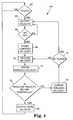
- FIG. 4is a flow diagram illustrating a process for providing inertial effects in an optical, motion translation type screen pointer device according to the present invention.
- FIG. 1shows a simplified representation of a side view of a motion detection arrangement 1 suitable for tracking the movement of a human finger 7 pressed against a surface 5 of a transparent stud 3 , which is made of plastic in one embodiment.
- a motion detection arrangement like that shown in FIG. 1is described in detail in the above-incorporated U.S. Pat. No. 6,057,540 (the '540 patent).
- the operation of motion detection arrangement 1is also summarized below.
- the present inventionis described with reference to the particular optical pointing device arrangement shown in FIG. 1, the techniques described herein are also applicable to other optical pointing devices, including an optical mouse, such as that disclosed in the above-incorporated U.S. patent application Ser. No. 09/052,046, and including an optical pen-like pointing device, such as that disclosed in the above-incorporated U.S. Pat. No. 6,151,015.
- a light source 2which is an LED in one embodiment, emits light that is gathered and focused by lens 4 to illuminate surface 5 .
- Surface 5may be flat, or preferably, have a slight curvature. Curvature aids in enlarging the size of the region of surface 5 that is in focus for the motion detector 9 described below.
- Surface 5may be a glass or other wear resistant coating applied to the end of transparent stud 3 . In one form of the present invention, surface 5 is about ⁇ fraction (3/16) ⁇ to 1 ⁇ 4 of an inch in diameter, and the length of transparent stud 3 ranges from about 3 ⁇ 8 to 3 ⁇ 4 of an inch. Another term that is descriptive of transparent stud 3 is “rod lens”. Opaque barrier 10 keeps stray light from LED 2 from reaching motion detector 9 .
- This conditionis detected within motion detector 9 , and in one embodiment, the production of incremental (X, Y) signals continues, with gradually decreasing magnitudes. This has the effect of continuing the motion of the screen pointer.
- the continued motionis similar to the motion of a screen pointer when a mechanical ball of a track ball is “flicked.”
- motion detector 9appreciates that an image has been acquired, and, in one embodiment, treats that acquisition as though a reset has been performed.
- the incremental coordinates (X, Y)will have the value (0, 0).
- Motion sensor 9uses exactly or substantially the same technique as the imaging and navigation arrangement described in the incorporated Patents.
- the features on fingertip 6are really quite large in comparison, so that magnification is not used in one embodiment.
- an imaging and navigation mechanismis described in the incorporated Patents, a brief overview of the technique is provided below.
- An LED 2which is an IR LED in one embodiment, emits light that is projected by lens 4 onto a region 5 that is part of a work surface 6 to be imaged for navigation.
- motion sensor 9is an integrated circuit (IC) having an array of photo detectors, memory, and arithmetic circuits arranged to implement image correlation and tracking functions described herein and in the incorporated patents.
- An image of the illuminated region 6is projected through an optical window (which may be transparent stud 3 itself) to a package (not shown) of integrated circuit 9 and onto the array of photo detectors.
- Lens 8aids in the projection of the image onto the photo detectors.
- One preferred optical navigation techniqueoptically detects motion by directly imaging as an array of pixels the various particular optical features visible at surface 5 , much as human vision is believed to do.
- IR light reflected from a textured work surface pressed against surface 5is focused onto a suitable array (e.g., 16 ⁇ 16 or 24 ⁇ 24) of photo detectors.
- the responses of the individual photo detectorsare digitized to a suitable resolution (e.g., six or eight bits) and stored as a frame into corresponding locations within an array of memory.
- each pixel in a framecorresponds to one of the photo detectors.
- the overall size of the array of photo detectorsis preferably large enough to receive an image having several features (e.g., ridges in the whorls of skin). In this way, images of such spatial features produce translated patterns of pixel information as fingertip 6 moves.
- the number of photo detectors in the array and the frame rate at which their contents are digitized and capturedcooperate to influence how fast fingertip 6 can be moved over surface 5 and still be tracked. Tracking is accomplished by comparing a newly captured sample frame with a previously captured reference frame to ascertain the direction and amount of movement.
- the entire content of one of the framesis shifted by a distance of one pixel successively in each of the eight directions allowed by a one pixel offset trial shift (one over, one over and one down, one down, one up, one up and one over, one over in the other direction, etc.). That adds up to eight trials. Also, since there might not have been any motion, a ninth trial “null shift” is also used. After each trial shift, those portions of the frames that overlap each other are subtracted on a pixel by pixel basis, and the resulting differences are preferably squared and then summed to form a measure of similarity (correlation) within that region of overlap.
- the trial shift with the least differencecan be taken as an indication of the motion between the two frames. That is, it provides raw movement information that may be scaled and or accumulated to provide display pointer movement information ( ⁇ X and ⁇ Y) of a convenient granularity and at a suitable rate of information exchange.
- Sensor 9automatically detects when fingertip 6 has been removed from surface 5 , by sensing that all or a majority of the pixels in the image have “gone dark.” The process is actually somewhat more complicated than that, as explained below.
- the IR light from the illuminating LED 2no longer reaches the photo detectors in the same quantity that it did previously, if at all; the reflecting surface is too far away or is simply not in view.
- the outputs of the photo detectorsmight be at any level.
- the keyis that the outputs of the photo detectors will be uniform, or nearly so.
- the main reason that the outputs become uniformis that there is no longer a focused image. All of the image features are indistinct and they are each spread out over the entire collection of photo detectors. Therefore, the photo detectors uniformly come to some average level. This is in distinct contrast with the case when there is a focused image. In the focused case, the correlations between frames (recall the one over, one over and one down, etc.) exhibit a distinct phenomenon.
- imagesshould be acquired at a rate sufficient that successive images differ in distance by no more that perhaps a quarter of the width of the array, or 4 pixels for a 16 ⁇ 16 array of photo sensors.
- a finger speed of 50 mm/secis not unreasonable. With 1:1 imaging, this corresponds to a speed at the array of 800 pixels per second.
- a measurement rate of 200 samples per secondis needed. This rate is quite practical, and it may be desirable to operate at several times this rate.
- FIG. 2is a graph illustrating typical velocity profiles for a mechanical pointing device, such as a track ball, and an optical pointing device.
- Graph 20includes a horizontal axis, a vertical axis, curve 24 , and curve 26 .
- the horizontal axis of graph 20represents time, and the vertical axis represents velocity.
- Curve 26illustrates the velocity versus time or velocity profile of a mechanical mouse or track ball when it is “flicked”, or quickly accelerated and then released. The total distance moved is proportional to the area under curve 26 .
- Curve 26is generated from a series of velocity samples 22 .
- curve 26the velocity of the mechanical ball in the track ball initially increases at a near constant rate, with the velocity increase caused by a finger beginning a flicking action on the ball. After the mechanical ball is flicked and released, the velocity of the ball gradually decays to zero. In contrast, for a typical optical pointing device, when a user removes his finger from the device after performing a flicking action, the velocity instantly drops to zero as shown by curve 24 .
- Curves 24 and 26are representative of typical velocity profiles for one type of pointer device movement, and will vary depending upon the exact movement caused by a user. In one form of the present invention, the velocity profile of a mechanical mouse or track ball represented by curve 26 is used as a model in determining an appropriate velocity profile for an optical pointing device with inertial properties.
- FIG. 3is a block diagram illustrating one embodiment of a momentum simulator or emulator for an optical motion translation type screen pointer device that provides inertial effects.
- Momentum simulator 40includes friction simulator or controller 44 , velocity state variable register 46 , and time constant 48 .
- momentum simulator 40 and motion detector 9are integrated into a single IC package.
- momentum simulator 40 and motion detector 9are separate ICs.
- Motion detector 9outputs velocity data for X and Y dimensions as discussed above with reference to FIG. 1 .
- motion detector 9multiplies velocity data by a multiplication factor, thereby normalizing the velocity data.
- the normalized velocity datais output to friction simulator 44 , which, in effect, adds friction to the velocity data, and outputs gradually reduced velocity data.
- the output of friction simulator 44may be coupled to any device that utilizes a screen pointer or cursor, including computers, cell phones, personal digital assistants (PDAs), digital cameras, portable game devices, or any other device using a screen pointer.
- PDAspersonal digital assistants
- the rate at which the velocity data is reduced by friction simulator 44is based on an exponential decay with a time constant specified by the value of time constant 48 .
- the value of time constant 48may be specified by a user.
- Friction simulator 44stores velocity data in velocity state variable register 46 . Momentum simulator 40 is described in further detail below with reference to FIG. 4 .
- FIG. 4is a flow diagram illustrating a process 60 for providing inertial effects in an optical, motion translation type screen pointer device according to the present invention.
- step 62motion detector 9 determines whether fingertip 6 is touching surface 5 . If fingertip 6 is not touching surface 5 , motion detector 9 outputs zero velocity, and continues to sense whether fingertip 6 touches surface 5 . If fingertip 6 is touching surface 5 , motion detector 9 calculates the X and Y components of the velocity of fingertip 6 as discussed above, and, in step 64 , outputs the velocity data or movement data to friction simulator 44 . In step 66 , motion detector 9 senses whether fingertip 6 has been removed from surface 5 .
- motion detector 9continues to output velocity data as represented by step 64 .
- motion detector 9continues to output velocity data representative of the movement.
- the velocity data output by motion detector 9is normalized. In one embodiment, motion detector 9 multiplies the velocity data by 100, and outputs the normalized velocity data to friction simulator 44 . Friction simulator 44 outputs the normalized velocity data without adding friction, since fingertip 6 is still on surface 5 .
- step 68when fingertip 6 is removed from surface 5 , the velocity at the time of removal, or the current velocity data, is stored in register 46 .
- step 70friction simulator 44 decreases the velocity data in cycles by an amount determined by time constant 48 .
- step 74friction simulator 44 stores the reduced velocity data for the current cycle in register 46 .
- step 76friction simulator 44 determines whether the reduced velocity data stored in register 46 is below a specified threshold level. If the reduced velocity data is below the specified threshold level, friction simulator 44 outputs zero velocity in step 80 , and motion detector 9 again waits for fingertip 6 to touch surface 5 as indicated by step 62 .
- step 78friction simulator 44 outputs the reduced velocity data. If fingertip 6 does not re-touch surface 5 (step 72 ), friction simulator 44 continues to gradually reduce the velocity data and output the reduced velocity data (steps 70 , 74 , 76 , and 78 ) until the velocity data is below the specified threshold level. At step 72 , if fingertip 6 re-touches surface 5 , the process jumps to step 64 , where motion detector 9 determines the current velocity of movement and outputs corresponding velocity data.
- Friction simulator 44stores the normalized velocity in register 46 .
- Friction simulator 44decreases the velocity stored in register 46 by 1 percent, stores the decreased velocity (i.e., 0.9900 inches/second) in register 46 , and outputs the decreased velocity.
- friction simulator 44again decreases the velocity stored in register 46 by 1 percent, stores the decreased velocity (i.e., 0.9801 inches/second) in register 46 , and outputs the decreased velocity. Friction simulator 44 continues to decrease the velocity by 1 percent each millisecond until the velocity is below the specified threshold value, at which point friction simulator 44 outputs a value of zero velocity.
- friction simulator 44drives the initial velocity of 1 inch/second to 0.37 inches/second. After two seconds, friction simulator 44 drives the velocity down to 0.14 inches/second. Assuming that the specified threshold value is 0.10 inches/second, friction simulator 44 drives the initial velocity down to zero just after 2 seconds.
- Other values for time constant 48may be chosen to provide a desired level of friction.
- acceleration and deceleration characteristicsmay be explicitly defined by a user. In one embodiment, faster flicks will result in larger initial velocities and longer settling times, and slower flicks will result in smaller initial velocities and shorter settling times.
- the inertial motionmay be stopped at any time by re-touching surface 5 . In one embodiment, the continued inertial movement of the present invention is provided only when a specified minimum acceleration has been provided by a user.
- Friction simulator 44uses the mathematical representation to generate the desired velocity characteristics.
- a usercan enter a “flick factor”, which defines the screen pointer movement when the optical pointing device is flicked. For example, a 1 inch/second flick of the optical pointing device could cause the screen pointer to traverse the screen and slide to a stop.
- a usermay specify that the device is to have no friction, so that when the optical pointing device is flicked, the pointer will continue across the screen until it reaches a screen boundary, or until the user again contacts the pointing device.
- a usermay specify that the device is to provide further acceleration of the screen pointer after a user flicks the optical pointing device. Such further acceleration could not be provided with a simple mechanical track ball, due to the laws of physics. When a track ball has been released, it can not accelerate further unless pushed by a user.
- Any mathematical function or arbitrary curvemay be entered by a user to specify the desired response of the optical pointing device, including functions or curves that eventually result in zero velocity, and functions and curves that result in continued velocity and/or acceleration after a user stops contacting the optical pointing device.
- the continued velocity and/or accelerationcan be overridden by the user by contacting the optical pointing device.
- a usermay exactly specify the desired characteristics of the optical pointing device for each particular application.
- momentum simulator 40may be implemented in hardware, software, firmware, or any combination thereof.
- the implementationmay be via a microprocessor, programmable logic device, or state machine.
- Components of the present inventionmay reside in software on one or more computer-readable mediums.
- the term computer-readable medium as used hereinis defined to include any kind of memory, volatile or non-volatile, such as floppy disks, hard disks, CD-ROMs, flash memory, read-only memory (ROM), and random access memory.
- the desired movement characteristicsmay be implemented in a software driver of a host device (e.g., computer, PDA, digital camera, cell phone, portable game device, etc.) coupled to the optical pointing device.
- a host devicee.g., computer, PDA, digital camera, cell phone, portable game device, etc.
- Embodiments of the present inventionprovide numerous benefits, including the ability to increase the dynamic range of an optical pointing device, which is particularly useful for larger screens. Small hand movements can result in large screen pointer movements. Also, an optical pointing device like that shown in FIG. 1 can be made to feel and operate just like a mechanical track ball, which may be desirable to individuals who are familiar with operating such mechanical pointing devices.
Landscapes
- Engineering & Computer Science (AREA)
- General Engineering & Computer Science (AREA)
- Theoretical Computer Science (AREA)
- Human Computer Interaction (AREA)
- Physics & Mathematics (AREA)
- General Physics & Mathematics (AREA)
- Position Input By Displaying (AREA)
Abstract
Description
Claims (39)
Priority Applications (4)
| Application Number | Priority Date | Filing Date | Title |
|---|---|---|---|
| US09/810,745US6621483B2 (en) | 2001-03-16 | 2001-03-16 | Optical screen pointing device with inertial properties |
| GB0201893AGB2374409B (en) | 2001-03-16 | 2002-01-28 | Optical screen pointing device |
| DE10211340ADE10211340A1 (en) | 2001-03-16 | 2002-03-14 | Optical screen pointing device with inertia properties |
| JP2002074128AJP2002278693A (en) | 2001-03-16 | 2002-03-18 | Optical pointing device showing inertial effect |
Applications Claiming Priority (1)
| Application Number | Priority Date | Filing Date | Title |
|---|---|---|---|
| US09/810,745US6621483B2 (en) | 2001-03-16 | 2001-03-16 | Optical screen pointing device with inertial properties |
Publications (2)
| Publication Number | Publication Date |
|---|---|
| US20020130839A1 US20020130839A1 (en) | 2002-09-19 |
| US6621483B2true US6621483B2 (en) | 2003-09-16 |
Family
ID=25204596
Family Applications (1)
| Application Number | Title | Priority Date | Filing Date |
|---|---|---|---|
| US09/810,745Expired - LifetimeUS6621483B2 (en) | 2001-03-16 | 2001-03-16 | Optical screen pointing device with inertial properties |
Country Status (4)
| Country | Link |
|---|---|
| US (1) | US6621483B2 (en) |
| JP (1) | JP2002278693A (en) |
| DE (1) | DE10211340A1 (en) |
| GB (1) | GB2374409B (en) |
Cited By (53)
| Publication number | Priority date | Publication date | Assignee | Title |
|---|---|---|---|---|
| US20020130273A1 (en)* | 2001-03-19 | 2002-09-19 | Gordon Gary B. | Impedance sensing screen pointing device |
| US20030184520A1 (en)* | 2002-03-28 | 2003-10-02 | Patrick Wei | Mouse with optical buttons |
| US6762751B2 (en)* | 2001-12-17 | 2004-07-13 | Behavior Tech Computer Corporation | Optical pointing device |
| US20040227954A1 (en)* | 2003-05-16 | 2004-11-18 | Tong Xie | Interferometer based navigation device |
| US20050024623A1 (en)* | 2003-07-30 | 2005-02-03 | Tong Xie | Method and device for optical navigation |
| US20050128182A1 (en)* | 2003-12-12 | 2005-06-16 | Gordon Gary B. | Apparatus and method for controlling a screen pointer |
| US20050179667A1 (en)* | 2002-04-03 | 2005-08-18 | Leif Nilsson | Method of navigating in a virtual three-dimensional environment and an electronic device employing such method |
| US20050259097A1 (en)* | 2004-05-21 | 2005-11-24 | Silicon Light Machines Corporation | Optical positioning device using different combinations of interlaced photosensitive elements |
| US20050259078A1 (en)* | 2004-05-21 | 2005-11-24 | Silicon Light Machines Corporation | Optical positioning device with multi-row detector array |
| US20050258346A1 (en)* | 2004-05-21 | 2005-11-24 | Silicon Light Machines Corporation | Optical positioning device resistant to speckle fading |
| US20050259098A1 (en)* | 2004-05-21 | 2005-11-24 | Silicon Light Machines Corporation | Optical positioning device using telecentric imaging |
| US20050258347A1 (en)* | 2004-05-21 | 2005-11-24 | Silicon Light Machines Corporation | Optical positioning device having shaped illumination |
| US20050259267A1 (en)* | 2004-05-21 | 2005-11-24 | Silicon Light Machines Corporation | Speckle sizing and sensor dimensions in optical positioning device |
| US20060091301A1 (en)* | 2004-10-29 | 2006-05-04 | Silicon Light Machines Corporation | Two-dimensional motion sensor |
| US20060106319A1 (en)* | 2004-11-12 | 2006-05-18 | Silicon Light Machines Corporation | Signal processing method for use with an optical navigation system |
| US20060109241A1 (en)* | 2004-11-19 | 2006-05-25 | Dueweke Michael J | Dense multi-axis array for motion sensing |
| US20060118743A1 (en)* | 2004-12-02 | 2006-06-08 | Silicon Light Machines Corporation | Signal processing method for optical sensors |
| US20060170653A1 (en)* | 2005-02-01 | 2006-08-03 | Eastman Kodak Company | Pointing device with switch |
| US20070018970A1 (en)* | 2000-12-22 | 2007-01-25 | Logitech Europe S.A. | Optical slider for input devices |
| US20070090279A1 (en)* | 2005-08-16 | 2007-04-26 | Shalini Venkatesh | System and method for an optical navigation device configured to generate navigation information through an optically transparent layer and to have skating functionality |
| US20070143383A1 (en)* | 2005-12-16 | 2007-06-21 | Silicon Light Machines Corporation | Signal averaging circuit and method for sample averaging |
| US20070138377A1 (en)* | 2005-12-16 | 2007-06-21 | Silicon Light Machines Corporation | Optical navigation system having a filter-window to seal an enclosure thereof |
| US20070139381A1 (en)* | 2005-12-20 | 2007-06-21 | Spurlock Brett A | Speckle navigation system |
| US20070165207A1 (en)* | 2006-01-03 | 2007-07-19 | Silicon Light Machines Corporation | Method for determining motion using a velocity predictor |
| US7268341B2 (en) | 2004-05-21 | 2007-09-11 | Silicon Light Machines Corporation | Optical position sensing device including interlaced groups of photosensitive elements |
| US20070230525A1 (en)* | 2006-03-31 | 2007-10-04 | Steven Sanders | Eye-safe laser navigation sensor |
| US7297912B1 (en) | 2006-03-27 | 2007-11-20 | Silicon Light Machines Corporation | Circuit and method for reducing power consumption in an optical navigation system having redundant arrays |
| US20080007526A1 (en)* | 2006-07-10 | 2008-01-10 | Yansun Xu | Optical navigation sensor with variable tracking resolution |
| US20080012029A1 (en)* | 2004-08-13 | 2008-01-17 | Schranz Paul S | Light Emitting and Image Sensing Device and Apparatus |
| US20080150906A1 (en)* | 2006-12-22 | 2008-06-26 | Grivna Edward L | Multi-axial touch-sensor device with multi-touch resolution |
| US7492445B1 (en) | 2006-06-05 | 2009-02-17 | Cypress Semiconductor Corporation | Method and apparatus for robust velocity prediction |
| US20090059206A1 (en)* | 2007-08-30 | 2009-03-05 | Churchill David L | Optical Linear and Rotation Displacement Sensor |
| US20090135140A1 (en)* | 2007-11-27 | 2009-05-28 | Logitech Europe S.A. | System and method for accurate lift-detection of an input device |
| US7567235B2 (en) | 2005-12-12 | 2009-07-28 | Cypress Semiconductor Corporation | Self-aligning optical sensor package |
| US20100071967A1 (en)* | 2008-09-23 | 2010-03-25 | Avago Technologies Ecbu Ip (Singapore) Pte. Ltd. | Optical finger navigation device with integrated tactile switch |
| US7721609B2 (en) | 2006-03-31 | 2010-05-25 | Cypress Semiconductor Corporation | Method and apparatus for sensing the force with which a button is pressed |
| US7723659B1 (en) | 2008-10-10 | 2010-05-25 | Cypress Semiconductor Corporation | System and method for screening semiconductor lasers |
| US7742514B1 (en) | 2006-10-31 | 2010-06-22 | Cypress Semiconductor Corporation | Laser navigation sensor |
| US7755604B2 (en) | 2006-06-19 | 2010-07-13 | Cypress Semiconductor Corporation | Optical navigation sensor with tracking and lift detection for optically transparent contact surfaces |
| US7872639B2 (en) | 2005-06-30 | 2011-01-18 | Logitech Europe S.A. | Optical displacement detection over varied surfaces |
| US20110022033A1 (en)* | 2005-12-28 | 2011-01-27 | Depuy Products, Inc. | System and Method for Wearable User Interface in Computer Assisted Surgery |
| US7884801B1 (en) | 2006-02-16 | 2011-02-08 | Cypress Semiconductor Corporation | Circuit and method for determining motion with redundant comb-arrays |
| US8031176B1 (en) | 2008-01-22 | 2011-10-04 | Cypress Semiconductor Corporation | Optical navigation system using a single-package motion sensor |
| US8217334B1 (en) | 2008-12-24 | 2012-07-10 | Cypress Semiconductor Corporation | Optical navigation sensor including a spatial frequency filter |
| US8259069B1 (en) | 2008-01-11 | 2012-09-04 | Cypress Semiconductor Corporation | Speckle-based optical navigation on curved tracking surface |
| US8263921B2 (en) | 2007-08-06 | 2012-09-11 | Cypress Semiconductor Corporation | Processing methods for speckle-based motion sensing |
| US20120242620A1 (en)* | 2011-03-22 | 2012-09-27 | Research In Motion Limited | Combined optical navigation and button |
| US8314774B1 (en) | 2007-07-09 | 2012-11-20 | Cypress Semiconductor Corporation | Method and apparatus for quasi-3D tracking using 2D optical motion sensors |
| US8541728B1 (en) | 2008-09-30 | 2013-09-24 | Cypress Semiconductor Corporation | Signal monitoring and control system for an optical navigation sensor |
| US8711096B1 (en) | 2009-03-27 | 2014-04-29 | Cypress Semiconductor Corporation | Dual protocol input device |
| US8896553B1 (en) | 2011-11-30 | 2014-11-25 | Cypress Semiconductor Corporation | Hybrid sensor module |
| US9103658B2 (en) | 2011-06-16 | 2015-08-11 | Cypress Semiconductor Corporation | Optical navigation module with capacitive sensor |
| US10073610B2 (en) | 2004-08-06 | 2018-09-11 | Qualcomm Incorporated | Bounding box gesture recognition on a touch detecting interactive display |
Families Citing this family (48)
| Publication number | Priority date | Publication date | Assignee | Title |
|---|---|---|---|---|
| US7084859B1 (en) | 1992-09-18 | 2006-08-01 | Pryor Timothy R | Programmable tactile touch screen displays and man-machine interfaces for improved vehicle instrumentation and telematics |
| US9513744B2 (en)* | 1994-08-15 | 2016-12-06 | Apple Inc. | Control systems employing novel physical controls and touch screens |
| US20090273574A1 (en)* | 1995-06-29 | 2009-11-05 | Pryor Timothy R | Programmable tactile touch screen displays and man-machine interfaces for improved vehicle instrumentation and telematics |
| US8228305B2 (en) | 1995-06-29 | 2012-07-24 | Apple Inc. | Method for providing human input to a computer |
| GB9722766D0 (en) | 1997-10-28 | 1997-12-24 | British Telecomm | Portable computers |
| US9239673B2 (en) | 1998-01-26 | 2016-01-19 | Apple Inc. | Gesturing with a multipoint sensing device |
| US7808479B1 (en) | 2003-09-02 | 2010-10-05 | Apple Inc. | Ambidextrous mouse |
| US7614008B2 (en) | 2004-07-30 | 2009-11-03 | Apple Inc. | Operation of a computer with touch screen interface |
| US9292111B2 (en) | 1998-01-26 | 2016-03-22 | Apple Inc. | Gesturing with a multipoint sensing device |
| US8479122B2 (en) | 2004-07-30 | 2013-07-02 | Apple Inc. | Gestures for touch sensitive input devices |
| US8482535B2 (en) | 1999-11-08 | 2013-07-09 | Apple Inc. | Programmable tactile touch screen displays and man-machine interfaces for improved vehicle instrumentation and telematics |
| US20080122799A1 (en)* | 2001-02-22 | 2008-05-29 | Pryor Timothy R | Human interfaces for vehicles, homes, and other applications |
| US8576199B1 (en) | 2000-02-22 | 2013-11-05 | Apple Inc. | Computer control systems |
| US20080024463A1 (en)* | 2001-02-22 | 2008-01-31 | Timothy Pryor | Reconfigurable tactile control display applications |
| US6809723B2 (en)* | 2001-05-14 | 2004-10-26 | Agilent Technologies, Inc. | Pushbutton optical screen pointing device |
| US8300042B2 (en) | 2001-06-05 | 2012-10-30 | Microsoft Corporation | Interactive video display system using strobed light |
| US8035612B2 (en) | 2002-05-28 | 2011-10-11 | Intellectual Ventures Holding 67 Llc | Self-contained interactive video display system |
| US7259747B2 (en) | 2001-06-05 | 2007-08-21 | Reactrix Systems, Inc. | Interactive video display system |
| US7348963B2 (en)* | 2002-05-28 | 2008-03-25 | Reactrix Systems, Inc. | Interactive video display system |
| US7710391B2 (en) | 2002-05-28 | 2010-05-04 | Matthew Bell | Processing an image utilizing a spatially varying pattern |
| US7656393B2 (en) | 2005-03-04 | 2010-02-02 | Apple Inc. | Electronic device having display and surrounding touch sensitive bezel for user interface and control |
| US11275405B2 (en) | 2005-03-04 | 2022-03-15 | Apple Inc. | Multi-functional hand-held device |
| US7358963B2 (en)* | 2002-09-09 | 2008-04-15 | Apple Inc. | Mouse having an optically-based scrolling feature |
| WO2004055776A1 (en) | 2002-12-13 | 2004-07-01 | Reactrix Systems | Interactive directed light/sound system |
| US6888988B2 (en) | 2003-03-14 | 2005-05-03 | Agilent Technologies, Inc. | Small form factor all-polymer optical device with integrated dual beam path based on total internal reflection optical turn |
| US7587072B2 (en)* | 2003-08-22 | 2009-09-08 | Authentec, Inc. | System for and method of generating rotational inputs |
| WO2005041579A2 (en) | 2003-10-24 | 2005-05-06 | Reactrix Systems, Inc. | Method and system for processing captured image information in an interactive video display system |
| CN102034197A (en) | 2003-10-24 | 2011-04-27 | 瑞克楚斯系统公司 | Method and system for managing an interactive video display system |
| US7743348B2 (en)* | 2004-06-30 | 2010-06-22 | Microsoft Corporation | Using physical objects to adjust attributes of an interactive display application |
| US8381135B2 (en) | 2004-07-30 | 2013-02-19 | Apple Inc. | Proximity detector in handheld device |
| US20100231506A1 (en)* | 2004-09-07 | 2010-09-16 | Timothy Pryor | Control of appliances, kitchen and home |
| US7761814B2 (en)* | 2004-09-13 | 2010-07-20 | Microsoft Corporation | Flick gesture |
| NO20044073D0 (en)* | 2004-09-27 | 2004-09-27 | Isak Engquist | Information Processing System and Procedures |
| US7925996B2 (en)* | 2004-11-18 | 2011-04-12 | Microsoft Corporation | Method and system for providing multiple input connecting user interface |
| US9128519B1 (en)* | 2005-04-15 | 2015-09-08 | Intellectual Ventures Holding 67 Llc | Method and system for state-based control of objects |
| US8081822B1 (en) | 2005-05-31 | 2011-12-20 | Intellectual Ventures Holding 67 Llc | System and method for sensing a feature of an object in an interactive video display |
| US7710397B2 (en) | 2005-06-03 | 2010-05-04 | Apple Inc. | Mouse with improved input mechanisms using touch sensors |
| US8098277B1 (en) | 2005-12-02 | 2012-01-17 | Intellectual Ventures Holding 67 Llc | Systems and methods for communication between a reactive video system and a mobile communication device |
| US8077147B2 (en) | 2005-12-30 | 2011-12-13 | Apple Inc. | Mouse with optical sensing surface |
| US7844915B2 (en) | 2007-01-07 | 2010-11-30 | Apple Inc. | Application programming interfaces for scrolling operations |
| EP2017702A1 (en)* | 2007-07-13 | 2009-01-21 | Flinglab AB | Method for controlling the movement of a cursor |
| JP5430572B2 (en) | 2007-09-14 | 2014-03-05 | インテレクチュアル ベンチャーズ ホールディング 67 エルエルシー | Gesture-based user interaction processing |
| US8159682B2 (en) | 2007-11-12 | 2012-04-17 | Intellectual Ventures Holding 67 Llc | Lens system |
| US8259163B2 (en) | 2008-03-07 | 2012-09-04 | Intellectual Ventures Holding 67 Llc | Display with built in 3D sensing |
| US8595218B2 (en) | 2008-06-12 | 2013-11-26 | Intellectual Ventures Holding 67 Llc | Interactive display management systems and methods |
| JP5552772B2 (en)* | 2009-08-26 | 2014-07-16 | ソニー株式会社 | Information processing apparatus, information processing method, and computer program |
| JP5461335B2 (en)* | 2010-07-28 | 2014-04-02 | 京セラ株式会社 | Electronics |
| KR20140137656A (en)* | 2013-05-23 | 2014-12-03 | 삼성전자주식회사 | Method for scanning data and an electronic device thereof |
Citations (8)
| Publication number | Priority date | Publication date | Assignee | Title |
|---|---|---|---|---|
| US5578813A (en) | 1995-03-02 | 1996-11-26 | Allen; Ross R. | Freehand image scanning device which compensates for non-linear movement |
| US5786804A (en) | 1995-10-06 | 1998-07-28 | Hewlett-Packard Company | Method and system for tracking attitude |
| US5825352A (en)* | 1996-01-04 | 1998-10-20 | Logitech, Inc. | Multiple fingers contact sensing method for emulating mouse buttons and mouse operations on a touch sensor pad |
| US5994710A (en) | 1998-04-30 | 1999-11-30 | Hewlett-Packard Company | Scanning mouse for a computer system |
| US6057540A (en) | 1998-04-30 | 2000-05-02 | Hewlett-Packard Co | Mouseless optical and position translation type screen pointer control for a computer system |
| US6151015A (en) | 1998-04-27 | 2000-11-21 | Agilent Technologies | Pen like computer pointing device |
| US6424407B1 (en)* | 1998-03-09 | 2002-07-23 | Otm Technologies Ltd. | Optical translation measurement |
| US6452683B1 (en)* | 1998-03-09 | 2002-09-17 | Otm Technologies Ltd. | Optical translation measurement |
Family Cites Families (3)
| Publication number | Priority date | Publication date | Assignee | Title |
|---|---|---|---|---|
| JPS5994134A (en)* | 1982-11-20 | 1984-05-30 | Matsushita Electric Ind Co Ltd | Input device |
| JPH11161413A (en)* | 1997-11-28 | 1999-06-18 | Sony Corp | Input device |
| JP2001067180A (en)* | 1999-08-30 | 2001-03-16 | Matsushita Electric Ind Co Ltd | Optical pointing input device |
- 2001
- 2001-03-16USUS09/810,745patent/US6621483B2/ennot_activeExpired - Lifetime
- 2002
- 2002-01-28GBGB0201893Apatent/GB2374409B/ennot_activeExpired - Fee Related
- 2002-03-14DEDE10211340Apatent/DE10211340A1/ennot_activeWithdrawn
- 2002-03-18JPJP2002074128Apatent/JP2002278693A/ennot_activeWithdrawn
Patent Citations (9)
| Publication number | Priority date | Publication date | Assignee | Title |
|---|---|---|---|---|
| US5578813A (en) | 1995-03-02 | 1996-11-26 | Allen; Ross R. | Freehand image scanning device which compensates for non-linear movement |
| US5644139A (en) | 1995-03-02 | 1997-07-01 | Allen; Ross R. | Navigation technique for detecting movement of navigation sensors relative to an object |
| US5786804A (en) | 1995-10-06 | 1998-07-28 | Hewlett-Packard Company | Method and system for tracking attitude |
| US5825352A (en)* | 1996-01-04 | 1998-10-20 | Logitech, Inc. | Multiple fingers contact sensing method for emulating mouse buttons and mouse operations on a touch sensor pad |
| US6424407B1 (en)* | 1998-03-09 | 2002-07-23 | Otm Technologies Ltd. | Optical translation measurement |
| US6452683B1 (en)* | 1998-03-09 | 2002-09-17 | Otm Technologies Ltd. | Optical translation measurement |
| US6151015A (en) | 1998-04-27 | 2000-11-21 | Agilent Technologies | Pen like computer pointing device |
| US5994710A (en) | 1998-04-30 | 1999-11-30 | Hewlett-Packard Company | Scanning mouse for a computer system |
| US6057540A (en) | 1998-04-30 | 2000-05-02 | Hewlett-Packard Co | Mouseless optical and position translation type screen pointer control for a computer system |
Non-Patent Citations (1)
| Title |
|---|
| "Seeing Eye" Mouse for a Computer System, U.S. patent application Ser. No. 09/052,046, filed Mar. 30, 1998. |
Cited By (82)
| Publication number | Priority date | Publication date | Assignee | Title |
|---|---|---|---|---|
| US20070018970A1 (en)* | 2000-12-22 | 2007-01-25 | Logitech Europe S.A. | Optical slider for input devices |
| US20020130273A1 (en)* | 2001-03-19 | 2002-09-19 | Gordon Gary B. | Impedance sensing screen pointing device |
| US7184026B2 (en)* | 2001-03-19 | 2007-02-27 | Avago Technologies Ecbu Ip (Singapore) Pte. Ltd. | Impedance sensing screen pointing device |
| US6762751B2 (en)* | 2001-12-17 | 2004-07-13 | Behavior Tech Computer Corporation | Optical pointing device |
| US20030184520A1 (en)* | 2002-03-28 | 2003-10-02 | Patrick Wei | Mouse with optical buttons |
| US20050179667A1 (en)* | 2002-04-03 | 2005-08-18 | Leif Nilsson | Method of navigating in a virtual three-dimensional environment and an electronic device employing such method |
| US20040227954A1 (en)* | 2003-05-16 | 2004-11-18 | Tong Xie | Interferometer based navigation device |
| US20050024623A1 (en)* | 2003-07-30 | 2005-02-03 | Tong Xie | Method and device for optical navigation |
| US7321359B2 (en) | 2003-07-30 | 2008-01-22 | Avago Technologies Ecbu Ip (Singapore) Pte. Ltd. | Method and device for optical navigation |
| US7167162B2 (en) | 2003-12-12 | 2007-01-23 | Avago Technologies Ecbu Ip (Singapore) Pte. Ltd. | Apparatus and method for controlling a screen pointer |
| US20050128182A1 (en)* | 2003-12-12 | 2005-06-16 | Gordon Gary B. | Apparatus and method for controlling a screen pointer |
| US20050259097A1 (en)* | 2004-05-21 | 2005-11-24 | Silicon Light Machines Corporation | Optical positioning device using different combinations of interlaced photosensitive elements |
| US20050258346A1 (en)* | 2004-05-21 | 2005-11-24 | Silicon Light Machines Corporation | Optical positioning device resistant to speckle fading |
| US7268341B2 (en) | 2004-05-21 | 2007-09-11 | Silicon Light Machines Corporation | Optical position sensing device including interlaced groups of photosensitive elements |
| US7042575B2 (en) | 2004-05-21 | 2006-05-09 | Silicon Light Machines Corporation | Speckle sizing and sensor dimensions in optical positioning device |
| US7285766B2 (en) | 2004-05-21 | 2007-10-23 | Silicon Light Machines Corporation | Optical positioning device having shaped illumination |
| US20050259267A1 (en)* | 2004-05-21 | 2005-11-24 | Silicon Light Machines Corporation | Speckle sizing and sensor dimensions in optical positioning device |
| US8345003B1 (en) | 2004-05-21 | 2013-01-01 | Cypress Semiconductor Corporation | Optical positioning device using telecentric imaging |
| US7773070B2 (en) | 2004-05-21 | 2010-08-10 | Cypress Semiconductor Corporation | Optical positioning device using telecentric imaging |
| US20050259078A1 (en)* | 2004-05-21 | 2005-11-24 | Silicon Light Machines Corporation | Optical positioning device with multi-row detector array |
| US20050258347A1 (en)* | 2004-05-21 | 2005-11-24 | Silicon Light Machines Corporation | Optical positioning device having shaped illumination |
| US20050259098A1 (en)* | 2004-05-21 | 2005-11-24 | Silicon Light Machines Corporation | Optical positioning device using telecentric imaging |
| US10073610B2 (en) | 2004-08-06 | 2018-09-11 | Qualcomm Incorporated | Bounding box gesture recognition on a touch detecting interactive display |
| US20090166643A1 (en)* | 2004-08-13 | 2009-07-02 | Paul Steven Schranz | Light emitting and image sensing device and apparatus |
| US7521719B2 (en) | 2004-08-13 | 2009-04-21 | Paul Steven Schranz | Light emitting and image sensing device and apparatus |
| US20080012029A1 (en)* | 2004-08-13 | 2008-01-17 | Schranz Paul S | Light Emitting and Image Sensing Device and Apparatus |
| US7459671B2 (en) | 2004-10-29 | 2008-12-02 | Cypress Semiconductor Corporation | Two-dimensional motion sensor |
| US7138620B2 (en) | 2004-10-29 | 2006-11-21 | Silicon Light Machines Corporation | Two-dimensional motion sensor |
| US20060091301A1 (en)* | 2004-10-29 | 2006-05-04 | Silicon Light Machines Corporation | Two-dimensional motion sensor |
| US20060106319A1 (en)* | 2004-11-12 | 2006-05-18 | Silicon Light Machines Corporation | Signal processing method for use with an optical navigation system |
| US7248345B2 (en) | 2004-11-12 | 2007-07-24 | Silicon Light Machines Corporation | Signal processing method for use with an optical navigation system |
| US7405389B2 (en) | 2004-11-19 | 2008-07-29 | Silicon Light Machines Corporation | Dense multi-axis array for motion sensing |
| US20060109241A1 (en)* | 2004-11-19 | 2006-05-25 | Dueweke Michael J | Dense multi-axis array for motion sensing |
| US7435942B2 (en) | 2004-12-02 | 2008-10-14 | Cypress Semiconductor Corporation | Signal processing method for optical sensors |
| US20060118743A1 (en)* | 2004-12-02 | 2006-06-08 | Silicon Light Machines Corporation | Signal processing method for optical sensors |
| US20060170653A1 (en)* | 2005-02-01 | 2006-08-03 | Eastman Kodak Company | Pointing device with switch |
| US7898524B2 (en) | 2005-06-30 | 2011-03-01 | Logitech Europe S.A. | Optical displacement detection over varied surfaces |
| US7872639B2 (en) | 2005-06-30 | 2011-01-18 | Logitech Europe S.A. | Optical displacement detection over varied surfaces |
| US7399954B2 (en)* | 2005-08-16 | 2008-07-15 | Avago Technologies Ecbu Ip Pte Ltd | System and method for an optical navigation device configured to generate navigation information through an optically transparent layer and to have skating functionality |
| US20070090279A1 (en)* | 2005-08-16 | 2007-04-26 | Shalini Venkatesh | System and method for an optical navigation device configured to generate navigation information through an optically transparent layer and to have skating functionality |
| US7567235B2 (en) | 2005-12-12 | 2009-07-28 | Cypress Semiconductor Corporation | Self-aligning optical sensor package |
| US20070143383A1 (en)* | 2005-12-16 | 2007-06-21 | Silicon Light Machines Corporation | Signal averaging circuit and method for sample averaging |
| US20070138377A1 (en)* | 2005-12-16 | 2007-06-21 | Silicon Light Machines Corporation | Optical navigation system having a filter-window to seal an enclosure thereof |
| US7765251B2 (en) | 2005-12-16 | 2010-07-27 | Cypress Semiconductor Corporation | Signal averaging circuit and method for sample averaging |
| US8471191B2 (en) | 2005-12-16 | 2013-06-25 | Cypress Semiconductor Corporation | Optical navigation system having a filter-window to seal an enclosure thereof |
| US8558163B2 (en) | 2005-12-16 | 2013-10-15 | Cypress Semiconductor Corporation | Optical navigation system having a filter-window to seal an enclosure thereof |
| US20070139381A1 (en)* | 2005-12-20 | 2007-06-21 | Spurlock Brett A | Speckle navigation system |
| US7737948B2 (en) | 2005-12-20 | 2010-06-15 | Cypress Semiconductor Corporation | Speckle navigation system |
| US20110022033A1 (en)* | 2005-12-28 | 2011-01-27 | Depuy Products, Inc. | System and Method for Wearable User Interface in Computer Assisted Surgery |
| US7298460B2 (en) | 2006-01-03 | 2007-11-20 | Silicon Light Machines Corporation | Method for determining motion using a velocity predictor |
| US20070165207A1 (en)* | 2006-01-03 | 2007-07-19 | Silicon Light Machines Corporation | Method for determining motion using a velocity predictor |
| US7884801B1 (en) | 2006-02-16 | 2011-02-08 | Cypress Semiconductor Corporation | Circuit and method for determining motion with redundant comb-arrays |
| US8547336B1 (en) | 2006-02-16 | 2013-10-01 | Cypress Semiconductor Corporation | Circuit and method for determining motion with redundant comb-arrays |
| US7297912B1 (en) | 2006-03-27 | 2007-11-20 | Silicon Light Machines Corporation | Circuit and method for reducing power consumption in an optical navigation system having redundant arrays |
| US7809035B2 (en) | 2006-03-31 | 2010-10-05 | Cypress Semiconductor Corporation | Eye-safe laser navigation sensor |
| US7721609B2 (en) | 2006-03-31 | 2010-05-25 | Cypress Semiconductor Corporation | Method and apparatus for sensing the force with which a button is pressed |
| US20070230525A1 (en)* | 2006-03-31 | 2007-10-04 | Steven Sanders | Eye-safe laser navigation sensor |
| US7492445B1 (en) | 2006-06-05 | 2009-02-17 | Cypress Semiconductor Corporation | Method and apparatus for robust velocity prediction |
| US7755604B2 (en) | 2006-06-19 | 2010-07-13 | Cypress Semiconductor Corporation | Optical navigation sensor with tracking and lift detection for optically transparent contact surfaces |
| US7728816B2 (en) | 2006-07-10 | 2010-06-01 | Cypress Semiconductor Corporation | Optical navigation sensor with variable tracking resolution |
| US20080007526A1 (en)* | 2006-07-10 | 2008-01-10 | Yansun Xu | Optical navigation sensor with variable tracking resolution |
| US7742514B1 (en) | 2006-10-31 | 2010-06-22 | Cypress Semiconductor Corporation | Laser navigation sensor |
| US20080150906A1 (en)* | 2006-12-22 | 2008-06-26 | Grivna Edward L | Multi-axial touch-sensor device with multi-touch resolution |
| US8072429B2 (en) | 2006-12-22 | 2011-12-06 | Cypress Semiconductor Corporation | Multi-axial touch-sensor device with multi-touch resolution |
| US8314774B1 (en) | 2007-07-09 | 2012-11-20 | Cypress Semiconductor Corporation | Method and apparatus for quasi-3D tracking using 2D optical motion sensors |
| US8263921B2 (en) | 2007-08-06 | 2012-09-11 | Cypress Semiconductor Corporation | Processing methods for speckle-based motion sensing |
| US20090059206A1 (en)* | 2007-08-30 | 2009-03-05 | Churchill David L | Optical Linear and Rotation Displacement Sensor |
| US7952721B2 (en) | 2007-08-30 | 2011-05-31 | Microstrain, Inc. | Optical linear and rotation displacement sensor |
| US20090135140A1 (en)* | 2007-11-27 | 2009-05-28 | Logitech Europe S.A. | System and method for accurate lift-detection of an input device |
| US8259069B1 (en) | 2008-01-11 | 2012-09-04 | Cypress Semiconductor Corporation | Speckle-based optical navigation on curved tracking surface |
| US8669940B1 (en) | 2008-01-22 | 2014-03-11 | Cypress Semiconductor Corporation | Optical navigation system using a single-package motion sensor |
| US8031176B1 (en) | 2008-01-22 | 2011-10-04 | Cypress Semiconductor Corporation | Optical navigation system using a single-package motion sensor |
| US20100071967A1 (en)* | 2008-09-23 | 2010-03-25 | Avago Technologies Ecbu Ip (Singapore) Pte. Ltd. | Optical finger navigation device with integrated tactile switch |
| US8212776B2 (en) | 2008-09-23 | 2012-07-03 | Avago Technologies Ecbu Ip (Singapore) Pte. Ltd. | Optical finger navigation device with integrated tactile switch |
| US8541728B1 (en) | 2008-09-30 | 2013-09-24 | Cypress Semiconductor Corporation | Signal monitoring and control system for an optical navigation sensor |
| US8541727B1 (en) | 2008-09-30 | 2013-09-24 | Cypress Semiconductor Corporation | Signal monitoring and control system for an optical navigation sensor |
| US7723659B1 (en) | 2008-10-10 | 2010-05-25 | Cypress Semiconductor Corporation | System and method for screening semiconductor lasers |
| US8217334B1 (en) | 2008-12-24 | 2012-07-10 | Cypress Semiconductor Corporation | Optical navigation sensor including a spatial frequency filter |
| US8711096B1 (en) | 2009-03-27 | 2014-04-29 | Cypress Semiconductor Corporation | Dual protocol input device |
| US20120242620A1 (en)* | 2011-03-22 | 2012-09-27 | Research In Motion Limited | Combined optical navigation and button |
| US9103658B2 (en) | 2011-06-16 | 2015-08-11 | Cypress Semiconductor Corporation | Optical navigation module with capacitive sensor |
| US8896553B1 (en) | 2011-11-30 | 2014-11-25 | Cypress Semiconductor Corporation | Hybrid sensor module |
Also Published As
| Publication number | Publication date |
|---|---|
| GB0201893D0 (en) | 2002-03-13 |
| GB2374409B (en) | 2005-02-02 |
| GB2374409A (en) | 2002-10-16 |
| DE10211340A1 (en) | 2002-10-02 |
| JP2002278693A (en) | 2002-09-27 |
| US20020130839A1 (en) | 2002-09-19 |
Similar Documents
| Publication | Publication Date | Title |
|---|---|---|
| US6621483B2 (en) | Optical screen pointing device with inertial properties | |
| US6977645B2 (en) | Portable electronic device with mouse-like capabilities | |
| US6795056B2 (en) | System and method for reducing power consumption in an optical screen pointing device | |
| KR102335132B1 (en) | Multi-modal gesture based interactive system and method using one single sensing system | |
| CN103529942B (en) | The input of gesture based on contact-free | |
| US6791531B1 (en) | Device and method for cursor motion control calibration and object selection | |
| US6151015A (en) | Pen like computer pointing device | |
| US6770863B2 (en) | Apparatus and method for three-dimensional relative movement sensing | |
| US20070018966A1 (en) | Predicted object location | |
| US20040234107A1 (en) | System and method for optically detecting a click event | |
| US20080030458A1 (en) | Inertial input apparatus and method with optical motion state detection | |
| JPH11345076A (en) | Screen pointer position control device | |
| WO2003105074A2 (en) | Apparatus and method for inputting data | |
| US20050128182A1 (en) | Apparatus and method for controlling a screen pointer | |
| US20030184520A1 (en) | Mouse with optical buttons | |
| CN104142739B (en) | Laser point tracking system and method based on optical mouse sensing array | |
| US7184026B2 (en) | Impedance sensing screen pointing device | |
| CN2660590Y (en) | pointer input device |
Legal Events
| Date | Code | Title | Description |
|---|---|---|---|
| AS | Assignment | Owner name:AGILENT TECHNOLOGIES, COLORADO Free format text:ASSIGNMENT OF ASSIGNORS INTEREST;ASSIGNORS:WALLACE, HUGH;GORDON, GARY B.;REEL/FRAME:011897/0125;SIGNING DATES FROM 20010316 TO 20010319 | |
| STCF | Information on status: patent grant | Free format text:PATENTED CASE | |
| AS | Assignment | Owner name:AVAGO TECHNOLOGIES GENERAL IP PTE. LTD., SINGAPORE Free format text:ASSIGNMENT OF ASSIGNORS INTEREST;ASSIGNOR:AGILENT TECHNOLOGIES, INC.;REEL/FRAME:017207/0020 Effective date:20051201 | |
| AS | Assignment | Owner name:AVAGO TECHNOLOGIES ECBU IP (SINGAPORE) PTE. LTD., SINGAPORE Free format text:ASSIGNMENT OF ASSIGNORS INTEREST;ASSIGNOR:AVAGO TECHNOLOGIES GENERAL IP (SINGAPORE) PTE. LTD.;REEL/FRAME:017675/0518 Effective date:20060127 Owner name:AVAGO TECHNOLOGIES ECBU IP (SINGAPORE) PTE. LTD.,S Free format text:ASSIGNMENT OF ASSIGNORS INTEREST;ASSIGNOR:AVAGO TECHNOLOGIES GENERAL IP (SINGAPORE) PTE. LTD.;REEL/FRAME:017675/0518 Effective date:20060127 Owner name:AVAGO TECHNOLOGIES ECBU IP (SINGAPORE) PTE. LTD., Free format text:ASSIGNMENT OF ASSIGNORS INTEREST;ASSIGNOR:AVAGO TECHNOLOGIES GENERAL IP (SINGAPORE) PTE. LTD.;REEL/FRAME:017675/0518 Effective date:20060127 | |
| FPAY | Fee payment | Year of fee payment:4 | |
| FPAY | Fee payment | Year of fee payment:8 | |
| AS | Assignment | Owner name:ELAN MICROELECTRONICS CORPORATION, TAIWAN Free format text:ASSIGNMENT OF ASSIGNORS INTEREST;ASSIGNOR:AVAGO TECHNOLOGIES ECBU IP (SINGAPORE) PTE. LTD.;REEL/FRAME:027904/0495 Effective date:20120227 | |
| FPAY | Fee payment | Year of fee payment:12 | |
| AS | Assignment | Owner name:AVAGO TECHNOLOGIES GENERAL IP (SINGAPORE) PTE. LTD Free format text:CORRECTIVE ASSIGNMENT TO CORRECT THE NAME OF THE ASSIGNEE PREVIOUSLY RECORDED ON REEL 017207 FRAME 0020. ASSIGNOR(S) HEREBY CONFIRMS THE ASSIGNMENT;ASSIGNOR:AGILENT TECHNOLOGIES, INC.;REEL/FRAME:038633/0001 Effective date:20051201 |