US6621454B1 - Adaptive beam pattern antennas system and method for interference mitigation in point to multipoint RF data transmissions - Google Patents
Adaptive beam pattern antennas system and method for interference mitigation in point to multipoint RF data transmissionsDownload PDFInfo
- Publication number
- US6621454B1 US6621454B1US09/853,046US85304601AUS6621454B1US 6621454 B1US6621454 B1US 6621454B1US 85304601 AUS85304601 AUS 85304601AUS 6621454 B1US6621454 B1US 6621454B1
- Authority
- US
- United States
- Prior art keywords
- interference
- antenna
- frequency
- data transmissions
- during
- Prior art date
- Legal status (The legal status is an assumption and is not a legal conclusion. Google has not performed a legal analysis and makes no representation as to the accuracy of the status listed.)
- Expired - Lifetime, expires
Links
- 230000005540biological transmissionEffects0.000titleclaimsabstractdescription61
- 230000000116mitigating effectEffects0.000titleclaimsabstractdescription10
- 238000000034methodMethods0.000titleclaimsdescription29
- 230000003044adaptive effectEffects0.000titledescription6
- 230000000694effectsEffects0.000claimsabstractdescription5
- 230000010287polarizationEffects0.000claimsdescription16
- 230000000737periodic effectEffects0.000claimsdescription11
- 238000004891communicationMethods0.000abstractdescription20
- 230000002452interceptive effectEffects0.000description21
- 230000008901benefitEffects0.000description6
- 230000005855radiationEffects0.000description6
- 230000008569processEffects0.000description5
- 238000001228spectrumMethods0.000description4
- 238000004519manufacturing processMethods0.000description3
- 239000000203mixtureSubstances0.000description3
- 230000001413cellular effectEffects0.000description2
- 230000001788irregularEffects0.000description2
- 230000001105regulatory effectEffects0.000description2
- 230000004044responseEffects0.000description2
- RYGMFSIKBFXOCR-UHFFFAOYSA-NCopperChemical compound[Cu]RYGMFSIKBFXOCR-UHFFFAOYSA-N0.000description1
- 230000006978adaptationEffects0.000description1
- 230000004075alterationEffects0.000description1
- 230000033228biological regulationEffects0.000description1
- 230000008859changeEffects0.000description1
- 238000010276constructionMethods0.000description1
- 230000001276controlling effectEffects0.000description1
- 230000001066destructive effectEffects0.000description1
- 230000008030eliminationEffects0.000description1
- 238000003379elimination reactionMethods0.000description1
- 239000000835fiberSubstances0.000description1
- 230000001771impaired effectEffects0.000description1
- 230000008520organizationEffects0.000description1
- 230000009467reductionEffects0.000description1
- 230000003252repetitive effectEffects0.000description1
- 238000006467substitution reactionMethods0.000description1
Images


Classifications
- H—ELECTRICITY
- H04—ELECTRIC COMMUNICATION TECHNIQUE
- H04W—WIRELESS COMMUNICATION NETWORKS
- H04W16/00—Network planning, e.g. coverage or traffic planning tools; Network deployment, e.g. resource partitioning or cells structures
- H04W16/24—Cell structures
- H04W16/28—Cell structures using beam steering
- H—ELECTRICITY
- H01—ELECTRIC ELEMENTS
- H01Q—ANTENNAS, i.e. RADIO AERIALS
- H01Q3/00—Arrangements for changing or varying the orientation or the shape of the directional pattern of the waves radiated from an antenna or antenna system
- H01Q3/26—Arrangements for changing or varying the orientation or the shape of the directional pattern of the waves radiated from an antenna or antenna system varying the relative phase or relative amplitude of energisation between two or more active radiating elements; varying the distribution of energy across a radiating aperture
- H01Q3/2605—Array of radiating elements provided with a feedback control over the element weights, e.g. adaptive arrays
- H—ELECTRICITY
- H04—ELECTRIC COMMUNICATION TECHNIQUE
- H04B—TRANSMISSION
- H04B7/00—Radio transmission systems, i.e. using radiation field
- H04B7/02—Diversity systems; Multi-antenna system, i.e. transmission or reception using multiple antennas
- H04B7/04—Diversity systems; Multi-antenna system, i.e. transmission or reception using multiple antennas using two or more spaced independent antennas
- H04B7/0408—Diversity systems; Multi-antenna system, i.e. transmission or reception using multiple antennas using two or more spaced independent antennas using two or more beams, i.e. beam diversity
- H—ELECTRICITY
- H04—ELECTRIC COMMUNICATION TECHNIQUE
- H04B—TRANSMISSION
- H04B7/00—Radio transmission systems, i.e. using radiation field
- H04B7/02—Diversity systems; Multi-antenna system, i.e. transmission or reception using multiple antennas
- H04B7/10—Polarisation diversity; Directional diversity
Definitions
- the interference between transmissionsis primarily self-interference and is thus controllable. Accordingly, noise (interference from another transmitter on the same frequency or on an interfering frequency) originates from a known source.
- License holdersare afforded protection from interference that is not self-generated which occurs within their allocated frequency band.
- the licensed usercould notify the FCC (or other regulating agency) and request that the agency investigate and rectify the problem.
- the regulations in the unlicensed bandsdiffer in that systems must be designed to operate in the presence of interference and, in addition, must not generate interference.
- licensed bandssuch as the cellular telephone bands; the wireless multichannel multipoint distribution service (MMDS) frequencies, which are also used for fixed wireless; or local multipoint distribution service (LMDS) used for fixed wireless; if an operator were to detect interference in the band that was not self interference, the recourse would be to contact the FCC in order to have the government identify that source of interference and have the offending provider reduce or remove that interference.
- MMDSwireless multichannel multipoint distribution service
- LMDSlocal multipoint distribution service
- the only true interference of concern within these licensed bandsis self-interference. So, the operator is responsible for creating a system that has acceptable levels of background interference.
- operatorshave mitigated interference through frequency planning, cell location and sectorization of antennas. However, use of more sophisticated techniques is generally not necessary.
- U-NIIUnlicensed National Information Infrastructure
- System operatorsare free to operate wireless equipment in three sub-bands (5.15 to 5.25 GHz, 5.25 to 5.35 GHz and 5.725 to 5.825 GHz) without acquiring a licensed frequency spectrum.
- Part 15 of the FCC documentspecifies the conditions for operating wireless equipment in the U-NII frequency band. However, operators are not protected from possible interference from other U-NII operators transmitting in the vicinity or even other systems which utilize the same frequencies.
- IEEE 802.11afor operation in the U-NII band.
- Equipment that conforms to this standardwill operate indoors at the lower and middle frequency sub-band i.e. 5.15 to 5.25 GHz and 5.25 to 5.35 GHz.
- the ETSI BRAN group in Europehas defined an air interface standard for high-speed wireless LAN equipment that may operate in the U-NII frequency band. Equipment that is compatible with this standard may cause interference with use of these unlicensed bands.
- unlicensed bandsare very difficult, if not impossible, to control RF interference from other users of the unlicensed band.
- These other usersmay be using the selected unlicensed band for uses which are essentially different from that employed to deliver communication services.
- the 5.25 to 5.35 GHz and 5.725 to 5.825 GHz bandsare available for use for outdoor data communication between two points. This is typically a wideband use.
- the same bandsare also available for other applications including users such as government radar. When the same band is used for wideband communication, and also used by others for uses such as radar, data communications between sending and receiving antennas will experience significant interference from radar pulses, which are broadcast over a wide area in repetitive bursts.
- radar interference mitigationis intended for use in currently licensed RF bands.
- radar interferenceis not an issue of great concern in licensed bands because there is little or no such interference.
- Most licensed bandsare free and clear of other harmful interferers originating from outside sources.
- most unlicensed bandsdo not have strong radar interferers.
- Interferenceis generated within the system, as well as coming from outside sources. Interference can come from other operators in the U-NII bands, point-to-point microwave links operating in the bands, or high powered radar systems. In order to deploy a system with high through-put using these bands, it is necessary to mitigate the interference caused by these different sources.
- the interferences of primary concern for the present inventionare point-to-point microwave links and radar pulses, due to their high power. Microwave link power can be on the order of 10 to 20 dB higher power than the output allowed for unlicensed point to multipoint systems. Radar systems can also be significantly higher powered, and thereby a destructive interference source for an unlicensed data transmission system.
- the two different types of interferencehave different impacts on the design of a RF data transmission network.
- the present inventionis directed to a system and method for point-to-multipoint RF data transmission interference mitigation using adaptive beam pattern (smart) antennas.
- a primary advantage of smart antennas in a fixed wireless data communication systemis maximization of control over the radio frequency (RF) environment.
- Smart antennascan be used to increase the link signal margin by providing higher gain than conventional antennas and reduce multipath effects due to use of narrow, highly directional, antenna beams.
- the resultant reduction in interference, resulting in an increase in the carrier to interference (C/I) ratioallows the use of higher levels of modulation resulting in increased through-put and/or increased range.
- C/Icarrier to interference
- the interference sources of primary concern for the present inventionare point-to-point microwave links and radar pulses.
- the present smart antenna systemis able to identify the sources of interference and adapt the antenna pattern in order to mitigate the interference.
- the antenna patternis adaptive in azimuth, elevation, range, and/or polarization.
- the adaptationsdiffer between the uplink and downlink, and are used in combination with other interference mitigation techniques.
- a systemwith a fixed coverage downlink channel and an adaptive uplink in which a periodic radar source interferes with communications from the subscriber units to the hub, if the location of the interference can be identified, the antenna system will place a null in the direction of the radar pulse. This way communication with other subscriber units can continue even when interference is present. Simultaneously, the hub will schedule transmissions from the subscriber that are not coincident with the radar pulse.
- a continuous source of interferencesuch as a point-to-point radio, may result in certain portions of a cell being unavailable for coverage on a particular frequency, forcing a subscriber to communicate with an alternative hub, or changing frequencies between the subscriber and optimal hub.
- Smart antennascan take different forms, with a simple smart antenna being a switched beam system.
- Such a systememploys multiple narrow beams covering a sector.
- a sectormay be, by way of example, 60 degrees to 120 degrees, or a full 360 degree area. Since narrow beams cover less area than a wide beam system, a reduced amount of interference is built into the network.
- the users of a fixed wireless systemare, by definition, fixed and not moving. This allows scheduling of transmissions and receptions from particular users to take place on narrow beams around interference.
- each sectoris assigned a specific frequency or set of frequencies.
- More sophisticated smart antennasintroduce nulls in the direction of interference. This enables communication with a user adjacent, but not in direct line with, the source of interference. For example, if a fixed point-to-point microwave link is in a particular direction from a base station, a null can be created in that direction, for that particular frequency and for that particular polarization. This allows communication with the users in other directions on that same frequency with the same polarization resulting in continued maximization of frequency use or through-put on the available band. To serve users in the direction of the interfering point-to-point source, either a different frequency or a different polarization can be used. Similar methods can be utilized for a pulse radar system, for example, where the interference is of a known periodicity, and the system reacts periodically to blank out data transmission in the direction of the interference coming from the radar.
- the present, sophisticated smart antenna systemcan steer in three dimensions. Therefore, the desired user can be located both in azimuth and elevation.
- the resultant communicationis directly with that user and only with that user. This helps reduce self-interference throughout the network, since the data transmission system is not generating interference to different users within the system. It also helps avoid interfering with others using the unlicensed bands.
- FIG. 1Ais a digramatic representation of an antenna beam pattern best suited for a system free of interference
- FIG. 1Bis a digramatic representation of an antenna beam pattern having a null in the direction of a point-to-point interference and with an alternate channel directed to a subscriber in the null;
- FIG. 2Ais a digramatic representation of an antenna beam pattern best suited for a system free of interference
- FIG. 2Bis a digramatic representation of an antenna beam pattern having a null in the direction of a wideband interference source
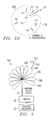
- FIG. 3is a digramatic representation of an antenna beam pattern for locating an interferer and forming a null in the direction of the interferer;
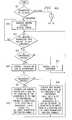
- FIG. 4Ais a flow chart of the present method for point-to-multipoint RF data transmission interference mitigation using adaptive beam pattern antennas, for transmissions.
- FIG. 4Bis a flow chart of the preset method for use with reception.
- FIG. 1Athere is shown antenna base station or hub antenna 10 with a plurality of subscriber stations S 1 through S 5 , all in direct communication with hub antenna 10 .
- the subscriber units S 1 through S 5generally use directional antennas directed at the hub to communicate with central hub antenna 10 .
- FIG. 1Ashows a system that is not experiencing any interference.
- the antenna pattern 11 Ais generally circular, because there is no need to distort the pattern. This pattern or cell 11 A is initially designed to give maximum communication coverage to the subscribers that are currently in communication with antenna 10 .
- the hub antennais comprised of several sectorized antennas, by way of example, 60 degrees wide. Six such sectorized antennas are used to create omnidirectional coverage. A conventional omnidirectional antenna would not be utilized, due to an inability to take full advantage of available frequencies through a frequency reuse plan. Nonetheless, coverage by the sectorized antennas would be uniform, assuming flat earth and terrain.
- the coverageis provided by channel A.
- a channel in the present RF data transmission systemis a frequency with an associated polarization. The same channel might not be used to cover 360 degrees. For example, each of the sectors of the sectorized antennas could have a particular channel, frequency and/or polarization.
- Points 13 and 14are the end points of point-to-point link 12 .
- Link 12is using the same frequency used in the sector which contains subscriber S 2 . If the interfering link 12 was not present, it would not be necessary to change frequency. However, the frequency in use by adjacent cells or sectors might dictate use of the present frequency.
- the RF data transmission systemis using unlicensed bands, there can be another point-to-point system with an interfering signal 12 , which is using the same, or an interfering, frequency or channel. If communication between hub antenna 10 and subscriber S 2 on the same frequency as the rest of the subscribers was desired, it would be necessary to switch all of the subscribers S 1 -S 5 to a different frequency.
- FIG. 1Bthere is constructed a radiation pattern 11 B, which creates a null in the direction of signal 12 .
- Pattern 11 Buses the same channel, A as shown in FIG. 1A, with the same frequency and same polarizations. Therefore, all of the subscribers, except for subscriber S 2 , would continue to communicate on the same frequency and same polarization as previously shown in FIG. 1 A. Thereby, the frequency plan throughout the system can be maintained. If an interfering point-to-point link 12 is established after the cells are deployed, it is compensated for through the use of a smart antenna changing the beam pattern. Generally, such interfering links will not cover a large portion of a cell.
- FIG. 2Ashows a uniform interference free antenna pattern similar to FIG. 1 A.
- a high power periodic interferer 21sends a signal 20 into the radiation pattern 20 A.
- the uniform radiation pattern 20 Ashown in FIG. 2A, will be sufficient during times when interfering source 20 is not present.
- radiation pattern 20 Bcan be generated. Thereby, communication is maintained with the other users in the cell, such as S 1 and S 3 -S 5 during the time of interference. When the interference is removed the cell reverts back to antenna pattern 20 A, serving all the users, including user S 2 .
- the interfering sourcescan be identified using omnidirectional antennas or through directional antennas.
- the disadvantage of using an omnidirectional antennais that the exact location of the source is difficult to ascertain.
- the location and/or direction of the interfering sourceneeds to be known.
- the location of the sourcecan be found using multiple narrow beam antennas. For example, if the cell is divided up into 36 sectors, each sector using a 10 degree antenna, then the location of the interfering source can be narrowed down to a 10 degree arc.
- FIG. 3shows one implementation where multiple narrow beams, such as beams 30 A-E, are used to cover a cell site. These antenna beams may be used only to identify the location of an interferer, or also for communication.
- interfering source 301generating interfering signal 302 is found on beam 30 D.
- Connection 31extends between the antennas generating beams 30 A-E and switch 32 .
- the switch 32is in turn connected to scanning receiver 33 .
- the scanning receiver 33is capable of scanning all of the frequencies in the band of interest. Alternatively, multiple scanning receivers 33 , for example, one per beam will allow elimination of switch 32 . Multiple scanning receivers might be necessary in order to identify pulses that have a very short duration. Scanning receivers 33 activates switch 32 in response to identification of an interference source, controlling input to the antennas. Using the scanning receiver, switch and antenna system the direction of the interference can be determined, which facilitates creating the radiation pattern shown in FIGS. 1B and 2B.
- the present method of an adaptive antenna patterncan be used in a frequency duplex system where transmission and reception are taking place on different frequencies.
- different patternscan be generated for transmission and reception.
- point-to-point link 12may only disrupt hub reception from users, but transmission to those users might not be impaired.
- these patternsare easily generated with a TDD system where the same frequency is used for both transmission and reception but at different times. In this case, if the interference is periodic or comes at a known time, the scheduling of the transmission can take place around occurrences of the interference.
- FIG. 4Athe method for practicing the present invention when transmitting is illustrated.
- a general uniform coverage antenna patternis generated at box 402 .
- the transmission rate available to each subscriberis monitored at box 403 . If the transmission rate is optimal then the uniform coverage antenna pattern is maintained. However, if this rate is not optimal a determination is made at 404 whether interference is present. If interference is not present then the gain to the subscriber is increased at box 405 and a determination of the available transmission rate is again made at 403 . If at 404 it is determined that interference is present, the location or direction of the interference and its type are determined at box 406 . Then at 407 a determination is made as to whether the interference is periodic.
- a new antenna patternis generated with a null in the direction of the interference, box 408 .
- Users in the direction of the interferenceare served using a alternative frequency and/or polarization, box 408 .
- the effected subscriberscan be directed to use a different hub, box 408 . All other transmissions to subscribers outside the null proceed normally, box 408 .
- a determination is made at box 407 that the interference is periodica new antenna pattern with a null in the direction of the interference, coinciding with the occurrence of the interference is created, box 409 . Transmissions to subscribers in the direction of the interference are made during clear times when the interference is not present and all other transmissions proceed normally, box 409 . Then the maximum transmission rate available to each subscriber is again evaluated at 403 and the process, steps 404 through 409 repeated.
- a general uniform coverage antenna patternis generated at box 410 .
- the transmission rate available from each subscriberis monitored at box 411 . If the transmission rate is optimal then the uniform coverage antenna pattern is maintained. However, if this rate is not optimal a determination is made at 412 whether interference is present. If interference is not present then the gain from the subscriber is increased at box 413 and a determination of the available transmission rate is again made at 411 . If at 412 it is determined that interference is present, the location or direction of the interference and its type are determined at box 414 . Then a determination is made as to whether the interference is periodic, at 415 .
- a new antenna patternis generated with a null in the direction of the interference.
- Users in the direction of the interferenceare served using a alternative frequency and/or polarization, box 416 .
- the effected subscriberscan be directed to use a different hub, box 416 . All other transmissions to subscribers outside the null proceed normally, box 416 .
- a new antenna pattern with a null in the direction of the interference, coinciding with the occurrence of the interferenceis created, box 417 . Transmissions to subscribers in the direction of the interference are made during clear times when the interference is not present, box 417 . All other transmissions proceed normally, box 417 . Then the maximum transmission rate available from each subscriber is again evaluated at 411 and steps 412 through 417 of the process are repeated.
Landscapes
- Engineering & Computer Science (AREA)
- Computer Networks & Wireless Communication (AREA)
- Signal Processing (AREA)
- Mobile Radio Communication Systems (AREA)
Abstract
Description
Claims (22)
Priority Applications (1)
| Application Number | Priority Date | Filing Date | Title |
|---|---|---|---|
| US09/853,046US6621454B1 (en) | 2001-05-10 | 2001-05-10 | Adaptive beam pattern antennas system and method for interference mitigation in point to multipoint RF data transmissions |
Applications Claiming Priority (1)
| Application Number | Priority Date | Filing Date | Title |
|---|---|---|---|
| US09/853,046US6621454B1 (en) | 2001-05-10 | 2001-05-10 | Adaptive beam pattern antennas system and method for interference mitigation in point to multipoint RF data transmissions |
Publications (1)
| Publication Number | Publication Date |
|---|---|
| US6621454B1true US6621454B1 (en) | 2003-09-16 |
Family
ID=27805641
Family Applications (1)
| Application Number | Title | Priority Date | Filing Date |
|---|---|---|---|
| US09/853,046Expired - LifetimeUS6621454B1 (en) | 2001-05-10 | 2001-05-10 | Adaptive beam pattern antennas system and method for interference mitigation in point to multipoint RF data transmissions |
Country Status (1)
| Country | Link |
|---|---|
| US (1) | US6621454B1 (en) |
Cited By (50)
| Publication number | Priority date | Publication date | Assignee | Title |
|---|---|---|---|---|
| US20030060206A1 (en)* | 2001-09-27 | 2003-03-27 | Erkka Sointula | Method and apparatus for avoiding mutual interference when co-locating mobile station and bluetooth systems |
| US20040102198A1 (en)* | 2002-11-27 | 2004-05-27 | Diener Neil R. | System and method for locating sources of unknown wireless radio signals |
| US20040218562A1 (en)* | 2003-03-07 | 2004-11-04 | Nokia Corporation | Channel selection in wireless telecommunication system |
| US20050003828A1 (en)* | 2002-04-09 | 2005-01-06 | Sugar Gary L. | System and method for locating wireless devices in an unsynchronized wireless environment |
| US20050221861A1 (en)* | 2004-03-31 | 2005-10-06 | Interdigital Technology Corporation | Mitigation of wireless transmit/receive unit (WTRU) to WTRU interference using multiple antennas or beams |
| US20050227748A1 (en)* | 2004-04-13 | 2005-10-13 | Airgain, Inc. | Direction-agile antenna controller |
| US20060292991A1 (en)* | 2000-11-10 | 2006-12-28 | Abramov Oleg Y | Dynamically optimized smart antenna system |
| US20070270100A1 (en)* | 2005-10-27 | 2007-11-22 | Avneesh Agrawal | Method and apparatus for estimating reverse link loading in a wireless communication system |
| US20070281621A1 (en)* | 2006-06-02 | 2007-12-06 | Stmicroelectronics N.V. | Method for managing eventual interferences during an information exchange between two wireless devices belonging for example to a multi-carriers based uwb communication system, and corresponding device |
| US20080069063A1 (en)* | 2006-09-15 | 2008-03-20 | Qualcomm Incorporated | Methods and apparatus related to multi-mode wireless communications device supporting both wide area network signaling and peer to peer signaling |
| US20080075059A1 (en)* | 2006-09-18 | 2008-03-27 | Nokia Corporation | Method and apparatus for reducing the guard band between wireless communication systems operating in the same geographical area |
| US20080117849A1 (en)* | 2006-09-08 | 2008-05-22 | Qualcomm Incorporated | Method and apparatus for interaction of fast other sector interference (osi) with slow osi |
| US20090023466A1 (en)* | 2004-06-18 | 2009-01-22 | Qualcomm Incorporated | Power control for a wireless communication system utilizing orthogonal multiplexing |
| US20100208712A1 (en)* | 2009-02-17 | 2010-08-19 | Wavion Ltd. | Enhancing WLAN performance in the presence of interference |
| US20110009105A1 (en)* | 2009-07-13 | 2011-01-13 | Jungwoo Lee | Self-organizing networks using directional beam antennas |
| US20110013612A1 (en)* | 2008-03-12 | 2011-01-20 | Cambridge Silicon Radio Limited | Protocol Coexistence |
| US20120002536A1 (en)* | 2001-12-20 | 2012-01-05 | Bellur Barghav R | Interference mitigation and adaptive routing in wireless ad-hoc packet-switched networks |
| US20120032833A1 (en)* | 2010-08-09 | 2012-02-09 | Milligan Stephen D | Radar coherent processing interval scheduling via ad hoc network |
| GB2491832A (en)* | 2011-06-13 | 2012-12-19 | Neul Ltd | Antenna nulling |
| WO2012171867A1 (en)* | 2011-06-13 | 2012-12-20 | Neul Ltd | Interference mitigation |
| US8442572B2 (en) | 2006-09-08 | 2013-05-14 | Qualcomm Incorporated | Method and apparatus for adjustments for delta-based power control in wireless communication systems |
| US20130122947A1 (en)* | 2006-09-15 | 2013-05-16 | Qualcomm Incorporated | Methods and apparatus related to power control and/or interference management in a mixed wireless communications system |
| US8488487B2 (en) | 2006-09-08 | 2013-07-16 | Qualcomm Incorporated | Method and apparatus for fast other sector interference (OSI) adjustment |
| US8516314B2 (en) | 2004-06-18 | 2013-08-20 | Qualcomm Incorporated | Robust erasure detection and erasure-rate-based closed loop power control |
| US8849210B2 (en) | 2005-03-15 | 2014-09-30 | Qualcomm Incorporated | Interference control in a wireless communication system |
| US8879425B2 (en) | 2005-03-15 | 2014-11-04 | Qualcomm Incorporated | Interference control in a wireless communication system |
| US8890744B1 (en) | 1999-04-07 | 2014-11-18 | James L. Geer | Method and apparatus for the detection of objects using electromagnetic wave attenuation patterns |
| US8929281B2 (en) | 2006-09-15 | 2015-01-06 | Qualcomm Incorporated | Methods and apparatus related to peer to peer device |
| GB2539732A (en)* | 2015-06-25 | 2016-12-28 | Airspan Networks Inc | A configurable antenna and method of operating such a configurable antenna |
| US9706419B2 (en) | 2015-06-25 | 2017-07-11 | Airspan Networks Inc. | Antenna apparatus and method of performing spatial nulling within the antenna apparatus |
| US9924385B2 (en) | 2015-06-25 | 2018-03-20 | Airspan Networks Inc. | Antenna apparatus and method of configuring a transmission beam for the antenna apparatus |
| US9973943B2 (en) | 2015-06-25 | 2018-05-15 | Airspan Networks Inc. | Wireless network configuration using path loss determination between nodes |
| US10070325B2 (en) | 2015-06-25 | 2018-09-04 | Airspan Networks Inc. | Sub-sampling antenna elements |
| US20190053247A1 (en)* | 2013-03-15 | 2019-02-14 | Isco International, Llc | Method and apparatus for interference mitigation utilizing antenna pattern adjustments |
| US10231139B2 (en) | 2015-06-25 | 2019-03-12 | Airspan Networks Inc. | Node role assignment in networks |
| US10257733B2 (en) | 2015-06-25 | 2019-04-09 | Airspan Networks Inc. | Managing external interference in a wireless network |
| US10306485B2 (en) | 2015-06-25 | 2019-05-28 | Airspan Networks Inc. | Configurable antenna and method of operating such a configurable antenna |
| US10425903B2 (en) | 2014-05-05 | 2019-09-24 | Isco International, Llc | Method and apparatus for mitigating interference |
| US10582434B2 (en) | 2011-06-13 | 2020-03-03 | Huawei Technologies Co., Ltd. | Device and method for deriving alignment information |
| US10652835B2 (en) | 2016-06-01 | 2020-05-12 | Isco International, Llc | Signal conditioning to mitigate interference impacting wireless communication links in radio access networks |
| US10667145B2 (en) | 2015-06-25 | 2020-05-26 | Airspan Networks Inc. | Bearing calculation |
| US10687284B2 (en) | 2014-05-05 | 2020-06-16 | Isco International, Llc | Method and apparatus for increasing performance of communication paths for communication nodes |
| US10834614B2 (en) | 2015-06-25 | 2020-11-10 | Airspan Networks Inc. | Quality of service in wireless backhauls |
| US10833783B2 (en) | 2017-08-09 | 2020-11-10 | Isco International, Llc | Method and apparatus for monitoring, detecting, testing, diagnosing and/or mitigating interference in a communication system |
| US10838040B2 (en) | 2015-11-13 | 2020-11-17 | FLIR Belgium BVBA | Detection and ranging systems and methods |
| US10879945B2 (en) | 2017-04-05 | 2020-12-29 | Isco International, Llc | Methods, systems and devices to improve channel utilization |
| US11166184B2 (en)* | 2018-06-29 | 2021-11-02 | Qualcomm Incorporated | Techniques to reduce base station to base station interference in semi-synchronous time division duplex operations |
| US11362693B2 (en) | 2017-08-09 | 2022-06-14 | Isco International, Llc | Method and apparatus for detecting and analyzing passive intermodulation interference in a communication system |
| US20230049027A1 (en)* | 2021-08-12 | 2023-02-16 | Nxp B.V. | Wireless device |
| US12445972B2 (en) | 2022-02-02 | 2025-10-14 | Isco International, Llc | Method and apparatus for performing signal conditioning to mitigate interference detected in a communication system |
Citations (2)
| Publication number | Priority date | Publication date | Assignee | Title |
|---|---|---|---|---|
| US5563610A (en) | 1995-06-08 | 1996-10-08 | Metawave Communications Corporation | Narrow beam antenna systems with angular diversity |
| US5805977A (en)* | 1996-04-01 | 1998-09-08 | Motorola, Inc. | Method and apparatus for controlling transmissions in a two-way selective call communication system |
- 2001
- 2001-05-10USUS09/853,046patent/US6621454B1/ennot_activeExpired - Lifetime
Patent Citations (2)
| Publication number | Priority date | Publication date | Assignee | Title |
|---|---|---|---|---|
| US5563610A (en) | 1995-06-08 | 1996-10-08 | Metawave Communications Corporation | Narrow beam antenna systems with angular diversity |
| US5805977A (en)* | 1996-04-01 | 1998-09-08 | Motorola, Inc. | Method and apparatus for controlling transmissions in a two-way selective call communication system |
Cited By (138)
| Publication number | Priority date | Publication date | Assignee | Title |
|---|---|---|---|---|
| US8890744B1 (en) | 1999-04-07 | 2014-11-18 | James L. Geer | Method and apparatus for the detection of objects using electromagnetic wave attenuation patterns |
| US20060292991A1 (en)* | 2000-11-10 | 2006-12-28 | Abramov Oleg Y | Dynamically optimized smart antenna system |
| US7627300B2 (en) | 2000-11-10 | 2009-12-01 | Airgain, Inc. | Dynamically optimized smart antenna system |
| US7162273B1 (en)* | 2000-11-10 | 2007-01-09 | Airgain, Inc. | Dynamically optimized smart antenna system |
| US20030060206A1 (en)* | 2001-09-27 | 2003-03-27 | Erkka Sointula | Method and apparatus for avoiding mutual interference when co-locating mobile station and bluetooth systems |
| US20120002536A1 (en)* | 2001-12-20 | 2012-01-05 | Bellur Barghav R | Interference mitigation and adaptive routing in wireless ad-hoc packet-switched networks |
| US20050003828A1 (en)* | 2002-04-09 | 2005-01-06 | Sugar Gary L. | System and method for locating wireless devices in an unsynchronized wireless environment |
| US7006838B2 (en) | 2002-11-27 | 2006-02-28 | Cognio, Inc. | System and method for locating sources of unknown wireless radio signals |
| US20040102198A1 (en)* | 2002-11-27 | 2004-05-27 | Diener Neil R. | System and method for locating sources of unknown wireless radio signals |
| US7720029B2 (en)* | 2003-03-07 | 2010-05-18 | Nokia Corporation | Channel selection in wireless telecommunication system |
| US20040218562A1 (en)* | 2003-03-07 | 2004-11-04 | Nokia Corporation | Channel selection in wireless telecommunication system |
| US20050221861A1 (en)* | 2004-03-31 | 2005-10-06 | Interdigital Technology Corporation | Mitigation of wireless transmit/receive unit (WTRU) to WTRU interference using multiple antennas or beams |
| US7835700B2 (en) | 2004-03-31 | 2010-11-16 | Interdigital Technology Corporation | Mitigation of wireless transmit/receive unit (WTRU) to WTRU interference using multiple antennas or beams |
| US20100081396A1 (en)* | 2004-03-31 | 2010-04-01 | Interdigital Technology Corporation | Mitigation of wireless transmit/receive unit (wtru) to wtru interference using multiple antennas or beams |
| US7630688B2 (en) | 2004-03-31 | 2009-12-08 | Interdigital Technology Corporation | Mitigation of wireless transmit/receive unit (WTRU) to WTRU interference using multiple antennas or beams |
| EP1738564A4 (en)* | 2004-03-31 | 2009-05-06 | Interdigital Tech Corp | ELIMINATION OF INTERFERENCE BETWEEN WIRELESS TRANSMISSION / RECEIVING UNITS (WTRU) USING MULTIPLE ANTENNAS OR RADIATION |
| US20050227748A1 (en)* | 2004-04-13 | 2005-10-13 | Airgain, Inc. | Direction-agile antenna controller |
| US8478202B2 (en) | 2004-06-18 | 2013-07-02 | Qualcomm Incorporated | Power control for a wireless communication system utilizing orthogonal multiplexing |
| US20090023466A1 (en)* | 2004-06-18 | 2009-01-22 | Qualcomm Incorporated | Power control for a wireless communication system utilizing orthogonal multiplexing |
| US8543152B2 (en) | 2004-06-18 | 2013-09-24 | Qualcomm Incorporated | Power control for a wireless communication system utilizing orthogonal multiplexing |
| US8452316B2 (en) | 2004-06-18 | 2013-05-28 | Qualcomm Incorporated | Power control for a wireless communication system utilizing orthogonal multiplexing |
| US8516314B2 (en) | 2004-06-18 | 2013-08-20 | Qualcomm Incorporated | Robust erasure detection and erasure-rate-based closed loop power control |
| US8879425B2 (en) | 2005-03-15 | 2014-11-04 | Qualcomm Incorporated | Interference control in a wireless communication system |
| US8942639B2 (en) | 2005-03-15 | 2015-01-27 | Qualcomm Incorporated | Interference control in a wireless communication system |
| US8849210B2 (en) | 2005-03-15 | 2014-09-30 | Qualcomm Incorporated | Interference control in a wireless communication system |
| US20070270100A1 (en)* | 2005-10-27 | 2007-11-22 | Avneesh Agrawal | Method and apparatus for estimating reverse link loading in a wireless communication system |
| US8929908B2 (en)* | 2005-10-27 | 2015-01-06 | Qualcomm Incorporated | Method and apparatus for estimating reverse link loading in a wireless communication system |
| US20070281621A1 (en)* | 2006-06-02 | 2007-12-06 | Stmicroelectronics N.V. | Method for managing eventual interferences during an information exchange between two wireless devices belonging for example to a multi-carriers based uwb communication system, and corresponding device |
| US8498577B2 (en)* | 2006-06-02 | 2013-07-30 | Stmicroelectronics N.V. | Method for managing eventual interferences during an information exchange between two wireless devices belonging for example to a multi-carriers based UWB communication system, and corresponding device |
| US20080117849A1 (en)* | 2006-09-08 | 2008-05-22 | Qualcomm Incorporated | Method and apparatus for interaction of fast other sector interference (osi) with slow osi |
| US8670777B2 (en) | 2006-09-08 | 2014-03-11 | Qualcomm Incorporated | Method and apparatus for fast other sector interference (OSI) adjustment |
| US8442572B2 (en) | 2006-09-08 | 2013-05-14 | Qualcomm Incorporated | Method and apparatus for adjustments for delta-based power control in wireless communication systems |
| US8488487B2 (en) | 2006-09-08 | 2013-07-16 | Qualcomm Incorporated | Method and apparatus for fast other sector interference (OSI) adjustment |
| US9119163B2 (en)* | 2006-09-15 | 2015-08-25 | Qualcomm Incorporated | Methods and apparatus related to power control and/or interference management in a mixed wireless communications system |
| US20080069063A1 (en)* | 2006-09-15 | 2008-03-20 | Qualcomm Incorporated | Methods and apparatus related to multi-mode wireless communications device supporting both wide area network signaling and peer to peer signaling |
| US20130122947A1 (en)* | 2006-09-15 | 2013-05-16 | Qualcomm Incorporated | Methods and apparatus related to power control and/or interference management in a mixed wireless communications system |
| US8634869B2 (en) | 2006-09-15 | 2014-01-21 | Qualcomm Incorporated | Methods and apparatus related to multi-mode wireless communications device supporting both wide area network signaling and peer to peer signaling |
| US8929281B2 (en) | 2006-09-15 | 2015-01-06 | Qualcomm Incorporated | Methods and apparatus related to peer to peer device |
| US20080075059A1 (en)* | 2006-09-18 | 2008-03-27 | Nokia Corporation | Method and apparatus for reducing the guard band between wireless communication systems operating in the same geographical area |
| WO2008035287A3 (en)* | 2006-09-18 | 2008-08-14 | Nokia Corp | Method and apparatus for reducing the guard band between wireless communication systems operating in the same geographical area |
| US8554146B2 (en)* | 2006-09-18 | 2013-10-08 | Nokia Corporation | Method and apparatus for reducing the guard band between wireless communication systems operating in the same geographical area |
| US20110013612A1 (en)* | 2008-03-12 | 2011-01-20 | Cambridge Silicon Radio Limited | Protocol Coexistence |
| US8295258B2 (en) | 2009-02-17 | 2012-10-23 | Wavion, Ltd | Enhancing WLAN performance in the presence of interference |
| US20100208712A1 (en)* | 2009-02-17 | 2010-08-19 | Wavion Ltd. | Enhancing WLAN performance in the presence of interference |
| US20110009105A1 (en)* | 2009-07-13 | 2011-01-13 | Jungwoo Lee | Self-organizing networks using directional beam antennas |
| US20120032833A1 (en)* | 2010-08-09 | 2012-02-09 | Milligan Stephen D | Radar coherent processing interval scheduling via ad hoc network |
| US8730088B2 (en)* | 2010-08-09 | 2014-05-20 | Raytheon Bbn Technologies Corp. | Radar coherent processing interval scheduling via ad hoc network |
| US20140321509A1 (en)* | 2011-06-13 | 2014-10-30 | Neul Ltd. | Interference mitigation |
| GB2491832A (en)* | 2011-06-13 | 2012-12-19 | Neul Ltd | Antenna nulling |
| WO2012171867A1 (en)* | 2011-06-13 | 2012-12-20 | Neul Ltd | Interference mitigation |
| GB2492052B (en)* | 2011-06-13 | 2015-06-24 | Neul Ltd | Interference mitigation |
| WO2012171710A1 (en)* | 2011-06-13 | 2012-12-20 | Neul Ltd | Antenna nulling |
| US10582434B2 (en) | 2011-06-13 | 2020-03-03 | Huawei Technologies Co., Ltd. | Device and method for deriving alignment information |
| US9774366B2 (en)* | 2011-06-13 | 2017-09-26 | Huawei Technologies Co., Ltd. | Interference mitigation |
| US10560952B2 (en) | 2013-03-15 | 2020-02-11 | Isco International, Llc | Creating library of interferers |
| US10841928B2 (en) | 2013-03-15 | 2020-11-17 | Isco International, Llc | Method and apparatus for signal interference processing |
| US12317304B2 (en) | 2013-03-15 | 2025-05-27 | Isco International, Llc | Method and apparatus for collecting and processing interference information |
| US12219588B2 (en) | 2013-03-15 | 2025-02-04 | Isco International, Llc | Method and apparatus for interference mitigation utilizing antenna pattern adjustments |
| US12022502B2 (en) | 2013-03-15 | 2024-06-25 | Isco International, Llc | Creating library of interferers |
| US20190053247A1 (en)* | 2013-03-15 | 2019-02-14 | Isco International, Llc | Method and apparatus for interference mitigation utilizing antenna pattern adjustments |
| US11950270B2 (en) | 2013-03-15 | 2024-04-02 | Isco International, Llc | Method and apparatus for collecting and processing interference information |
| US11711839B2 (en) | 2013-03-15 | 2023-07-25 | Isco International, Llc | Method and apparatus for avoiding interference |
| US11653374B2 (en) | 2013-03-15 | 2023-05-16 | Isco International, Llc | Method and apparatus for signal interference processing |
| US10419195B2 (en) | 2013-03-15 | 2019-09-17 | Isco International, Llc | Creating library of interferers |
| US10420114B2 (en) | 2013-03-15 | 2019-09-17 | Isco International, Llc | Method and apparatus for signal interference processing |
| US11638268B2 (en) | 2013-03-15 | 2023-04-25 | Isco International, Llc | Method and apparatus for interference mitigation utilizing antenna pattern adjustments |
| US11582763B2 (en) | 2013-03-15 | 2023-02-14 | Isco International, Llc | Creating library of interferers |
| US11445517B2 (en) | 2013-03-15 | 2022-09-13 | Isco International, Llc | Method and apparatus for signal interference processing |
| US10517101B2 (en) | 2013-03-15 | 2019-12-24 | Isco International, Llc | Method and apparatus for mitigating signal interference in a feedback system |
| US11375516B2 (en) | 2013-03-15 | 2022-06-28 | Isco International, Llc | Method and apparatus for signal interference avoidance |
| US11304204B2 (en) | 2013-03-15 | 2022-04-12 | Isco International, Llc | Method and apparatus for signal interference processing |
| US10582511B2 (en) | 2013-03-15 | 2020-03-03 | Isco International, Llc | Method and apparatus for signal interference processing |
| US10582510B2 (en) | 2013-03-15 | 2020-03-03 | Isco International, Llc | Method and apparatus for avoiding interference |
| US11191086B2 (en) | 2013-03-15 | 2021-11-30 | Isco International, Llc | Method and apparatus for mitigating signal interference in a feedback system |
| US11166288B2 (en) | 2013-03-15 | 2021-11-02 | Isco International, Llc | Method and apparatus for collecting and processing interference information |
| US10652901B2 (en) | 2013-03-15 | 2020-05-12 | Isco International, Llc | Method and apparatus for signal interference processing |
| US10652903B2 (en)* | 2013-03-15 | 2020-05-12 | Isco International, Llc | Method and apparatus for interference mitigation utilizing antenna pattern adjustments |
| US11134502B2 (en)* | 2013-03-15 | 2021-09-28 | Isco International, Llc | Method and apparatus for interference mitigation utilizing antenna pattern adjustments |
| US11115988B2 (en) | 2013-03-15 | 2021-09-07 | Isco International, Llc | Method and apparatus for avoiding interference |
| US10667275B2 (en) | 2013-03-15 | 2020-05-26 | Isco International, Llc | Method and apparatus for signal interference avoidance |
| US10945271B2 (en) | 2013-03-15 | 2021-03-09 | Isco International, Llc | Creating library of interferers |
| US10798718B2 (en) | 2013-03-15 | 2020-10-06 | Isco International, Llc | Method and apparatus for collecting and processing interference information |
| US10805937B2 (en) | 2013-03-15 | 2020-10-13 | Isco International, Llc | Method and apparatus for avoiding interference |
| US10904890B2 (en) | 2013-03-15 | 2021-01-26 | Isco International, Llc | Method and apparatus for signal interference processing |
| US10880902B2 (en) | 2013-03-15 | 2020-12-29 | Isco International, Llc | Method and apparatus for signal interference processing |
| US10880901B2 (en) | 2013-03-15 | 2020-12-29 | Isco International, Llc | Method and apparatus for mitigating signal interference in a feedback system |
| US10959185B2 (en) | 2014-05-05 | 2021-03-23 | Isco International, Llc | Method and apparatus for increasing performance of communication links of cooperative communication nodes |
| US10575260B2 (en) | 2014-05-05 | 2020-02-25 | Isco International, Llc | Method and apparatus for increasing performance of communication links of cooperative communication nodes |
| US10834684B2 (en) | 2014-05-05 | 2020-11-10 | Isco International, Llc | Adjusting signal power to increase performance of communication links of communication nodes |
| US10506526B2 (en) | 2014-05-05 | 2019-12-10 | Isco International, Llc | Method and apparatus for increasing performance of a communication link of a communication node |
| US11570719B2 (en) | 2014-05-05 | 2023-01-31 | Isco International, Llc | Method and apparatus for increasing performance of communication links of cooperative communication nodes |
| US12225475B2 (en) | 2014-05-05 | 2025-02-11 | Isco International, Llc | Method and apparatus for increasing performance of communication links of cooperative communication nodes |
| US10512044B2 (en) | 2014-05-05 | 2019-12-17 | Isco International, Llc | Method and apparatus for increasing performance of communication links of communication nodes |
| US10820282B2 (en) | 2014-05-05 | 2020-10-27 | Isco International, Llc | Method and apparatus for increasing performance of a communication link of a communication node |
| US10687284B2 (en) | 2014-05-05 | 2020-06-16 | Isco International, Llc | Method and apparatus for increasing performance of communication paths for communication nodes |
| US11412457B2 (en) | 2014-05-05 | 2022-08-09 | Isco International, Llc | Adjusting signal power to increase performance of communication links of communication nodes |
| US11330531B2 (en) | 2014-05-05 | 2022-05-10 | Isco International, Llc | Method and apparatus for increasing performance of communication links of communication nodes |
| US10425903B2 (en) | 2014-05-05 | 2019-09-24 | Isco International, Llc | Method and apparatus for mitigating interference |
| US10834683B2 (en) | 2014-05-05 | 2020-11-10 | Isco International, Llc | Method and apparatus for increasing performance of communication links of communication nodes |
| US11197247B2 (en) | 2014-05-05 | 2021-12-07 | Isco International, Llc | Method and apparatus for increasing performance of communication paths for communication nodes |
| US11877247B2 (en) | 2014-05-05 | 2024-01-16 | Isco International, Llc | Method and apparatus for increasing performance of communication links of cooperative communication nodes |
| US10609651B2 (en) | 2014-05-05 | 2020-03-31 | Isco International, Llc | Adjusting signal power to increase performance of communication links of communication nodes |
| US11811127B2 (en) | 2015-06-25 | 2023-11-07 | Airspan Ip Holdco Llc | Wireless network controller and method of controlling a wireless network |
| US9706419B2 (en) | 2015-06-25 | 2017-07-11 | Airspan Networks Inc. | Antenna apparatus and method of performing spatial nulling within the antenna apparatus |
| US10667145B2 (en) | 2015-06-25 | 2020-05-26 | Airspan Networks Inc. | Bearing calculation |
| GB2539732A (en)* | 2015-06-25 | 2016-12-28 | Airspan Networks Inc | A configurable antenna and method of operating such a configurable antenna |
| US10098018B2 (en) | 2015-06-25 | 2018-10-09 | Airspan Networks Inc. | Configurable antenna and method of operating such a configurable antenna |
| US9973943B2 (en) | 2015-06-25 | 2018-05-15 | Airspan Networks Inc. | Wireless network configuration using path loss determination between nodes |
| US10306485B2 (en) | 2015-06-25 | 2019-05-28 | Airspan Networks Inc. | Configurable antenna and method of operating such a configurable antenna |
| US10070325B2 (en) | 2015-06-25 | 2018-09-04 | Airspan Networks Inc. | Sub-sampling antenna elements |
| US10231139B2 (en) | 2015-06-25 | 2019-03-12 | Airspan Networks Inc. | Node role assignment in networks |
| US9924385B2 (en) | 2015-06-25 | 2018-03-20 | Airspan Networks Inc. | Antenna apparatus and method of configuring a transmission beam for the antenna apparatus |
| US10257733B2 (en) | 2015-06-25 | 2019-04-09 | Airspan Networks Inc. | Managing external interference in a wireless network |
| US10834614B2 (en) | 2015-06-25 | 2020-11-10 | Airspan Networks Inc. | Quality of service in wireless backhauls |
| US10838040B2 (en) | 2015-11-13 | 2020-11-17 | FLIR Belgium BVBA | Detection and ranging systems and methods |
| US10952155B2 (en) | 2016-06-01 | 2021-03-16 | Isco International, Llc | Method and apparatus for performing signal conditioning to mitigate interference detected in a communication system |
| US10652835B2 (en) | 2016-06-01 | 2020-05-12 | Isco International, Llc | Signal conditioning to mitigate interference impacting wireless communication links in radio access networks |
| US11277803B2 (en) | 2016-06-01 | 2022-03-15 | Isco International, Llc | Signal conditioning to mitigate interference |
| US10979093B2 (en) | 2017-04-05 | 2021-04-13 | Isco International, Llc | Method and apparatus for real-time monitoring and field adjustment |
| US11855670B2 (en) | 2017-04-05 | 2023-12-26 | Isco International, Llc | Method and apparatus for real-time monitoring and field adjustment |
| US10879945B2 (en) | 2017-04-05 | 2020-12-29 | Isco International, Llc | Methods, systems and devices to improve channel utilization |
| US11502711B2 (en) | 2017-04-05 | 2022-11-15 | Isco International, Llc | Methods, systems and devices to improve channel utilization |
| US10979092B2 (en) | 2017-04-05 | 2021-04-13 | Isco International, Llc | Method and apparatus for mitigating interference in CPRI uplink paths |
| US11456766B2 (en) | 2017-04-05 | 2022-09-27 | Isco International, Llc | Virtualized methods, systems and devices to mitigate channel interference |
| US11722164B2 (en) | 2017-04-05 | 2023-08-08 | Isco International, Llc | Correlating network and physical layer activities |
| US12166517B2 (en) | 2017-04-05 | 2024-12-10 | Isco International, Llc | Methods, systems and devices to improve channel utilization |
| US12149272B2 (en) | 2017-04-05 | 2024-11-19 | Isco International, Llc | Method and apparatus for real-time monitoring and field adjustment |
| US11601149B2 (en) | 2017-04-05 | 2023-03-07 | Isco International, Llc | Method and apparatus for real-time monitoring and field adjustment |
| US11075660B2 (en) | 2017-04-05 | 2021-07-27 | Isco International, Llc | Managing interference in control channels and methods thereof |
| US11184094B2 (en) | 2017-08-09 | 2021-11-23 | Isco International, Llc | Method and apparatus for monitoring, detecting, testing, diagnosing and/or mitigating interference in a communication system |
| US12101133B2 (en) | 2017-08-09 | 2024-09-24 | Isco International, Llc | Method and apparatus for monitoring, detecting, testing, diagnosing and/or mitigating interference in a communication system |
| US11362693B2 (en) | 2017-08-09 | 2022-06-14 | Isco International, Llc | Method and apparatus for detecting and analyzing passive intermodulation interference in a communication system |
| US11728912B2 (en) | 2017-08-09 | 2023-08-15 | Isco International, Llc | Method and apparatus for monitoring, detecting, testing, diagnosing and/or mitigating interference in a communication system |
| US10833783B2 (en) | 2017-08-09 | 2020-11-10 | Isco International, Llc | Method and apparatus for monitoring, detecting, testing, diagnosing and/or mitigating interference in a communication system |
| US11166184B2 (en)* | 2018-06-29 | 2021-11-02 | Qualcomm Incorporated | Techniques to reduce base station to base station interference in semi-synchronous time division duplex operations |
| US11671862B2 (en) | 2018-06-29 | 2023-06-06 | Qualcomm Incorporated | Techniques to reduce base station to base station interference in semi-synchronous time division duplex operations |
| US20230049027A1 (en)* | 2021-08-12 | 2023-02-16 | Nxp B.V. | Wireless device |
| US12445972B2 (en) | 2022-02-02 | 2025-10-14 | Isco International, Llc | Method and apparatus for performing signal conditioning to mitigate interference detected in a communication system |
Similar Documents
| Publication | Publication Date | Title |
|---|---|---|
| US6621454B1 (en) | Adaptive beam pattern antennas system and method for interference mitigation in point to multipoint RF data transmissions | |
| JP5160524B2 (en) | Distributed wireless architecture using microcast | |
| JP5306658B2 (en) | Simultaneous detection and data transmission | |
| AU700187B2 (en) | Method of allocating frequency bands to different cells, and TDMA cellular radio system | |
| US7835700B2 (en) | Mitigation of wireless transmit/receive unit (WTRU) to WTRU interference using multiple antennas or beams | |
| US7675840B1 (en) | System and method for mitigating data flow control problems in the presence of certain interference parameters | |
| US8311582B2 (en) | Asymmetrical beams for spectrum efficiency | |
| US7194269B2 (en) | Method and wireless communication hub for data communications | |
| US20020155811A1 (en) | System and method for adapting RF transmissions to mitigate the effects of certain interferences | |
| Guidotti et al. | Coexistence and mutual interference between mobile and broadcasting systems | |
| US6415131B1 (en) | DMA cellular radio system with a channel quality criterion | |
| Deslandes et al. | Analysis of interference issues in integrated satellite and terrestrial mobile systems | |
| US7263143B1 (en) | System and method for statistically directing automatic gain control | |
| Hoymann et al. | Dimensioning cellular multihop WiMAX networks | |
| Tang et al. | Frequency sharing between satellite and terrestrial systems in the Ka band: A database approach | |
| IL278206B1 (en) | Orbital Base Station Filtering of Interference from Terrestrial-Terrestrial Communications | |
| Shamsan et al. | Spectrum sharing studies of IMT-advanced and FWA services under different clutter loss and channel bandwidths effects | |
| US20090163138A1 (en) | Hybrid terrestrial-satellite telecommunications network with adaptable terrestrial relay-stations | |
| Guidotti et al. | Spectrum awareness and exploitation for cognitive radio satellite communications | |
| RU2161866C1 (en) | Jamproof radio communication system | |
| Icolari et al. | Beam pattern allocation strategies for satellite cognitive radio systems | |
| EP1176839A2 (en) | Hub with inclined beams for wireless networks | |
| Shamsan et al. | Simulation model for compatibility of co-sited IMT-advanced and point to multipoint services | |
| US20100291944A1 (en) | Cognitive network | |
| Heo et al. | Co-channel interference analysis of multi-beam satellite communication systems for mobile satellite service |
Legal Events
| Date | Code | Title | Description |
|---|---|---|---|
| AS | Assignment | Owner name:VECTRAD NETWORKS CORPORATION, WASHINGTON Free format text:ASSIGNMENT OF ASSIGNORS INTEREST;ASSIGNORS:REUDINK, MARK D.;ROTHAAR, BRUCE C.;PRISMANTAS, JERRY;REEL/FRAME:012022/0663 Effective date:20010531 | |
| STCF | Information on status: patent grant | Free format text:PATENTED CASE | |
| AS | Assignment | Owner name:ADAPTIX, INC., WASHINGTON Free format text:ASSIGNMENT OF ASSIGNORS INTEREST;ASSIGNOR:VECTRAD NETWORKS CORPORATION;REEL/FRAME:015841/0522 Effective date:20041217 | |
| AS | Assignment | Owner name:BAKER COMMUNICATIONS FUND II (QP), L.P.,NEW YORK Free format text:SECURITY AGREEMENT;ASSIGNOR:ADAPTIX, INC.;REEL/FRAME:018875/0448 Effective date:20070105 Owner name:BAKER COMMUNICATIONS FUND II, L.P.,NEW YORK Free format text:SECURITY AGREEMENT;ASSIGNOR:ADAPTIX, INC.;REEL/FRAME:018875/0448 Effective date:20070105 Owner name:BAKER COMMUNICATIONS FUND II, L.P., NEW YORK Free format text:SECURITY AGREEMENT;ASSIGNOR:ADAPTIX, INC.;REEL/FRAME:018875/0448 Effective date:20070105 Owner name:BAKER COMMUNICATIONS FUND II (QP), L.P., NEW YORK Free format text:SECURITY AGREEMENT;ASSIGNOR:ADAPTIX, INC.;REEL/FRAME:018875/0448 Effective date:20070105 | |
| FPAY | Fee payment | Year of fee payment:4 | |
| AS | Assignment | Owner name:ADAPTIX, INC., TEXAS Free format text:RELEASE BY SECURED PARTY;ASSIGNORS:BAKER COMMUNICATIONS FUND II (QP), L.P.;BAKER COMMUNICATIONS FUND II, L.P.;REEL/FRAME:024767/0952 Effective date:20100731 | |
| AS | Assignment | Owner name:NETGEAR, INC., CALIFORNIA Free format text:ASSIGNMENT OF ASSIGNORS INTEREST;ASSIGNOR:ADAPTIX, INC.;REEL/FRAME:024804/0961 Effective date:20100802 | |
| FEPP | Fee payment procedure | Free format text:PAT HOLDER NO LONGER CLAIMS SMALL ENTITY STATUS, ENTITY STATUS SET TO UNDISCOUNTED (ORIGINAL EVENT CODE: STOL); ENTITY STATUS OF PATENT OWNER: LARGE ENTITY | |
| FPAY | Fee payment | Year of fee payment:8 | |
| FEPP | Fee payment procedure | Free format text:PAYOR NUMBER ASSIGNED (ORIGINAL EVENT CODE: ASPN); ENTITY STATUS OF PATENT OWNER: LARGE ENTITY | |
| FPAY | Fee payment | Year of fee payment:12 |