US6620197B2 - Method and apparatus for performing a shoulder replacement procedure in the treatment of cuff tear arthropathy - Google Patents
Method and apparatus for performing a shoulder replacement procedure in the treatment of cuff tear arthropathyDownload PDFInfo
- Publication number
- US6620197B2 US6620197B2US09/767,473US76747301AUS6620197B2US 6620197 B2US6620197 B2US 6620197B2US 76747301 AUS76747301 AUS 76747301AUS 6620197 B2US6620197 B2US 6620197B2
- Authority
- US
- United States
- Prior art keywords
- patient
- bearing portion
- glenoid
- acromion
- humerus
- Prior art date
- Legal status (The legal status is an assumption and is not a legal conclusion. Google has not performed a legal analysis and makes no representation as to the accuracy of the status listed.)
- Expired - Lifetime
Links
Images


Classifications
- A—HUMAN NECESSITIES
- A61—MEDICAL OR VETERINARY SCIENCE; HYGIENE
- A61B—DIAGNOSIS; SURGERY; IDENTIFICATION
- A61B17/00—Surgical instruments, devices or methods
- A61B17/14—Surgical saws
- A61B17/15—Guides therefor
- A61B17/154—Guides therefor for preparing bone for knee prosthesis
- A—HUMAN NECESSITIES
- A61—MEDICAL OR VETERINARY SCIENCE; HYGIENE
- A61F—FILTERS IMPLANTABLE INTO BLOOD VESSELS; PROSTHESES; DEVICES PROVIDING PATENCY TO, OR PREVENTING COLLAPSING OF, TUBULAR STRUCTURES OF THE BODY, e.g. STENTS; ORTHOPAEDIC, NURSING OR CONTRACEPTIVE DEVICES; FOMENTATION; TREATMENT OR PROTECTION OF EYES OR EARS; BANDAGES, DRESSINGS OR ABSORBENT PADS; FIRST-AID KITS
- A61F2/00—Filters implantable into blood vessels; Prostheses, i.e. artificial substitutes or replacements for parts of the body; Appliances for connecting them with the body; Devices providing patency to, or preventing collapsing of, tubular structures of the body, e.g. stents
- A61F2/02—Prostheses implantable into the body
- A61F2/30—Joints
- A61F2/40—Joints for shoulders
- A—HUMAN NECESSITIES
- A61—MEDICAL OR VETERINARY SCIENCE; HYGIENE
- A61B—DIAGNOSIS; SURGERY; IDENTIFICATION
- A61B17/00—Surgical instruments, devices or methods
- A61B17/14—Surgical saws
- A61B17/15—Guides therefor
- A—HUMAN NECESSITIES
- A61—MEDICAL OR VETERINARY SCIENCE; HYGIENE
- A61B—DIAGNOSIS; SURGERY; IDENTIFICATION
- A61B17/00—Surgical instruments, devices or methods
- A61B17/16—Instruments for performing osteoclasis; Drills or chisels for bones; Trepans
- A61B17/164—Instruments for performing osteoclasis; Drills or chisels for bones; Trepans intramedullary
- A—HUMAN NECESSITIES
- A61—MEDICAL OR VETERINARY SCIENCE; HYGIENE
- A61B—DIAGNOSIS; SURGERY; IDENTIFICATION
- A61B17/00—Surgical instruments, devices or methods
- A61B17/16—Instruments for performing osteoclasis; Drills or chisels for bones; Trepans
- A61B17/1662—Instruments for performing osteoclasis; Drills or chisels for bones; Trepans for particular parts of the body
- A61B17/1684—Instruments for performing osteoclasis; Drills or chisels for bones; Trepans for particular parts of the body for the shoulder
- A—HUMAN NECESSITIES
- A61—MEDICAL OR VETERINARY SCIENCE; HYGIENE
- A61F—FILTERS IMPLANTABLE INTO BLOOD VESSELS; PROSTHESES; DEVICES PROVIDING PATENCY TO, OR PREVENTING COLLAPSING OF, TUBULAR STRUCTURES OF THE BODY, e.g. STENTS; ORTHOPAEDIC, NURSING OR CONTRACEPTIVE DEVICES; FOMENTATION; TREATMENT OR PROTECTION OF EYES OR EARS; BANDAGES, DRESSINGS OR ABSORBENT PADS; FIRST-AID KITS
- A61F2/00—Filters implantable into blood vessels; Prostheses, i.e. artificial substitutes or replacements for parts of the body; Appliances for connecting them with the body; Devices providing patency to, or preventing collapsing of, tubular structures of the body, e.g. stents
- A61F2/02—Prostheses implantable into the body
- A61F2/30—Joints
- A61F2/40—Joints for shoulders
- A61F2/4014—Humeral heads or necks; Connections of endoprosthetic heads or necks to endoprosthetic humeral shafts
- A—HUMAN NECESSITIES
- A61—MEDICAL OR VETERINARY SCIENCE; HYGIENE
- A61F—FILTERS IMPLANTABLE INTO BLOOD VESSELS; PROSTHESES; DEVICES PROVIDING PATENCY TO, OR PREVENTING COLLAPSING OF, TUBULAR STRUCTURES OF THE BODY, e.g. STENTS; ORTHOPAEDIC, NURSING OR CONTRACEPTIVE DEVICES; FOMENTATION; TREATMENT OR PROTECTION OF EYES OR EARS; BANDAGES, DRESSINGS OR ABSORBENT PADS; FIRST-AID KITS
- A61F2/00—Filters implantable into blood vessels; Prostheses, i.e. artificial substitutes or replacements for parts of the body; Appliances for connecting them with the body; Devices providing patency to, or preventing collapsing of, tubular structures of the body, e.g. stents
- A61F2/02—Prostheses implantable into the body
- A61F2/30—Joints
- A61F2/40—Joints for shoulders
- A61F2/4059—Humeral shafts
- A—HUMAN NECESSITIES
- A61—MEDICAL OR VETERINARY SCIENCE; HYGIENE
- A61F—FILTERS IMPLANTABLE INTO BLOOD VESSELS; PROSTHESES; DEVICES PROVIDING PATENCY TO, OR PREVENTING COLLAPSING OF, TUBULAR STRUCTURES OF THE BODY, e.g. STENTS; ORTHOPAEDIC, NURSING OR CONTRACEPTIVE DEVICES; FOMENTATION; TREATMENT OR PROTECTION OF EYES OR EARS; BANDAGES, DRESSINGS OR ABSORBENT PADS; FIRST-AID KITS
- A61F2/00—Filters implantable into blood vessels; Prostheses, i.e. artificial substitutes or replacements for parts of the body; Appliances for connecting them with the body; Devices providing patency to, or preventing collapsing of, tubular structures of the body, e.g. stents
- A61F2/02—Prostheses implantable into the body
- A61F2/30—Joints
- A61F2002/30001—Additional features of subject-matter classified in A61F2/28, A61F2/30 and subgroups thereof
- A61F2002/30316—The prosthesis having different structural features at different locations within the same prosthesis; Connections between prosthetic parts; Special structural features of bone or joint prostheses not otherwise provided for
- A61F2002/30329—Connections or couplings between prosthetic parts, e.g. between modular parts; Connecting elements
- A61F2002/30331—Connections or couplings between prosthetic parts, e.g. between modular parts; Connecting elements made by longitudinally pushing a protrusion into a complementarily-shaped recess, e.g. held by friction fit
- A61F2002/30332—Conically- or frustoconically-shaped protrusion and recess
- A—HUMAN NECESSITIES
- A61—MEDICAL OR VETERINARY SCIENCE; HYGIENE
- A61F—FILTERS IMPLANTABLE INTO BLOOD VESSELS; PROSTHESES; DEVICES PROVIDING PATENCY TO, OR PREVENTING COLLAPSING OF, TUBULAR STRUCTURES OF THE BODY, e.g. STENTS; ORTHOPAEDIC, NURSING OR CONTRACEPTIVE DEVICES; FOMENTATION; TREATMENT OR PROTECTION OF EYES OR EARS; BANDAGES, DRESSINGS OR ABSORBENT PADS; FIRST-AID KITS
- A61F2/00—Filters implantable into blood vessels; Prostheses, i.e. artificial substitutes or replacements for parts of the body; Appliances for connecting them with the body; Devices providing patency to, or preventing collapsing of, tubular structures of the body, e.g. stents
- A61F2/02—Prostheses implantable into the body
- A61F2/30—Joints
- A61F2002/30001—Additional features of subject-matter classified in A61F2/28, A61F2/30 and subgroups thereof
- A61F2002/30316—The prosthesis having different structural features at different locations within the same prosthesis; Connections between prosthetic parts; Special structural features of bone or joint prostheses not otherwise provided for
- A61F2002/30535—Special structural features of bone or joint prostheses not otherwise provided for
- A61F2002/30604—Special structural features of bone or joint prostheses not otherwise provided for modular
- A—HUMAN NECESSITIES
- A61—MEDICAL OR VETERINARY SCIENCE; HYGIENE
- A61F—FILTERS IMPLANTABLE INTO BLOOD VESSELS; PROSTHESES; DEVICES PROVIDING PATENCY TO, OR PREVENTING COLLAPSING OF, TUBULAR STRUCTURES OF THE BODY, e.g. STENTS; ORTHOPAEDIC, NURSING OR CONTRACEPTIVE DEVICES; FOMENTATION; TREATMENT OR PROTECTION OF EYES OR EARS; BANDAGES, DRESSINGS OR ABSORBENT PADS; FIRST-AID KITS
- A61F2/00—Filters implantable into blood vessels; Prostheses, i.e. artificial substitutes or replacements for parts of the body; Appliances for connecting them with the body; Devices providing patency to, or preventing collapsing of, tubular structures of the body, e.g. stents
- A61F2/02—Prostheses implantable into the body
- A61F2/30—Joints
- A61F2/30767—Special external or bone-contacting surface, e.g. coating for improving bone ingrowth
- A61F2/30771—Special external or bone-contacting surface, e.g. coating for improving bone ingrowth applied in original prostheses, e.g. holes or grooves
- A61F2002/3082—Grooves
- A61F2002/30827—Plurality of grooves
- A—HUMAN NECESSITIES
- A61—MEDICAL OR VETERINARY SCIENCE; HYGIENE
- A61F—FILTERS IMPLANTABLE INTO BLOOD VESSELS; PROSTHESES; DEVICES PROVIDING PATENCY TO, OR PREVENTING COLLAPSING OF, TUBULAR STRUCTURES OF THE BODY, e.g. STENTS; ORTHOPAEDIC, NURSING OR CONTRACEPTIVE DEVICES; FOMENTATION; TREATMENT OR PROTECTION OF EYES OR EARS; BANDAGES, DRESSINGS OR ABSORBENT PADS; FIRST-AID KITS
- A61F2/00—Filters implantable into blood vessels; Prostheses, i.e. artificial substitutes or replacements for parts of the body; Appliances for connecting them with the body; Devices providing patency to, or preventing collapsing of, tubular structures of the body, e.g. stents
- A61F2/02—Prostheses implantable into the body
- A61F2/30—Joints
- A61F2/30767—Special external or bone-contacting surface, e.g. coating for improving bone ingrowth
- A61F2/30771—Special external or bone-contacting surface, e.g. coating for improving bone ingrowth applied in original prostheses, e.g. holes or grooves
- A61F2002/30878—Special external or bone-contacting surface, e.g. coating for improving bone ingrowth applied in original prostheses, e.g. holes or grooves with non-sharp protrusions, for instance contacting the bone for anchoring, e.g. keels, pegs, pins, posts, shanks, stems, struts
- A61F2002/30884—Fins or wings, e.g. longitudinal wings for preventing rotation within the bone cavity
- A—HUMAN NECESSITIES
- A61—MEDICAL OR VETERINARY SCIENCE; HYGIENE
- A61F—FILTERS IMPLANTABLE INTO BLOOD VESSELS; PROSTHESES; DEVICES PROVIDING PATENCY TO, OR PREVENTING COLLAPSING OF, TUBULAR STRUCTURES OF THE BODY, e.g. STENTS; ORTHOPAEDIC, NURSING OR CONTRACEPTIVE DEVICES; FOMENTATION; TREATMENT OR PROTECTION OF EYES OR EARS; BANDAGES, DRESSINGS OR ABSORBENT PADS; FIRST-AID KITS
- A61F2/00—Filters implantable into blood vessels; Prostheses, i.e. artificial substitutes or replacements for parts of the body; Appliances for connecting them with the body; Devices providing patency to, or preventing collapsing of, tubular structures of the body, e.g. stents
- A61F2/02—Prostheses implantable into the body
- A61F2/30—Joints
- A61F2/30767—Special external or bone-contacting surface, e.g. coating for improving bone ingrowth
- A61F2/30771—Special external or bone-contacting surface, e.g. coating for improving bone ingrowth applied in original prostheses, e.g. holes or grooves
- A61F2002/30878—Special external or bone-contacting surface, e.g. coating for improving bone ingrowth applied in original prostheses, e.g. holes or grooves with non-sharp protrusions, for instance contacting the bone for anchoring, e.g. keels, pegs, pins, posts, shanks, stems, struts
- A61F2002/30899—Protrusions pierced with apertures
- A61F2002/30902—Protrusions pierced with apertures laterally or radially
- A—HUMAN NECESSITIES
- A61—MEDICAL OR VETERINARY SCIENCE; HYGIENE
- A61F—FILTERS IMPLANTABLE INTO BLOOD VESSELS; PROSTHESES; DEVICES PROVIDING PATENCY TO, OR PREVENTING COLLAPSING OF, TUBULAR STRUCTURES OF THE BODY, e.g. STENTS; ORTHOPAEDIC, NURSING OR CONTRACEPTIVE DEVICES; FOMENTATION; TREATMENT OR PROTECTION OF EYES OR EARS; BANDAGES, DRESSINGS OR ABSORBENT PADS; FIRST-AID KITS
- A61F2/00—Filters implantable into blood vessels; Prostheses, i.e. artificial substitutes or replacements for parts of the body; Appliances for connecting them with the body; Devices providing patency to, or preventing collapsing of, tubular structures of the body, e.g. stents
- A61F2/02—Prostheses implantable into the body
- A61F2/30—Joints
- A61F2/40—Joints for shoulders
- A61F2/4014—Humeral heads or necks; Connections of endoprosthetic heads or necks to endoprosthetic humeral shafts
- A61F2002/4018—Heads or epiphyseal parts of humerus
- A—HUMAN NECESSITIES
- A61—MEDICAL OR VETERINARY SCIENCE; HYGIENE
- A61F—FILTERS IMPLANTABLE INTO BLOOD VESSELS; PROSTHESES; DEVICES PROVIDING PATENCY TO, OR PREVENTING COLLAPSING OF, TUBULAR STRUCTURES OF THE BODY, e.g. STENTS; ORTHOPAEDIC, NURSING OR CONTRACEPTIVE DEVICES; FOMENTATION; TREATMENT OR PROTECTION OF EYES OR EARS; BANDAGES, DRESSINGS OR ABSORBENT PADS; FIRST-AID KITS
- A61F2/00—Filters implantable into blood vessels; Prostheses, i.e. artificial substitutes or replacements for parts of the body; Appliances for connecting them with the body; Devices providing patency to, or preventing collapsing of, tubular structures of the body, e.g. stents
- A61F2/02—Prostheses implantable into the body
- A61F2/30—Joints
- A61F2/40—Joints for shoulders
- A61F2/4014—Humeral heads or necks; Connections of endoprosthetic heads or necks to endoprosthetic humeral shafts
- A61F2002/4051—Connections of heads directly to shafts
- A—HUMAN NECESSITIES
- A61—MEDICAL OR VETERINARY SCIENCE; HYGIENE
- A61F—FILTERS IMPLANTABLE INTO BLOOD VESSELS; PROSTHESES; DEVICES PROVIDING PATENCY TO, OR PREVENTING COLLAPSING OF, TUBULAR STRUCTURES OF THE BODY, e.g. STENTS; ORTHOPAEDIC, NURSING OR CONTRACEPTIVE DEVICES; FOMENTATION; TREATMENT OR PROTECTION OF EYES OR EARS; BANDAGES, DRESSINGS OR ABSORBENT PADS; FIRST-AID KITS
- A61F2/00—Filters implantable into blood vessels; Prostheses, i.e. artificial substitutes or replacements for parts of the body; Appliances for connecting them with the body; Devices providing patency to, or preventing collapsing of, tubular structures of the body, e.g. stents
- A61F2/02—Prostheses implantable into the body
- A61F2/30—Joints
- A61F2/40—Joints for shoulders
- A61F2/4059—Humeral shafts
- A61F2002/4062—Proximal or metaphyseal parts of shafts
- A—HUMAN NECESSITIES
- A61—MEDICAL OR VETERINARY SCIENCE; HYGIENE
- A61F—FILTERS IMPLANTABLE INTO BLOOD VESSELS; PROSTHESES; DEVICES PROVIDING PATENCY TO, OR PREVENTING COLLAPSING OF, TUBULAR STRUCTURES OF THE BODY, e.g. STENTS; ORTHOPAEDIC, NURSING OR CONTRACEPTIVE DEVICES; FOMENTATION; TREATMENT OR PROTECTION OF EYES OR EARS; BANDAGES, DRESSINGS OR ABSORBENT PADS; FIRST-AID KITS
- A61F2/00—Filters implantable into blood vessels; Prostheses, i.e. artificial substitutes or replacements for parts of the body; Appliances for connecting them with the body; Devices providing patency to, or preventing collapsing of, tubular structures of the body, e.g. stents
- A61F2/02—Prostheses implantable into the body
- A61F2/30—Joints
- A61F2/40—Joints for shoulders
- A61F2/4059—Humeral shafts
- A61F2002/4077—Distal or diaphyseal parts of shafts
- A—HUMAN NECESSITIES
- A61—MEDICAL OR VETERINARY SCIENCE; HYGIENE
- A61F—FILTERS IMPLANTABLE INTO BLOOD VESSELS; PROSTHESES; DEVICES PROVIDING PATENCY TO, OR PREVENTING COLLAPSING OF, TUBULAR STRUCTURES OF THE BODY, e.g. STENTS; ORTHOPAEDIC, NURSING OR CONTRACEPTIVE DEVICES; FOMENTATION; TREATMENT OR PROTECTION OF EYES OR EARS; BANDAGES, DRESSINGS OR ABSORBENT PADS; FIRST-AID KITS
- A61F2220/00—Fixations or connections for prostheses classified in groups A61F2/00 - A61F2/26 or A61F2/82 or A61F9/00 or A61F11/00 or subgroups thereof
- A61F2220/0025—Connections or couplings between prosthetic parts, e.g. between modular parts; Connecting elements
- A61F2220/0033—Connections or couplings between prosthetic parts, e.g. between modular parts; Connecting elements made by longitudinally pushing a protrusion into a complementary-shaped recess, e.g. held by friction fit
Definitions
- the present inventionrelates generally to a shoulder replacement procedure, and more particularly to a method and apparatus for performing a shoulder replacement procedure in the treatment of cuff tear arthropathy.
- joint replacement procedurea shoulder replacement procedure in which a diseased and/or damaged shoulder joint is replaced with a prosthetic shoulder joint.
- the need for a shoulder replacement proceduremay be created by the presence of any one of a number of conditions.
- One such conditionis the deterioration of the patient's rotator cuff.
- an intact rotator cuffstabilizes the humeral head in the glenoid fossa of the scapula during abduction of the arm. While it is stabilized in such a manner, abduction of the arm causes the humeral head to translate only a short distance in the superior direction (e.g. a few millimeters) whereby a space is maintained between the humeral head and the acromion.
- a short distance in the superior directione.g. a few millimeters
- bipolar prostheseshave also been utilized in an attempt to address the problems associated with cuff tear arthropathy. It was believed that the relatively unconstrained motion of the bipolar head would improve shoulder motion.
- heretofore designed bipolar prosthetic headsinclude relatively large offsets thereby overstuffing the shoulder joint in a similar manner to as described above.
- scar tissuemay form around the bipolar head thereby “freezing” the dual articulating motion of the prosthesis which has been known to create a large hemiarthroplasty that likewise overstuffs the shoulder joint.
- bipolar prosthetic headsdo not cover the articulating surface between the greater tubercle and the acromion thereby creating painful bone-to-bone contact therebetween.
- a method of performing a shoulder replacement procedure on a patientincludes the step of resecting a greater tubercle of a humerus of the patient.
- the methodalso includes the step of implanting a stem component into a medullary canal of the humerus of the patient.
- the methodyet further includes the step of securing a prosthetic head component to a proximal end portion of the stem component.
- the prosthetic head componenthas a glenoid-bearing portion and an acromion-bearing portion.
- the glenoid-bearing portion of the prosthetic head componentis configured to bear against a glenoid surface of a scapula of the patient subsequent to the implanting step and the securing step.
- the acromion-bearing portion of the prosthetic head componentis configured to bear against an acromion of the patient during abduction of the humerus subsequent to the implanting step and the securing step.
- a modular prosthetic assemblyfor use during performance of a shoulder replacement procedure on a patient.
- the assemblyincludes a stem component configured to be implanted into a medullary canal of a humerus of the patient.
- the assemblyalso includes a prosthetic head component configured to be secured to a proximal end portion of the stem component.
- the prosthetic head componenthas a glenoid-bearing portion which is configured to bear against a glenoid surface of a scapula of the patient when the stem component is implanted into the medullary canal of the humerus of the patient and the prosthetic head component is secured to the stem component.
- the prosthetic head componentalso includes an acromion-bearing portion which is configured to bear against an acromion of the patient during abduction of the humerus when the stem component is implanted into the medullary canal of the humerus of the patient and the prosthetic head component is secured to the stem component.
- the glenoid-bearing portion and the acromion-bearing portion of the prosthetic head componentdefine an outer bearing surface.
- the outer bearing surfaceextends in a medial/lateral direction across a radial distance D in which D ⁇ 190°.
- a method of performing a shoulder replacement procedure on a patientincludes the step of resecting a greater tubercle of a humerus of the patient.
- the methodalso includes the step of implanting a stem component into a medullary canal of the humerus of the patient.
- the methodincludes the step of securing a prosthetic head component to a proximal end portion of the stem component.
- the prosthetic head componenthas a glenoid-bearing portion and an acromion-bearing portion.
- the methodyet further includes the step of positioning the glenoid-bearing portion of the prosthetic head component in bearing contact with a glenoid surface of a scapula of the patient. Moreover, the method includes the step of abducting the humerus so as to move the acromion-bearing portion of the prosthetic head component into bearing contact with an acromion of the patient.
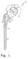
- FIG. 1is a perspective view of a humeral prosthesis which incorporates the features of the present invention therein;
- FIGS. 2 and 3are diagrammatic views which show the humeral prosthesis of FIG. 1 implanted in the body of a patient;
- FIGS. 4 and 5are views similar to FIGS. 2 and 3, but showing a humeral prosthesis having a standard, subhemispherically-shaped head component implanted in the body of the patient;
- FIG. 6is a perspective view of a surgical instrument assembly which incorporates the features of the present invention therein;
- FIGS. 7-15show a patient's shoulder during the various steps of a shoulder replacement procedure for the treatment of cuff tear arthroplasty according to the present invention.
- a modular humeral prosthesis 10which includes a stem component 12 and a head component 14 .
- the stem component 12includes an elongated stem portion 16 and a proximal body portion 18 .
- proximal and distalare terms of reference that indicate a particular portion of a bone or prosthesis component according to the relative disposition of the natural bone or implanted prosthesis.
- proximalindicates the portion of a component nearest the torso
- distalindicates the portion of a component farthest from the torso.
- Directional terms of reference which are used hereininclude superior, inferior, anterior, posterior, medial, and lateral.
- the distal stem portion 16 of the stem component 12is configured to be implanted into the medullary canal 20 of the patient's humerus 22 thereby securing the prosthesis 10 to the humerus 22 .
- the proximal body portion 18 of the stem component 12extends out of the proximal end of the humerus 22 in order for the head component 14 to be secured thereto.
- the head componentincludes a tapered post 24 which is press fit or otherwise received into a corresponding tapered bore 26 defined in the proximal body portion 18 in order to secure the head component 14 to the stem component 12 .
- the head component 14is secured to the stem component 12 prior to implantation of the stem component into the medullary canal 20 of the patient's humerus, although in situ securement of the head component 14 to the stem component 12 is also contemplated.
- the head component 14includes an outer bearing surface 28 .
- the outer bearing surface 28includes a glenoid-bearing portion 30 and an acromion-bearing portion 32 .
- an imaginary line 34divides the outer bearing surface 28 into (1) a first portion (i.e. the glenoid-bearing portion 30 ) which is essentially the same configuration as a standard, subhemispherically-shaped head component, and (2) a second portion (i.e. the acromion-bearing portion 32 ) which, in effect, extends the radial distance of the glenoid-bearing portion 30 .
- the outer bearing surface 28extends a radial distance D in the medial/lateral direction (as viewed in FIGS. 2 and 3 ).
- the radial distance D across which the outer bearing surface 28 extends in the medial/lateral directionis greater than, or equal to, 190 degrees (i.e. D ⁇ 190°).
- the radial distance D across which the outer bearing surface 28 extends in the medial/lateral directionis approximately 220 degrees (i.e. D ⁇ 220°).
- the head component 14may be configured to include an outer bearing surface 28 which extends across any desired radial distance between the range of, for example, 190 degrees and 270 degrees (i.e. 190° ⁇ D ⁇ 270°).
- a prosthetic head component 14 having such a configurationis particularly advantageous during performance of a shoulder replacement procedure in the treatment of cuff tear arthropathy or any other ailment in which the patient's rotator cuff has been torn or otherwise separated from the humerus 22 .
- a shoulder replacement procedurein the treatment of cuff tear arthropathy or any other ailment in which the patient's rotator cuff has been torn or otherwise separated from the humerus 22 .
- hyper-translation of the humeral head (or prosthetic head component) in the superior directionis observed.
- the additional bearing surface area provided by the acromion-bearing portion 32provides a low friction surface for articulating with an inferior surface 38 of the patient's acromion 36 thereby reducing, if not eliminating, pain associated with abduction of the patient's arm.
- FIGS. 4 and 5use of a standard, subhemispherically-shaped head component in regard to the treatment of cuff tear arthropathy is shown in FIGS. 4 and 5.
- the patient's acromion 36articulates with the low friction outer surface of the subhemispherically-shaped head component through only approximately 15° of abduction of the patient's arm.
- a rangei.e. 15°
- the prosthetic head component 14 of the present inventiona significantly greater range of motion may be achieved by use of the prosthetic head component 14 of the present invention.
- the patient's acromion 36articulates with the low friction outer surface bearing surface 28 of the head component 14 through over 60° of abduction of the patient's arm. This is due, in part, to the replacement of the patient's greater tubercle 40 with the acromion-bearing portion 32 of the prosthetic head 14 .
- the natural head 98 of the patient's humerus 22is first resected (see FIG. 7 ).
- the patient's greater tubercle 40is then likewise resected (see FIG. 14 ).
- the glenoid-bearing portion 30 of the head component 14corresponds to the natural head 98 of the patient's humerus 22
- the acromion-bearing portion 32corresponds to the greater tubercle 40 of the patient's humerus 22 .
- the term “correspond” when used in conjunction with a feature of the prosthesis 10is that such a feature is located in approximately the same anatomic position as the natural anatomic feature that it replaced.
- the glenoid-bearing portion 30 of the head component 14“corresponds” to the patient's natural humeral head 98 since it is located in approximately the same anatomical position as the natural head 98 subsequent to replacement thereof, whereas the acromion-bearing portion 32 of the head component 14 “corresponds” to the patient's greater tubercle 40 since it is located in approximately the same location as the greater tubercle 40 subsequent to replacement thereof.
- FIGS. 2 and 3as the patient's arm is abducted from its position in FIG. 2 to its position in FIG. 3 (representing a 60° abduction of the arm in the superior direction), no superior movement of the head component 12 is caused thereby.
- resection of the greater tubercle 40is preferably only performed when the patient is suffering from a massive rotator cuff tear.
- a surgeonwould not typically resect the greater tubercle 40 unless the rotator cuff was already torn or otherwise rendered inoperative.
- the rotator cuffwhen functionally intact, stabilizes the humeral head in the glenoid fossa of the scapula during abduction of the arm thereby allowing the humeral head (or implanted prosthetic head component) to translate only a short distance in the superior direction (e.g. a few millimeters) during abduction of the patient's arm.
- the rotator cuffprevents articulation (e.g. bearing contact) between the humeral head (or implanted prosthetic head component) and the patient's acromion 40 .
- articulatione.g. bearing contact
- the terms “resect”, “resecting”, “resection”, and “resected”, when utilized to refer to the concepts of the present invention,are intended to mean any cutting or removal of a significant portion of the greater tubercle 40 including certain portions of the tubercle 40 utilized for muscle insertion.
- “resection” of the greater tubercle 40is intended to refer to the removal of greater portions of the greater tubercle 40 than would be removed in the case in which the surgeon desires to substantially retain the greater tubercle 40 in its preoperative condition and/or function such as in the case of when the surgeon desires to retain the functionality of the rotator cuff.
- “resection” of the greater tubercle 40may include the removal of bone associated with the greater tubercle to a point beyond the insertion point of the supraspinatus muscle.
- the term “resection” of the greater tubercle 40is intended to mean bone material removal to a degree beyond any slight shaving, smoothening, or “deburring” of the greater tubercle.
- a surgical instrument assemblysuch as a cutting tool guide assembly 50 which is utilized during performance of a shoulder replacement procedure according to the present invention.
- the tool guide assembly 50is particularly useful for guiding a cutting tool such as an oscillating bone saw or osteotome during cutting of the greater tubercle 40 .
- a cutting toolsuch as an oscillating bone saw or osteotome
- the surgeonmay utilize the tool guide assembly 50 during resection of the patient's greater tubercle 40 in order to allow for the use of the prosthetic head component 14 .
- the tool guide assembly 50includes support block 52 , a right guide member or block 54 , a left guide member or block 56 , and a fastener 58 .
- the support block 52includes a channel 60 which defines a mortise 62 for slidably receiving a projection or tenon 64 associated with the guide blocks 54 , 56 .
- the mortise 62 and the tenon 64define a dovetail joint 66 which is utilized to selectively secure one of the guide blocks 54 , 56 to the support block 52 .
- the guide blocks 54 , 56are securable to the humerus 22 of the patient in order to guide the surgeon during cutting of the greater tubercle 40 .
- the support block 52may first be secured to the humerus 22 by use of a positioning member.
- the positioning membermay take any one of a number of different forms.
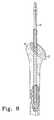
- the positioning membermay take the form of a surgical instrument such as an intramedullary broach 68 (see FIG. 9) or an intramedullary reamer 70 (see FIG. 8 ).
- the support block 52is secured to a proximal end portion of the broach 68 .
- the broach 68includes a distal end portion 72 which is advanced into the medullary canal 20 of the humerus 22 during a broaching operation.
- a proximal end portion 74 of the broach 68extends out of the medullary canal 20 , as shown in FIG. 9 .
- the proximal end portion 74 of the broach 68has a collar 76 having a face 78 and a slot 80 defined therein.
- a positioning tab 82 associated with the support block 52is received into the slot 80 of the broach collar 76 . Thereafter, the fastener 58 is utilized to secure the support block 52 to the broach 68 .
- a threaded end portion 84 of the fasteneris advanced through a countersunk hole 86 defined in the base 88 of the support block 52 and into a counterbored hole 90 defined in the proximal end portion 74 of the broach 68 .
- the threaded end portion 84then threadingly engages a corresponding threaded portion of the counterbored hole 90 so as to advance and retain a bottom surface 92 of the base 88 of the support block 52 into firm contact with the face 78 of the collar 76 thereby securing the support block 52 to the broach 68 (see FIGS. 10 and 11 ).
- a taper assemblysuch as a Morse taper assembly
- a multi-sided postsuch as a hexagon-shaped post, or a clamping mechanism for clamping to the collar 76 may be utilized to secure the support block 52 to the broach 68 .
- the tenon 64 of either the right guide block 54 or the left guide block 56(depending on whether the surgeon is operating on the patient's right or left humerus) is then slid into the mortise 62 of the support block 52 .
- a pair of spring plungers(not shown) are utilized to retain the guide blocks 54 , 56 in a desired location relative to the support block 52 .
- the configuration of the guide blocks 54 , 56 and the support block 52positions a tool guide surface 94 defined in the guide blocks 54 , 56 in a predetermined location relative to the patient's humerus 22 .
- the dimensions of the support block 52 and the guide blocks 54 , 56are predetermined so as to position the tool guide surface 94 in a location in which a surgeon may utilize the guide surface 94 to remove a predetermined portion of the patient's greater tubercle 40 .
- a surgeonutilizes the guide surface 94 to guide a reciprocating bone saw 96 (see FIG. 14) or osteotome (not shown)
- a predetermined portion of the patient's greater tubercle 40may be resected so as to allow for subsequent implantation of the prosthetic head component 14 .
- the implanted broach 68as a positioning member for positioning the support block 52 (and hence the guide blocks 54 , 56 ) in a desired position relative to the patient's humerus 22 .
- certain of such advantagesmay be achieved by utilizing other types of positioning members for positioning the support block 52 (and hence the guide blocks 54 , 56 ) in a desired position relative to the patient's humerus 22 .
- different types of surgical instrumentsmay be utilized as positioning members for positioning the support block 52 (and hence the guide blocks 54 , 56 ) in a desired position relative to the patient's humerus 22 .
- the support block 52may be secured to a portion of the elongated shaft of an intramedullary reamer 70 .
- the support block 52may be secured to a trial implant stem (not shown) or to the implant stem (not shown) itself.
- either the support block 52 , or the guide blocks 54 , 56 themselves,may utilize a positioning member which allows the blocks 52 , 54 , 56 to be secured directly to the humerus 22 thereby eliminating the need to utilize a surgical instrument (e.g. the broach 68 , reamer 70 , trial implant stem, or implant stem) as a positioning member.
- a surgical instrumente.g. the broach 68 , reamer 70 , trial implant stem, or implant stem
- the support block 52 or the guide blocks 54 , 56may be configured to be utilized in conjunction with an attachment mechanism such as a pin assembly, clamping mechanism, or the like (not shown) for securing the same to the humerus 22 in a predetermined position relative to the humerus 22 .
- the positioning membermay also take the form of a fixture assembly or the like (not shown) which positions the support block 52 and/or the guide blocks 54 , 56 in a predetermined position relative to the humerus 22 without actually being secured to the humerus 22 .
- a fixture assemblymay be secured to any one of the number of surgical components which are utilized during performance of a shoulder replacement procedure thereby eliminating the need to secure the support block 52 and/or the guide blocks 54 , 56 to the humerus 22 .
- the concepts of the present inventionmay be utilized to surgically treat a patient suffering from cuff tear arthropathy during performance of a shoulder replacement procedure.
- the head 98 of the patient's humerus 20is first resected by use of, for example, a bone saw 100 .
- a head resection guide assembly 102is first secured to the proximal end portion of the patient's humerus 22 in a conventional manner.
- a cutting guide 104 associated with the assembly 102is then utilized to guide the blade of the bone saw 100 along a desired cutting path (shown as the dashed line 106 ) in order to resect a desired portion of the patient's natural head 98 .
- head resection procedure shown in FIG. 7 and described hereinis quite similar to heretofore utilized head resection procedures which have been used during performance of shoulder replacement procedures in which the patient's rotator cuff is functionally intact (or believed to be functionally intact).
- the medullary canal 20 of the patient's humerus 22is then surgically prepared. Specifically, as shown in FIG. 8, the reamer 70 is advanced into the medullary canal 20 of the patient's humerus 22 in order to ream the same. As with the head resection process described above in regard to FIG. 7, the reaming procedure shown in FIG. 8 and described herein is quite similar to heretofore utilized reaming procedures which have been used during performance of shoulder replacement procedures in which the patient's rotator cuff is functionally intact (or believed to be functionally intact).
- a broaching procedureis performed in order to further prepare the medullary canal 20 for implantation of the stem component 12 of the prosthesis 10 .
- the distal end portion 72 of the broach 68is advanced into the medullary canal 20 of the humerus 22 to a position in which the proximal end portion 74 of the broach 68 extends out of the medullary canal 20 .
- the broach 68is advanced into the medullary canal 20 until fully seated in a position in which the collar 76 of the broach sits substantially flush with the resected surface of the humerus 22 .
- Such broaching of the humerus 22forms a cavity which is substantially equivalent in shape to the proximal body portion 74 of the stem component 68 (albeit slightly smaller to allow for press fitting of the stem component 68 ).
- the broaching procedure shown in FIG. 9 and described hereinis quite similar to heretofore utilized broaching procedures which have been used during performance of shoulder replacement procedures in which the patient's rotator cuff is functionally intact (or believed to be functionally intact).
- the surgeonmay opt to prepare the patient's humerus 22 for implantation of a prosthesis that includes the prosthetic head component 14 .
- the patient's greater tubercle 40must first be resected.
- the steps associated with such resection of the patient's greater tubercle 40are depicted in FIGS. 10-14.
- the first of such steps, as shown in FIG. 10,is the securement of the support block 52 to the broach 68 .
- the positioning tab 82 associated with the support block 52is first advanced into the slot 80 of the broach collar 76 .
- the fastener 58is utilized to secure the support block 52 to the broach 68 .
- the threaded end portion 84 of the fastener 58is advanced through the countersunk hole 86 defined in the base 88 of the support block 52 and into threading engagement with the threaded portion of the counterbored hole 90 .
- Rotation (i.e. tightening) of the fastener 58causes the bottom surface 92 of the base 88 of the support block 52 to be advanced into firm contact with the face 78 of the collar 76 thereby securing the support block 52 to the broach 68 (see FIG. 10 ).
- the surgeonsecures either the right guide block 54 or the left guide block 56 to the support block 52 .
- the surgeonselects the right guide block 54 .
- the surgeonselects the left guide block 56 .
- the tenon 64 of either the right guide block 54 or the left guide block 56is slid into the mortise 62 of the support block 52 .
- the block 54 , 56is advanced to a desired lateral position relative to the humerus 22 at which time a pair of spring plungers (not shown) are utilized to retain the guide blocks 54 , 56 in a desired location relative to the support block 52 .
- the configuration of the guide blocks 54 , 56 and the support block 52positions the tool guide surface 94 defined in the guide blocks 54 , 56 in a predetermined location relative to the patient's humerus 22 .
- the configuration of the support block 52 and the guide blocks 54 , 56when secured to the humerus 22 by use of the implanted broach 68 , position the tool guide surface 94 in a location in which a surgeon may utilize the guide surface 94 to remove a predetermined portion of the patient's greater tubercle 40 .
- a surgeonmay utilize the guide surface 94 to guide a reciprocating bone saw 96 (see FIG. 14) or osteotome (not shown) in order to resect a predetermined portion of the patient's greater tubercle 40 .
- a reciprocating bone saw 96see FIG. 14
- osteotomenot shown
- the surgeondisassembles the tool guide assembly 50 from broach 68 . Specifically, the right guide block 54 or the left guide block 56 (depending on which one was utilized) is detached from the support block 52 . Thereafter, the fastener 58 is unscrewed or otherwise removed from the broach 68 thereby allowing the support block 52 to be lifted away from the face 78 of the collar 76 .
- a rasp or rongeurmay be utilized to extend the length of the cut created by the saw blade of the bone saw 96 in a medial direction to the point in which it intersects with the oblique cut created by the bone saw 100 during resection of the natural head 98 of the patient's humerus 22 (see FIG. 7 ).
- the rasp or rongeurmay also be utilized to remove any protruding bone sections which may subsequently interfere with proper seating of the prosthesis 10 .
- the broach 68is extracted from the medullary canal 22 . Thereafter, the surgeon prepares the prosthesis 10 for implantation into the patient's humerus 22 . Specifically, the surgeon selects both a stem component 12 and a head component 14 from a number of available sizes in order to select components which are properly sized for the patient's anatomy. It should be appreciated that the surgeon may employ any one of numerous techniques to determine the proper size of the stem component 12 and the head component 14 including the use of trial components which may be temporarily implanted into the humerus 22 .
- the surgeonmay secure a trial head component to the broach 68 prior to extraction of the broach 68 in order to determine the proper size of the head component.
- the surgeongenerally selects a head component 14 which is sized quite similarly to the size of the patient's natural anatomy. This is a significant distinction from heretofore utilized methods in which the surgeon would generally select a head component which is larger in size than the natural head thereby “overstuffing” the shoulder joint as described above.
- an impaction stand and associated impactormay be utilized to engage the Morse taper associated with the two components. Specifically, the impaction stand and the impactor are utilized to advance and lock the tapered post 24 of the head component 14 into the corresponding tapered bore 26 defined in the proximal body portion 18 of the stem component 12 in order to secure the head component 14 to the stem component 12 . Thereafter, as shown in FIG. 14, the prosthesis 10 is implanted into the medullary canal 20 of the patient's humerus 22 .
- each of the prosthesis 10 , the cutting tool guide assembly 50 , and the associated surgical method of the present inventionprovides numerous advantages over heretofore designed prostheses, instrument assemblies, and surgical methods.
- use of a prosthesis which includes the prosthetic head component 14is particularly advantageous during performance of a shoulder replacement procedure in the treatment of cuff tear arthropathy or any other ailment in which the rotator cuff has been torn or otherwise irreparably separated from the humerus 22 .
- hyper-translation of the humeral head (or prosthetic head component) in the superior directionis observed.
- the additional bearing surface area provided by the acromion-bearing portion 32provides a low friction surface for articulating with an inferior surface 38 of the patient's acromion 36 thereby reducing, if not eliminating, pain associated with abduction of the patient's arm.
- the prosthetic head component 14may be utilized with existing stem component designs. This is particularly useful since it eliminates the need to design a dedicated stem component for use only with the head component 14 . As a result, a hospital or medical facility may reduce the number of different types of stem components which must be maintained in its inventory since the same stem component may be utilized for either a standard, subhemispherically-shaped prosthetic head component or the head component 14 of the present invention.
- the cutting tool guide assembly 50 of the present inventionprovides for relative ease in the resection of the greater tubercle 40 .
- the tool guide assembly 50provides a surgical instrument assembly which may be utilized by the surgeon to easily and accurately determine the proper cutting plane for resecting the greater tubercle 40 .
- Such an assemblydoes not exist in heretofore designed surgical instrument assemblies.
- the cutting tool guide assembly 50 of the present inventionprovides for relatively efficient resection of the greater tubercle 40 since, in certain exemplary embodiments, it is designed to be secured to the broach 68 . Indeed, by configuring the cutting tool guide assembly 50 to be secured to the broach 68 , additional time consuming surgical steps are avoided. Specifically, by securing the cutting tool guide assembly 50 to the broach 68 , use of additional support members such as additional surgical instruments is avoided.
- the surgical method of the present inventionprovides flexibility in regard to the type of procedure which may be performed by the surgeon.
- the initial steps of the surgical procedure of the present inventione.g. the steps up to and including broaching of the medullary canal 20 of the humerus 22
- the surgeonmay make the decision to resect the greater tubercle 40 (and thereafter utilize the prosthetic head component 14 ) in situ.
- the surgeonmay “convert” the procedure into a procedure which also “replaces” the greater tubercle 40 by simply attaching the cutting guide assembly 50 to the broach 68 (which would be present anyway) and thereafter completing the procedure (including the use of the prosthetic head 14 as opposed to a standard, subhemispherically-shaped head) in the manner described above.
- the surgical procedure of the present inventionis particularly useful in clinical situations in which the surgeon cannot accurately determine preoperatively the condition of the patient's rotator cuff.
Landscapes
- Health & Medical Sciences (AREA)
- Life Sciences & Earth Sciences (AREA)
- Biomedical Technology (AREA)
- Heart & Thoracic Surgery (AREA)
- Veterinary Medicine (AREA)
- Oral & Maxillofacial Surgery (AREA)
- Public Health (AREA)
- Surgery (AREA)
- General Health & Medical Sciences (AREA)
- Engineering & Computer Science (AREA)
- Orthopedic Medicine & Surgery (AREA)
- Transplantation (AREA)
- Animal Behavior & Ethology (AREA)
- Molecular Biology (AREA)
- Medical Informatics (AREA)
- Physical Education & Sports Medicine (AREA)
- Nuclear Medicine, Radiotherapy & Molecular Imaging (AREA)
- Dentistry (AREA)
- Cardiology (AREA)
- Vascular Medicine (AREA)
- Prostheses (AREA)
- Surgical Instruments (AREA)
Abstract
Description
Claims (18)
Priority Applications (8)
| Application Number | Priority Date | Filing Date | Title |
|---|---|---|---|
| US09/767,473US6620197B2 (en) | 2001-01-23 | 2001-01-23 | Method and apparatus for performing a shoulder replacement procedure in the treatment of cuff tear arthropathy |
| EP02250442AEP1224912B1 (en) | 2001-01-23 | 2002-01-22 | Apparatus for resecting a greater tubercle from a humerus |
| EP02250443AEP1228739A3 (en) | 2001-01-23 | 2002-01-22 | Apparatus for performing a shoulder replacement procedure in the treatment of cuff tear arthropathy |
| JP2002014565AJP2002301094A (en) | 2001-01-23 | 2002-01-23 | Method and device for replacing shoulder joint in medical treatment for shoulder tendon disk tearing joint disease |
| AU13533/02AAU784368C (en) | 2001-01-23 | 2002-01-23 | Method and apparatus for performing a shoulder replacement procedure in the treatment of cuff tear arthropathy |
| US10/643,067US20040034431A1 (en) | 2001-01-23 | 2003-08-18 | Method and apparatus for performing a shoulder replacement procedure in the treatment of cuff tear arthropathy |
| US11/503,630US8105385B2 (en) | 2001-01-23 | 2006-08-14 | Procedure for the treatment of cuff tear arthropathy |
| US13/361,114US9510839B2 (en) | 2001-01-23 | 2012-01-30 | Procedure for the treatment of cuff tear arthropathy |
Applications Claiming Priority (1)
| Application Number | Priority Date | Filing Date | Title |
|---|---|---|---|
| US09/767,473US6620197B2 (en) | 2001-01-23 | 2001-01-23 | Method and apparatus for performing a shoulder replacement procedure in the treatment of cuff tear arthropathy |
Related Child Applications (1)
| Application Number | Title | Priority Date | Filing Date |
|---|---|---|---|
| US10/643,067ContinuationUS20040034431A1 (en) | 2001-01-23 | 2003-08-18 | Method and apparatus for performing a shoulder replacement procedure in the treatment of cuff tear arthropathy |
Publications (2)
| Publication Number | Publication Date |
|---|---|
| US20020099445A1 US20020099445A1 (en) | 2002-07-25 |
| US6620197B2true US6620197B2 (en) | 2003-09-16 |
Family
ID=25079593
Family Applications (4)
| Application Number | Title | Priority Date | Filing Date |
|---|---|---|---|
| US09/767,473Expired - LifetimeUS6620197B2 (en) | 2001-01-23 | 2001-01-23 | Method and apparatus for performing a shoulder replacement procedure in the treatment of cuff tear arthropathy |
| US10/643,067AbandonedUS20040034431A1 (en) | 2001-01-23 | 2003-08-18 | Method and apparatus for performing a shoulder replacement procedure in the treatment of cuff tear arthropathy |
| US11/503,630Expired - Fee RelatedUS8105385B2 (en) | 2001-01-23 | 2006-08-14 | Procedure for the treatment of cuff tear arthropathy |
| US13/361,114Expired - Fee RelatedUS9510839B2 (en) | 2001-01-23 | 2012-01-30 | Procedure for the treatment of cuff tear arthropathy |
Family Applications After (3)
| Application Number | Title | Priority Date | Filing Date |
|---|---|---|---|
| US10/643,067AbandonedUS20040034431A1 (en) | 2001-01-23 | 2003-08-18 | Method and apparatus for performing a shoulder replacement procedure in the treatment of cuff tear arthropathy |
| US11/503,630Expired - Fee RelatedUS8105385B2 (en) | 2001-01-23 | 2006-08-14 | Procedure for the treatment of cuff tear arthropathy |
| US13/361,114Expired - Fee RelatedUS9510839B2 (en) | 2001-01-23 | 2012-01-30 | Procedure for the treatment of cuff tear arthropathy |
Country Status (3)
| Country | Link |
|---|---|
| US (4) | US6620197B2 (en) |
| JP (1) | JP2002301094A (en) |
| AU (1) | AU784368C (en) |
Cited By (88)
| Publication number | Priority date | Publication date | Assignee | Title |
|---|---|---|---|---|
| US20040138756A1 (en)* | 2003-01-09 | 2004-07-15 | Nathan Reeder | Method for preparing radial and carpal bones for a wrist prosthesis |
| US20050065612A1 (en)* | 2003-09-24 | 2005-03-24 | Winslow Nathan A. | Extended articular surface resurfacing head |
| US20050143829A1 (en)* | 2003-12-30 | 2005-06-30 | Jeff Ondrla | Joint prosthesis with infinitely positionable head |
| US20050154469A1 (en)* | 2004-01-08 | 2005-07-14 | Angelo Novelli | Acromioclavicular joint prosthesis |
| US20050177241A1 (en)* | 2004-02-05 | 2005-08-11 | Laurent Angibaud | Shoulder prosthesis with humeral fracture stem |
| US20050197708A1 (en)* | 2001-07-11 | 2005-09-08 | Stone Kevin T. | Shoulder prosthesis |
| US20050278031A1 (en)* | 2004-06-15 | 2005-12-15 | Tomier | Set of humeral components for total shoulder prosthesis |
| US20050278030A1 (en)* | 2004-06-15 | 2005-12-15 | Tornier | Glenoidal component, set of such components and shoulder prosthesis incorporating such a glenoidal component |
| US20050288681A1 (en)* | 2004-06-29 | 2005-12-29 | Conrad Klotz | Instrumentation for recording and replicating orthopaedic implant orientation |
| US20060020344A1 (en)* | 2002-07-10 | 2006-01-26 | Biomet Manufacturing Corp. | Shoulder implant assembly |
| US20060058809A1 (en)* | 2004-06-03 | 2006-03-16 | Zink Robert W | Method and apparatus for preparing a glenoid surface |
| US20060069445A1 (en)* | 2004-09-27 | 2006-03-30 | Ondrla Jeffrey M | Extended articulation prosthesis adaptor and associated method |
| US20060069444A1 (en)* | 2004-09-27 | 2006-03-30 | Deffenbaugh Daren L | Glenoid augment and associated method |
| US20060069443A1 (en)* | 2004-09-27 | 2006-03-30 | Deffenbaugh Daren L | Modular glenoid prosthesis and associated method |
| US20060074430A1 (en)* | 2004-09-27 | 2006-04-06 | Deffenbaugh Daren L | Instrument for preparing an implant support surface and associated method |
| US20060074353A1 (en)* | 2004-09-27 | 2006-04-06 | Deffenbaugh Daren L | Glenoid instrumentation and associated method |
| US20060079963A1 (en)* | 2004-10-07 | 2006-04-13 | Regan Hansen | Semiconstrained shoulder prosthetic for treatment of rotator cuff arthropathy |
| US20060142871A1 (en)* | 2004-12-29 | 2006-06-29 | Matthew Biss | System and method for replicating orthopaedic implant orientation |
| US20060142872A1 (en)* | 2004-12-29 | 2006-06-29 | Conrad Klotz | Joint prosthesis with infinitely positionable head |
| US20060195194A1 (en)* | 2005-02-25 | 2006-08-31 | Gunther Stephen B | Shoulder implant for glenoid replacement and methods of use thereof |
| US20060200249A1 (en)* | 2005-03-03 | 2006-09-07 | Laurent Beguin | Humeral implant for shoulder prosthesis |
| US20070078519A1 (en)* | 2005-09-30 | 2007-04-05 | Klotz Conrad L | Joint prosthesis with positionable head |
| US20070142918A1 (en)* | 2003-10-08 | 2007-06-21 | Stone Kevin T | Shoulder implant assembly |
| US20070198094A1 (en)* | 2006-02-17 | 2007-08-23 | Biomet Manufacturing Corp. | Adaptor prosthesis kit |
| US20070225821A1 (en)* | 2006-03-21 | 2007-09-27 | Axiom Orthopaedics, Inc. | Femoral and humeral stem geometry and implantation method for orthopedic joint reconstruction |
| US20080021564A1 (en)* | 2006-07-20 | 2008-01-24 | Gunther Stephen B | Humeral head resurfacing implant and methods of use thereof |
| US20080161823A1 (en)* | 2006-09-29 | 2008-07-03 | Depuy Products, Inc. | Instrument for modular orthopaedic prosthesis |
| US20080228281A1 (en)* | 2005-09-16 | 2008-09-18 | Zimmer Gmbh | Insert and Shell of a Joint Ball Receptacle |
| US20080234829A1 (en)* | 2007-03-20 | 2008-09-25 | Dvo Extremity Solutions, Llc. | Humeral head augment device and method for use in a shoulder prosthesis |
| US20080294268A1 (en)* | 2005-11-18 | 2008-11-27 | Zimmer Gmbh | Base Platform for an Artificial Joint |
| US7462197B2 (en) | 2004-06-15 | 2008-12-09 | Tornier Sas | Glenoidal component of a shoulder prosthesis, set of elements constituting such a component and total shoulder prosthesis incorporating such a component |
| US7465319B2 (en) | 2003-12-19 | 2008-12-16 | Tornier Sas | Shoulder or hip prosthesis and process for fitting same |
| US7470287B2 (en) | 2004-06-28 | 2008-12-30 | Tornier Sas | Shoulder or hip prosthesis |
| US20090192621A1 (en)* | 2003-10-08 | 2009-07-30 | Biomet Manufacturing Corp. | Shoulder Implant Assembly |
| US20090254091A1 (en)* | 2008-04-04 | 2009-10-08 | Long Jack F | Humeral rotating burr guide |
| US20090292364A1 (en)* | 2008-05-21 | 2009-11-26 | Linares Medical Devices, Llc | Shoulder implant with first and second composite sub-assemblies and improved mounting anchors for establishing a secure joint |
| US20090312838A1 (en)* | 2008-06-11 | 2009-12-17 | Depuy Products, Inc. | Joint Prosthesis with Positionable Head |
| US7678150B2 (en) | 2004-06-15 | 2010-03-16 | Tornier Sas | Total shoulder prosthesis of an inverted type |
| US20100249938A1 (en)* | 2005-02-25 | 2010-09-30 | Gunther Stephen B | Methods and devices for less invasive glenoid replacement |
| US7846162B2 (en) | 2005-05-18 | 2010-12-07 | Sonoma Orthopedic Products, Inc. | Minimally invasive actuable bone fixation devices |
| US20110035014A1 (en)* | 2006-01-20 | 2011-02-10 | Zimmer Gmbh | Humeral component |
| US7887544B2 (en) | 2003-03-10 | 2011-02-15 | Tornier Sas | Ancillary tool for positioning a glenoid implant |
| US7909825B2 (en) | 2006-11-22 | 2011-03-22 | Sonoma Orthepedic Products, Inc. | Fracture fixation device, tools and methods |
| US20110118846A1 (en)* | 2009-11-18 | 2011-05-19 | Biomet Manufacturing Corp. | Shoulder prosthetic |
| US8075628B2 (en) | 2002-04-25 | 2011-12-13 | Zimmer, Inc. | Modular bone implant, tools, and method |
| US8080063B2 (en) | 2006-04-13 | 2011-12-20 | Tornier Sas | Glenoid component with an anatomically optimized keel |
| US20120130500A1 (en)* | 2001-01-23 | 2012-05-24 | Depuy Products, Inc. | Procedure for the Treatment of Cuff Tear Arthropathy |
| US8231683B2 (en) | 2009-12-08 | 2012-07-31 | Depuy Products, Inc. | Shoulder prosthesis assembly having glenoid rim replacement structure |
| US8241365B2 (en) | 2008-12-23 | 2012-08-14 | Depuy Products, Inc. | Shoulder prosthesis with vault-filling structure having bone-sparing configuration |
| US8277511B2 (en) | 2006-04-21 | 2012-10-02 | Tornier Sas | Shoulder or hip prosthesis and method for setting same |
| US8287541B2 (en) | 2005-05-18 | 2012-10-16 | Sonoma Orthopedic Products, Inc. | Fracture fixation device, tools and methods |
| US8465548B2 (en) | 2010-11-24 | 2013-06-18 | DePuy Synthes Products, LLC | Modular glenoid prosthesis |
| US8480750B2 (en) | 2010-11-24 | 2013-07-09 | DePuy Synthes Products, LLC | Modular glenoid prosthesis |
| US8702802B2 (en) | 2011-08-29 | 2014-04-22 | Linares Medical Devices, Llc | Knee implant assembly with rotary bearing supported and traveling surfaces |
| US8702800B2 (en) | 2011-08-23 | 2014-04-22 | Linares Medical Devices, Llc | Multi-component shoulder implant assembly with dual articulating surfaces |
| US8702804B2 (en) | 2011-12-02 | 2014-04-22 | Biomet Manufacturing, Llc | Variable prosthesis |
| US8753403B2 (en) | 2011-08-30 | 2014-06-17 | Linares Medical Devices, Llc | Multi-component knee implant assembly with combined articulating and belt support and traveling surfaces |
| US8795379B2 (en) | 2001-07-11 | 2014-08-05 | Biomet Manufacturing, Llc | Variable prosthesis |
| US8864835B2 (en) | 2011-08-24 | 2014-10-21 | Linares Medical Devices, Llc | Multi-component knee implant assembly with multiple articulating and traveling surfaces |
| US8864834B2 (en) | 2007-01-30 | 2014-10-21 | Tornier Sas | Method and apparatus for fitting a shoulder prosthesis |
| US8882776B2 (en)* | 2003-03-31 | 2014-11-11 | DePuy Synthes Products, LLC | Extended articulation orthopaedic implant |
| US8961516B2 (en) | 2005-05-18 | 2015-02-24 | Sonoma Orthopedic Products, Inc. | Straight intramedullary fracture fixation devices and methods |
| US8974458B2 (en) | 2003-03-31 | 2015-03-10 | DePuy Synthes Products, LLC | Arthroplasty instruments and associated method |
| US8974536B2 (en) | 2007-01-30 | 2015-03-10 | Tornier Sas | Intra-articular joint replacement |
| US9060820B2 (en) | 2005-05-18 | 2015-06-23 | Sonoma Orthopedic Products, Inc. | Segmented intramedullary fracture fixation devices and methods |
| US9107758B2 (en) | 2003-03-31 | 2015-08-18 | DePuy Synthes Products, Inc. | Bone preparation tool kit and associated method |
| US9132016B2 (en) | 2010-05-26 | 2015-09-15 | Topsfield Medical Gmbh | Implantable shoulder prostheses |
| US9155574B2 (en) | 2006-05-17 | 2015-10-13 | Sonoma Orthopedic Products, Inc. | Bone fixation device, tools and methods |
| US9408652B2 (en) | 2010-04-27 | 2016-08-09 | Tornier Sas | Intra-articular joint replacement and method |
| US9433507B2 (en) | 2006-03-21 | 2016-09-06 | Tornier, Inc. | Non-spherical articulating surfaces in shoulder and hip replacement |
| US9474619B2 (en) | 2006-03-21 | 2016-10-25 | Tornier, Inc. | Glenoid component with improved fixation stability |
| US9681960B2 (en) | 2014-05-16 | 2017-06-20 | Howmedica Osteonics Corp. | Guides for fracture system |
| US9770278B2 (en) | 2014-01-17 | 2017-09-26 | Arthrex, Inc. | Dual tip guide wire |
| US9814499B2 (en) | 2014-09-30 | 2017-11-14 | Arthrex, Inc. | Intramedullary fracture fixation devices and methods |
| US9849000B2 (en) | 2003-03-31 | 2017-12-26 | DePuy Synthes Products, Inc. | Punch, implant and associated method |
| US10022237B2 (en) | 2011-08-23 | 2018-07-17 | Linares Medical Devices, Llc | Multi-component implant assembly with dual articulating and/or rotating surfaces |
| US20180256217A1 (en)* | 2015-09-18 | 2018-09-13 | Ortho-Space Ltd. | Intramedullary fixated subacromial spacers |
| US10492926B1 (en) | 2014-09-04 | 2019-12-03 | Shoulder Innovations, Inc. | Alignment guide for humeral or femoral stem replacement prostheses |
| US10575968B2 (en) | 2014-05-16 | 2020-03-03 | Howmedica Osteonics Corp. | Guides for fracture system |
| US10631993B2 (en) | 2010-10-22 | 2020-04-28 | Tornier, Inc. | Set of glenoid components for a shoulder prosthesis |
| US10813769B2 (en) | 2018-07-24 | 2020-10-27 | DePuy Synthes Products, Inc. | Baseplate of a modular shoulder joint prosthesis and related methods for implanting the same |
| US11065125B2 (en) | 2017-04-14 | 2021-07-20 | Shoulder Innovations, Inc. | Total shoulder prosthesis having inset glenoid implant convertible from anatomic to reverse |
| US11344423B1 (en) | 2009-03-05 | 2022-05-31 | Howmedica Osteonics Corp. | Glenoid implant anchor post |
| USD977643S1 (en) | 2019-03-12 | 2023-02-07 | Shoulder Innovations, Inc. | Humeral stem implant |
| US20230090753A1 (en) | 2019-03-11 | 2023-03-23 | Shoulder Innovations, Inc. | Total reverse shoulder systems and methods |
| US11957595B2 (en) | 2005-02-25 | 2024-04-16 | Shoulder Innovations, Inc. | Methods and devices for less invasive glenoid replacement |
| USD1048403S1 (en) | 2023-02-04 | 2024-10-22 | Catalyst Orthoscience Inc. | Arthroplasty prosthesis |
| US12138172B2 (en) | 2018-04-30 | 2024-11-12 | Shoulder Innovations, Inc. | Inset/onlay glenoid, porous coated convertible glenoid, and humeral heads with textured undersides |
Families Citing this family (50)
| Publication number | Priority date | Publication date | Assignee | Title |
|---|---|---|---|---|
| US8317871B2 (en) | 2001-07-27 | 2012-11-27 | Biomet Manufacturing Corp. | Modular humeral head resurfacing system |
| US8753402B2 (en) | 2001-07-27 | 2014-06-17 | Biomet Manufacturing, Llc | Modular humeral head resurfacing system |
| EP1415621B1 (en)* | 2002-08-21 | 2016-09-14 | Zimmer GmbH | Shoulder prothesis |
| US7338498B2 (en)* | 2003-03-31 | 2008-03-04 | Depuy Products, Inc. | Prosthetic implant, trial and associated method |
| US7527631B2 (en)* | 2003-03-31 | 2009-05-05 | Depuy Products, Inc. | Arthroplasty sizing gauge |
| US20040193278A1 (en)* | 2003-03-31 | 2004-09-30 | Maroney Brian J. | Articulating surface replacement prosthesis |
| US20040193276A1 (en)* | 2003-03-31 | 2004-09-30 | Maroney Brian J. | Modular articulating surface replacement prosthesis |
| FR2859099B1 (en)* | 2003-08-25 | 2006-01-06 | Tornier Sa | GLENOIDAL COMPONENT OF SHOULDER PROSTHESIS AND TOTAL SHOULDER PROSTHESIS INCORPORATING SUCH COMPONENT |
| US20050049710A1 (en)* | 2003-08-28 | 2005-03-03 | O'driscoll Shawn W. | Prosthesis for partial replacement of an articulating surface on bone |
| US7879042B2 (en)* | 2004-03-05 | 2011-02-01 | Depuy Products, Inc. | Surface replacement extractor device and associated method |
| US7135044B2 (en)* | 2004-03-09 | 2006-11-14 | Howmedics Osteonics Corp. | Modular prosthesis kits |
| US7935399B2 (en)* | 2004-09-02 | 2011-05-03 | Grupo Petrotemex, S.A. De C.V. | Low melting polyester polymers |
| US20080004710A1 (en)* | 2006-06-30 | 2008-01-03 | Howmedica Osteonics Corp. | Femoral head resurfacing |
| US20080109085A1 (en)* | 2006-11-03 | 2008-05-08 | Howmedica Osteonics Corp. | Method and apparatus for hip femoral resurfacing tooling |
| US20090062928A1 (en)* | 2007-09-05 | 2009-03-05 | Mark Pitkin | In-bone implantable shaft for prosthetic joints or for direct skeletal attachment of external limb prostheses and method of its installation |
| GB2471290A (en)* | 2009-06-23 | 2010-12-29 | Keith Borowsky | Joint repair apparatus |
| US8556901B2 (en) | 2009-12-31 | 2013-10-15 | DePuy Synthes Products, LLC | Reciprocating rasps for use in an orthopaedic surgical procedure |
| US8506569B2 (en) | 2009-12-31 | 2013-08-13 | DePuy Synthes Products, LLC | Reciprocating rasps for use in an orthopaedic surgical procedure |
| US8715356B2 (en)* | 2010-04-13 | 2014-05-06 | Biomet Manufacturing, Llc | Prosthetic having a modular soft tissue fixation mechanism |
| US8486076B2 (en) | 2011-01-28 | 2013-07-16 | DePuy Synthes Products, LLC | Oscillating rasp for use in an orthopaedic surgical procedure |
| US9421106B2 (en) | 2011-12-07 | 2016-08-23 | Howmedica Osteonics Corp. | Reverse shoulder baseplate with alignment guide for glenosphere |
| EP2787901B1 (en) | 2011-12-09 | 2017-06-07 | Howmedica Osteonics Corp. | Surgical reaming instrument for shaping a bone cavity |
| WO2013102089A1 (en) | 2011-12-30 | 2013-07-04 | Howmedica Osteonics Corp. | Systems for preparing bone voids to receive a prosthesis |
| US8663334B2 (en)* | 2012-05-31 | 2014-03-04 | Howmedica Osteonics Corp. | Lateral entry insert for cup trial |
| US8906102B2 (en)* | 2012-05-31 | 2014-12-09 | Howmedica Osteonics Corp. | Lateral entry insert for cup trial |
| US8936645B1 (en) | 2012-11-01 | 2015-01-20 | Marcos V. Masson | Surgical process for resurfacing a humeral head |
| US9814471B2 (en) | 2013-03-11 | 2017-11-14 | Catalyst Orthoscience Inc. | Glenoid arthroplasty and offset reamers |
| US11007063B2 (en) | 2013-03-11 | 2021-05-18 | Catalyst Orthoscience Inc. | Offset reamers |
| USD730522S1 (en) | 2013-03-11 | 2015-05-26 | Catalyst Orthopaedics Llc | Implant |
| US9814588B2 (en) | 2015-08-10 | 2017-11-14 | Catalyst Orthoscience Inc. | Glenoid arthroplasty with multi-directional fixation |
| US20170319348A1 (en) | 2015-08-10 | 2017-11-09 | Catalyst Orthoscience Inc. | Arthroplasty prostheses with multi-axis fixation |
| US10973646B2 (en) | 2013-03-11 | 2021-04-13 | Catalyst Orthoscience Inc. | Stabilized drill guide |
| US9526513B2 (en) | 2013-03-13 | 2016-12-27 | Howmedica Osteonics Corp. | Void filling joint prosthesis and associated instruments |
| US9289306B2 (en) | 2013-03-15 | 2016-03-22 | Catalyst Orthopaedics Llc | Humeral arthroplasty |
| USD735338S1 (en) | 2013-10-31 | 2015-07-28 | Catalyst Orthopaedics Llc | Humeral component for shoulder arthroplasty |
| US10456264B2 (en) | 2014-01-24 | 2019-10-29 | Tornier, Inc. | Humeral implant anchor system |
| US12023253B2 (en) | 2014-01-24 | 2024-07-02 | Howmedica Osteonics Corp. | Humeral implant anchor system |
| US10149763B2 (en) | 2015-01-12 | 2018-12-11 | Howmedica Osteonics Corp. | Multipurpose void filling prosthesis |
| US10390972B2 (en) | 2016-01-15 | 2019-08-27 | Howmedica Osteonics Corp. | Humeral trial adaptor |
| US10463499B2 (en) | 2016-03-25 | 2019-11-05 | Tornier, Inc. | Stemless shoulder implant with fixation components |
| US11129724B2 (en) | 2016-07-28 | 2021-09-28 | Howmedica Osteonics Corp. | Stemless prosthesis anchor component |
| DE102017101135A1 (en) | 2017-01-20 | 2018-07-26 | Aesculap Ag | Medical Instrument |
| MX2020003194A (en) | 2017-09-25 | 2020-12-09 | Howmedica Osteonics Corp | Patient specific stemless prosthesis anchor components. |
| US11399948B2 (en) | 2017-12-11 | 2022-08-02 | Howmedica Osteonics Corp. | Stemless prosthesis anchor components and kits |
| EP4257090A3 (en) | 2018-10-02 | 2023-12-13 | Howmedica Osteonics Corp. | Shoulder prosthesis components and assemblies |
| CN111134904B (en)* | 2018-11-06 | 2022-03-01 | 贵州澳特拉斯科技有限公司 | Bionic artificial hip joint |
| US11571310B2 (en) | 2019-04-03 | 2023-02-07 | Catalyst Orthoscience Inc. | Stemmed implant |
| USD951449S1 (en) | 2019-10-01 | 2022-05-10 | Howmedica Osteonics Corp. | Humeral implant |
| EP4527357A3 (en) | 2019-10-01 | 2025-06-04 | Howmedica Osteonics Corporation | Shoulder prosthesis components and assemblies |
| CN118680735B (en)* | 2024-07-15 | 2025-03-07 | 北京力达康科技有限公司 | Modularized shoulder joint prosthesis and implantation method thereof |
Citations (24)
| Publication number | Priority date | Publication date | Assignee | Title |
|---|---|---|---|---|
| DE2041929A1 (en) | 1969-08-25 | 1971-03-11 | Nat Res Dev | Prosthetic shoulder joint |
| DE2400650A1 (en) | 1973-01-12 | 1974-07-18 | Nat Res Dev | ENDOPROSTHETIC SHOULDER-JOINT CUP ATTACHED TO THE SHOULDER BLADE |
| US3979778A (en)* | 1976-01-14 | 1976-09-14 | Stroot Jerome H | Shoulder prosthesis |
| US4042980A (en) | 1975-03-13 | 1977-08-23 | National Research Development Corporation | Endoprosthetic shoulder joint device |
| DE3023354A1 (en) | 1979-10-04 | 1981-04-09 | Gebrüder Sulzer AG, 8401 Winterthur | JOINT HEAD FOR A BALL JOINT PROSTHESIS |
| US4279041A (en) | 1978-07-06 | 1981-07-21 | Buchholz Hans Wilhelm | Endoprosthesis composed of a socket and a head receivable and lockable in the socket |
| US4355427A (en) | 1979-06-22 | 1982-10-26 | Wolfgang Schneider | Artificial humerus head |
| US4550450A (en) | 1984-07-24 | 1985-11-05 | Kinnett James G | Total shoulder prosthesis system |
| FR2567019A1 (en) | 1984-07-06 | 1986-01-10 | Fournier Gilles | Method for retaining the parts of an articular internal prosthesis. |
| US4662888A (en) | 1984-08-01 | 1987-05-05 | National Research Development Corporation | Endoprosthetic bone joint components |
| US4865605A (en)* | 1988-02-02 | 1989-09-12 | Dines David M | Modular shoulder prosthesis |
| US5080673A (en) | 1988-02-03 | 1992-01-14 | Intermedics Orthopedics, Inc. | Glenoid prosthesis and method of use |
| EP0485250A1 (en)* | 1990-11-07 | 1992-05-13 | Rasec Communication | Electronic data display device |
| US5282865A (en) | 1992-06-22 | 1994-02-01 | Osteonics Corp. | Humeral shoulder prosthesis |
| US5330531A (en) | 1991-12-10 | 1994-07-19 | Howmedica Gmbh | Humeral endoprosthesis |
| US5458653A (en) | 1991-07-15 | 1995-10-17 | Smith & Nephew Richards, Inc. | Prosthetic implants with bioabsorbable coatings |
| US5489310A (en) | 1994-06-27 | 1996-02-06 | Mikhail; W. E. Michael | Universal glenoid shoulder prosthesis and method for implanting |
| GB2297257A (en) | 1995-01-24 | 1996-07-31 | Corin Medical Ltd | Shoulder prosthesis with meniscal component |
| US5549682A (en) | 1994-06-16 | 1996-08-27 | Roy; Stephen C. | Shoulder joint prosthesis with angular adjustment |
| US5658340A (en) | 1993-08-16 | 1997-08-19 | Howmedica Gmbh | Endoprosthesis for a shoulder joint |
| EP0845250A2 (en) | 1996-11-30 | 1998-06-03 | Depuy International Limited | An osteoprosthesis component |
| US5944758A (en)* | 1996-10-09 | 1999-08-31 | Minnesota Mining And Manufacturing Company | Shoulder prosthesis |
| US5944757A (en)* | 1995-09-22 | 1999-08-31 | Medinov-Amp | Total trochitero-acromial shoulder prosthesis |
| US6045582A (en)* | 1998-09-25 | 2000-04-04 | Sulzer Orthopedics Inc. | Implantable humeral shoulder prosthesis having extended articular surface |
Family Cites Families (39)
| Publication number | Priority date | Publication date | Assignee | Title |
|---|---|---|---|---|
| US3978528A (en) | 1975-06-26 | 1976-09-07 | Howmedica, Inc. | Bone and joint prosthesis |
| US4045826A (en) | 1977-02-09 | 1977-09-06 | Stroot Jerome H | Glenoid component for shoulder prosthesis |
| EP0005612B1 (en) | 1978-05-12 | 1981-12-30 | National Research Development Corporation | Endoprosthetic joint devices |
| US4261062A (en) | 1979-03-22 | 1981-04-14 | The Regents Of The University Of California | Natural shoulder joint prosthesis |
| US4645507A (en) | 1982-09-02 | 1987-02-24 | Gmt Gesellschaft Fur Medizinische Technik Mbh | Prosthesis |
| FR2545352B1 (en) | 1983-05-02 | 1990-01-19 | Gabard Jean Jacques | SHOULDER PROSTHESIS |
| US5314479A (en) | 1986-08-15 | 1994-05-24 | Depuy Inc. | Modular prosthesis |
| US4759350A (en) | 1986-10-17 | 1988-07-26 | Dunn Harold K | Instruments for shaping distal femoral and proximal tibial surfaces |
| FR2610515A1 (en) | 1987-02-09 | 1988-08-12 | Jean Lannelongue | SHOULDER PROSTHESIS |
| US4919670A (en) | 1988-02-03 | 1990-04-24 | Intermedics Orthopedics, Inc. | Modular humeral prosthesis |
| US4893619A (en) | 1988-02-04 | 1990-01-16 | Intermedics Orthopedics, Inc. | Humeral osteotomy guide |
| US5041117A (en) | 1989-08-31 | 1991-08-20 | Boehringer Mannheim Corporation | Elbow arthroplasty instrumentation and surgical procedure |
| US5108396A (en) | 1990-06-07 | 1992-04-28 | Smith & Nephew Richards Inc. | Intramedullary referenced humeral head resection guide |
| US5571193A (en) | 1992-03-12 | 1996-11-05 | Kampner; Stanley L. | Implant with reinforced resorbable stem |
| US5234432A (en) | 1992-03-13 | 1993-08-10 | Brown Byron L | Method and apparatus for definitive cutting of a femur |
| US5489309A (en) | 1993-01-06 | 1996-02-06 | Smith & Nephew Richards Inc. | Modular humeral component system |
| US5961555A (en) | 1998-03-17 | 1999-10-05 | Huebner; Randall J. | Modular shoulder prosthesis |
| US5910171A (en) | 1993-03-12 | 1999-06-08 | Hospital For Joint Diseases | Components for a modular shoulder and hip prosthesis |
| FR2703241B1 (en) | 1993-03-30 | 1995-05-19 | Landanger Landos | Head for modular shoulder and hip prosthesis. |
| US5720752A (en) | 1993-11-08 | 1998-02-24 | Smith & Nephew, Inc. | Distal femoral cutting guide apparatus with anterior or posterior referencing for use in knee joint replacement surgery |
| US5540695A (en) | 1994-02-18 | 1996-07-30 | Howmedica Inc. | Osteotomy cutting guide |
| US5507817A (en) | 1994-02-22 | 1996-04-16 | Kirschner Medical Corporation | Modular humeral prosthesis for reconstruction of the humerus |
| FR2727002B1 (en) | 1994-11-18 | 1997-01-03 | Tornier Sa | HUMERAL PROSTHESIS IN SPHERE |
| US5683397A (en) | 1995-02-15 | 1997-11-04 | Smith & Nephew, Inc. | Distal femoral cutting guide apparatus for use in knee joint replacement surgery |
| US5728161A (en) | 1995-06-08 | 1998-03-17 | Depuy Orthopedics, Inc. | Large taper modular shoulder prosthesis |
| US5817097A (en) | 1995-08-03 | 1998-10-06 | Synvasive Technology, Inc. | Bone saw blade guide with magnet |
| US5776194A (en) | 1996-04-25 | 1998-07-07 | Nuvana Medical Innovations, Llc | Intermedullary rod apparatus and methods of repairing proximal humerus fractures |
| US5779710A (en) | 1996-06-21 | 1998-07-14 | Matsen, Iii; Frederick A. | Joint replacement method and apparatus |
| FR2751868B1 (en) | 1996-08-02 | 1999-04-16 | Tornier Sa | ADJUSTED PROSTHESIS OF THE SUPERIOR END OF THE HUMERUS |
| US5876459A (en) | 1996-08-30 | 1999-03-02 | Powell; Douglas Hunter | Adjustable modular orthopedic implant |
| US5906644A (en) | 1996-08-30 | 1999-05-25 | Powell; Douglas Hunter | Adjustable modular orthopedic implant |
| US5782920A (en) | 1996-11-14 | 1998-07-21 | Johnson & Johnson Professional, Inc. | Offset coupling for joint prosthesis |
| US5980526A (en) | 1997-02-12 | 1999-11-09 | Orthopaedic Innovations, Inc. | Wedge osteotomy device including a guide for controlling osteotomy depth |
| GB2322304B (en) | 1997-02-21 | 2001-03-14 | Biomet Ltd | Surgical Tool Aligning Device |
| GB9707853D0 (en) | 1997-04-18 | 1997-06-04 | Headcorn Instrumentation Ltd | Prosthesis |
| US5928285A (en) | 1997-05-30 | 1999-07-27 | Bristol-Myers Squibb Co. | Orthopaedic implant having an articulating surface with a conforming and translational surface |
| GB2331016A (en) | 1997-11-06 | 1999-05-12 | Depuy Int Ltd | Intramedullary bone resection guide |
| US6283999B1 (en) | 1999-01-29 | 2001-09-04 | Depuy Orthopaedics, Inc. | Shoulder prothesis with humeral fracture stem |
| US6620197B2 (en)* | 2001-01-23 | 2003-09-16 | Depuy Orthopaedics, Inc. | Method and apparatus for performing a shoulder replacement procedure in the treatment of cuff tear arthropathy |
- 2001
- 2001-01-23USUS09/767,473patent/US6620197B2/ennot_activeExpired - Lifetime
- 2002
- 2002-01-23JPJP2002014565Apatent/JP2002301094A/enactivePending
- 2002-01-23AUAU13533/02Apatent/AU784368C/ennot_activeExpired
- 2003
- 2003-08-18USUS10/643,067patent/US20040034431A1/ennot_activeAbandoned
- 2006
- 2006-08-14USUS11/503,630patent/US8105385B2/ennot_activeExpired - Fee Related
- 2012
- 2012-01-30USUS13/361,114patent/US9510839B2/ennot_activeExpired - Fee Related
Patent Citations (25)
| Publication number | Priority date | Publication date | Assignee | Title |
|---|---|---|---|---|
| DE2041929A1 (en) | 1969-08-25 | 1971-03-11 | Nat Res Dev | Prosthetic shoulder joint |
| US3694820A (en) | 1969-08-25 | 1972-10-03 | Nat Res Dev | Prosthetic shoulder joint |
| DE2400650A1 (en) | 1973-01-12 | 1974-07-18 | Nat Res Dev | ENDOPROSTHETIC SHOULDER-JOINT CUP ATTACHED TO THE SHOULDER BLADE |
| US4042980A (en) | 1975-03-13 | 1977-08-23 | National Research Development Corporation | Endoprosthetic shoulder joint device |
| US3979778A (en)* | 1976-01-14 | 1976-09-14 | Stroot Jerome H | Shoulder prosthesis |
| US4279041A (en) | 1978-07-06 | 1981-07-21 | Buchholz Hans Wilhelm | Endoprosthesis composed of a socket and a head receivable and lockable in the socket |
| US4355427A (en) | 1979-06-22 | 1982-10-26 | Wolfgang Schneider | Artificial humerus head |
| DE3023354A1 (en) | 1979-10-04 | 1981-04-09 | Gebrüder Sulzer AG, 8401 Winterthur | JOINT HEAD FOR A BALL JOINT PROSTHESIS |
| FR2567019A1 (en) | 1984-07-06 | 1986-01-10 | Fournier Gilles | Method for retaining the parts of an articular internal prosthesis. |
| US4550450A (en) | 1984-07-24 | 1985-11-05 | Kinnett James G | Total shoulder prosthesis system |
| US4662888A (en) | 1984-08-01 | 1987-05-05 | National Research Development Corporation | Endoprosthetic bone joint components |
| US4865605A (en)* | 1988-02-02 | 1989-09-12 | Dines David M | Modular shoulder prosthesis |
| US5080673A (en) | 1988-02-03 | 1992-01-14 | Intermedics Orthopedics, Inc. | Glenoid prosthesis and method of use |
| EP0485250A1 (en)* | 1990-11-07 | 1992-05-13 | Rasec Communication | Electronic data display device |
| US5458653A (en) | 1991-07-15 | 1995-10-17 | Smith & Nephew Richards, Inc. | Prosthetic implants with bioabsorbable coatings |
| US5330531A (en) | 1991-12-10 | 1994-07-19 | Howmedica Gmbh | Humeral endoprosthesis |
| US5282865A (en) | 1992-06-22 | 1994-02-01 | Osteonics Corp. | Humeral shoulder prosthesis |
| US5658340A (en) | 1993-08-16 | 1997-08-19 | Howmedica Gmbh | Endoprosthesis for a shoulder joint |
| US5549682A (en) | 1994-06-16 | 1996-08-27 | Roy; Stephen C. | Shoulder joint prosthesis with angular adjustment |
| US5489310A (en) | 1994-06-27 | 1996-02-06 | Mikhail; W. E. Michael | Universal glenoid shoulder prosthesis and method for implanting |
| GB2297257A (en) | 1995-01-24 | 1996-07-31 | Corin Medical Ltd | Shoulder prosthesis with meniscal component |
| US5944757A (en)* | 1995-09-22 | 1999-08-31 | Medinov-Amp | Total trochitero-acromial shoulder prosthesis |
| US5944758A (en)* | 1996-10-09 | 1999-08-31 | Minnesota Mining And Manufacturing Company | Shoulder prosthesis |
| EP0845250A2 (en) | 1996-11-30 | 1998-06-03 | Depuy International Limited | An osteoprosthesis component |
| US6045582A (en)* | 1998-09-25 | 2000-04-04 | Sulzer Orthopedics Inc. | Implantable humeral shoulder prosthesis having extended articular surface |
Cited By (206)
| Publication number | Priority date | Publication date | Assignee | Title |
|---|---|---|---|---|
| US9510839B2 (en)* | 2001-01-23 | 2016-12-06 | DePuy Synthes Products, Inc. | Procedure for the treatment of cuff tear arthropathy |
| US20120130500A1 (en)* | 2001-01-23 | 2012-05-24 | Depuy Products, Inc. | Procedure for the Treatment of Cuff Tear Arthropathy |
| US20050197708A1 (en)* | 2001-07-11 | 2005-09-08 | Stone Kevin T. | Shoulder prosthesis |
| US8236059B2 (en) | 2001-07-11 | 2012-08-07 | Biomet Manufacturing, Inc. | Shoulder prothesis |
| US20110035015A1 (en)* | 2001-07-11 | 2011-02-10 | Biomet Manufacturing Corp. | Shoulder prothesis |
| US10603181B2 (en) | 2001-07-11 | 2020-03-31 | Biomet Manufacturing, Llc | Shoulder prosthesis |
| US8795379B2 (en) | 2001-07-11 | 2014-08-05 | Biomet Manufacturing, Llc | Variable prosthesis |
| US8906103B2 (en) | 2001-07-11 | 2014-12-09 | Biomet Manufacturing, Llc | Shoulder prosthesis |
| US7819923B2 (en) | 2001-07-11 | 2010-10-26 | Biomet Manufacturing Corp. | Shoulder prosthesis |
| US9700423B2 (en) | 2001-07-11 | 2017-07-11 | Biomet Manufacturing, Llc | Shoulder prosthesis |
| US9241803B2 (en) | 2001-07-11 | 2016-01-26 | Biomet Manufacturing, Llc. | Shoulder prosthesis |
| US8075628B2 (en) | 2002-04-25 | 2011-12-13 | Zimmer, Inc. | Modular bone implant, tools, and method |
| US8062376B2 (en) | 2002-07-10 | 2011-11-22 | Biomet Manufacturing Corp. | Shoulder implant assembly |
| US20060020344A1 (en)* | 2002-07-10 | 2006-01-26 | Biomet Manufacturing Corp. | Shoulder implant assembly |
| US6827741B2 (en)* | 2003-01-09 | 2004-12-07 | Zimmer Technology, Inc. | Method for preparing radial and carpal bones for a wrist prosthesis |
| US20040138756A1 (en)* | 2003-01-09 | 2004-07-15 | Nathan Reeder | Method for preparing radial and carpal bones for a wrist prosthesis |
| US8187282B2 (en) | 2003-03-10 | 2012-05-29 | Tornier Sas | Ancillary tool for positioning a glenoid implant |
| US7887544B2 (en) | 2003-03-10 | 2011-02-15 | Tornier Sas | Ancillary tool for positioning a glenoid implant |
| US9107758B2 (en) | 2003-03-31 | 2015-08-18 | DePuy Synthes Products, Inc. | Bone preparation tool kit and associated method |
| US9849000B2 (en) | 2003-03-31 | 2017-12-26 | DePuy Synthes Products, Inc. | Punch, implant and associated method |
| US9254135B2 (en) | 2003-03-31 | 2016-02-09 | DePuy Synthes Products, Inc. | Arthroplasty instruments and associated method |
| US8882776B2 (en)* | 2003-03-31 | 2014-11-11 | DePuy Synthes Products, LLC | Extended articulation orthopaedic implant |
| US10517742B2 (en) | 2003-03-31 | 2019-12-31 | DePuy Synthes Products, Inc. | Punch, implant and associated method |
| US8974458B2 (en) | 2003-03-31 | 2015-03-10 | DePuy Synthes Products, LLC | Arthroplasty instruments and associated method |
| US11147691B2 (en) | 2003-03-31 | 2021-10-19 | DePuy Synthes Products, Inc. | Punch, implant and associated method |
| US9445911B2 (en) | 2003-03-31 | 2016-09-20 | DePuy Synthes Products, Inc. | Bone preparation tool kit and associated method |
| US8277512B2 (en) | 2003-09-24 | 2012-10-02 | Biomet Manufacturing Corp. | Extended articular surface resurfacing head |
| US9314344B2 (en) | 2003-09-24 | 2016-04-19 | Biomet Manufacturing, Llc | Extended articular surface resurfacing head |
| US7670382B2 (en) | 2003-09-24 | 2010-03-02 | Biomet Manufacturing Corp. | Extended articular surface resurfacing head |
| US9504581B2 (en) | 2003-09-24 | 2016-11-29 | Biomet Manufacturing, Llc | Extended articular surface resurfacing head |
| US20060036328A1 (en)* | 2003-09-24 | 2006-02-16 | Biomet Manufacturing Corp. | Extended articular surface resurfacing head |
| US20050065612A1 (en)* | 2003-09-24 | 2005-03-24 | Winslow Nathan A. | Extended articular surface resurfacing head |
| US7585327B2 (en) | 2003-09-24 | 2009-09-08 | Biomet Manufacturing Corp. | Extended articular surface resurfacing head |
| US20070142918A1 (en)* | 2003-10-08 | 2007-06-21 | Stone Kevin T | Shoulder implant assembly |
| US7621961B2 (en) | 2003-10-08 | 2009-11-24 | Biomet Manufacturing Corp. | Shoulder implant assembly |
| US8070820B2 (en) | 2003-10-08 | 2011-12-06 | Biomet Manufacturing Corp. | Shoulder implant assembly |
| US9283083B2 (en) | 2003-10-08 | 2016-03-15 | Biomet Manufacturing, Llc | Shoulder implant assembly |
| US20090192621A1 (en)* | 2003-10-08 | 2009-07-30 | Biomet Manufacturing Corp. | Shoulder Implant Assembly |
| US7465319B2 (en) | 2003-12-19 | 2008-12-16 | Tornier Sas | Shoulder or hip prosthesis and process for fitting same |
| US8419798B2 (en) | 2003-12-30 | 2013-04-16 | Depuy Products, Inc. | Joint prosthesis with infinitely positionable head |
| US20050143829A1 (en)* | 2003-12-30 | 2005-06-30 | Jeff Ondrla | Joint prosthesis with infinitely positionable head |
| US20050154469A1 (en)* | 2004-01-08 | 2005-07-14 | Angelo Novelli | Acromioclavicular joint prosthesis |
| US7022140B2 (en) | 2004-01-08 | 2006-04-04 | Angelo Novelli | Acromioclavicular joint prosthesis |
| US7556652B2 (en) | 2004-02-05 | 2009-07-07 | Exactech, Inc. | Shoulder prosthesis with humeral fracture stem |
| US20050177241A1 (en)* | 2004-02-05 | 2005-08-11 | Laurent Angibaud | Shoulder prosthesis with humeral fracture stem |
| US20090265010A1 (en)* | 2004-02-05 | 2009-10-22 | Laurent Angibaud | Shoulder prosthesis with humeral fracture stem |
| US8529629B2 (en) | 2004-02-05 | 2013-09-10 | Exactech, Inc. | Shoulder prosthesis with humeral fracture stem |
| US20080027451A1 (en)* | 2004-06-03 | 2008-01-31 | Zimmer Technology, Inc. | Method and apparatus for preparing a glenoid surface |
| US20060058809A1 (en)* | 2004-06-03 | 2006-03-16 | Zink Robert W | Method and apparatus for preparing a glenoid surface |
| US7294133B2 (en) | 2004-06-03 | 2007-11-13 | Zimmer Technology, Inc. | Method and apparatus for preparing a glenoid surface |
| US7678150B2 (en) | 2004-06-15 | 2010-03-16 | Tornier Sas | Total shoulder prosthesis of an inverted type |
| US11523907B2 (en) | 2004-06-15 | 2022-12-13 | Tornier Sas | Glenoidal component, set of such components and shoulder prosthesis incorporating such a glenoidal component |
| US10610363B2 (en) | 2004-06-15 | 2020-04-07 | Tornier Sas | Glenoidal component, set of such components and shoulder prosthesis incorporating such a glenoidal component |
| US8303665B2 (en) | 2004-06-15 | 2012-11-06 | Tornier Sas | Glenoidal component, set of such components and shoulder prosthesis incorporating such a glenoidal component |
| US7309360B2 (en) | 2004-06-15 | 2007-12-18 | Tornier | Set of humeral components for total shoulder prosthesis |
| US20050278030A1 (en)* | 2004-06-15 | 2005-12-15 | Tornier | Glenoidal component, set of such components and shoulder prosthesis incorporating such a glenoidal component |
| US20050278031A1 (en)* | 2004-06-15 | 2005-12-15 | Tomier | Set of humeral components for total shoulder prosthesis |
| US9545312B2 (en) | 2004-06-15 | 2017-01-17 | Tornier Sas | Glenoidal component, set of such components and shoulder prosthesis incorporating such a glenoidal component |
| US7462197B2 (en) | 2004-06-15 | 2008-12-09 | Tornier Sas | Glenoidal component of a shoulder prosthesis, set of elements constituting such a component and total shoulder prosthesis incorporating such a component |
| US7470287B2 (en) | 2004-06-28 | 2008-12-30 | Tornier Sas | Shoulder or hip prosthesis |
| US8968327B2 (en) | 2004-06-29 | 2015-03-03 | DePuy Synthes Products, LLC | Instrumentation for recording and replicating orthopaedic implant orientation |
| US8808306B2 (en) | 2004-06-29 | 2014-08-19 | DePuy Synthes Products, LLC | Instrumentation for recording and replicating orthopaedic implant orientation |
| US20050288681A1 (en)* | 2004-06-29 | 2005-12-29 | Conrad Klotz | Instrumentation for recording and replicating orthopaedic implant orientation |
| US8273093B2 (en) | 2004-06-29 | 2012-09-25 | Depuy Products, Inc. | Instrumentation for recording and replicating orthopaedic implant orientation |
| US8585711B2 (en) | 2004-06-29 | 2013-11-19 | DePuy Synthes Products, LLC | Instrumentation for recording and replicating orthopaedic implant orientation |
| US20060069445A1 (en)* | 2004-09-27 | 2006-03-30 | Ondrla Jeffrey M | Extended articulation prosthesis adaptor and associated method |
| US9149362B2 (en) | 2004-09-27 | 2015-10-06 | DePuy Synthes Products, Inc. | Instrument for preparing an implant support surface and associated method |
| US7892287B2 (en) | 2004-09-27 | 2011-02-22 | Depuy Products, Inc. | Glenoid augment and associated method |
| US7927335B2 (en) | 2004-09-27 | 2011-04-19 | Depuy Products, Inc. | Instrument for preparing an implant support surface and associated method |
| US8790350B2 (en) | 2004-09-27 | 2014-07-29 | DePuy Synthes Products, LLC | Instrument for preparing an implant support surface and associated method |
| US7922769B2 (en) | 2004-09-27 | 2011-04-12 | Depuy Products, Inc. | Modular glenoid prosthesis and associated method |
| US20060069444A1 (en)* | 2004-09-27 | 2006-03-30 | Deffenbaugh Daren L | Glenoid augment and associated method |
| US20060069443A1 (en)* | 2004-09-27 | 2006-03-30 | Deffenbaugh Daren L | Modular glenoid prosthesis and associated method |
| US20060074430A1 (en)* | 2004-09-27 | 2006-04-06 | Deffenbaugh Daren L | Instrument for preparing an implant support surface and associated method |
| US20060074353A1 (en)* | 2004-09-27 | 2006-04-06 | Deffenbaugh Daren L | Glenoid instrumentation and associated method |
| US8556980B2 (en) | 2004-09-27 | 2013-10-15 | DePuy Synthes Products, LLC | Glenoid augment and associated method |
| US20060079963A1 (en)* | 2004-10-07 | 2006-04-13 | Regan Hansen | Semiconstrained shoulder prosthetic for treatment of rotator cuff arthropathy |
| US9925047B2 (en) | 2004-12-29 | 2018-03-27 | DePuy Synthes Products, Inc. | Method of implanting joint prosthesis with infinitely positionable head |
| US20060142871A1 (en)* | 2004-12-29 | 2006-06-29 | Matthew Biss | System and method for replicating orthopaedic implant orientation |
| US20060142872A1 (en)* | 2004-12-29 | 2006-06-29 | Conrad Klotz | Joint prosthesis with infinitely positionable head |
| US8460390B2 (en) | 2004-12-29 | 2013-06-11 | Depuy Products, Inc. | System and method for replicating orthopaedic implant orientation |
| US8444698B2 (en) | 2004-12-29 | 2013-05-21 | Depuy Products, Inc. | Joint prosthesis with infinitely positionable head |
| US11298233B2 (en) | 2004-12-29 | 2022-04-12 | DePuy Synthes Products, Inc. | Method of implanting joint prosthesis with infinitely positionable head |
| US8562686B2 (en) | 2004-12-29 | 2013-10-22 | DePuy Synthes Products, LLC | Joint prosthesis with infinitely positionable head |
| US10828161B2 (en) | 2004-12-29 | 2020-11-10 | DePuy Synthes Products, Inc. | Method of implanting joint prosthesis with infinitely positionable head |
| US9132012B2 (en) | 2004-12-29 | 2015-09-15 | DePuy Synthes Products, Inc. | Joint prosthesis with infinitely positionable head |
| US20100087876A1 (en)* | 2005-02-25 | 2010-04-08 | Shoulder Innovations, Llc | Methods for less invasive glenoid replacement |
| US20100087877A1 (en)* | 2005-02-25 | 2010-04-08 | Shoulder Innovations, Llc | Methods of implanting glenoid inlay |
| US12089859B2 (en) | 2005-02-25 | 2024-09-17 | Shoulder Innovations, Inc. | Methods for less invasive glenoid replacement |
| US10786265B2 (en) | 2005-02-25 | 2020-09-29 | Shoulder Innovations, Inc. | Methods for less invasive glenoid replacement |
| US8778028B2 (en) | 2005-02-25 | 2014-07-15 | Shoulder Innovations, Inc. | Methods and devices for less invasive glenoid replacement |
| US11992415B2 (en) | 2005-02-25 | 2024-05-28 | Shoulder Innovations, Inc. | Methods and devices for less invasive glenoid replacement |
| US11957595B2 (en) | 2005-02-25 | 2024-04-16 | Shoulder Innovations, Inc. | Methods and devices for less invasive glenoid replacement |
| US9610166B2 (en) | 2005-02-25 | 2017-04-04 | Shoulder Innovations, Llc | Methods and devices for less invasive glenoid replacement |
| US11696772B2 (en) | 2005-02-25 | 2023-07-11 | Shoulder Innovations, Inc. | Methods for less invasive glenoid replacement |
| US9693784B2 (en) | 2005-02-25 | 2017-07-04 | Shoulder Innovations, Llc | Methods for less invasive glenoid replacement |
| US20110112648A1 (en)* | 2005-02-25 | 2011-05-12 | Shoulder Innovations, LLC. | Methods for less invasive glenoid replacement |
| US20060195194A1 (en)* | 2005-02-25 | 2006-08-31 | Gunther Stephen B | Shoulder implant for glenoid replacement and methods of use thereof |
| US8007538B2 (en) | 2005-02-25 | 2011-08-30 | Shoulder Innovations, Llc | Shoulder implant for glenoid replacement |
| US10779952B2 (en) | 2005-02-25 | 2020-09-22 | Shoulder Innovations, Inc. | Methods and devices for less invasive glenoid replacement |
| US20100249938A1 (en)* | 2005-02-25 | 2010-09-30 | Gunther Stephen B | Methods and devices for less invasive glenoid replacement |
| US8038719B2 (en) | 2005-02-25 | 2011-10-18 | Shoulder Innovations, Llc | Methods for less invasive glenoid replacement |
| US20060200249A1 (en)* | 2005-03-03 | 2006-09-07 | Laurent Beguin | Humeral implant for shoulder prosthesis |
| US7445638B2 (en)* | 2005-03-03 | 2008-11-04 | Biomet France | Humeral implant for shoulder prosthesis |
| US7846162B2 (en) | 2005-05-18 | 2010-12-07 | Sonoma Orthopedic Products, Inc. | Minimally invasive actuable bone fixation devices |
| US9060820B2 (en) | 2005-05-18 | 2015-06-23 | Sonoma Orthopedic Products, Inc. | Segmented intramedullary fracture fixation devices and methods |
| US7914533B2 (en) | 2005-05-18 | 2011-03-29 | Sonoma Orthopedic Products, Inc. | Minimally invasive actuable bone fixation devices |
| US8961516B2 (en) | 2005-05-18 | 2015-02-24 | Sonoma Orthopedic Products, Inc. | Straight intramedullary fracture fixation devices and methods |
| US7942875B2 (en) | 2005-05-18 | 2011-05-17 | Sonoma Orthopedic Products, Inc. | Methods of using minimally invasive actuable bone fixation devices |
| US8287539B2 (en) | 2005-05-18 | 2012-10-16 | Sonoma Orthopedic Products, Inc. | Fracture fixation device, tools and methods |
| US8287541B2 (en) | 2005-05-18 | 2012-10-16 | Sonoma Orthopedic Products, Inc. | Fracture fixation device, tools and methods |
| US20080228281A1 (en)* | 2005-09-16 | 2008-09-18 | Zimmer Gmbh | Insert and Shell of a Joint Ball Receptacle |
| US8608805B2 (en) | 2005-09-16 | 2013-12-17 | Zimmer Gmbh | Insert and shell of a joint ball receptacle |
| US8679185B2 (en) | 2005-09-30 | 2014-03-25 | DePuy Synthes Products, LLC | Joint prosthesis with positionable head |
| US9681954B2 (en) | 2005-09-30 | 2017-06-20 | DePuy Synthes Products, Inc. | Joint prosthesis system with positionable head |
| US9913720B2 (en) | 2005-09-30 | 2018-03-13 | DePuy Synthes Products, Inc. | Joint prosthesis system with positionable head |
| US20070078519A1 (en)* | 2005-09-30 | 2007-04-05 | Klotz Conrad L | Joint prosthesis with positionable head |
| US8690951B2 (en) | 2005-11-18 | 2014-04-08 | Zimmer, Gmbh | Base platform for an artificial joint |
| US20080294268A1 (en)* | 2005-11-18 | 2008-11-27 | Zimmer Gmbh | Base Platform for an Artificial Joint |
| US20110035014A1 (en)* | 2006-01-20 | 2011-02-10 | Zimmer Gmbh | Humeral component |
| US20110166662A2 (en)* | 2006-01-20 | 2011-07-07 | Zimmer Gmbh | Humeral component |
| US20070198094A1 (en)* | 2006-02-17 | 2007-08-23 | Biomet Manufacturing Corp. | Adaptor prosthesis kit |
| US9474619B2 (en) | 2006-03-21 | 2016-10-25 | Tornier, Inc. | Glenoid component with improved fixation stability |
| US20070225821A1 (en)* | 2006-03-21 | 2007-09-27 | Axiom Orthopaedics, Inc. | Femoral and humeral stem geometry and implantation method for orthopedic joint reconstruction |
| US9433507B2 (en) | 2006-03-21 | 2016-09-06 | Tornier, Inc. | Non-spherical articulating surfaces in shoulder and hip replacement |
| US10898336B2 (en) | 2006-03-21 | 2021-01-26 | Tornier, Inc. | Femoral and humeral stem geometry and implantation method for orthopedic joint reconstruction |
| US8080063B2 (en) | 2006-04-13 | 2011-12-20 | Tornier Sas | Glenoid component with an anatomically optimized keel |
| US8277511B2 (en) | 2006-04-21 | 2012-10-02 | Tornier Sas | Shoulder or hip prosthesis and method for setting same |
| US9155574B2 (en) | 2006-05-17 | 2015-10-13 | Sonoma Orthopedic Products, Inc. | Bone fixation device, tools and methods |
| US20080021564A1 (en)* | 2006-07-20 | 2008-01-24 | Gunther Stephen B | Humeral head resurfacing implant and methods of use thereof |
| US20100274360A1 (en)* | 2006-07-20 | 2010-10-28 | Gunther Stephen B | Humeral head resurfacing implant and methods of use thereof |
| US20080161823A1 (en)* | 2006-09-29 | 2008-07-03 | Depuy Products, Inc. | Instrument for modular orthopaedic prosthesis |
| US8945138B2 (en) | 2006-09-29 | 2015-02-03 | DePuy Synthes Products, LLC | Instrument for modular orthopaedic prosthesis |
| US9259250B2 (en) | 2006-11-22 | 2016-02-16 | Sonoma Orthopedic Products, Inc. | Fracture fixation device, tools and methods |
| US8439917B2 (en) | 2006-11-22 | 2013-05-14 | Sonoma Orthopedic Products, Inc. | Fracture fixation device, tools and methods |
| US7909825B2 (en) | 2006-11-22 | 2011-03-22 | Sonoma Orthepedic Products, Inc. | Fracture fixation device, tools and methods |
| US11547572B2 (en) | 2007-01-30 | 2023-01-10 | Tornier Sas | Intra-articular joint replacement |
| US10251755B2 (en) | 2007-01-30 | 2019-04-09 | Tornier Sas | Method and apparatus for fitting a shoulder prosthesis |
| US11185417B2 (en) | 2007-01-30 | 2021-11-30 | Tornier Sas | Method and apparatus for fitting a shoulder prosthesis |
| US10413416B2 (en) | 2007-01-30 | 2019-09-17 | Tornier Sas | Method and apparatus for fitting a shoulder prosthesis |
| US8974536B2 (en) | 2007-01-30 | 2015-03-10 | Tornier Sas | Intra-articular joint replacement |
| US8864834B2 (en) | 2007-01-30 | 2014-10-21 | Tornier Sas | Method and apparatus for fitting a shoulder prosthesis |
| US9089435B2 (en) | 2007-01-30 | 2015-07-28 | Tornier Sas | Intra-articular joint replacement |
| US20080234829A1 (en)* | 2007-03-20 | 2008-09-25 | Dvo Extremity Solutions, Llc. | Humeral head augment device and method for use in a shoulder prosthesis |
| US8231684B2 (en) | 2007-03-20 | 2012-07-31 | Tornier, Inc. | Humeral head augment device and method for use in a shoulder prosthesis |
| US20110082557A1 (en)* | 2007-03-20 | 2011-04-07 | Tornier, Inc. | Integral, One-Piece Humeral Head Device |
| US8689425B2 (en) | 2007-03-20 | 2014-04-08 | Tornier, Inc. | Manufacturing a shoulder prosthesis with a one-piece humeral head |
| US8845643B2 (en) | 2008-04-04 | 2014-09-30 | DePuy Synthes Products, LLC | Humeral rotating burr guide |
| US20090254091A1 (en)* | 2008-04-04 | 2009-10-08 | Long Jack F | Humeral rotating burr guide |
| US20090264889A1 (en)* | 2008-04-04 | 2009-10-22 | Depuy Products, Inc. | Humeral rotating burr guide |
| US8231630B2 (en) | 2008-04-04 | 2012-07-31 | Depuy Products, Inc. | Humeral rotating burr guide |
| US8114087B2 (en) | 2008-04-04 | 2012-02-14 | Depuy Products, Inc. | Humeral rotating burr guide |
| US8657828B2 (en) | 2008-04-04 | 2014-02-25 | DePuy Synthes Products, LLC | Humeral rotating burr guide |
| US8454703B2 (en) | 2008-05-21 | 2013-06-04 | Linares Medical Devices, Llc | Shoulder implant with first and second composite sub-assemblies and improved mounting anchors for establishing a secure joint |
| US20090292364A1 (en)* | 2008-05-21 | 2009-11-26 | Linares Medical Devices, Llc | Shoulder implant with first and second composite sub-assemblies and improved mounting anchors for establishing a secure joint |
| US20090312838A1 (en)* | 2008-06-11 | 2009-12-17 | Depuy Products, Inc. | Joint Prosthesis with Positionable Head |
| US8002838B2 (en) | 2008-06-11 | 2011-08-23 | Depuy Products, Inc. | Joint prosthesis with positionable head |
| US8241365B2 (en) | 2008-12-23 | 2012-08-14 | Depuy Products, Inc. | Shoulder prosthesis with vault-filling structure having bone-sparing configuration |
| US12245947B2 (en) | 2009-03-05 | 2025-03-11 | Howmedica Osteonics Corp. | Glenoid implant anchor post |
| US11344423B1 (en) | 2009-03-05 | 2022-05-31 | Howmedica Osteonics Corp. | Glenoid implant anchor post |
| US11865012B2 (en) | 2009-03-05 | 2024-01-09 | Howmedica Osteonics Corp. | Glenoid implant anchor post |
| US8246687B2 (en) | 2009-11-18 | 2012-08-21 | Biomet Manufacturing Corp. | Shoulder prosthetic |
| US9700422B2 (en) | 2009-11-18 | 2017-07-11 | Biomet Manufacturing, Llc | Shoulder prosthetic |
| US8663335B2 (en) | 2009-11-18 | 2014-03-04 | Biomet Manufacturing, Llc | Shoulder prosthetic |
| US20110118846A1 (en)* | 2009-11-18 | 2011-05-19 | Biomet Manufacturing Corp. | Shoulder prosthetic |
| US8231683B2 (en) | 2009-12-08 | 2012-07-31 | Depuy Products, Inc. | Shoulder prosthesis assembly having glenoid rim replacement structure |
| US9408652B2 (en) | 2010-04-27 | 2016-08-09 | Tornier Sas | Intra-articular joint replacement and method |
| US11771568B2 (en) | 2010-04-27 | 2023-10-03 | Tornier Sas | Intra-articular joint replacement and method |
| US10695195B2 (en) | 2010-04-27 | 2020-06-30 | Tornier Sas | Intra-articular joint replacement and method |
| US12383415B2 (en) | 2010-04-27 | 2025-08-12 | Tornier Sas | Intra-articular joint replacement and method |
| US9132016B2 (en) | 2010-05-26 | 2015-09-15 | Topsfield Medical Gmbh | Implantable shoulder prostheses |
| US10631993B2 (en) | 2010-10-22 | 2020-04-28 | Tornier, Inc. | Set of glenoid components for a shoulder prosthesis |
| US11304815B2 (en) | 2010-10-22 | 2022-04-19 | Howmedica Osteonics Corp. | Set of glenoid components for a shoulder prosthesis |
| US9301848B2 (en) | 2010-11-24 | 2016-04-05 | DePuy Synthes Products, Inc. | Modular glenoid prosthesis |
| US8465548B2 (en) | 2010-11-24 | 2013-06-18 | DePuy Synthes Products, LLC | Modular glenoid prosthesis |
| US8961611B2 (en) | 2010-11-24 | 2015-02-24 | DePuy Synthes Products, LLC | Modular glenoid prosthesis |
| US8480750B2 (en) | 2010-11-24 | 2013-07-09 | DePuy Synthes Products, LLC | Modular glenoid prosthesis |
| US8702800B2 (en) | 2011-08-23 | 2014-04-22 | Linares Medical Devices, Llc | Multi-component shoulder implant assembly with dual articulating surfaces |
| US10022237B2 (en) | 2011-08-23 | 2018-07-17 | Linares Medical Devices, Llc | Multi-component implant assembly with dual articulating and/or rotating surfaces |
| US8864835B2 (en) | 2011-08-24 | 2014-10-21 | Linares Medical Devices, Llc | Multi-component knee implant assembly with multiple articulating and traveling surfaces |
| US8702802B2 (en) | 2011-08-29 | 2014-04-22 | Linares Medical Devices, Llc | Knee implant assembly with rotary bearing supported and traveling surfaces |
| US8753403B2 (en) | 2011-08-30 | 2014-06-17 | Linares Medical Devices, Llc | Multi-component knee implant assembly with combined articulating and belt support and traveling surfaces |
| US9326862B2 (en) | 2011-12-02 | 2016-05-03 | Biomet Manufacturing, Llc | Variable prosthesis |
| US8702804B2 (en) | 2011-12-02 | 2014-04-22 | Biomet Manufacturing, Llc | Variable prosthesis |
| US9770278B2 (en) | 2014-01-17 | 2017-09-26 | Arthrex, Inc. | Dual tip guide wire |
| US9681960B2 (en) | 2014-05-16 | 2017-06-20 | Howmedica Osteonics Corp. | Guides for fracture system |
| US10575968B2 (en) | 2014-05-16 | 2020-03-03 | Howmedica Osteonics Corp. | Guides for fracture system |
| US10492926B1 (en) | 2014-09-04 | 2019-12-03 | Shoulder Innovations, Inc. | Alignment guide for humeral or femoral stem replacement prostheses |
| US12109126B1 (en) | 2014-09-04 | 2024-10-08 | Shoulder Innovations, Inc. | Alignment guide for humeral or femoral stem replacement prostheses |
| US10548648B2 (en) | 2014-09-30 | 2020-02-04 | Arthrex, Inc. | Intramedullary fracture fixation devices and methods |
| US9814499B2 (en) | 2014-09-30 | 2017-11-14 | Arthrex, Inc. | Intramedullary fracture fixation devices and methods |
| US20180256217A1 (en)* | 2015-09-18 | 2018-09-13 | Ortho-Space Ltd. | Intramedullary fixated subacromial spacers |
| US10959761B2 (en)* | 2015-09-18 | 2021-03-30 | Ortho-Space Ltd. | Intramedullary fixated subacromial spacers |
| US11065125B2 (en) | 2017-04-14 | 2021-07-20 | Shoulder Innovations, Inc. | Total shoulder prosthesis having inset glenoid implant convertible from anatomic to reverse |
| US12310857B2 (en) | 2017-04-14 | 2025-05-27 | Shoulder Innovations, Inc. | Total shoulder prosthesis having inset glenoid implant convertible from anatomic to reverse |
| US12138172B2 (en) | 2018-04-30 | 2024-11-12 | Shoulder Innovations, Inc. | Inset/onlay glenoid, porous coated convertible glenoid, and humeral heads with textured undersides |
| US12403011B2 (en) | 2018-07-24 | 2025-09-02 | Depuy Ireland Unlimited Company | Baseplate of a modular shoulder joint prosthesis and related methods for implanting the same |
| US11903839B2 (en) | 2018-07-24 | 2024-02-20 | Depuy Ireland Unlimited Company | Baseplate of a modular shoulder joint prosthesis and related methods for implanting the same |
| US10813769B2 (en) | 2018-07-24 | 2020-10-27 | DePuy Synthes Products, Inc. | Baseplate of a modular shoulder joint prosthesis and related methods for implanting the same |
| US12390334B2 (en) | 2019-03-11 | 2025-08-19 | Shoulder Innovations, Inc. | Total reverse shoulder systems and methods |
| US12023254B1 (en) | 2019-03-11 | 2024-07-02 | Shoulder Innovations, Inc. | Total reverse shoulder systems and methods |
| US11771561B2 (en) | 2019-03-11 | 2023-10-03 | Shoulder Innovations, Inc. | Total reverse shoulder systems and methods |
| US20230090753A1 (en) | 2019-03-11 | 2023-03-23 | Shoulder Innovations, Inc. | Total reverse shoulder systems and methods |
| US12268611B2 (en) | 2019-03-11 | 2025-04-08 | Shoulder Innovations, Inc. | Total reverse shoulder systems and methods |
| USD977643S1 (en) | 2019-03-12 | 2023-02-07 | Shoulder Innovations, Inc. | Humeral stem implant |
| USD1048403S1 (en) | 2023-02-04 | 2024-10-22 | Catalyst Orthoscience Inc. | Arthroplasty prosthesis |
Also Published As
| Publication number | Publication date |
|---|---|
| US9510839B2 (en) | 2016-12-06 |
| US20040034431A1 (en) | 2004-02-19 |
| AU1353302A (en) | 2002-07-25 |
| US20060276903A1 (en) | 2006-12-07 |
| US20120130500A1 (en) | 2012-05-24 |
| AU784368C (en) | 2006-09-28 |
| US20020099445A1 (en) | 2002-07-25 |
| AU784368B2 (en) | 2006-03-16 |
| US8105385B2 (en) | 2012-01-31 |
| JP2002301094A (en) | 2002-10-15 |
Similar Documents
| Publication | Publication Date | Title |
|---|---|---|
| US6620197B2 (en) | Method and apparatus for performing a shoulder replacement procedure in the treatment of cuff tear arthropathy | |
| US6780190B2 (en) | Method and apparatus for resecting a greater tubercle from a humerus of a patient during performance of a shoulder replacement procedure | |
| US11116522B2 (en) | Arthroscopic total shoulder arthroplasty | |
| EP1464305B1 (en) | Orthopaedic joint replacement prosthesis | |
| US8882776B2 (en) | Extended articulation orthopaedic implant | |
| EP1224912B1 (en) | Apparatus for resecting a greater tubercle from a humerus | |
| US7001394B2 (en) | Method and apparatus for surgically preparing a tibia for implantation of a prosthetic implant component which has an offset stem | |
| US9370428B2 (en) | Method and apparatus for performing a less invasive shoulder procedure | |
| US10603178B2 (en) | Prosthetic hip system |
Legal Events
| Date | Code | Title | Description |
|---|---|---|---|
| AS | Assignment | Owner name:DEPUY ORTHOPAEDICS, INC., INDIANA Free format text:ASSIGNMENT OF ASSIGNORS INTEREST;ASSIGNORS:MARONEY, BRIAN J.;TRAIL, IAN A.;REEL/FRAME:011797/0019;SIGNING DATES FROM 20010502 TO 20010503 | |
| STCF | Information on status: patent grant | Free format text:PATENTED CASE | |
| FPAY | Fee payment | Year of fee payment:4 | |
| AS | Assignment | Owner name:DEPUY PRODUCTS, INC., INDIANA Free format text:ASSIGNMENT OF ASSIGNORS INTEREST;ASSIGNOR:DEPUY ORTHOPAEDICS, INC.;REEL/FRAME:022151/0248 Effective date:20090126 | |
| FPAY | Fee payment | Year of fee payment:8 | |
| FPAY | Fee payment | Year of fee payment:12 | |
| AS | Assignment | Owner name:HAND INNOVATIONS LLC, FLORIDA Free format text:ASSIGNMENT OF ASSIGNORS INTEREST;ASSIGNOR:DEPUY SPINE, LLC;REEL/FRAME:040013/0695 Effective date:20121230 Owner name:DEPUY SPINE, LLC, MASSACHUSETTS Free format text:ASSIGNMENT OF ASSIGNORS INTEREST;ASSIGNOR:DEPUY PRODUCTS, INC.;REEL/FRAME:040013/0612 Effective date:20121230 Owner name:DEPUY SYNTHES PRODUCTS, LLC, MASSACHUSETTS Free format text:CHANGE OF NAME;ASSIGNOR:HAND INNOVATIONS LLC;REEL/FRAME:040366/0784 Effective date:20121231 Owner name:DEPUY SYNTHES PRODUCTS, INC., MASSACHUSETTS Free format text:CHANGE OF NAME;ASSIGNOR:DEPUY SYNTHES PRODUCTS, LLC;REEL/FRAME:040366/0965 Effective date:20141219 |