US6620162B2 - Device for inserting fill material particles into body cavities - Google Patents
Device for inserting fill material particles into body cavitiesDownload PDFInfo
- Publication number
- US6620162B2 US6620162B2US09/909,668US90966801AUS6620162B2US 6620162 B2US6620162 B2US 6620162B2US 90966801 AUS90966801 AUS 90966801AUS 6620162 B2US6620162 B2US 6620162B2
- Authority
- US
- United States
- Prior art keywords
- chamber
- injection cylinder
- particles
- reservoir
- opening
- Prior art date
- Legal status (The legal status is an assumption and is not a legal conclusion. Google has not performed a legal analysis and makes no representation as to the accuracy of the status listed.)
- Expired - Lifetime
Links
Images


Classifications
- A—HUMAN NECESSITIES
- A61—MEDICAL OR VETERINARY SCIENCE; HYGIENE
- A61B—DIAGNOSIS; SURGERY; IDENTIFICATION
- A61B17/00—Surgical instruments, devices or methods
- A61B17/56—Surgical instruments or methods for treatment of bones or joints; Devices specially adapted therefor
- A61B17/58—Surgical instruments or methods for treatment of bones or joints; Devices specially adapted therefor for osteosynthesis, e.g. bone plates, screws or setting implements
- A61B17/68—Internal fixation devices, including fasteners and spinal fixators, even if a part thereof projects from the skin
- A61B17/70—Spinal positioners or stabilisers, e.g. stabilisers comprising fluid filler in an implant
- A61B17/7094—Solid vertebral fillers; devices for inserting such fillers
- A61B17/7095—Solid vertebral fillers; devices for inserting such fillers the filler comprising unlinked macroscopic particles
- A—HUMAN NECESSITIES
- A61—MEDICAL OR VETERINARY SCIENCE; HYGIENE
- A61B—DIAGNOSIS; SURGERY; IDENTIFICATION
- A61B17/00—Surgical instruments, devices or methods
- A61B17/00234—Surgical instruments, devices or methods for minimally invasive surgery
- A—HUMAN NECESSITIES
- A61—MEDICAL OR VETERINARY SCIENCE; HYGIENE
- A61B—DIAGNOSIS; SURGERY; IDENTIFICATION
- A61B17/00—Surgical instruments, devices or methods
- A61B17/34—Trocars; Puncturing needles
- A61B17/3468—Trocars; Puncturing needles for implanting or removing devices, e.g. prostheses, implants, seeds, wires
- A—HUMAN NECESSITIES
- A61—MEDICAL OR VETERINARY SCIENCE; HYGIENE
- A61B—DIAGNOSIS; SURGERY; IDENTIFICATION
- A61B17/00—Surgical instruments, devices or methods
- A61B17/34—Trocars; Puncturing needles
- A61B17/3472—Trocars; Puncturing needles for bones, e.g. intraosseus injections
- A—HUMAN NECESSITIES
- A61—MEDICAL OR VETERINARY SCIENCE; HYGIENE
- A61B—DIAGNOSIS; SURGERY; IDENTIFICATION
- A61B90/00—Instruments, implements or accessories specially adapted for surgery or diagnosis and not covered by any of the groups A61B1/00 - A61B50/00, e.g. for luxation treatment or for protecting wound edges
- A61B90/06—Measuring instruments not otherwise provided for
- A61B2090/062—Measuring instruments not otherwise provided for penetration depth
- A—HUMAN NECESSITIES
- A61—MEDICAL OR VETERINARY SCIENCE; HYGIENE
- A61F—FILTERS IMPLANTABLE INTO BLOOD VESSELS; PROSTHESES; DEVICES PROVIDING PATENCY TO, OR PREVENTING COLLAPSING OF, TUBULAR STRUCTURES OF THE BODY, e.g. STENTS; ORTHOPAEDIC, NURSING OR CONTRACEPTIVE DEVICES; FOMENTATION; TREATMENT OR PROTECTION OF EYES OR EARS; BANDAGES, DRESSINGS OR ABSORBENT PADS; FIRST-AID KITS
- A61F2/00—Filters implantable into blood vessels; Prostheses, i.e. artificial substitutes or replacements for parts of the body; Appliances for connecting them with the body; Devices providing patency to, or preventing collapsing of, tubular structures of the body, e.g. stents
- A61F2/02—Prostheses implantable into the body
- A61F2/28—Bones
- A—HUMAN NECESSITIES
- A61—MEDICAL OR VETERINARY SCIENCE; HYGIENE
- A61F—FILTERS IMPLANTABLE INTO BLOOD VESSELS; PROSTHESES; DEVICES PROVIDING PATENCY TO, OR PREVENTING COLLAPSING OF, TUBULAR STRUCTURES OF THE BODY, e.g. STENTS; ORTHOPAEDIC, NURSING OR CONTRACEPTIVE DEVICES; FOMENTATION; TREATMENT OR PROTECTION OF EYES OR EARS; BANDAGES, DRESSINGS OR ABSORBENT PADS; FIRST-AID KITS
- A61F2/00—Filters implantable into blood vessels; Prostheses, i.e. artificial substitutes or replacements for parts of the body; Appliances for connecting them with the body; Devices providing patency to, or preventing collapsing of, tubular structures of the body, e.g. stents
- A61F2/02—Prostheses implantable into the body
- A61F2/30—Joints
- A61F2/44—Joints for the spine, e.g. vertebrae, spinal discs
- A61F2/442—Intervertebral or spinal discs, e.g. resilient
- A—HUMAN NECESSITIES
- A61—MEDICAL OR VETERINARY SCIENCE; HYGIENE
- A61F—FILTERS IMPLANTABLE INTO BLOOD VESSELS; PROSTHESES; DEVICES PROVIDING PATENCY TO, OR PREVENTING COLLAPSING OF, TUBULAR STRUCTURES OF THE BODY, e.g. STENTS; ORTHOPAEDIC, NURSING OR CONTRACEPTIVE DEVICES; FOMENTATION; TREATMENT OR PROTECTION OF EYES OR EARS; BANDAGES, DRESSINGS OR ABSORBENT PADS; FIRST-AID KITS
- A61F2/00—Filters implantable into blood vessels; Prostheses, i.e. artificial substitutes or replacements for parts of the body; Appliances for connecting them with the body; Devices providing patency to, or preventing collapsing of, tubular structures of the body, e.g. stents
- A61F2/02—Prostheses implantable into the body
- A61F2/30—Joints
- A61F2/46—Special tools for implanting artificial joints
- A61F2/4601—Special tools for implanting artificial joints for introducing bone substitute, for implanting bone graft implants or for compacting them in the bone cavity
- A—HUMAN NECESSITIES
- A61—MEDICAL OR VETERINARY SCIENCE; HYGIENE
- A61F—FILTERS IMPLANTABLE INTO BLOOD VESSELS; PROSTHESES; DEVICES PROVIDING PATENCY TO, OR PREVENTING COLLAPSING OF, TUBULAR STRUCTURES OF THE BODY, e.g. STENTS; ORTHOPAEDIC, NURSING OR CONTRACEPTIVE DEVICES; FOMENTATION; TREATMENT OR PROTECTION OF EYES OR EARS; BANDAGES, DRESSINGS OR ABSORBENT PADS; FIRST-AID KITS
- A61F2/00—Filters implantable into blood vessels; Prostheses, i.e. artificial substitutes or replacements for parts of the body; Appliances for connecting them with the body; Devices providing patency to, or preventing collapsing of, tubular structures of the body, e.g. stents
- A61F2/02—Prostheses implantable into the body
- A61F2/30—Joints
- A61F2/46—Special tools for implanting artificial joints
- A61F2/4603—Special tools for implanting artificial joints for insertion or extraction of endoprosthetic joints or of accessories thereof
- A61F2/4611—Special tools for implanting artificial joints for insertion or extraction of endoprosthetic joints or of accessories thereof of spinal prostheses
- A—HUMAN NECESSITIES
- A61—MEDICAL OR VETERINARY SCIENCE; HYGIENE
- A61F—FILTERS IMPLANTABLE INTO BLOOD VESSELS; PROSTHESES; DEVICES PROVIDING PATENCY TO, OR PREVENTING COLLAPSING OF, TUBULAR STRUCTURES OF THE BODY, e.g. STENTS; ORTHOPAEDIC, NURSING OR CONTRACEPTIVE DEVICES; FOMENTATION; TREATMENT OR PROTECTION OF EYES OR EARS; BANDAGES, DRESSINGS OR ABSORBENT PADS; FIRST-AID KITS
- A61F2/00—Filters implantable into blood vessels; Prostheses, i.e. artificial substitutes or replacements for parts of the body; Appliances for connecting them with the body; Devices providing patency to, or preventing collapsing of, tubular structures of the body, e.g. stents
- A61F2/02—Prostheses implantable into the body
- A61F2/28—Bones
- A61F2002/2835—Bone graft implants for filling a bony defect or an endoprosthesis cavity, e.g. by synthetic material or biological material
- A—HUMAN NECESSITIES
- A61—MEDICAL OR VETERINARY SCIENCE; HYGIENE
- A61F—FILTERS IMPLANTABLE INTO BLOOD VESSELS; PROSTHESES; DEVICES PROVIDING PATENCY TO, OR PREVENTING COLLAPSING OF, TUBULAR STRUCTURES OF THE BODY, e.g. STENTS; ORTHOPAEDIC, NURSING OR CONTRACEPTIVE DEVICES; FOMENTATION; TREATMENT OR PROTECTION OF EYES OR EARS; BANDAGES, DRESSINGS OR ABSORBENT PADS; FIRST-AID KITS
- A61F2/00—Filters implantable into blood vessels; Prostheses, i.e. artificial substitutes or replacements for parts of the body; Appliances for connecting them with the body; Devices providing patency to, or preventing collapsing of, tubular structures of the body, e.g. stents
- A61F2/02—Prostheses implantable into the body
- A61F2/30—Joints
- A61F2/46—Special tools for implanting artificial joints
- A61F2002/4635—Special tools for implanting artificial joints using minimally invasive surgery
Definitions
- This inventionrelates to a medical instrument for filling a cavity formed within bone, a spinal disk, or a fixation device inserted therein, with biocompatible beads. More specifically, the present invention is directed to a vibratory tool having a reservoir of biocompatible material in fluid communication with a proximal end of a tubular injection cylinder, the injection cylinder and reservoir are vibrated to cause the material to pass from the reservoir into the proximal end of the injection cylinder.
- the vibratory action of the device and gravityallow the material to pass through the injection cylinder to its distal end and be deposited into a delivery site.
- the vibratory action of the injection cylindercauses the distal end of the cylinder to gently tap the deposited material thereby compacting the material within the delivery site.
- the unique construction and vibratory action of the present deviceprevents fill material from plugging the device during use and provides for a consistent flow of fill material into the delivery site.
- Bioceramic compounds and other types of fill material such as bonemay be used as a fill material in the treatment of certain orthopaedic conditions; including fractures, non-unions, tumors, and cysts and as an adjunct to certain fusion procedures. In general, these conditions involve filling a cavity that has been created by the pathology itself or by the action of the surgeon during removal of the pathology.
- the cavitymay be filled by the placement of a block of fill material or by the gradual addition of granules of fill material such as bioceramic beads, crushed bone or a combination thereof.
- a variety of different types of support and/or joining devicesmay be inserted into the cavity. These devices may be filled with the fill or graft material, as opposed to directly filing the cavity therewith.
- Such devicesmay include apparatuses which are inserted into hollowed out portions of a spinal disk or vertebrae.
- U.S. Pat. No. 5,549,679 issued Aug. 20, 1996 and U.S. Pat. No. 5,571,189 which issued Nov. 5, 1996, both of which being incorporated in their entirety herein by referencedisclose an expandable fabric bag and method for stabilizing a spinal motion segment.
- a damaged discis reamed out and an expandable fabric bag is inserted into the cavity thus formed.
- Bone graft materialis then inserted into the bag to fill and expand the bag such that the filled bag will take the place of the reamed out disc. Over time, the material within the bag will cause a fusion of the adjacent vertebrae.
- the bag fillingis through an opening which is closed off after filling.
- a band of fabric or meshis inserted into a reamed out cavity within a disk or other spinal body.
- the fabric of the bandmay be structured to allow a bone graft fill tool to penetrate the band, without causing it damage, and deposit fill material into the area defined by the band and surrounding tissue.
- These and other devicesare intended to provide support to the spinal segment which they are being inserted into and to encourage fusion of the surrounding spinal bodies through the device.
- a key aspect to such devicesis the proper placement and compaction of bone graft material into the site through which bone growth and eventual fusion is to take place.
- the cavity or devicemay be filled with material in a variety of different manners.
- Manual fillingsuch as by insertion by hand of one or more chunks of fill material may not provide for ideal filling and compaction characteristics which may be essential to encouraging proper bone growth and fusion.
- the use of granular material in gradually filling the cavity, or a device inserted thereinhas the advantage of allowing filling through a smaller entrance portal.
- by gradually filling the cavity or device with granular fill materialallows the cavity to be filled in a more uniform and complete manner.
- granular materialsuch as ceramic granules tend to jam within injection tubes and tend to break apart and pulverize when injection and/or impaction forces are vigorously applied.
- Broken or pulverized granules of bioceramic compoundscontain fine dust particles that have been shown to inhibit bone growth.
- the granulesmay exist in a variety of shapes and sizes, such as, for example amorphous chunks or solid geometric shapes.
- spherical shaped beadsprovide several potential advantages over other granular shapes.
- spherical beadsmay provide maximal and consistent inter-granule porosity and improved flowability.
- spherical granulesare known to jam and break apart during the injection procedure. Therefore, there is a need for a new method of granule injection that is easier, faster, and produces less jamming and granule breakage.
- the present inventionis directed to a method and apparatus which provides for improved filling and compaction of bone graft material within a hollowed portion of a bone, spinal segment or a fixation device positioned therein.
- the present inventionis directed to a filling instrument that directs one granule or bead to drop into a tube from a bead reservoir, upon dropping a bead into the tube, the tube and reservoir are pneumatically actuated to pop back up to unblock the granules therein, which in turn allows another bead or granule to drop into the tube in repeating cycles.
- the present deviceagitates the granules at each stroke so they fill up the tube.
- the up and down motion of the tube and reservoiralso provides for compaction of the beads at the distal end of the tube which may compact the beads into the chamber or spinal fixation device being filled.
- the present inventionallows the surgeon to fill body cavities more easily and completely, with less damage to granules, and through a very small entrance portal.
- the inventionalso provides a means to compact the granular mass, thereby improving the fill density and the stability of the granular pack.
- the inventionprovides for a bead reservoir that is submitted to vibratory energy that encourages the bead pack to flow into a hollow, tubular injection cylinder. Pneumatic, hydraulic, or other mechanical forces then cause the injection cylinder to oscillate along its longitudinal axis, while the beads are gently pushed into the cavity by a combination of frictional forces against the cylinder walls and the pull of gravity.
- the distal tip of the oscillating cavitygently taps the top of the bead pack, thereby forcing the beads into a more densely packed construct.
- one application of the inventionis in the field of spinal surgery. Surgeons often attempt to fill certain spaces within the spine with bone or bone substitute materials, such as bioceramic material. The filled spaces then provide mechanical support and the proper milieu for bone ingrowth. The local spinal anatomy restricts safe access to certain internal spinal areas. Therefore, surgeons are often required to operate through very small entry portals.
- the present inventionprovides the surgeon with a reliable and effective device suitable for filling cavities deep within the spine, e.g. the interbody or intra-vertebral spaces.
- interbody fusionOne particularly common spinal procedure is known as an interbody fusion.
- the surgeonattempts to fill the gap between two opposing vertebrae with a material and/or device that supports load and encourages bony ingrowth.
- a material and/or devicethat supports load and encourages bony ingrowth.
- Such devicesinclude, but are not limited to, those described in U.S. Pat. Nos. 5,489,308; 5,549,679; 5,571,189 and others.
- the present devicemay be inserted through very small diameter tubes.
- this inventionallows the surgeon to fill the interbody space through a portal substantially smaller than currently required for many procedures.
- Another area where the present invention may be of usewould be in procedures known as vertebra-plasties or kypho-plasties, wherein the surgeon attempts to fill the area occupied by a so-called “compression fracture” of the vertebral body.
- the present inventioncould be used to fill this area through the narrow confines of the vertebral pedicle or through a small (about 3-10 mm) hole in the side or front of the vertebral body.
- use of the inventionwould reasonably reduce risk and complications compared to other procedures that require a larger exposure, as in the case of the placement of large bioceramic blocks.
- FIG. 1is a perspective view of an embodiment of the invention
- FIG. 2is a longitudinal sectional view of the embodiment of the invention shown in FIG. 1;
- FIG. 3is an enlarged view of the angled opening slot joining the reservoir and the injection cylinder of the embodiment of the invention shown in FIG. 1;
- FIG. 4is a perspective view of an embodiment of the invention as shown in its intended environment of use
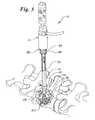
- FIG. 5is a perspective view of an embodiment of the invention as shown in its intended environment of use
- FIG. 6is an exploded view of an embodiment of the invention.
- FIG. 7is a detailed sectional view of portions of the housing of an embodiment of the invention.
- FIG. 8is a block diagram illustrating the use of an embodiment of the invention.
- the filler instrument 10has three primary portions: a central housing 12 , a tubular injection cylinder or needle 14 and a reservoir 16 .
- the needle 14defines a hollow needle chamber or passage 20 which includes a proximal opening 22 at proximal end 26 and a distal opening 24 at distal end 28 .
- the needle chamber 20has a diameter sufficient to allow passage of a bioceramic bead or other particle of material 40 to pass therethrough in a single-file line or individually.
- the needle passage 20 and openings 22 and 24will be approximately 0.5 mm to 5 mm in diameter.
- the proximal opening 22 of needle 14is in fluid communication with the reservoir 16 .
- the reservoirmay contain the fill material 40 such as bioceramic beads or other materials.
- the individual particles of material 40are sized to be able to enter the proximal opening on a one-at-a-time basis and pass through the passage 20 in a single file line when the device 10 is activated.
- the central housing 12defines a central passage or chamber 18 (as may best be seen in FIG. 6) through which the needle 14 may travel longitudinally therein.
- the proximal end 26extends proximally beyond the housing 12 and passage 18 and is engaged to the reservoir 16 .
- the reservoir 16is defined by a reservoir housing 32 .
- the reservoir housing 32is engaged to the proximal end 26 of the needle 14 by a mounting collar 30 .
- the mounting collar 30employs one or more fastening members 34 to retain the proximal end 26 of the needle 14 therein.
- the fastening members 34may be any type of fastener such as a screw, bolt, clip, etc.
- the mounting collar 30may be engaged to the reservoir housing 32 by any of a variety of mechanisms.
- the collar 30 and reservoir housing 32may be opposingly threaded to allow the collar to be screwed into the reservoir housing 32 , the collar 30 may be sized to fittingly engage the reservoir housing 32 , the collar 30 may snap-fit into the reservoir housing, etc.
- the collar 30includes an angled opening slot 42 .
- the slot 42is designed to allow beads to pass into the proximal opening 22 of the needle chamber 20 on a one-at-a-time basis such as is depicted in FIGS. 2 and 4.
- the unique configuration of the opening slot 42helps to prevent beads or other fill material from blocking the proximal opening 22 as well as prevent multiple beads or particles from plugging the needle chamber 20 .
- the present deviceprovides a user with a significant degree of control for placement of the beads in a delivery site, such as is illustrated in FIGS. 4-5.
- the reservoir housing 32defines a reservoir chamber 36 which may be filled in-whole or in-part by a predetermined number or volume of fill material 40 .
- the reservoir housing 32may be at least partially transparent to allow a user to see the material 40 within the reservoir chamber 36 .
- the reservoir housing 32may also include volume indicators or markings so that the volume of material 40 remaining within the chamber 36 may be readily determined at any time.
- the fill material 40may be comprised of bone graft material, bioceramic beads, crushed bone, and/or other types of biocompatible fill material.
- the reservoir housingalso includes a reservoir plug or seal 38 which may be readily removed from the reservoir housing 32 to allow the fill material 40 to be inserted therein, and may be engaged to the reservoir housing 32 to prevent spillage of the fill material 40 therefrom.
- the seal 38When secured to the reservoir housing 32 , the seal 38 also acts to prevent the introduction of contaminants into the reservoir housing 32 .
- the needle 14extends from the reservoir 16 into the passage 18 of the central housing 12 .
- a proximal valve assembly 50Prior to entering the passage 18 , the needle 14 passes through a proximal valve assembly 50 , which provides a sliding valve seal 55 between the needle 14 and central housing 12 .
- the proximal valve assemblymay comprise a nut, ring or other type of retaining member 52 which is secured to a proximal valve receiving member 54 of the housing 12 .
- the retaining member 52 and receiving member 54may be reversibly threaded to allow the retaining member 52 to be threaded onto the receiving member 54 , or they may be otherwise constructed to provide removable engagement therebetween.
- the retaining member 52includes an inner radial lip 58 which defines an opening through which needle 14 is passed.
- the radial lip 58provides a surface upon which an o-ring 56 may be positioned.
- the proximal seal assembly 50defines the proximal end of a piston chamber 60 .
- the piston chamberincludes a fluid entrance port 62 which is connected to a fluid line 64 and source 44 shown in FIG. 8 .
- the fluid sourcemay be hydraulic, pneumatic, or any other means for providing liquid or air based pressure into the chamber 60 .
- the piston chamber 60includes a piston member 66 which extends outward from the needle 14 to the inner wall 68 of the chamber 60 .
- the piston member 66may be integral with the needle 14 or may be a separate apparatus through which the needle 14 is passed through and sealed therein.
- the piston member 66includes a groove or notch 70 about its circumference 72 .
- the notch 70provides a space in which a piston o-ring 74 is placed.
- the piston o-ring 74extends beyond the piston member 66 to contact the wall 68 .
- the presence of the piston o-ring 74 between the piston member 66 and the wall 68effectively provides a second or distal sliding valve seal 75 between the needle 14 and the housing 12 .
- the housing 12defines a biasing chamber 80 .
- the biasing chamber 80contains a biasing member or return spring 82 which is biased against the piston member 66 and a distal retaining collar 84 .
- the distal retaining collar 84may include one or more retaining projections 88 which project outwardly therefrom.
- the retaining projections 88are received into a corresponding number of receiving channels 86 positioned in the housing 12 , as is shown in FIG. 1 .
- the arrangement of retaining projections 88 and receiving channels 86provides the device 10 with the capacity to readily remove the retaining collar 84 thereby providing access to the various components discussed above contained within the housing 12 .
- any variety of affixing meansmay be used to removably engage the distal retaining collar 84 to the housing 12 .
- Such meansmay include, but are not limited to, screws and appropriately positioned holes, snap fit engagement of the collar 84 and housing 12 , respectively reversed threads to allow the collar 84 to be threadingly received into the housing 12 , etc.
- the distal retaining collar 84includes a proximally extending stop 78 , shown in FIG. 6 .
- the stop 78is constructed and arranged to limit the distance the piston member 66 can move when subjected to fluid pressure as discussed.
- the area between the distal retaining collar 84 and the piston member 66defines the biasing chamber 80 .
- the biasing member 82is compressed. After the biasing member 82 has moved to its full extent and is stopped by stop 78 , the fluid pressure will continue to build until it is sufficient to break the seal of valve seals 55 and/or 75 , thereby momentarily releasing the built up fluid pressure within the piston chamber 60 .
- the biasing member 82When the pressure is released in this manner, the biasing member 82 has sufficient force to push the piston member 66 proximally to its original at rest position or until fluid pressure is sufficient to once again overcome the biasing force supplied to the piston member 66 from the biasing member 82 , subsequent to which the piston will again begin moving distally to repeat the cycle.
- the wall 68 of the housing 12includes a vent hole 90 which allows air to travel out of the biasing chamber 80 during compression of the biasing member 82 and back therein during its expansion.
- the movement of the needle and reservoirmay be varied depending on the rate which fluid is injected into the chamber 60 .
- the ratemay be selectively controlled by a pressure switch, toggle, button, knob, lever, or other controller device 48 connected to the device 10 and/or fluid source 44 , such as is illustrated in FIG. 8 .
- the controller 48is a foot pedal which is operatively engaged to the fluid source 44 or line 64 .
- reciprocation of the needle 14 and reservoir 16functions, in-part, to vibrate or agitate the reservoir 16 and the fill material 40 located therein.
- the vibration of the reservoir 16ensures that only individual particles of fill material 40 are accepted into the slot 42 and eventually the needle chamber 20 . If multiple particles somehow manage to enter the slot 42 simultaneously, or the slot 42 , and/or needle chamber 20 become jammed with particles of fill material 40 , the vibration of the reservoir 16 and needle 14 is sufficient to dislodge the particles and/or blockage.
- the cyclic movement of the device 10also provides the distal end of the needle 14 with a controlled tapping action which when applied to deposited fill material 40 compacts the fill material 40 without breaking or otherwise degrading the particles. As a result the fill material can be deposited loosely or extremely tight within the deposit site as desired.
- an adjustable depth guide 92may be disposed about the needle 14 , such as is shown in FIG. 5 .
- the depth guide 92is effectively a hollow tube or sheath through which the needle 14 passes.
- the needle 14does not contact the depth guide 92 .
- the depth guide 92may be in intermittent or constant contact with the needle 14 . If the device is constructed in such a manner that the depth guide 92 and needle 14 may be in contact with one another, or are in contact with one another, a biocompatible lubricant may be applied to the internal surface of the depth guide 92 to ensure minimalization of friction created by the contact between the moving needle 14 and depth guide 92 .
- depth guide 92may be adjustable to provide the operating surgeon or technician with the ability to set the length of the needle 14 which may enter into the operating site 96 during reciprocation of the needle 14 .
- the proximal end 98 of the depth guide 92is threadingly engaged to the distal retaining collar 84 or other portion of the housing 12 .
- the depth guide 92may be extended or retracted relative to the needle 14 .
- the depth guide 92may be slidingly or otherwise adjustably engaged to the housing 12 or a portion thereof.
- a contact member 100which is sized to engage the opening or area of tissue adjacent to the opening of the operation site 96 .
- the contact membermay be integral with the depth guide 92 or may be permanently or removably attached thereto by a snap-fit, threading, sliding, or any other suitable attachment means or methods.
- Contact member 100may be constructed from any material suitable for use in a surgical device. It is preferable however, that contact member 100 be constructed from one or more material which may have vibration absorbing properties such as rubber, silicon or other vibration dampening materials.
- sheath 92 as well as other portions of device 10may include, or be constructed at least partially from vibration absorbing materials.
- the shape and size of the contact member 100are such that the contact member may be placed against and supported by the tissue surrounding the opening of the operation site 96 .
- the contact member 100When placed about the operation site 96 in such a manner, the contact member 100 provides a stable point of reference which the operating surgeon may use to determine, adjust and set the depth, or potential depth, of the needle 14 into the operating site 96 .
- the depth of the needle 14 into the operation site 96may be established with accuracy.
- the tapping and compacting action of the reciprocating needle 14 against the fill material 40may be precisely controlled. Such control will allow an operator to control or avoid inadvertent fracture or other potential damage to the particles of fill material 40 .
- inadvertent contact with the tissue of the operating site 96may also be reduced.
Landscapes
- Health & Medical Sciences (AREA)
- Orthopedic Medicine & Surgery (AREA)
- Life Sciences & Earth Sciences (AREA)
- Neurology (AREA)
- Surgery (AREA)
- Heart & Thoracic Surgery (AREA)
- Engineering & Computer Science (AREA)
- Biomedical Technology (AREA)
- Nuclear Medicine, Radiotherapy & Molecular Imaging (AREA)
- Medical Informatics (AREA)
- Molecular Biology (AREA)
- Animal Behavior & Ethology (AREA)
- General Health & Medical Sciences (AREA)
- Public Health (AREA)
- Veterinary Medicine (AREA)
- Surgical Instruments (AREA)
- Prostheses (AREA)
Abstract
Description
Claims (20)
Priority Applications (1)
| Application Number | Priority Date | Filing Date | Title |
|---|---|---|---|
| US09/909,668US6620162B2 (en) | 2001-07-20 | 2001-07-20 | Device for inserting fill material particles into body cavities |
Applications Claiming Priority (1)
| Application Number | Priority Date | Filing Date | Title |
|---|---|---|---|
| US09/909,668US6620162B2 (en) | 2001-07-20 | 2001-07-20 | Device for inserting fill material particles into body cavities |
Publications (2)
| Publication Number | Publication Date |
|---|---|
| US20030018292A1 US20030018292A1 (en) | 2003-01-23 |
| US6620162B2true US6620162B2 (en) | 2003-09-16 |
Family
ID=25427631
Family Applications (1)
| Application Number | Title | Priority Date | Filing Date |
|---|---|---|---|
| US09/909,668Expired - LifetimeUS6620162B2 (en) | 2001-07-20 | 2001-07-20 | Device for inserting fill material particles into body cavities |
Country Status (1)
| Country | Link |
|---|---|
| US (1) | US6620162B2 (en) |
Cited By (64)
| Publication number | Priority date | Publication date | Assignee | Title |
|---|---|---|---|---|
| US20020010472A1 (en)* | 2000-06-30 | 2002-01-24 | Kuslich Stephen D. | Tool to direct bone replacement material |
| US20030083642A1 (en)* | 2001-11-01 | 2003-05-01 | Boyd Lawrence M. | Devices and methods for the restoration of a spinal disc |
| US20040024410A1 (en)* | 2002-08-02 | 2004-02-05 | Scimed Life Systems, Inc. | Media delivery device for bone structures |
| US20040068268A1 (en)* | 2001-11-01 | 2004-04-08 | Boyd Lawrence M. | Devices and methods for the restoration of a spinal disc |
| US20050021043A1 (en)* | 2002-10-04 | 2005-01-27 | Herbert Andre Jansen | Apparatus for digitizing intramedullary canal and method |
| US20050059979A1 (en)* | 2003-09-11 | 2005-03-17 | Duran Yetkinler | Use of vibration with orthopedic cements |
| US20050070914A1 (en)* | 2003-09-11 | 2005-03-31 | Constantz Brent R. | Use of vibration with polymeric bone cements |
| US20050131417A1 (en)* | 2003-08-22 | 2005-06-16 | Ahern James W. | Kit for treating bony defects |
| US20050261781A1 (en)* | 2004-04-15 | 2005-11-24 | Sennett Andrew R | Cement-directing orthopedic implants |
| US20050278023A1 (en)* | 2004-06-10 | 2005-12-15 | Zwirkoski Paul A | Method and apparatus for filling a cavity |
| US20060004326A1 (en)* | 2004-06-29 | 2006-01-05 | Keith Collins | Apparatus and kit for injecting a curable biomaterial into into an intervertebral space |
| US20060106461A1 (en)* | 2004-11-12 | 2006-05-18 | Embry Jill M | Implantable vertebral lift |
| US20060265077A1 (en)* | 2005-02-23 | 2006-11-23 | Zwirkoski Paul A | Spinal repair |
| US20060282042A1 (en)* | 2005-06-08 | 2006-12-14 | Sensors For Medicine And Science, Inc. | Insertion device and method |
| US20070093899A1 (en)* | 2005-09-28 | 2007-04-26 | Christof Dutoit | Apparatus and methods for treating bone |
| US20070233146A1 (en)* | 2006-01-27 | 2007-10-04 | Stryker Corporation | Low pressure delivery system and method for delivering a solid and liquid mixture into a target site for medical treatment |
| US20080071281A1 (en)* | 2006-09-08 | 2008-03-20 | Spine Wave Inc. | Modular Injection Needle and Seal Assembly |
| US20080113008A1 (en)* | 2006-09-14 | 2008-05-15 | Karen Roche | Absorbent fabric implant |
| US20080221572A1 (en)* | 2007-03-08 | 2008-09-11 | Aequos Endoprothetik Gmbh | Device for temporary fixation of parts of a human joint |
| US20090069850A1 (en)* | 2001-11-03 | 2009-03-12 | Sebastian Fuerderer | Device for straightening and stabilizing the vertebral column |
| US7520888B2 (en) | 2006-02-14 | 2009-04-21 | Warsaw Orthopedic, Inc. | Treatment of the vertebral column |
| US20090149860A1 (en)* | 2005-07-07 | 2009-06-11 | Scribner Robert M | Device for delivery of bone void filling materials |
| US7666205B2 (en) | 2001-04-19 | 2010-02-23 | Synthes Usa, Llc | Inflatable device and method for reducing fractures in bone and in treating the spine |
| WO2010078510A2 (en) | 2008-12-31 | 2010-07-08 | Spineology, Inc. | System and method for performing percutaneous spinal interbody fusion |
| US20100185290A1 (en)* | 2007-06-29 | 2010-07-22 | Curtis Compton | Flexible chain implants and instrumentation |
| US7811291B2 (en) | 2007-11-16 | 2010-10-12 | Osseon Therapeutics, Inc. | Closed vertebroplasty bone cement injection system |
| US20100262240A1 (en)* | 2007-11-16 | 2010-10-14 | Kris Chavatte | Porous containment device and associated method for stabilization of vertebral compression fractures |
| US20100262242A1 (en)* | 2009-04-09 | 2010-10-14 | Kris Chavatte | Minimally invasive spine augmentation and stabilization system and method |
| US7879103B2 (en) | 2005-04-15 | 2011-02-01 | Musculoskeletal Transplant Foundation | Vertebral disc repair |
| US20110054532A1 (en)* | 2007-07-03 | 2011-03-03 | Alexandre De Moura | Interspinous mesh |
| US7909873B2 (en) | 2006-12-15 | 2011-03-22 | Soteira, Inc. | Delivery apparatus and methods for vertebrostenting |
| US7959683B2 (en) | 2006-07-25 | 2011-06-14 | Musculoskeletal Transplant Foundation | Packed demineralized cancellous tissue forms for disc nucleus augmentation, restoration, or replacement and methods of implantation |
| US20110213402A1 (en)* | 2005-05-24 | 2011-09-01 | Kyphon Sarl | Low-compliance expandable medical device |
| US8118812B2 (en) | 2004-03-09 | 2012-02-21 | Skeletal Kinetics, Llc | Use of vibration in composite fixation |
| US8142462B2 (en) | 2004-05-28 | 2012-03-27 | Cavitech, Llc | Instruments and methods for reducing and stabilizing bone fractures |
| US20120116515A1 (en)* | 2010-10-25 | 2012-05-10 | Semler Eric J | Demineralized cortical bone implants |
| US8221420B2 (en) | 2009-02-16 | 2012-07-17 | Aoi Medical, Inc. | Trauma nail accumulator |
| US8353911B2 (en) | 2007-05-21 | 2013-01-15 | Aoi Medical, Inc. | Extendable cutting member |
| US8529628B2 (en) | 2009-06-17 | 2013-09-10 | Trinity Orthopedics, Llc | Expanding intervertebral device and methods of use |
| US8827981B2 (en) | 2007-11-16 | 2014-09-09 | Osseon Llc | Steerable vertebroplasty system with cavity creation element |
| US8828082B2 (en) | 2009-07-09 | 2014-09-09 | R Tree Innovations, Llc | Inter-body implant |
| US8951265B2 (en) | 2011-06-20 | 2015-02-10 | Rdc Holdings, Llc | Fixation system for orthopedic devices |
| US8998925B2 (en) | 2011-06-20 | 2015-04-07 | Rdc Holdings, Llc | Fixation system for orthopedic devices |
| US9084681B2 (en) | 2010-06-18 | 2015-07-21 | DePuy Synthes Products, Inc. | Spine disc replacement with compliant articulating core |
| US9192397B2 (en) | 2006-12-15 | 2015-11-24 | Gmedelaware 2 Llc | Devices and methods for fracture reduction |
| US9220554B2 (en) | 2010-02-18 | 2015-12-29 | Globus Medical, Inc. | Methods and apparatus for treating vertebral fractures |
| US9289240B2 (en) | 2005-12-23 | 2016-03-22 | DePuy Synthes Products, Inc. | Flexible elongated chain implant and method of supporting body tissue with same |
| US9326806B2 (en) | 2003-09-02 | 2016-05-03 | Crosstrees Medical, Inc. | Devices and methods for the treatment of bone fracture |
| US9480485B2 (en) | 2006-12-15 | 2016-11-01 | Globus Medical, Inc. | Devices and methods for vertebrostenting |
| US9510885B2 (en) | 2007-11-16 | 2016-12-06 | Osseon Llc | Steerable and curvable cavity creation system |
| US9539041B2 (en) | 2013-09-12 | 2017-01-10 | DePuy Synthes Products, Inc. | Minimally invasive biomaterial injection system |
| US9707024B2 (en) | 2004-03-09 | 2017-07-18 | Skeletal Kinetics, Llc | Use of vibration in composite fixation |
| US9980715B2 (en) | 2014-02-05 | 2018-05-29 | Trinity Orthopedics, Llc | Anchor devices and methods of use |
| US10441336B2 (en) | 2017-06-14 | 2019-10-15 | Osteoagra Llc | Stabilization of vertebral bodies with bone particle slurry |
| US10463380B2 (en) | 2016-12-09 | 2019-11-05 | Dfine, Inc. | Medical devices for treating hard tissues and related methods |
| US10478241B2 (en) | 2016-10-27 | 2019-11-19 | Merit Medical Systems, Inc. | Articulating osteotome with cement delivery channel |
| US10624652B2 (en) | 2010-04-29 | 2020-04-21 | Dfine, Inc. | System for use in treatment of vertebral fractures |
| US10660656B2 (en) | 2017-01-06 | 2020-05-26 | Dfine, Inc. | Osteotome with a distal portion for simultaneous advancement and articulation |
| US10932839B2 (en) | 2017-12-19 | 2021-03-02 | Stryker Corporation | Systems and methods for delivering elements within a fluent material to an off-axis target site within a bone structure |
| US11026744B2 (en) | 2016-11-28 | 2021-06-08 | Dfine, Inc. | Tumor ablation devices and related methods |
| US11197681B2 (en) | 2009-05-20 | 2021-12-14 | Merit Medical Systems, Inc. | Steerable curvable vertebroplasty drill |
| US11510723B2 (en) | 2018-11-08 | 2022-11-29 | Dfine, Inc. | Tumor ablation device and related systems and methods |
| US11986229B2 (en) | 2019-09-18 | 2024-05-21 | Merit Medical Systems, Inc. | Osteotome with inflatable portion and multiwire articulation |
| US12102367B2 (en) | 2017-06-14 | 2024-10-01 | Osteoagra Llc | Method, composition, and apparatus for stabilization of vertebral bodies |
Families Citing this family (5)
| Publication number | Priority date | Publication date | Assignee | Title |
|---|---|---|---|---|
| US20050113843A1 (en)* | 2003-11-25 | 2005-05-26 | Arramon Yves P. | Remotely actuated system for bone cement delivery |
| EP1786344B1 (en)* | 2004-09-10 | 2010-12-01 | Kieran P. Murphy | Cement delivery needle |
| US7988735B2 (en)* | 2005-06-15 | 2011-08-02 | Matthew Yurek | Mechanical apparatus and method for delivering materials into the inter-vertebral body space for nucleus replacement |
| US10285825B2 (en)* | 2016-04-07 | 2019-05-14 | Howmedica Osteonics Corp. | Surgical insertion instruments |
| EP3456297B1 (en) | 2017-09-15 | 2023-10-04 | Howmedica Osteonics Corp. | Instruments for expandable interbody implants |
Citations (11)
| Publication number | Priority date | Publication date | Assignee | Title |
|---|---|---|---|---|
| US834261A (en)* | 1906-04-04 | 1906-10-30 | Clarence S Chambers | Vaccine-injector. |
| US1347622A (en)* | 1919-03-29 | 1920-07-27 | Arthur E Deininger | Vaccine-injector |
| US2659369A (en)* | 1952-11-13 | 1953-11-17 | Michael G Lipman | Pellet implanter |
| DE1223495B (en) | 1956-08-24 | 1966-08-25 | Foundation Lab Inc | Device for subcutaneous implantation of hormone preparations u. Like. In animal bodies |
| FR2287894A1 (en) | 1974-10-15 | 1976-05-14 | Roussel Uclaf | Automatic pellet implanting device - for subcutaneous introduction of prods into animals |
| EP0621020A1 (en) | 1993-04-21 | 1994-10-26 | SULZER Medizinaltechnik AG | Intervertebral prosthesis and method of implanting such a prosthesis |
| DE4409836A1 (en) | 1994-03-22 | 1995-09-28 | Draenert Klaus | Device for the mechanical protection of an implant or graft when inserted into and / or remaining in a living body |
| US5549679A (en) | 1994-05-20 | 1996-08-27 | Kuslich; Stephen D. | Expandable fabric implant for stabilizing the spinal motion segment |
| US6171312B1 (en) | 1996-07-18 | 2001-01-09 | Implant Innovations, Inc. | Power-driven osteotome tools for compaction of bone tissue |
| US6340299B1 (en)* | 1999-04-21 | 2002-01-22 | Yoshiyuki Saito | Device for pouring dental mixture |
| US6387130B1 (en)* | 1999-04-16 | 2002-05-14 | Nuvasive, Inc. | Segmented linked intervertebral implant systems |
- 2001
- 2001-07-20USUS09/909,668patent/US6620162B2/ennot_activeExpired - Lifetime
Patent Citations (13)
| Publication number | Priority date | Publication date | Assignee | Title |
|---|---|---|---|---|
| US834261A (en)* | 1906-04-04 | 1906-10-30 | Clarence S Chambers | Vaccine-injector. |
| US1347622A (en)* | 1919-03-29 | 1920-07-27 | Arthur E Deininger | Vaccine-injector |
| US2659369A (en)* | 1952-11-13 | 1953-11-17 | Michael G Lipman | Pellet implanter |
| DE1223495B (en) | 1956-08-24 | 1966-08-25 | Foundation Lab Inc | Device for subcutaneous implantation of hormone preparations u. Like. In animal bodies |
| FR2287894A1 (en) | 1974-10-15 | 1976-05-14 | Roussel Uclaf | Automatic pellet implanting device - for subcutaneous introduction of prods into animals |
| US5702454A (en) | 1993-04-21 | 1997-12-30 | Sulzer Orthopadie Ag | Process for implanting an invertebral prosthesis |
| EP0621020A1 (en) | 1993-04-21 | 1994-10-26 | SULZER Medizinaltechnik AG | Intervertebral prosthesis and method of implanting such a prosthesis |
| DE4409836A1 (en) | 1994-03-22 | 1995-09-28 | Draenert Klaus | Device for the mechanical protection of an implant or graft when inserted into and / or remaining in a living body |
| US5549679A (en) | 1994-05-20 | 1996-08-27 | Kuslich; Stephen D. | Expandable fabric implant for stabilizing the spinal motion segment |
| US5571189A (en) | 1994-05-20 | 1996-11-05 | Kuslich; Stephen D. | Expandable fabric implant for stabilizing the spinal motion segment |
| US6171312B1 (en) | 1996-07-18 | 2001-01-09 | Implant Innovations, Inc. | Power-driven osteotome tools for compaction of bone tissue |
| US6387130B1 (en)* | 1999-04-16 | 2002-05-14 | Nuvasive, Inc. | Segmented linked intervertebral implant systems |
| US6340299B1 (en)* | 1999-04-21 | 2002-01-22 | Yoshiyuki Saito | Device for pouring dental mixture |
Non-Patent Citations (1)
| Title |
|---|
| U.S. patent application Ser. No. 60/256,014, Stephen Kuslich, filed Dec. 15, 2000. |
Cited By (128)
| Publication number | Priority date | Publication date | Assignee | Title |
|---|---|---|---|---|
| US20020010472A1 (en)* | 2000-06-30 | 2002-01-24 | Kuslich Stephen D. | Tool to direct bone replacement material |
| US7025771B2 (en)* | 2000-06-30 | 2006-04-11 | Spineology, Inc. | Tool to direct bone replacement material |
| US7666205B2 (en) | 2001-04-19 | 2010-02-23 | Synthes Usa, Llc | Inflatable device and method for reducing fractures in bone and in treating the spine |
| US7004945B2 (en)* | 2001-11-01 | 2006-02-28 | Spinewave, Inc. | Devices and methods for the restoration of a spinal disc |
| US20030083642A1 (en)* | 2001-11-01 | 2003-05-01 | Boyd Lawrence M. | Devices and methods for the restoration of a spinal disc |
| US20040068268A1 (en)* | 2001-11-01 | 2004-04-08 | Boyd Lawrence M. | Devices and methods for the restoration of a spinal disc |
| US7914537B2 (en) | 2001-11-01 | 2011-03-29 | Spine Wave, Inc. | Devices and methods for the restoration of a spinal disc |
| US7575577B2 (en)* | 2001-11-01 | 2009-08-18 | Spinewave | Devices and methods for the restoration of a spinal disc |
| US20090131946A1 (en)* | 2001-11-01 | 2009-05-21 | Spine Wave, Inc. | Devices and Methods for the Restoration of a Spinal Disc |
| US10357291B2 (en) | 2001-11-03 | 2019-07-23 | DePuy Synthes Products, Inc. | Device for straightening and stabilizing the vertebral column |
| US9295502B2 (en) | 2001-11-03 | 2016-03-29 | DePuy Synthes Products, Inc. | Device for straightening and stabilizing the vertebral column |
| US11051862B2 (en)* | 2001-11-03 | 2021-07-06 | DePuy Synthes Products, Inc. | Device for straightening and stabilizing the vertebral column |
| US20090069850A1 (en)* | 2001-11-03 | 2009-03-12 | Sebastian Fuerderer | Device for straightening and stabilizing the vertebral column |
| US8491591B2 (en) | 2001-11-03 | 2013-07-23 | DePuy Synthes Products, LLC | Device for straightening and stabilizing the vertebral column |
| US9861401B2 (en) | 2001-11-03 | 2018-01-09 | DePuy Synthes Products, Inc. | Device for straightening and stabilizing the vertebral column |
| US20190008566A1 (en)* | 2001-11-03 | 2019-01-10 | DePuy Synthes Products, Inc. | Device for straightening and stabilizing the vertebral column |
| US7901407B2 (en)* | 2002-08-02 | 2011-03-08 | Boston Scientific Scimed, Inc. | Media delivery device for bone structures |
| US20040024410A1 (en)* | 2002-08-02 | 2004-02-05 | Scimed Life Systems, Inc. | Media delivery device for bone structures |
| US20050021043A1 (en)* | 2002-10-04 | 2005-01-27 | Herbert Andre Jansen | Apparatus for digitizing intramedullary canal and method |
| US20050131417A1 (en)* | 2003-08-22 | 2005-06-16 | Ahern James W. | Kit for treating bony defects |
| US9326806B2 (en) | 2003-09-02 | 2016-05-03 | Crosstrees Medical, Inc. | Devices and methods for the treatment of bone fracture |
| US20050058717A1 (en)* | 2003-09-11 | 2005-03-17 | Duran Yetkinler | Methods and devices for delivering orthopedic cements to a target bone site |
| US8167889B2 (en) | 2003-09-11 | 2012-05-01 | Skeletal Kinectics, LLC | Use of vibration with orthopedic cements |
| US7261718B2 (en)* | 2003-09-11 | 2007-08-28 | Skeletal Kinetics Llc | Use of vibration with polymeric bone cements |
| US9833274B2 (en) | 2003-09-11 | 2017-12-05 | Skeletal Kinetics, Llc | Use of vibration with orthopedic cements |
| US7252672B2 (en)* | 2003-09-11 | 2007-08-07 | Skeletal Kinetics, Llc | Use of vibration with orthopedic cements |
| US20050059979A1 (en)* | 2003-09-11 | 2005-03-17 | Duran Yetkinler | Use of vibration with orthopedic cements |
| US20050070914A1 (en)* | 2003-09-11 | 2005-03-31 | Constantz Brent R. | Use of vibration with polymeric bone cements |
| US7261717B2 (en)* | 2003-09-11 | 2007-08-28 | Skeletal Kinetics Llc | Methods and devices for delivering orthopedic cements to a target bone site |
| US9707024B2 (en) | 2004-03-09 | 2017-07-18 | Skeletal Kinetics, Llc | Use of vibration in composite fixation |
| US8118812B2 (en) | 2004-03-09 | 2012-02-21 | Skeletal Kinetics, Llc | Use of vibration in composite fixation |
| US20050261781A1 (en)* | 2004-04-15 | 2005-11-24 | Sennett Andrew R | Cement-directing orthopedic implants |
| US7465318B2 (en) | 2004-04-15 | 2008-12-16 | Soteira, Inc. | Cement-directing orthopedic implants |
| US8100973B2 (en) | 2004-04-15 | 2012-01-24 | Soteira, Inc. | Cement-directing orthopedic implants |
| US8142462B2 (en) | 2004-05-28 | 2012-03-27 | Cavitech, Llc | Instruments and methods for reducing and stabilizing bone fractures |
| US8562634B2 (en) | 2004-05-28 | 2013-10-22 | Cavitech, Llc | Instruments and methods for reducing and stabilizing bone fractures |
| US20050278023A1 (en)* | 2004-06-10 | 2005-12-15 | Zwirkoski Paul A | Method and apparatus for filling a cavity |
| US9526539B2 (en) | 2004-06-10 | 2016-12-27 | Spinal Ventures, Llc | Non-soft tissue repair |
| WO2005122956A3 (en)* | 2004-06-10 | 2006-06-01 | Spinal Ventures | Method and apparatus for filling a cavity |
| US8734520B2 (en) | 2004-06-10 | 2014-05-27 | Spinal Ventures, Llc | Device and method for securing a fastener |
| US7682400B2 (en) | 2004-06-10 | 2010-03-23 | Spinal Ventures, Llc | Non-soft tissue repair |
| US20060004326A1 (en)* | 2004-06-29 | 2006-01-05 | Keith Collins | Apparatus and kit for injecting a curable biomaterial into into an intervertebral space |
| US8337557B2 (en)* | 2004-06-29 | 2012-12-25 | Spine Wave, Inc. | Apparatus and kit for injecting a curable biomaterial into an intervertebral space |
| US20060106461A1 (en)* | 2004-11-12 | 2006-05-18 | Embry Jill M | Implantable vertebral lift |
| US7799078B2 (en)* | 2004-11-12 | 2010-09-21 | Warsaw Orthopedic, Inc. | Implantable vertebral lift |
| US20060265077A1 (en)* | 2005-02-23 | 2006-11-23 | Zwirkoski Paul A | Spinal repair |
| US7879103B2 (en) | 2005-04-15 | 2011-02-01 | Musculoskeletal Transplant Foundation | Vertebral disc repair |
| US20110213402A1 (en)* | 2005-05-24 | 2011-09-01 | Kyphon Sarl | Low-compliance expandable medical device |
| US20060282042A1 (en)* | 2005-06-08 | 2006-12-14 | Sensors For Medicine And Science, Inc. | Insertion device and method |
| US9241660B2 (en) | 2005-06-08 | 2016-01-26 | Senseonics, Incorporated | Insertion device and method |
| US20090149860A1 (en)* | 2005-07-07 | 2009-06-11 | Scribner Robert M | Device for delivery of bone void filling materials |
| US20070093899A1 (en)* | 2005-09-28 | 2007-04-26 | Christof Dutoit | Apparatus and methods for treating bone |
| US11406508B2 (en) | 2005-12-23 | 2022-08-09 | DePuy Synthes Products, Inc. | Flexible elongated chain implant and method of supporting body tissue with same |
| US9956085B2 (en) | 2005-12-23 | 2018-05-01 | DePuy Synthes Products, Inc. | Flexible elongated chain implant and method of supporting body tissue with same |
| US11701233B2 (en) | 2005-12-23 | 2023-07-18 | DePuy Synthes Products, Inc. | Flexible elongated chain implant and method of supporting body tissue with same |
| US10881520B2 (en) | 2005-12-23 | 2021-01-05 | DePuy Synthes Products, Inc. | Flexible elongated chain implant and method of supporting body tissue with same |
| US9289240B2 (en) | 2005-12-23 | 2016-03-22 | DePuy Synthes Products, Inc. | Flexible elongated chain implant and method of supporting body tissue with same |
| US20160175019A1 (en)* | 2006-01-27 | 2016-06-23 | Stryker Corporation | Method Of Delivering A Plurality Of Elements And Fluent Material Into A Vertebral Body |
| US10426536B2 (en)* | 2006-01-27 | 2019-10-01 | Stryker Corporation | Method of delivering a plurality of elements and fluent material into a vertebral body |
| US20070233146A1 (en)* | 2006-01-27 | 2007-10-04 | Stryker Corporation | Low pressure delivery system and method for delivering a solid and liquid mixture into a target site for medical treatment |
| US9301792B2 (en) | 2006-01-27 | 2016-04-05 | Stryker Corporation | Low pressure delivery system and method for delivering a solid and liquid mixture into a target site for medical treatment |
| US7520888B2 (en) | 2006-02-14 | 2009-04-21 | Warsaw Orthopedic, Inc. | Treatment of the vertebral column |
| US8163018B2 (en) | 2006-02-14 | 2012-04-24 | Warsaw Orthopedic, Inc. | Treatment of the vertebral column |
| US7959683B2 (en) | 2006-07-25 | 2011-06-14 | Musculoskeletal Transplant Foundation | Packed demineralized cancellous tissue forms for disc nucleus augmentation, restoration, or replacement and methods of implantation |
| US8357168B2 (en)* | 2006-09-08 | 2013-01-22 | Spine Wave, Inc. | Modular injection needle and seal assembly |
| US20080071281A1 (en)* | 2006-09-08 | 2008-03-20 | Spine Wave Inc. | Modular Injection Needle and Seal Assembly |
| US20080113008A1 (en)* | 2006-09-14 | 2008-05-15 | Karen Roche | Absorbent fabric implant |
| US8623025B2 (en) | 2006-12-15 | 2014-01-07 | Gmedelaware 2 Llc | Delivery apparatus and methods for vertebrostenting |
| US9192397B2 (en) | 2006-12-15 | 2015-11-24 | Gmedelaware 2 Llc | Devices and methods for fracture reduction |
| US9237916B2 (en) | 2006-12-15 | 2016-01-19 | Gmedeleware 2 Llc | Devices and methods for vertebrostenting |
| US9480485B2 (en) | 2006-12-15 | 2016-11-01 | Globus Medical, Inc. | Devices and methods for vertebrostenting |
| US7909873B2 (en) | 2006-12-15 | 2011-03-22 | Soteira, Inc. | Delivery apparatus and methods for vertebrostenting |
| US20080221572A1 (en)* | 2007-03-08 | 2008-09-11 | Aequos Endoprothetik Gmbh | Device for temporary fixation of parts of a human joint |
| US8353911B2 (en) | 2007-05-21 | 2013-01-15 | Aoi Medical, Inc. | Extendable cutting member |
| US20100185290A1 (en)* | 2007-06-29 | 2010-07-22 | Curtis Compton | Flexible chain implants and instrumentation |
| US9907667B2 (en) | 2007-06-29 | 2018-03-06 | DePuy Synthes Products, Inc. | Flexible chain implants and instrumentation |
| US8673010B2 (en) | 2007-06-29 | 2014-03-18 | DePuy Synthes Products, LLC | Flexible chain implants and instrumentation |
| US12409043B2 (en) | 2007-06-29 | 2025-09-09 | DePuy Synthes Products, Inc. | Flexible chain implants and instrumentation |
| US10716679B2 (en) | 2007-06-29 | 2020-07-21 | DePuy Synthes Products, Inc. | Flexible chain implants and instrumentation |
| US8540752B2 (en) | 2007-07-03 | 2013-09-24 | Spine Tek, Inc. | Interspinous mesh |
| US20110054532A1 (en)* | 2007-07-03 | 2011-03-03 | Alexandre De Moura | Interspinous mesh |
| US8518115B2 (en) | 2007-11-16 | 2013-08-27 | DePuy Synthes Products, LLC | Porous containment device and associated method for stabilization of vertebral compression fractures |
| US9114019B2 (en) | 2007-11-16 | 2015-08-25 | DePuy Synthes Products, Inc. | Porous containment device and associated method for stabilization of vertebral compression fractures |
| US9510885B2 (en) | 2007-11-16 | 2016-12-06 | Osseon Llc | Steerable and curvable cavity creation system |
| US8827981B2 (en) | 2007-11-16 | 2014-09-09 | Osseon Llc | Steerable vertebroplasty system with cavity creation element |
| US20100262240A1 (en)* | 2007-11-16 | 2010-10-14 | Kris Chavatte | Porous containment device and associated method for stabilization of vertebral compression fractures |
| US7842041B2 (en) | 2007-11-16 | 2010-11-30 | Osseon Therapeutics, Inc. | Steerable vertebroplasty system |
| US7811291B2 (en) | 2007-11-16 | 2010-10-12 | Osseon Therapeutics, Inc. | Closed vertebroplasty bone cement injection system |
| US9687255B2 (en) | 2008-06-17 | 2017-06-27 | Globus Medical, Inc. | Device and methods for fracture reduction |
| US10588646B2 (en) | 2008-06-17 | 2020-03-17 | Globus Medical, Inc. | Devices and methods for fracture reduction |
| WO2010078510A2 (en) | 2008-12-31 | 2010-07-08 | Spineology, Inc. | System and method for performing percutaneous spinal interbody fusion |
| US8221420B2 (en) | 2009-02-16 | 2012-07-17 | Aoi Medical, Inc. | Trauma nail accumulator |
| US8911497B2 (en) | 2009-04-09 | 2014-12-16 | DePuy Synthes Products, LLC | Minimally invasive spine augmentation and stabilization system and method |
| US20100262242A1 (en)* | 2009-04-09 | 2010-10-14 | Kris Chavatte | Minimally invasive spine augmentation and stabilization system and method |
| US11197681B2 (en) | 2009-05-20 | 2021-12-14 | Merit Medical Systems, Inc. | Steerable curvable vertebroplasty drill |
| US8529628B2 (en) | 2009-06-17 | 2013-09-10 | Trinity Orthopedics, Llc | Expanding intervertebral device and methods of use |
| US8828082B2 (en) | 2009-07-09 | 2014-09-09 | R Tree Innovations, Llc | Inter-body implant |
| US9877844B2 (en) | 2009-07-09 | 2018-01-30 | R Tree Innovations, Llc | Inter-body implant |
| US9814599B2 (en) | 2009-07-09 | 2017-11-14 | R Tree Innovations, Llc | Inter-body implantation system and method |
| US10835386B2 (en) | 2009-07-09 | 2020-11-17 | R Tree Innovations, Llc | Inter-body implantation system and method |
| US10806594B2 (en) | 2009-07-09 | 2020-10-20 | R Tree Innovations, Llc | Inter-body implant |
| US9220554B2 (en) | 2010-02-18 | 2015-12-29 | Globus Medical, Inc. | Methods and apparatus for treating vertebral fractures |
| US10624652B2 (en) | 2010-04-29 | 2020-04-21 | Dfine, Inc. | System for use in treatment of vertebral fractures |
| US9084681B2 (en) | 2010-06-18 | 2015-07-21 | DePuy Synthes Products, Inc. | Spine disc replacement with compliant articulating core |
| US20120116515A1 (en)* | 2010-10-25 | 2012-05-10 | Semler Eric J | Demineralized cortical bone implants |
| US9687283B2 (en) | 2011-06-20 | 2017-06-27 | Rdc Holdings, Llc | Fixation system for orthopedic devices |
| US8951265B2 (en) | 2011-06-20 | 2015-02-10 | Rdc Holdings, Llc | Fixation system for orthopedic devices |
| US8998925B2 (en) | 2011-06-20 | 2015-04-07 | Rdc Holdings, Llc | Fixation system for orthopedic devices |
| US10660762B2 (en) | 2013-09-12 | 2020-05-26 | DePuy Synthes Product, Inc. | Minimally invasive biomaterial injection system |
| US9539041B2 (en) | 2013-09-12 | 2017-01-10 | DePuy Synthes Products, Inc. | Minimally invasive biomaterial injection system |
| US9980715B2 (en) | 2014-02-05 | 2018-05-29 | Trinity Orthopedics, Llc | Anchor devices and methods of use |
| US11344350B2 (en) | 2016-10-27 | 2022-05-31 | Dfine, Inc. | Articulating osteotome with cement delivery channel and method of use |
| US10478241B2 (en) | 2016-10-27 | 2019-11-19 | Merit Medical Systems, Inc. | Articulating osteotome with cement delivery channel |
| US12433671B2 (en) | 2016-11-28 | 2025-10-07 | Dfine, Inc. | Tumor ablation devices and related methods |
| US11116570B2 (en) | 2016-11-28 | 2021-09-14 | Dfine, Inc. | Tumor ablation devices and related methods |
| US11026744B2 (en) | 2016-11-28 | 2021-06-08 | Dfine, Inc. | Tumor ablation devices and related methods |
| US12011215B2 (en) | 2016-11-28 | 2024-06-18 | Dfine, Inc. | Tumor ablation devices and related methods |
| US10463380B2 (en) | 2016-12-09 | 2019-11-05 | Dfine, Inc. | Medical devices for treating hard tissues and related methods |
| US10470781B2 (en) | 2016-12-09 | 2019-11-12 | Dfine, Inc. | Medical devices for treating hard tissues and related methods |
| US11540842B2 (en) | 2016-12-09 | 2023-01-03 | Dfine, Inc. | Medical devices for treating hard tissues and related methods |
| US10660656B2 (en) | 2017-01-06 | 2020-05-26 | Dfine, Inc. | Osteotome with a distal portion for simultaneous advancement and articulation |
| US11607230B2 (en) | 2017-01-06 | 2023-03-21 | Dfine, Inc. | Osteotome with a distal portion for simultaneous advancement and articulation |
| US12102367B2 (en) | 2017-06-14 | 2024-10-01 | Osteoagra Llc | Method, composition, and apparatus for stabilization of vertebral bodies |
| US10441336B2 (en) | 2017-06-14 | 2019-10-15 | Osteoagra Llc | Stabilization of vertebral bodies with bone particle slurry |
| US10932839B2 (en) | 2017-12-19 | 2021-03-02 | Stryker Corporation | Systems and methods for delivering elements within a fluent material to an off-axis target site within a bone structure |
| US11937864B2 (en) | 2018-11-08 | 2024-03-26 | Dfine, Inc. | Ablation systems with parameter-based modulation and related devices and methods |
| US11510723B2 (en) | 2018-11-08 | 2022-11-29 | Dfine, Inc. | Tumor ablation device and related systems and methods |
| US11986229B2 (en) | 2019-09-18 | 2024-05-21 | Merit Medical Systems, Inc. | Osteotome with inflatable portion and multiwire articulation |
Also Published As
| Publication number | Publication date |
|---|---|
| US20030018292A1 (en) | 2003-01-23 |
Similar Documents
| Publication | Publication Date | Title |
|---|---|---|
| US6620162B2 (en) | Device for inserting fill material particles into body cavities | |
| WO2003007854A1 (en) | Device for inserting fill material particles into body cavities | |
| AU773220C (en) | Tools for injecting bone graft material | |
| US12167971B2 (en) | Bone graft delivery devices, systems and kits | |
| US12053393B2 (en) | Bone graft delivery system and method for use | |
| US8357169B2 (en) | System and method for delivering an agglomeration of solid beads and cement to the interior of a bone in order to form an implant within the bone | |
| US11160594B2 (en) | Bone cement applicator with a closable gas supply opening | |
| CN102232882B (en) | bone cement delivery device | |
| US12186205B2 (en) | Bone graft delivery systems and methods for using same | |
| US10245159B1 (en) | Bone graft delivery system and method for using same | |
| US20220304824A1 (en) | Bone graft delivery system and method for using same | |
| EP2029038B1 (en) | System for delivering an agglomeration of solid beads and cement to the interior of a bone in order to form an implant within the bone | |
| US9579137B2 (en) | Graft delivery system and methods thereof | |
| US20250134570A1 (en) | Method, composition, and apparatus for stabilization of vertebral bodies | |
| HK1106995A1 (en) | Device for producing a hardenable mass | |
| HK1106995B (en) | Device for producing a hardenable mass |
Legal Events
| Date | Code | Title | Description |
|---|---|---|---|
| AS | Assignment | Owner name:SPINEOLOGY GROUP LLC, THE, MINNESOTA Free format text:ASSIGNMENT OF ASSIGNORS INTEREST;ASSIGNORS:KUSLICH, STEPHEN D.;PETERSON, FRANCIS;GLEASON, JOSEPH E.;REEL/FRAME:012443/0738;SIGNING DATES FROM 20010727 TO 20010807 | |
| AS | Assignment | Owner name:SPINEOLOGY GROUP, LLC, THE, MINNESOTA Free format text:ASSIGNMENT OF ASSIGNORS INTEREST;ASSIGNOR:KUSLICH, STEPHEN;REEL/FRAME:012803/0260 Effective date:20000320 | |
| AS | Assignment | Owner name:SPINEOLOGY INC., MINNESOTA Free format text:CORRECTIVE ASSIGNMENT TO CORRECT ASSIGNEE RECORDED AT REEL 012803 FRAME 0260;ASSIGNOR:THE SPINEOLOGY GROUP LLC;REEL/FRAME:014301/0879 Effective date:20020320 | |
| STCF | Information on status: patent grant | Free format text:PATENTED CASE | |
| FEPP | Fee payment procedure | Free format text:PAYOR NUMBER ASSIGNED (ORIGINAL EVENT CODE: ASPN); ENTITY STATUS OF PATENT OWNER: SMALL ENTITY | |
| AS | Assignment | Owner name:MUSCULOSKELETAL TRANSPLANT FOUNDATION, INC., NEW J Free format text:SECURITY AGREEMENT;ASSIGNOR:SPINEOLOGY, INC.;REEL/FRAME:018563/0350 Effective date:20061130 | |
| AS | Assignment | Owner name:SPINEOLOGY, INC., MINNESOTA Free format text:MERGER;ASSIGNOR:SPINEOLOGY GROUP, LLC;REEL/FRAME:018668/0030 Effective date:20011130 | |
| FPAY | Fee payment | Year of fee payment:4 | |
| FPAY | Fee payment | Year of fee payment:8 | |
| AS | Assignment | Owner name:SPINEOLOGY, INC., MINNESOTA Free format text:RELEASE BY SECURED PARTY;ASSIGNOR:MUSCULOSKELETAL TRANSPLANT FOUNDATION, INC.;REEL/FRAME:027805/0445 Effective date:20120131 | |
| AS | Assignment | Owner name:VENTURE BANK, MINNESOTA Free format text:SECURITY AGREEMENT;ASSIGNOR:SPINEOLOGY INC.;REEL/FRAME:028550/0391 Effective date:20120706 | |
| AS | Assignment | Owner name:MUSCULOSKELETAL TRANSPLANT FOUNDATION, INC., NEW J Free format text:SECURITY AGREEMENT;ASSIGNOR:SPINEOLOGY INC;REEL/FRAME:030530/0491 Effective date:20130530 | |
| FPAY | Fee payment | Year of fee payment:12 | |
| AS | Assignment | Owner name:SPINEOLOGY INC., MINNESOTA Free format text:RELEASE BY SECURED PARTY;ASSIGNOR:VENTURE BANK;REEL/FRAME:038660/0458 Effective date:20160520 | |
| AS | Assignment | Owner name:JPMORGAN CHASE BANK, N.A., ILLINOIS Free format text:SECURITY INTEREST;ASSIGNOR:SPINEOLOGY INC.;REEL/FRAME:046514/0267 Effective date:20180727 | |
| AS | Assignment | Owner name:HORIZON TECHNOLOGY FINANCE CORPORATION, CONNECTICUT Free format text:SECURITY INTEREST;ASSIGNOR:SPINEOLOGY INC.;REEL/FRAME:057644/0286 Effective date:20210920 | |
| AS | Assignment | Owner name:SPINEOLOGY INC., MINNESOTA Free format text:RELEASE BY SECURED PARTY;ASSIGNOR:JPMORGAN CHASE BANK, N.A.;REEL/FRAME:065074/0545 Effective date:20230929 |