US6619719B1 - Tonneau cover with rotating rear rail and automatic tension control - Google Patents
Tonneau cover with rotating rear rail and automatic tension controlDownload PDFInfo
- Publication number
- US6619719B1 US6619719B1US10/150,376US15037602AUS6619719B1US 6619719 B1US6619719 B1US 6619719B1US 15037602 AUS15037602 AUS 15037602AUS 6619719 B1US6619719 B1US 6619719B1
- Authority
- US
- United States
- Prior art keywords
- rail
- connector assemblies
- side rails
- tonneau cover
- pair
- Prior art date
- Legal status (The legal status is an assumption and is not a legal conclusion. Google has not performed a legal analysis and makes no representation as to the accuracy of the status listed.)
- Expired - Lifetime
Links
Images


Classifications
- B—PERFORMING OPERATIONS; TRANSPORTING
- B60—VEHICLES IN GENERAL
- B60J—WINDOWS, WINDSCREENS, NON-FIXED ROOFS, DOORS, OR SIMILAR DEVICES FOR VEHICLES; REMOVABLE EXTERNAL PROTECTIVE COVERINGS SPECIALLY ADAPTED FOR VEHICLES
- B60J7/00—Non-fixed roofs; Roofs with movable panels, e.g. rotary sunroofs
- B60J7/08—Non-fixed roofs; Roofs with movable panels, e.g. rotary sunroofs of non-sliding type, i.e. movable or removable roofs or panels, e.g. let-down tops or roofs capable of being easily detached or of assuming a collapsed or inoperative position
- B60J7/085—Non-fixed roofs; Roofs with movable panels, e.g. rotary sunroofs of non-sliding type, i.e. movable or removable roofs or panels, e.g. let-down tops or roofs capable of being easily detached or of assuming a collapsed or inoperative position winding up, e.g. for utility vehicles
Definitions
- This inventionrelates to a tonneau cover and more particularly to a tonneau cover whose tautness is maintained without intervention by the user, and which allows simple access to the cargo area with a rotating rear rail.
- Tonneau coversare generally used to cover the cargo box of a vehicle, such as a pick-up truck.
- a typical tonneau coverincludes two primary components: a cover sheet made of fabric or other flexible, preferably waterproof, material; and a frame structure to which the perimeter of the cover sheet is removably attached and which is usually employed to removably position the cover sheet over the bed of a vehicle.
- the framegenerally comprises four rails: a left and a right side rail, which are removably affixed to each respective and opposed sidewall of a pick-up bed, and a front and a rear rail, which are respectively positioned near the passenger cab and the tailgate. Different rail configurations are possible for varying pickup bed configurations.
- the front and rear railsare usually connected to each of the side rails by connector assemblies which are generally manufactured from a material, such as, aluminum or plastic and which allow the rails to cooperatively and removably form a tonneau cover frame.
- Previous tonneau cover assembliestypically lack an easy and convenient means to remove the tonneau cover from a vehicle to gain access to the enclosed area. Complex user manipulation of the tonneau cover frame and cover was also typically required to place large objects into the cargo area or otherwise remove the rear rail of the tonneau cover frame.
- the known tonneau cover frame assembliesgenerally required user intervention to maintain the tonneau cover in a taut state during the lifetime of the tonneau cover. Stretching of the fabric cover due to seasonal temperature changes and daily thermal exposure, for example, causes the tonneau cover to expand and thus sag over the tonneau cover frame. User initiated tensioning of the tonneau cover would re-tension the cover to return it to its original taut state.
- the present inventionprovides a tonneau cover apparatus having a frame structure, a pair of springs and a flexible cover.
- the frame structurehas a pair of laterally spaced apart side rails, an end rail, and a pair of connector assemblies.
- Each of the connector assembliesis coupled to the end rail and movably mounted to an associated one of the side rails to moveably interconnect the end rail to the side rails.
- Each of the springsis coupled to one of the side rails and contacts an associated one of the connector assemblies.
- the flexible coveris removably attached to at least a portion of the frame structure. The springs bias the connector assemblies in a direction outward from the side rails and cause the end rail to apply a force to the flexible cover to maintain the flexible cover in a taut state.
- the tonneau cover of another preferred embodiment of the present inventionmounts to the cargo box of a vehicle.
- the tonneau coverincludes the frame of the tonneau cover and the cover that is removably attached to the frame.
- the frame of the tonneau coverincludes side rails, a rear rail, and a front rail, all of which are joined by connector assemblies.
- the framefurther includes a spring keeper assembly to maintain tautness of the tonneau cover.
- the front corner of tonneau cover framewhich is generally located just behind the cab of an open bed vehicle, includes the front rail, the associated side rail, and the front connector assembly, which comprise the front corner.
- the rear corner of the tonneau cover framewhich is generally located at the rear of the vehicle, includes the rear rail, the associated side rail, and the rear connector assembly.
- the spring keeperis generally found in the rear portion of the side rail and is connected to the rear connector assembly.
- the tonneau cover, the front rail, the rear rail, the side rails, associated connector assemblies, and the spring keeper assemblycomprise the tonneau cover system.
- the front connector assembliesare a single rigid perpendicular unit, while the rear connector assemblies are a two piece perpendicular unit that interlocks in such a way to provide a rotating corner.
- the front connector assemblies of the tonneau cover frametie the front rail to the associated side rails to form the front corners of the tonneau cover frame.
- the front connector assemblieswhen connected provide a rigid corner of the frame, but are easily removed by one person and without the use of tools.
- the rear connector assembliesare comprised of two pieces, one of which joins with the rear rail and the other with the associated side rail. The two piece design enables the user to conveniently detach the rear rail from the tonneau cover frame without having to disassemble and reassemble the rear connector assemblies.
- the rotating rear connector assembliesprovide for easy access to the cargo box, while providing a convenient means to open and close the tonneau cover.
- the two-piece connector assembliesunlock and detach from each other, allowing the user to roll the rear rail inside the tonneau cover toward the front of the vehicle.
- the useris able to detach the rear rail by use of the locking tabs and detents on the rear connector assemblies but needs to neither disassemble nor remove the rear connector assemblies to remove the rear rail.
- Closure of the tonneau coveris accomplished by inserting the rear rail and the associated rotating components of the rear connector assemblies back into the associated fixed components of the rear connector assemblies attached to the associated side rails. Closure causes the two piece rear connector assembly to latch and hold the rear rail in place, thereby returning the tonneau cover frame to its closed configuration.
- the spring keeper assemblyresides in the rear portion of the side rail and in direct engagement with the rear connector assembly.
- the spring keeperis comprised of housing, a spring, and a spring retaining device.
- the housingis secured in the rear rail in close proximity to the rear connector assembly, whereby the spring contained in the fixed housing can exert a force on the rear connector assembly.
- the force applied by the springforces the rear connector assembly to translate in a direction opposite the front connector assembly.
- the translation of the rear connector assemblyresults in the increase of the distance between the front rail and the rear rail thereby maintaining the tonneau cover in a taut state.
- the spring keeper assemblymaintains tautness of the tonneau cover without intervention by the user.
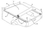
- FIG. 1is an environmental perspective view of a tonneau cover system constructed in accordance with the teachings of the present invention, with the tonneau cover shown in the closed position and attached to the cargo box of a vehicle;
- FIG. 2is an environmental perspective view of the tonneau cover system of FIG. 1 illustrating the tonneau cover in a partially rolled up condition;
- FIG. 3is a top plan view of a portion of the tonneau cover system in FIG. 1 illustrating the rear connector assembly components in a detached condition;
- FIG. 4is a top plan view similar to that of FIG. 3 but illustrating the rear connector assembly in an assembled condition
- FIG. 5is an exploded perspective view of a portion of the rear connector assembly of the tonneau cover system in FIG. 1;
- FIG. 6is a partial sectional view of a portion of the tonneau cover system of FIG. 1 illustrating the rear rail in rotated condition preparatory to engaging the rotatable component to the fixed component of the rear connector assembly;
- FIG. 7is a partial section view similar to FIG. 6 but illustrating the rotatable component partially engaged to fixed component
- FIG. 8is a partial section view similar to FIG. 6 but illustrating the rotatable component fully engaged to fixed component
- FIG. 9is a an exploded perspective view of a portion of the tonneau cover system of FIG. 1, but illustrating the spring keeper assembly in greater detail;
- FIG. 10is partial sectional view of a portion of the tonneau cover system of FIG. 1 illustrating the spring keeper assembly in an assembled condition in a side rail, similar to that of FIG. 1 .
- the tonneau cover system 8includes a frame structure 10 and a flexible tonneau cover 12 .
- the tonneau cover 12is closed and attached to the frame structure 10 .
- the frame structure 10includes a pair of side rails 14 , a front rail 16 , a rear rail 18 , front connector assemblies 20 , and rear connector assemblies 22 .
- the frame structure 10is attached to the cargo box 23 of a vehicle 24 .
- a vehicle 24Although the particular vehicle illustrated is a pick-up truck, those skilled in the art will appreciate that the tonneau cover system 8 may be used with other vehicles types and as such, the exemplary vehicle illustrated is not intended to limit the scope of the disclosure in any manner.
- the front rail 16may be optionally omitted from the frame structure 10 in an appropriate situation, as when the tonneau cover 12 is permanently affixed to the cargo box 23 .
- the tonneau cover 12is coupled to the frame structure 10 such that the frame structure 10 is positionable between a closed condition, which is illustrated in FIG. 1, and an open position, which is illustrated in FIG. 2 .
- the means by which the tonneau cover 12 is coupled to the frame structure 10is conventional, with one such means being described in U.S. Pat. No. 5,934,735 to Wheatley, which is incorporated by reference as if fully set forth herein.
- the tonneau cover 12is illustrated as being wrapped around the rear rail 18 .
- the tonneau cover 12detaches in a conventional manner from the associated side rail 14 as it is rolled, with one such means being described in U.S. Pat. No. 5,934,735 to Wheatley. As the tonneau cover 12 is rolled, it is wrapped about the rear rail 18 . The tonneau cover 12 remains attached to the rear rail 18 while it is rolled. Additional use of VELCRO® 27, or similar hook and loop type fasteners, prevents further axial movement of the rear rail 18 along its longitudinal axis.
- the rear rail 18is kept close to the fabric of tonneau cover 12 to ensure a small moment arm against which the fabric can pull while the user locks the rear rail 18 into the closed position.
- the rear connector assemblies 22are illustrated to include a fixed component 26 and a rotatable component 28 .
- Each fixed component 26is attached to an associated side rail 14 and remains fixed to the vehicle 24 .
- Each rotatable component 28is attached to the rear rail 18 and rotates when the tonneau cover 12 is opened.
- the rear connector assemblies 22are shown in greater detail in FIGS. 3 and 4.
- the fixed component 26 and the rotatable component 28 of the rear connector assembly 22are shown aligned but detached from one another.
- the fixed component 26includes a first plug end 44 , which includes a clip 33 and a detent 42 that accepts the locking tab 38 .
- the fixed component 26also includes a second end 29 that defines an aperture 30 , within which is formed a mating slot 32 .
- the first plug end 44 and the aperture 30are generally orthogonal to each other.
- the first plug end 44removably secures to the associated side rail 14 as shown in greater detail in FIG. 9 .
- First plug end 44is inserted into the associated side rail 14 and a clip 33 removably secures the fixed component 26 to the associated side rail 14 as in a manner that is disclosed in U.S. Pat. No. 5,934,735.
- the rotatable component 28includes a post end 34 , which includes a pawl 36 , a third plug end 46 and a clip 33 .
- the third plug end 46 and the post end 34are generally colinear.
- the rotatable component 28further includes a locking tab 38 .
- the locking tab 38is thin at its base 39 , or first end, to allow for easy flexing but thicker at the tip 41 , or second end, to aide in use.
- the locking tab 38has a rectangular cross-section where the base measures about 0.5 inches by about 0.06 inches, and the tip measures about 0.25 inches by about 0.12 inches.
- Reinforcement 40is assembled in locking engagement with the indentation 43 of the locking tab 38 to provide a constant force.
- the force upon the locking tab 38results in greater resiliency, thereby counteracting the possible loss in resiliency when the tonneau cover system components expand due to changes in ambient temperatures.
- the third plug end 46is fixedly but removably coupled to the rear rail 18 .
- Third plug end 46is inserted into rear rail 18 and clip 33 removably secures the rotatable component 28 to the rear rail 18 as in a manner disclosed in U.S. Pat. No. 5,934,735.
- the post end 34is removably disposed within aperture 30 ; as such, pawl 36 inserts into mating slot 32 as shown in greater detail in FIG. 5 .
- the rotatable component 28is rotated into locking engagement with the fixed component 26 , the progression of which is shown in greater detail in FIGS. 6, 7 , and 8 .
- the rear connector assembly 22is shown assembled such that the rotatable component 28 is secured to the fixed component 26 .
- Locking tab 38is shown in the open position and shown in phantom in a closed position, wherein the detent 42 has captured the locking tab 38 .
- the rear connector assembly 22is shown in a disassembled condition.
- the fixed component 26is shown with the mating slot 32 exposed along with the detent 42 .
- the detent 42accepts the locking tab 38
- the mating slot 32accepts the pawl 36 .
- the post end 34 of the rotatable component 28is inserted into the aperture 30 of the fixed component 26 , according to the progression shown in FIGS. 6, 7 , and 8 .
- FIGS. 6, 7 , and 8the progression of the rotatable component 28 is illustrated as it is locked into the fixed component 26 .
- the locking tab 38travels down a ramp 41 into the detent 42 .
- the depth of the detent 42is deep enough to capture the locking tab 38 , so that the rotatable component 28 is prevented from moving unless the locking tab 38 is released by the user.
- the front connector assemblies 20are conventional; as such, one example of their material and construction is described in U.S. Pat. No. 5,934,735.
- the rear connector assemblies 22are constructed of a plastic, but also could be constructed of metal or any other appropriate material. In the preferred embodiment of the present invention, the rear connector assemblies 22 are constructed of NYLON® or other similar polyamides.
- the front rail 16 , the rear rail 18 , and the pair of side rails 14are constructed of a metal, but also could be constructed of plastic, or any other appropriate material. In the preferred embodiment of the present invention, the front, rear, and pair of side rails 16 , 18 , 14 are constructed of extruded aluminum.
- the reinforcement 40 for locking tab 38is constructed of metal, but could be constructed of plastic or any other appropriate material according to one skilled in the art.
- the reinforcement 40is constructed of stainless steel with the thickness of about 0.02 inches and is in side-by-side locking engagement with the locking tab 38 .
- the spring keeper assembly 48is illustrated in association with a side rail 14 and a fixed component 26 .
- Side rail 14includes an opening 59 to accept the spring keeper assembly 48 and the fixed component 26 .
- Side rail 14also includes an elongated groove 56 , weather stripping 58 , and a bight 62 .
- Fixed component 26includes a first plug end 44 and a clip 33 .
- the spring keeper 48includes a spring 50 with coils 49 , a housing 52 with a threaded opening 53 and a spring retaining device 54 .
- the spring 50is contained within the housing 52 and held in place by the spring retaining device 54 , which in the particular embodiment illustrated, is a conventional threaded fastener that is threadably engaged to the housing 52 through the threaded opening 53 and disposed through the coils 49 of the spring 50 , as illustrated in FIG. 10 .
- the coils 49 of the spring 50are contained within the housing 52 .
- housing 52is inserted in the opening 59 of the associated side rail 14 , such that the threaded opening 53 aligns with the groove 56 .
- the spring retaining device 54is inserted through an elongated groove 56 and then through the threaded opening 53 .
- the spring retaining device 54is inserted into and held by the threaded opening 53 of housing 52 , thereby securing the housing 52 to the inside of the side rail 14 .
- Spring retaining device 54can be loosened to allow the spring keeper 48 to translate longitudinally in the associated side rail 14 .
- the end of the spring retaining device 54traps the coils 49 of spring 50 in the housing 52 , such that spring retaining device 54 is inserted through the elongated groove 56 , through the threaded opening 53 , and then through the coils 49 of the spring 50 .
- the housing 52has a closed end that traps the coils 49 of the spring 50 , such that the spring retaining device 54 does not protrude into the housing 52 and interfere in between the coils 49 of spring 50 .
- Weather stripping 58provides a seal between the tonneau cover and the lip of the cargo box (not shown). Bight 62 cooperates with the cylindrical fastening system of the tonneau cover (not shown), in a manner disclosed in U.S. Pat. No. 5,934,735.
- FIG. 10there is shown a sectional top view of the spring keeper assembly 48 assembled, an associated side rail 14 , and a fixed component 26 in accordance with the preferred embodiment of the present invention.
- the coils 49 of spring 50are shown in housing 52 .
- Spring retaining device 54is shown interdisposed between the coils 49 of the spring 50 .
- Fixed component 26includes the first plug end 44 inserted into the associated side rail 14 .
- the elongated groove 56is shown with the spring retaining device 54 inserted therein.
- Spring retaining device 54is shown inserted through the elongated groove 56 , wherein the spring retaining device 54 is in a full forward position within the elongated groove 56 .
- the full forward position of the housing 52 and spring retaining device 54correspond to the farthest position from the fixed component 26 .
- Different positions of the spring retaining device 54 and housing 52 in the elongated groove 56provide differing levels of force on the fixed component 26 .
- the force of the spring 50 applied to the first plug end 44pushes the fixed the component 26 outward from the associated side rail 14 , such that the distance will increase between the fixed component 26 and the associated side rail 14 .
- the rear rail 18is locked into the rear connector assembly 22 .
- the spring keeper assembly 48exerts a force on the first plug end 44 , thereby exerting a force on the rear connector assembly 22 .
- the rear rail 18 and rear connector assembly 22translate in a direction opposite the front rail 16 .
- the increase in distance between the rear rail 18 and the front rail 16increase the tautness on the tonneau cover 12 .
- the different positions of the spring keeper assembly 48 within the associated side rail 14are determined by the position of the spring retaining device 54 in the elongated groove 56 .
- differing positions of the spring retaining device 54will apply differing amounts of force on the first plug end 44 .
- Advancing the spring retaining device 54 full rearward in the elongated groove 56such that it is closer to the rear rail 18 , will apply the most force to the first plug end 44 .
- positioning the spring retaining device 54 in the full foreword position in the elongated groove 56such that the spring retaining device 54 is farthest from the rear rail 18 , will apply the least amount of force on the rear rail 18 .
- Proper positioning of the spring retaining device 54 within the elongated groove 56may be dictated by the age of the tonneau cover 12 (the tonneau cover may stretch) or, the ambient temperature to which the tonneau cover 12 is exposed. (Elevated ambient temperatures may cause the tonneau cover 12 to expand.) Positioning the spring retaining device 54 in the full rearward position for the greatest amount of force or the full foreword position for the least amount of force will maintain the tautness of the tonneau cover 12 depending on the amount of tautness control required.
Landscapes
- Engineering & Computer Science (AREA)
- Mechanical Engineering (AREA)
- Vehicle Step Arrangements And Article Storage (AREA)
Abstract
Description
Claims (22)
Priority Applications (1)
| Application Number | Priority Date | Filing Date | Title |
|---|---|---|---|
| US10/150,376US6619719B1 (en) | 2002-05-17 | 2002-05-17 | Tonneau cover with rotating rear rail and automatic tension control |
Applications Claiming Priority (1)
| Application Number | Priority Date | Filing Date | Title |
|---|---|---|---|
| US10/150,376US6619719B1 (en) | 2002-05-17 | 2002-05-17 | Tonneau cover with rotating rear rail and automatic tension control |
Publications (1)
| Publication Number | Publication Date |
|---|---|
| US6619719B1true US6619719B1 (en) | 2003-09-16 |
Family
ID=27804572
Family Applications (1)
| Application Number | Title | Priority Date | Filing Date |
|---|---|---|---|
| US10/150,376Expired - LifetimeUS6619719B1 (en) | 2002-05-17 | 2002-05-17 | Tonneau cover with rotating rear rail and automatic tension control |
Country Status (1)
| Country | Link |
|---|---|
| US (1) | US6619719B1 (en) |
Cited By (29)
| Publication number | Priority date | Publication date | Assignee | Title |
|---|---|---|---|---|
| US6719353B1 (en)* | 2003-05-29 | 2004-04-13 | Mark Isler | Roll up tonneau cover |
| US20040080177A1 (en)* | 2002-10-28 | 2004-04-29 | Cupelli Philip L. | Accessory attachment winder for installing, removing and storing a vehicle covering |
| US20040119314A1 (en)* | 2002-11-01 | 2004-06-24 | Brian Haack | Tonneau cover apparatus |
| US7008000B1 (en)* | 2003-10-31 | 2006-03-07 | Charles M. Schmeichel | Strap bracket for soft roll-up covers |
| US7147265B1 (en)* | 2005-12-07 | 2006-12-12 | Bismarck Canvas, Inc. | Collapsible truck bed cover |
| US7384090B1 (en)* | 2004-09-13 | 2008-06-10 | Advantage Truck Accessories, Inc. | Foldable tonneau cover |
| US20090322111A1 (en)* | 2008-06-30 | 2009-12-31 | Boomerang Enterprises, Inc. | Vehicle rack |
| US20100133872A1 (en)* | 2008-12-02 | 2010-06-03 | David Kosinski | Tensioner and fastening device for a tonneau cover |
| US20110169296A1 (en)* | 2010-01-13 | 2011-07-14 | Honda Motor Co., Ltd. | Tonneau cover assembly for a vehicle |
| US8973969B1 (en)* | 2012-12-06 | 2015-03-10 | Dennis Jay Potter | Tonneau cover system for vehicles |
| US20150069780A1 (en)* | 2012-07-21 | 2015-03-12 | Cixi City Liyuan Auto Parts Co., Ltd. | Compartment cover system for covering compartment of pickup truck |
| US9061572B2 (en) | 2013-10-11 | 2015-06-23 | Dennis Jay Potter | Perimeter seal for vehicle tonneau cover |
| US20150239388A1 (en)* | 2012-12-06 | 2015-08-27 | Dennis Jay Potter | Tonneau cover system for vehicles |
| US9254735B2 (en) | 2012-08-10 | 2016-02-09 | Truxedo, Inc. | Tonneau cover latch system |
| WO2016144321A1 (en)* | 2015-03-09 | 2016-09-15 | Potter Dennis Jay | Tonneau cover system for vehicles |
| US9776562B2 (en) | 2014-09-15 | 2017-10-03 | Rugged Liners, Inc. | Roll-up tonneau cover having a tensioning mechanism and a sideways latch |
| US9908391B2 (en) | 2014-09-15 | 2018-03-06 | Rugged Liner, Inc. | Adjustable tensioning mechanism for a soft roll up tonneau cover |
| US9914344B1 (en) | 2017-03-29 | 2018-03-13 | Honda Motor Co., Ltd. | Tonneau assemblies and methods of use and manufacture thereof |
| US9969249B2 (en) | 2016-09-20 | 2018-05-15 | Truxedo, Inc. | Tonneau cover system with side rail mounted latches and a rear header mounted release actuator |
| US10112465B2 (en)* | 2017-03-10 | 2018-10-30 | Richard Flocco | Vented tonneau cover for a cargo bed of a pickup truck |
| US10131215B2 (en) | 2017-03-29 | 2018-11-20 | Honda Motor Co., Ltd. | Flexible tonneau cover assembly |
| US10189339B2 (en) | 2016-07-27 | 2019-01-29 | Rugged Liner, Inc. | Tonneau cover system for a cargo bed of a vehicle |
| US10286765B2 (en) | 2016-10-28 | 2019-05-14 | Rugged Liner, Inc. | Tonneau cover system for a cargo bed of a vehicle |
| US10538150B2 (en) | 2017-03-29 | 2020-01-21 | Honda Motor Co., Ltd. | Flexible tonneau cover assembly |
| US10703181B2 (en) | 2017-01-06 | 2020-07-07 | Honda Motor Co., Ltd. | Tonneau assemblies and methods of use and manufacture thereof |
| US11427059B2 (en)* | 2018-08-02 | 2022-08-30 | Hang Shi | Soft tonneau cover with supporting cross bar |
| US11518223B2 (en) | 2018-12-12 | 2022-12-06 | Dennis Jay Potter | Tonneau system with stretchable cover |
| US11541736B2 (en)* | 2019-06-04 | 2023-01-03 | Fca Us Llc | Multiple position vehicle cover |
| US12428895B2 (en) | 2021-08-11 | 2025-09-30 | Magna Closures Inc. | Power-operated retractable closure panel for truck bed |
Citations (22)
| Publication number | Priority date | Publication date | Assignee | Title |
|---|---|---|---|---|
| US4144660A (en) | 1977-08-09 | 1979-03-20 | Art Products, Inc. | Adjustable stretching frame |
| US4302043A (en) | 1980-04-18 | 1981-11-24 | Wahpeton Canvas Company, Inc. | Roll-up tarp for trailers |
| USRE31746E (en) | 1980-04-18 | 1984-11-27 | Wahpeton Canvas Company, Inc. | Roll-up tarp for trailers |
| US4635700A (en)* | 1984-01-16 | 1987-01-13 | Berger Gustav A | Self-adjusting canvas tensioning frame |
| US5058652A (en) | 1984-09-14 | 1991-10-22 | Wheatley Donald G | Tonneau cover |
| US5076338A (en) | 1989-02-15 | 1991-12-31 | Agri-Cover, Inc. | Apparatus for covering an opening defined in a structure |
| US5121960A (en) | 1984-09-14 | 1992-06-16 | Wheatley Donald G | Rail attachment system for tonneau cover |
| US5174353A (en) | 1989-02-15 | 1992-12-29 | Agri-Cover, Inc. | Apparatus for covering an opening defined in a structure |
| US5251951A (en) | 1984-09-14 | 1993-10-12 | Wheatley Donald G | Tonneau cover and support means |
| US5288123A (en) | 1993-01-22 | 1994-02-22 | Wahpeton Canvas Co., South Dakota, Inc. | Bow cover |
| US5487584A (en) | 1993-03-12 | 1996-01-30 | Wahpeton Canvas Co. South Dakota, Inc. | Swing away support system for a covering |
| US5788315A (en) | 1996-06-03 | 1998-08-04 | Design Automotive Group, Inc. | Tonneau cover apparatus |
| US5906407A (en) | 1998-07-27 | 1999-05-25 | Schmeichel; Charles Milton | Tonneau cover tension adjuster apparatus |
| US5924758A (en) | 1997-07-10 | 1999-07-20 | Shur Company | Roll assist mechanism for tarp systems |
| US5934735A (en) | 1997-05-15 | 1999-08-10 | Wheatley; Donald G. | Connector assembly |
| US5938270A (en) | 1997-08-26 | 1999-08-17 | Shur Company | Quick release bow-to-cable connector for a covering system |
| US6024401A (en) | 1996-12-09 | 2000-02-15 | Wheatley; Donald G. | Tonneau cover with ball and socket rear rail latch |
| US6030021A (en)* | 1997-01-03 | 2000-02-29 | Ronai; Christian | Bed cover assembly for a vehicle bed |
| US6126226A (en)* | 1997-12-24 | 2000-10-03 | Wheatley; Donald G. | Tonneau assembly and a moisture drainage method for use with a tonneau assembly |
| US6257647B1 (en)* | 1998-01-16 | 2001-07-10 | Bestop, Inc. | Tonneau cover system |
| US6293608B1 (en)* | 2000-04-24 | 2001-09-25 | Penda Corporation | Self-adjusting tonneau cover assembly |
| US6309006B1 (en)* | 1999-10-21 | 2001-10-30 | Saddleman, Inc | Attachment system for truck beds |
- 2002
- 2002-05-17USUS10/150,376patent/US6619719B1/ennot_activeExpired - Lifetime
Patent Citations (22)
| Publication number | Priority date | Publication date | Assignee | Title |
|---|---|---|---|---|
| US4144660A (en) | 1977-08-09 | 1979-03-20 | Art Products, Inc. | Adjustable stretching frame |
| US4302043A (en) | 1980-04-18 | 1981-11-24 | Wahpeton Canvas Company, Inc. | Roll-up tarp for trailers |
| USRE31746E (en) | 1980-04-18 | 1984-11-27 | Wahpeton Canvas Company, Inc. | Roll-up tarp for trailers |
| US4635700A (en)* | 1984-01-16 | 1987-01-13 | Berger Gustav A | Self-adjusting canvas tensioning frame |
| US5058652A (en) | 1984-09-14 | 1991-10-22 | Wheatley Donald G | Tonneau cover |
| US5121960A (en) | 1984-09-14 | 1992-06-16 | Wheatley Donald G | Rail attachment system for tonneau cover |
| US5251951A (en) | 1984-09-14 | 1993-10-12 | Wheatley Donald G | Tonneau cover and support means |
| US5076338A (en) | 1989-02-15 | 1991-12-31 | Agri-Cover, Inc. | Apparatus for covering an opening defined in a structure |
| US5174353A (en) | 1989-02-15 | 1992-12-29 | Agri-Cover, Inc. | Apparatus for covering an opening defined in a structure |
| US5288123A (en) | 1993-01-22 | 1994-02-22 | Wahpeton Canvas Co., South Dakota, Inc. | Bow cover |
| US5487584A (en) | 1993-03-12 | 1996-01-30 | Wahpeton Canvas Co. South Dakota, Inc. | Swing away support system for a covering |
| US5788315A (en) | 1996-06-03 | 1998-08-04 | Design Automotive Group, Inc. | Tonneau cover apparatus |
| US6024401A (en) | 1996-12-09 | 2000-02-15 | Wheatley; Donald G. | Tonneau cover with ball and socket rear rail latch |
| US6030021A (en)* | 1997-01-03 | 2000-02-29 | Ronai; Christian | Bed cover assembly for a vehicle bed |
| US5934735A (en) | 1997-05-15 | 1999-08-10 | Wheatley; Donald G. | Connector assembly |
| US5924758A (en) | 1997-07-10 | 1999-07-20 | Shur Company | Roll assist mechanism for tarp systems |
| US5938270A (en) | 1997-08-26 | 1999-08-17 | Shur Company | Quick release bow-to-cable connector for a covering system |
| US6126226A (en)* | 1997-12-24 | 2000-10-03 | Wheatley; Donald G. | Tonneau assembly and a moisture drainage method for use with a tonneau assembly |
| US6257647B1 (en)* | 1998-01-16 | 2001-07-10 | Bestop, Inc. | Tonneau cover system |
| US5906407A (en) | 1998-07-27 | 1999-05-25 | Schmeichel; Charles Milton | Tonneau cover tension adjuster apparatus |
| US6309006B1 (en)* | 1999-10-21 | 2001-10-30 | Saddleman, Inc | Attachment system for truck beds |
| US6293608B1 (en)* | 2000-04-24 | 2001-09-25 | Penda Corporation | Self-adjusting tonneau cover assembly |
Non-Patent Citations (1)
| Title |
|---|
| Access Roll-Up Cover Owner's Manual; 1996 Agri-Cover, Inc. |
Cited By (34)
| Publication number | Priority date | Publication date | Assignee | Title |
|---|---|---|---|---|
| US20040080177A1 (en)* | 2002-10-28 | 2004-04-29 | Cupelli Philip L. | Accessory attachment winder for installing, removing and storing a vehicle covering |
| US6817650B2 (en)* | 2002-10-28 | 2004-11-16 | Philip L. Cupelli | Accessory attachment winder for installing, removing and storing a vehicle covering |
| US20040119314A1 (en)* | 2002-11-01 | 2004-06-24 | Brian Haack | Tonneau cover apparatus |
| US6948761B2 (en)* | 2002-11-01 | 2005-09-27 | The Colonel's International, Inc. | Tonneau cover apparatus |
| US6719353B1 (en)* | 2003-05-29 | 2004-04-13 | Mark Isler | Roll up tonneau cover |
| US7008000B1 (en)* | 2003-10-31 | 2006-03-07 | Charles M. Schmeichel | Strap bracket for soft roll-up covers |
| US7384090B1 (en)* | 2004-09-13 | 2008-06-10 | Advantage Truck Accessories, Inc. | Foldable tonneau cover |
| US7147265B1 (en)* | 2005-12-07 | 2006-12-12 | Bismarck Canvas, Inc. | Collapsible truck bed cover |
| US20090322111A1 (en)* | 2008-06-30 | 2009-12-31 | Boomerang Enterprises, Inc. | Vehicle rack |
| US20100133872A1 (en)* | 2008-12-02 | 2010-06-03 | David Kosinski | Tensioner and fastening device for a tonneau cover |
| US7954876B2 (en) | 2008-12-02 | 2011-06-07 | Rugged Liner | Tensioner and fastening device for a tonneau cover |
| US20110169296A1 (en)* | 2010-01-13 | 2011-07-14 | Honda Motor Co., Ltd. | Tonneau cover assembly for a vehicle |
| US8336946B2 (en) | 2010-01-13 | 2012-12-25 | Honda Motor Co., Ltd. | Tonneau cover assembly for a vehicle |
| US9067481B2 (en)* | 2012-07-21 | 2015-06-30 | Cixi City Liyuan Auto Parts Co., Ltd. | Compartment cover system for covering compartment of pickup truck |
| US20150069780A1 (en)* | 2012-07-21 | 2015-03-12 | Cixi City Liyuan Auto Parts Co., Ltd. | Compartment cover system for covering compartment of pickup truck |
| US9254735B2 (en) | 2012-08-10 | 2016-02-09 | Truxedo, Inc. | Tonneau cover latch system |
| US8973969B1 (en)* | 2012-12-06 | 2015-03-10 | Dennis Jay Potter | Tonneau cover system for vehicles |
| US20150239388A1 (en)* | 2012-12-06 | 2015-08-27 | Dennis Jay Potter | Tonneau cover system for vehicles |
| US9061572B2 (en) | 2013-10-11 | 2015-06-23 | Dennis Jay Potter | Perimeter seal for vehicle tonneau cover |
| US9776562B2 (en) | 2014-09-15 | 2017-10-03 | Rugged Liners, Inc. | Roll-up tonneau cover having a tensioning mechanism and a sideways latch |
| US9908391B2 (en) | 2014-09-15 | 2018-03-06 | Rugged Liner, Inc. | Adjustable tensioning mechanism for a soft roll up tonneau cover |
| WO2016144321A1 (en)* | 2015-03-09 | 2016-09-15 | Potter Dennis Jay | Tonneau cover system for vehicles |
| US10189339B2 (en) | 2016-07-27 | 2019-01-29 | Rugged Liner, Inc. | Tonneau cover system for a cargo bed of a vehicle |
| US9969249B2 (en) | 2016-09-20 | 2018-05-15 | Truxedo, Inc. | Tonneau cover system with side rail mounted latches and a rear header mounted release actuator |
| US10286765B2 (en) | 2016-10-28 | 2019-05-14 | Rugged Liner, Inc. | Tonneau cover system for a cargo bed of a vehicle |
| US10703181B2 (en) | 2017-01-06 | 2020-07-07 | Honda Motor Co., Ltd. | Tonneau assemblies and methods of use and manufacture thereof |
| US10112465B2 (en)* | 2017-03-10 | 2018-10-30 | Richard Flocco | Vented tonneau cover for a cargo bed of a pickup truck |
| US10131215B2 (en) | 2017-03-29 | 2018-11-20 | Honda Motor Co., Ltd. | Flexible tonneau cover assembly |
| US10538150B2 (en) | 2017-03-29 | 2020-01-21 | Honda Motor Co., Ltd. | Flexible tonneau cover assembly |
| US9914344B1 (en) | 2017-03-29 | 2018-03-13 | Honda Motor Co., Ltd. | Tonneau assemblies and methods of use and manufacture thereof |
| US11427059B2 (en)* | 2018-08-02 | 2022-08-30 | Hang Shi | Soft tonneau cover with supporting cross bar |
| US11518223B2 (en) | 2018-12-12 | 2022-12-06 | Dennis Jay Potter | Tonneau system with stretchable cover |
| US11541736B2 (en)* | 2019-06-04 | 2023-01-03 | Fca Us Llc | Multiple position vehicle cover |
| US12428895B2 (en) | 2021-08-11 | 2025-09-30 | Magna Closures Inc. | Power-operated retractable closure panel for truck bed |
Similar Documents
| Publication | Publication Date | Title |
|---|---|---|
| US6619719B1 (en) | Tonneau cover with rotating rear rail and automatic tension control | |
| US6024401A (en) | Tonneau cover with ball and socket rear rail latch | |
| US7484790B2 (en) | Covering structure having automatic coupling system | |
| US6808220B2 (en) | Tonneau cover adjustment mechanism | |
| US6811203B2 (en) | Roll up tonneau cover system | |
| US5303970A (en) | Overhead console for a vehicle with a sunroof | |
| US5251951A (en) | Tonneau cover and support means | |
| US6257647B1 (en) | Tonneau cover system | |
| US7954876B2 (en) | Tensioner and fastening device for a tonneau cover | |
| US20180111459A1 (en) | Truck cover system | |
| US20070024079A1 (en) | Covering structure having automatic coupling system | |
| US7204540B2 (en) | Method for covering structure having automatic coupling system | |
| US7216913B1 (en) | Hinged glove box door for motorcycles | |
| US6908096B2 (en) | Cover, including hinged door, for trailer hitch receivers of multiple sizes and methods | |
| US7165803B2 (en) | Tonneau cover | |
| US7150490B2 (en) | Tonneau cover | |
| US6874805B2 (en) | Cover with spring-biased door for trailer hitch receiver | |
| JPS6234821Y2 (en) | ||
| US7448667B2 (en) | Spring clip for use in a convertible top having side tension cables | |
| JPH0712228Y2 (en) | Automotive spoiler mounting structure | |
| JP2539268Y2 (en) | Convertible car roof side seal structure | |
| JPS6216096Y2 (en) | ||
| JP2868741B2 (en) | Lock handle device for non-rubbing engagement type door | |
| JPH0842229A (en) | Stay device with stop lever | |
| AU2005220256A1 (en) | Attachment Assembly for Clamping a Tonneau Cover to a Truck Bed |
Legal Events
| Date | Code | Title | Description |
|---|---|---|---|
| STCF | Information on status: patent grant | Free format text:PATENTED CASE | |
| FPAY | Fee payment | Year of fee payment:4 | |
| AS | Assignment | Owner name:EXTANG CORPORATION, MICHIGAN Free format text:ASSIGNMENT OF ASSIGNORS INTEREST;ASSIGNOR:WHEATLEY, DONALD G.;REEL/FRAME:020186/0196 Effective date:20071115 | |
| AS | Assignment | Owner name:MFC CAPITAL FUNDING, INC., AS AGENT, ILLINOIS Free format text:SECURITY AGREEMENT;ASSIGNOR:EXTANG CORPORATION;REEL/FRAME:020270/0218 Effective date:20071116 | |
| AS | Assignment | Owner name:EXTANG CORPORATION,MICHIGAN Free format text:TERMINATION AND RELEASE OF SECURITY INTEREST IN PATENTS RECORDED ON REEL/FRAME 020270/0218 ON 12/19/2007 AND REEL/FRAME 022542/0945 ON 4/15/2009;ASSIGNOR:MFC CAPITAL FUNDING, INC.;REEL/FRAME:024599/0459 Effective date:20100623 | |
| AS | Assignment | Owner name:MADISON CAPITAL FUNDING LLC, AS AGENT,ILLINOIS Free format text:SECURITY AGREEMENT;ASSIGNOR:EXTANG CORPORATION;REEL/FRAME:024626/0632 Effective date:20100623 Owner name:MADISON CAPITAL FUNDING LLC, AS AGENT, ILLINOIS Free format text:SECURITY AGREEMENT;ASSIGNOR:EXTANG CORPORATION;REEL/FRAME:024626/0632 Effective date:20100623 | |
| FPAY | Fee payment | Year of fee payment:8 | |
| AS | Assignment | Owner name:AMERICAN CAPITAL, LTD., MARYLAND Free format text:SECURITY INTEREST;ASSIGNOR:EXTANG CORPORATION;REEL/FRAME:032479/0900 Effective date:20140312 | |
| AS | Assignment | Owner name:AMERICAN CAPITAL, LTD., AS ADMINISTRATIVE AGENT, M Free format text:PATENT SECURITY AGREEMENT;ASSIGNOR:EXTANG CORPORATION;REEL/FRAME:033429/0668 Effective date:20140728 Owner name:EXTANG CORPORATION, MICHIGAN Free format text:RELEASE OF PATENT SECURITY AGREEMENT FILED 3/19/2014 AT REEL/FRAME: 032479/0900;ASSIGNOR:AMERICAN CAPITAL, LTD.;REEL/FRAME:033428/0957 Effective date:20140728 Owner name:EXTANG CORPORATION, MICHIGAN Free format text:RELEASE OF PATENT SECURITY AGREEMENT FILED 7/1/2010 AT REEL/FRAME: 024626/0632;ASSIGNOR:MADISON CAPITAL FUNDING LLC;REEL/FRAME:033429/0543 Effective date:20140728 Owner name:ARES CAPITAL CORPORATION, AS ADMINISTRATIVE AGENT, Free format text:PATENT SECURITY AGREEMENT;ASSIGNOR:EXTANG CORPORATION;REEL/FRAME:033429/0262 Effective date:20140728 | |
| FEPP | Fee payment procedure | Free format text:PAT HOLDER NO LONGER CLAIMS SMALL ENTITY STATUS, ENTITY STATUS SET TO UNDISCOUNTED (ORIGINAL EVENT CODE: STOL); ENTITY STATUS OF PATENT OWNER: LARGE ENTITY Free format text:PATENT HOLDER CLAIMS MICRO ENTITY STATUS, ENTITY STATUS SET TO MICRO (ORIGINAL EVENT CODE: STOM); ENTITY STATUS OF PATENT OWNER: LARGE ENTITY | |
| FPAY | Fee payment | Year of fee payment:12 | |
| AS | Assignment | Owner name:EXTANG CORPORATION, MICHIGAN Free format text:RELEASE BY SECURED PARTY;ASSIGNOR:MADISON CAPITAL FUNDING LLC, AS AGENT;REEL/FRAME:039807/0268 Effective date:20140728 | |
| AS | Assignment | Owner name:EXTANG CORPORATION, MICHIGAN Free format text:TERMINATION AND RELEASE OF GRANT OF SECURITY INTEREST IN TRADEMARK AND PATENT RIGHTS;ASSIGNOR:ARES CAPITAL CORPORATION, AS ADMINISTRATIVE AGENT;REEL/FRAME:039825/0484 Effective date:20160824 | |
| AS | Assignment | Owner name:JPMORGAN CHASE BANK, N.A., AS COLLATERAL AGENT, IL Free format text:FIRST LIEN PATENT SECURITY AGREEMENT;ASSIGNORS:EXTANG CORPORATION;TRUXEDO, INC.;BEDRUG, INC.;AND OTHERS;REEL/FRAME:039843/0220 Effective date:20160824 | |
| AS | Assignment | Owner name:JEFFERIES FINANCE LLC, AS ADMINISTRATIVE AND COLLA Free format text:PATENT SECURITY AGREEMENT (FIRST LIEN);ASSIGNOR:EXTANG CORPORATION;REEL/FRAME:042481/0488 Effective date:20170421 | |
| AS | Assignment | Owner name:JEFFERIES FINANCE LLC, AS ADMINISTRATIVE AND COLLA Free format text:PATENT SECURITY AGREEMENT (SECOND LIEN);ASSIGNOR:EXTANG CORPORATION;REEL/FRAME:042499/0346 Effective date:20170421 | |
| AS | Assignment | Owner name:ADVANTAGE TRUCK ACCESSORIES INC., MICHIGAN Free format text:TERMINATION AND RELEASE OF FIRST LIEN SECURITY INTEREST IN PATENTS AT REEL/FRAME NO. 039843/0220;ASSIGNOR:JPMORGAN CHASE BANK, N.A.;REEL/FRAME:042512/0749 Effective date:20170421 Owner name:EXTANG CORPORATION, MICHIGAN Free format text:TERMINATION AND RELEASE OF FIRST LIEN SECURITY INTEREST IN PATENTS AT REEL/FRAME NO. 039843/0220;ASSIGNOR:JPMORGAN CHASE BANK, N.A.;REEL/FRAME:042512/0749 Effective date:20170421 Owner name:BEDRUG, INC., TENNESSEE Free format text:TERMINATION AND RELEASE OF FIRST LIEN SECURITY INTEREST IN PATENTS AT REEL/FRAME NO. 039843/0220;ASSIGNOR:JPMORGAN CHASE BANK, N.A.;REEL/FRAME:042512/0749 Effective date:20170421 Owner name:TRUXEDO INC., SOUTH DAKOTA Free format text:TERMINATION AND RELEASE OF FIRST LIEN SECURITY INTEREST IN PATENTS AT REEL/FRAME NO. 039843/0220;ASSIGNOR:JPMORGAN CHASE BANK, N.A.;REEL/FRAME:042512/0749 Effective date:20170421 Owner name:EXTANG CORPORATION, MICHIGAN Free format text:TERMINATION AND RELEASE OF SECOND LIEN SECURITY INTEREST IN PATENT RIGHTS AT REEL/FRAME NO. 033429/0668;ASSIGNOR:ACAS, LLC (F/K/A AMERICAN CAPITAL, LTD.);REEL/FRAME:042512/0771 Effective date:20170421 Owner name:LAURMARK ENTERPRISES, INC., CALIFORNIA Free format text:TERMINATION AND RELEASE OF FIRST LIEN SECURITY INTEREST IN PATENTS AT REEL/FRAME NO. 039843/0220;ASSIGNOR:JPMORGAN CHASE BANK, N.A.;REEL/FRAME:042512/0749 Effective date:20170421 Owner name:A.R.E. ACCESSORIES LLC, OHIO Free format text:TERMINATION AND RELEASE OF FIRST LIEN SECURITY INTEREST IN PATENTS AT REEL/FRAME NO. 039843/0220;ASSIGNOR:JPMORGAN CHASE BANK, N.A.;REEL/FRAME:042512/0749 Effective date:20170421 Owner name:RETRAX HOLDINGS, LLC, NORTH DAKOTA Free format text:TERMINATION AND RELEASE OF FIRST LIEN SECURITY INTEREST IN PATENTS AT REEL/FRAME NO. 039843/0220;ASSIGNOR:JPMORGAN CHASE BANK, N.A.;REEL/FRAME:042512/0749 Effective date:20170421 Owner name:N-FAB, INC., TEXAS Free format text:TERMINATION AND RELEASE OF FIRST LIEN SECURITY INTEREST IN PATENTS AT REEL/FRAME NO. 039843/0220;ASSIGNOR:JPMORGAN CHASE BANK, N.A.;REEL/FRAME:042512/0749 Effective date:20170421 Owner name:UNDERCOVER, INC., MISSOURI Free format text:TERMINATION AND RELEASE OF FIRST LIEN SECURITY INTEREST IN PATENTS AT REEL/FRAME NO. 039843/0220;ASSIGNOR:JPMORGAN CHASE BANK, N.A.;REEL/FRAME:042512/0749 Effective date:20170421 | |
| AS | Assignment | Owner name:WILMINGTON TRUST, NATIONAL ASSOCIATION, AS COLLATE Free format text:PATENT SECURITY AGREEMENT (INDENTURE);ASSIGNOR:EXTANG CORPORATION;REEL/FRAME:049673/0083 Effective date:20190510 | |
| AS | Assignment | Owner name:BANK OF AMERICA, N.A., AS COLLATERAL AGENT, TEXAS Free format text:PATENT SECURITY AGREEMENT (ABL);ASSIGNOR:EXTANG CORPORATION;REEL/FRAME:055175/0678 Effective date:20210129 Owner name:JEFFERIES FINANCE LLC, AS COLLATERAL AGENT, NEW YORK Free format text:PATENT SECURITY AGREEMENT (TL);ASSIGNOR:EXTANG CORPORATION;REEL/FRAME:055270/0428 Effective date:20210129 | |
| AS | Assignment | Owner name:EXTANG CORPORATION, MICHIGAN Free format text:RELEASE BY SECURED PARTY;ASSIGNOR:JEFFERIES FINANCE LLC, AS ADMINISTRATIVE AND COLLATERAL AGENT;REEL/FRAME:055098/0521 Effective date:20210129 Owner name:EXTANG CORPORATION, MICHIGAN Free format text:RELEASE BY SECURED PARTY;ASSIGNOR:JEFFERIES FINANCE LLC, AS ADMINISTRATIVE AND COLLATERAL AGENT;REEL/FRAME:055098/0542 Effective date:20210129 | |
| AS | Assignment | Owner name:A.R.E. ACCESSORIES LLC, OHIO Free format text:RELEASE BY SECURED PARTY;ASSIGNOR:WILMINGTON TRUST, NATIONAL ASSOCIATION, AS COLLATERAL AGENT;REEL/FRAME:055193/0892 Effective date:20210129 Owner name:TRUXEDO INC., SOUTH DAKOTA Free format text:RELEASE BY SECURED PARTY;ASSIGNOR:WILMINGTON TRUST, NATIONAL ASSOCIATION, AS COLLATERAL AGENT;REEL/FRAME:055193/0892 Effective date:20210129 Owner name:RETRAX HOLDINGS, LLC, NORTH DAKOTA Free format text:RELEASE BY SECURED PARTY;ASSIGNOR:WILMINGTON TRUST, NATIONAL ASSOCIATION, AS COLLATERAL AGENT;REEL/FRAME:055193/0892 Effective date:20210129 Owner name:LAURMARK ENTERPRISES, INC., MICHIGAN Free format text:RELEASE BY SECURED PARTY;ASSIGNOR:WILMINGTON TRUST, NATIONAL ASSOCIATION, AS COLLATERAL AGENT;REEL/FRAME:055193/0892 Effective date:20210129 Owner name:LUND MOTION PRODUCTS, INC., GEORGIA Free format text:RELEASE BY SECURED PARTY;ASSIGNOR:WILMINGTON TRUST, NATIONAL ASSOCIATION, AS COLLATERAL AGENT;REEL/FRAME:055193/0892 Effective date:20210129 Owner name:OMIX-ADA, INC., GEORGIA Free format text:RELEASE BY SECURED PARTY;ASSIGNOR:WILMINGTON TRUST, NATIONAL ASSOCIATION, AS COLLATERAL AGENT;REEL/FRAME:055193/0892 Effective date:20210129 Owner name:N-FAB, INC., TEXAS Free format text:RELEASE BY SECURED PARTY;ASSIGNOR:WILMINGTON TRUST, NATIONAL ASSOCIATION, AS COLLATERAL AGENT;REEL/FRAME:055193/0892 Effective date:20210129 Owner name:EXTANG CORPORATION, MICHIGAN Free format text:RELEASE BY SECURED PARTY;ASSIGNOR:WILMINGTON TRUST, NATIONAL ASSOCIATION, AS COLLATERAL AGENT;REEL/FRAME:055193/0892 Effective date:20210129 Owner name:LUND, INC., GEORGIA Free format text:RELEASE BY SECURED PARTY;ASSIGNOR:WILMINGTON TRUST, NATIONAL ASSOCIATION, AS COLLATERAL AGENT;REEL/FRAME:055193/0892 Effective date:20210129 Owner name:ADVANTAGE TRUCK ACCESSORIES INC., MICHIGAN Free format text:RELEASE BY SECURED PARTY;ASSIGNOR:WILMINGTON TRUST, NATIONAL ASSOCIATION, AS COLLATERAL AGENT;REEL/FRAME:055193/0892 Effective date:20210129 Owner name:HUSKY LINERS, INC., KANSAS Free format text:RELEASE BY SECURED PARTY;ASSIGNOR:WILMINGTON TRUST, NATIONAL ASSOCIATION, AS COLLATERAL AGENT;REEL/FRAME:055193/0892 Effective date:20210129 Owner name:ROLL-N-LOCK CORPORATION, GEORGIA Free format text:RELEASE BY SECURED PARTY;ASSIGNOR:WILMINGTON TRUST, NATIONAL ASSOCIATION, AS COLLATERAL AGENT;REEL/FRAME:055193/0892 Effective date:20210129 Owner name:BUSHWACKER, INC., GEORGIA Free format text:RELEASE BY SECURED PARTY;ASSIGNOR:WILMINGTON TRUST, NATIONAL ASSOCIATION, AS COLLATERAL AGENT;REEL/FRAME:055193/0892 Effective date:20210129 Owner name:RUGGED LINER, INC., MICHIGAN Free format text:RELEASE BY SECURED PARTY;ASSIGNOR:WILMINGTON TRUST, NATIONAL ASSOCIATION, AS COLLATERAL AGENT;REEL/FRAME:055193/0892 Effective date:20210129 Owner name:UNDERCOVER, INC., MISSOURI Free format text:RELEASE BY SECURED PARTY;ASSIGNOR:WILMINGTON TRUST, NATIONAL ASSOCIATION, AS COLLATERAL AGENT;REEL/FRAME:055193/0892 Effective date:20210129 Owner name:BEDRUG, INC., TENNESSEE Free format text:RELEASE BY SECURED PARTY;ASSIGNOR:WILMINGTON TRUST, NATIONAL ASSOCIATION, AS COLLATERAL AGENT;REEL/FRAME:055193/0892 Effective date:20210129 |