US6619696B2 - Expandable locking thread joint - Google Patents
Expandable locking thread jointDownload PDFInfo
- Publication number
- US6619696B2 US6619696B2US10/010,866US1086601AUS6619696B2US 6619696 B2US6619696 B2US 6619696B2US 1086601 AUS1086601 AUS 1086601AUS 6619696 B2US6619696 B2US 6619696B2
- Authority
- US
- United States
- Prior art keywords
- pin
- box
- outer surfaces
- connection
- radial expansion
- Prior art date
- Legal status (The legal status is an assumption and is not a legal conclusion. Google has not performed a legal analysis and makes no representation as to the accuracy of the status listed.)
- Expired - Fee Related
Links
- 230000002706hydrostatic effectEffects0.000claimsabstractdescription7
- 238000004381surface treatmentMethods0.000claimsdescription25
- 238000003780insertionMethods0.000claimsdescription9
- 230000037431insertionEffects0.000claimsdescription9
- 229910003460diamondInorganic materials0.000claimsdescription2
- 239000010432diamondSubstances0.000claimsdescription2
- 239000000463materialSubstances0.000description2
- 239000002184metalSubstances0.000description2
- 238000012986modificationMethods0.000description1
- 230000004048modificationEffects0.000description1
Images


Classifications
- E—FIXED CONSTRUCTIONS
- E21—EARTH OR ROCK DRILLING; MINING
- E21B—EARTH OR ROCK DRILLING; OBTAINING OIL, GAS, WATER, SOLUBLE OR MELTABLE MATERIALS OR A SLURRY OF MINERALS FROM WELLS
- E21B43/00—Methods or apparatus for obtaining oil, gas, water, soluble or meltable materials or a slurry of minerals from wells
- E21B43/02—Subsoil filtering
- E21B43/10—Setting of casings, screens, liners or the like in wells
- E21B43/103—Setting of casings, screens, liners or the like in wells of expandable casings, screens, liners, or the like
- E21B43/106—Couplings or joints therefor
- C—CHEMISTRY; METALLURGY
- C23—COATING METALLIC MATERIAL; COATING MATERIAL WITH METALLIC MATERIAL; CHEMICAL SURFACE TREATMENT; DIFFUSION TREATMENT OF METALLIC MATERIAL; COATING BY VACUUM EVAPORATION, BY SPUTTERING, BY ION IMPLANTATION OR BY CHEMICAL VAPOUR DEPOSITION, IN GENERAL; INHIBITING CORROSION OF METALLIC MATERIAL OR INCRUSTATION IN GENERAL
- C23C—COATING METALLIC MATERIAL; COATING MATERIAL WITH METALLIC MATERIAL; SURFACE TREATMENT OF METALLIC MATERIAL BY DIFFUSION INTO THE SURFACE, BY CHEMICAL CONVERSION OR SUBSTITUTION; COATING BY VACUUM EVAPORATION, BY SPUTTERING, BY ION IMPLANTATION OR BY CHEMICAL VAPOUR DEPOSITION, IN GENERAL
- C23C8/00—Solid state diffusion of only non-metal elements into metallic material surfaces; Chemical surface treatment of metallic material by reaction of the surface with a reactive gas, leaving reaction products of surface material in the coating, e.g. conversion coatings, passivation of metals
- C23C8/06—Solid state diffusion of only non-metal elements into metallic material surfaces; Chemical surface treatment of metallic material by reaction of the surface with a reactive gas, leaving reaction products of surface material in the coating, e.g. conversion coatings, passivation of metals using gases
- C23C8/08—Solid state diffusion of only non-metal elements into metallic material surfaces; Chemical surface treatment of metallic material by reaction of the surface with a reactive gas, leaving reaction products of surface material in the coating, e.g. conversion coatings, passivation of metals using gases only one element being applied
- C23C8/24—Nitriding
- C23C8/26—Nitriding of ferrous surfaces
- C—CHEMISTRY; METALLURGY
- C23—COATING METALLIC MATERIAL; COATING MATERIAL WITH METALLIC MATERIAL; CHEMICAL SURFACE TREATMENT; DIFFUSION TREATMENT OF METALLIC MATERIAL; COATING BY VACUUM EVAPORATION, BY SPUTTERING, BY ION IMPLANTATION OR BY CHEMICAL VAPOUR DEPOSITION, IN GENERAL; INHIBITING CORROSION OF METALLIC MATERIAL OR INCRUSTATION IN GENERAL
- C23C—COATING METALLIC MATERIAL; COATING MATERIAL WITH METALLIC MATERIAL; SURFACE TREATMENT OF METALLIC MATERIAL BY DIFFUSION INTO THE SURFACE, BY CHEMICAL CONVERSION OR SUBSTITUTION; COATING BY VACUUM EVAPORATION, BY SPUTTERING, BY ION IMPLANTATION OR BY CHEMICAL VAPOUR DEPOSITION, IN GENERAL
- C23C8/00—Solid state diffusion of only non-metal elements into metallic material surfaces; Chemical surface treatment of metallic material by reaction of the surface with a reactive gas, leaving reaction products of surface material in the coating, e.g. conversion coatings, passivation of metals
- C23C8/40—Solid state diffusion of only non-metal elements into metallic material surfaces; Chemical surface treatment of metallic material by reaction of the surface with a reactive gas, leaving reaction products of surface material in the coating, e.g. conversion coatings, passivation of metals using liquids, e.g. salt baths, liquid suspensions
- C23C8/42—Solid state diffusion of only non-metal elements into metallic material surfaces; Chemical surface treatment of metallic material by reaction of the surface with a reactive gas, leaving reaction products of surface material in the coating, e.g. conversion coatings, passivation of metals using liquids, e.g. salt baths, liquid suspensions only one element being applied
- C23C8/48—Nitriding
- C23C8/50—Nitriding of ferrous surfaces
- C—CHEMISTRY; METALLURGY
- C23—COATING METALLIC MATERIAL; COATING MATERIAL WITH METALLIC MATERIAL; CHEMICAL SURFACE TREATMENT; DIFFUSION TREATMENT OF METALLIC MATERIAL; COATING BY VACUUM EVAPORATION, BY SPUTTERING, BY ION IMPLANTATION OR BY CHEMICAL VAPOUR DEPOSITION, IN GENERAL; INHIBITING CORROSION OF METALLIC MATERIAL OR INCRUSTATION IN GENERAL
- C23C—COATING METALLIC MATERIAL; COATING MATERIAL WITH METALLIC MATERIAL; SURFACE TREATMENT OF METALLIC MATERIAL BY DIFFUSION INTO THE SURFACE, BY CHEMICAL CONVERSION OR SUBSTITUTION; COATING BY VACUUM EVAPORATION, BY SPUTTERING, BY ION IMPLANTATION OR BY CHEMICAL VAPOUR DEPOSITION, IN GENERAL
- C23C8/00—Solid state diffusion of only non-metal elements into metallic material surfaces; Chemical surface treatment of metallic material by reaction of the surface with a reactive gas, leaving reaction products of surface material in the coating, e.g. conversion coatings, passivation of metals
- C23C8/80—After-treatment
- E—FIXED CONSTRUCTIONS
- E21—EARTH OR ROCK DRILLING; MINING
- E21B—EARTH OR ROCK DRILLING; OBTAINING OIL, GAS, WATER, SOLUBLE OR MELTABLE MATERIALS OR A SLURRY OF MINERALS FROM WELLS
- E21B17/00—Drilling rods or pipes; Flexible drill strings; Kellies; Drill collars; Sucker rods; Cables; Casings; Tubings
- E21B17/02—Couplings; joints
- E21B17/04—Couplings; joints between rod or the like and bit or between rod and rod or the like
- E21B17/042—Threaded
- E21B17/043—Threaded with locking means
- E—FIXED CONSTRUCTIONS
- E21—EARTH OR ROCK DRILLING; MINING
- E21B—EARTH OR ROCK DRILLING; OBTAINING OIL, GAS, WATER, SOLUBLE OR MELTABLE MATERIALS OR A SLURRY OF MINERALS FROM WELLS
- E21B17/00—Drilling rods or pipes; Flexible drill strings; Kellies; Drill collars; Sucker rods; Cables; Casings; Tubings
- E21B17/02—Couplings; joints
- E21B17/08—Casing joints
- E—FIXED CONSTRUCTIONS
- E21—EARTH OR ROCK DRILLING; MINING
- E21B—EARTH OR ROCK DRILLING; OBTAINING OIL, GAS, WATER, SOLUBLE OR MELTABLE MATERIALS OR A SLURRY OF MINERALS FROM WELLS
- E21B43/00—Methods or apparatus for obtaining oil, gas, water, soluble or meltable materials or a slurry of minerals from wells
- E21B43/02—Subsoil filtering
- E21B43/10—Setting of casings, screens, liners or the like in wells
- E21B43/103—Setting of casings, screens, liners or the like in wells of expandable casings, screens, liners, or the like
- F—MECHANICAL ENGINEERING; LIGHTING; HEATING; WEAPONS; BLASTING
- F16—ENGINEERING ELEMENTS AND UNITS; GENERAL MEASURES FOR PRODUCING AND MAINTAINING EFFECTIVE FUNCTIONING OF MACHINES OR INSTALLATIONS; THERMAL INSULATION IN GENERAL
- F16L—PIPES; JOINTS OR FITTINGS FOR PIPES; SUPPORTS FOR PIPES, CABLES OR PROTECTIVE TUBING; MEANS FOR THERMAL INSULATION IN GENERAL
- F16L13/00—Non-disconnectable pipe joints, e.g. soldered, adhesive, or caulked joints
- F16L13/14—Non-disconnectable pipe joints, e.g. soldered, adhesive, or caulked joints made by plastically deforming the material of the pipe, e.g. by flanging, rolling
- F16L13/16—Non-disconnectable pipe joints, e.g. soldered, adhesive, or caulked joints made by plastically deforming the material of the pipe, e.g. by flanging, rolling the pipe joint consisting of overlapping extremities having mutually co-operating collars
- F16L13/168—Non-disconnectable pipe joints, e.g. soldered, adhesive, or caulked joints made by plastically deforming the material of the pipe, e.g. by flanging, rolling the pipe joint consisting of overlapping extremities having mutually co-operating collars for screw threaded pipes
Definitions
- the field of the inventionis tubular connections, which are expanded downhole, and more particularly threads that retain makeup torque despite longitudinal shrinkage resulting from expansion downhole.
- Oilfield tubular jointscomprise a threaded pin and box which are made up against one or more torque shoulders with a force than can exceed 3000 foot pounds. Some designs further incorporate a resilient seal.
- One of the problems with such sealsis that they fail because of a residual clearance in the seal area between the pin and the box, after makeup. When such joints are used downhole and expanded, longitudinal shrinkage at the pin end results in a pulling away of the pin end from the torque shoulder on the box. This allows very low torque levels to undo the connection with values as low as 200 foot-pounds or less. This longitudinal shrinkage can also eliminate the metal-to-metal seal, which existed after makeup and before expansion.
- the present inventionseeks to overcome, or at least alleviate, these shortcomings of the prior designs. It provides for a locking feature that retains the makeup torque and that is energized due to the expansion. It reduces or eliminates clearance around resilient seals due to the expansion. It also seeks to enhance the locking feature using spaced seals, which can trap atmospheric pressure between them, such that upon insertion downhole, hydrostatic pressure can push the box into the pin to better engage a locking feature.
- a thread for expandable downhole tubular connectionsis disclosed. It features a locking pattern on the pin and box, which engages upon expansion of the connection. The locking pattern compensates for longitudinal shrinkage away from a torque shoulder, as a result of expansion.
- a resilient sealcan be incorporated into the design with pin to box clearance disappearing around the seal as a result of expansion. Resilient seals can be used in tandem to trap atmospheric pressure between them. The wellbore hydrostatic pressure helps engage the locking feature by pushing the box into the pin, helped by the trapped low pressure between the seals.
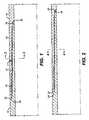
- FIG. 1is an elevation in section of the connection after makeup and before expansion
- FIG. 2is the view of FIG. 1 after expansion
- FIG. 3is a section along line 3 — 3 of FIG. 1;
- FIG. 4is a section along line 4 — 4 of FIG. 2;
- FIG. 5is the view along line 5 — 5 of FIG. 3;
- FIG. 6is an alternative design to the locking profile shown in FIG. 5;
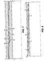
- FIG. 7is a more detailed view of FIG. 2;
- FIG. 8is an alternative embodiment showing a pair of resilient seals.
- the connectioncomprises a pin 10 threaded into a box 12 .
- a two-step threadis illustrated comprising thread pairs 14 and 16 , which are spaced apart to allow the placement of a resilient seal 17 and the locking feature L in between.
- the pin end 18is against a torque shoulder 20 on the box 12 .
- the box end 22is against a torque shoulder on the on the pin end 24 .
- a two-step threadis illustrated, a single or multi-step thread or other ways to connect the pin 10 to the box 12 are within the scope of the invention.
- the connectioncould be a bayonet type involving pushing the pin 10 into the box 12 and relatively rotating them into a made up position, prior to expansion downhole.
- the locking feature Lcan be used alone, without the resilient seal 17 .
- One or more resilient seals 17can be used, with or without the locking feature L.
- the pin and box endsare against their respective torque shoulders to hold the applied torque to the joint on makeup.
- the pin end 18has reduced in length and pulled away from its corresponding torque shoulder 20 .
- the box end 22has pulled away from its corresponding torque shoulder 24 .
- the locking feature Lengages as a result of the expansion.
- the downhole expansioncould be accomplished in a variety of ways, as contemplated in the present invention. A swage, applied pressure, or an inflatable are but three of the various ways contemplated to carry out the downhole expansinon.
- FIG. 4shows a pattern of parallel ridges as one of the surface treatments for these surfaces and FIG. 6 shows an alternative diamond pattern.
- the parallel ridgesare preferably oriented in alignment with the longitudinal axis of the joint.
- the inventioncontemplates a wide variation of surface treatments for surfaces 26 and 28 , with the desired objective being that the joint is locked together after expansion as these surfaces engage. These surfaces do not need to have identical patterns that engage.
- one surfacecan have a surface treatment and can engage the opposing cylindrical surface, which has no surface treatment.
- the surface treatmentcan be created in a variety of ways by either removing material from the surface or adding material to it.
- the surface treatmentcan be in an ordered pattern or a random array of projections and associated depressions.
- the overlap between the surface treatment on surfaces 26 and 28can be total or partial.
- the projectionscan have a variety of configurations and dimensions. The limiting factor is that projections from surfaces 26 and 28 should not contact each other when the joint is made up.
- the locking aspectarises from inter-engagement, which occurs after the expansion downhole.
- FIG. 4illustrates in more detail the engaged surfaces 26 and 28 of the locking feature L. It also illustrates the combination of the locking feature L with a single resilient seal 17 .
- Seal 17is disposed in a groove 30 in surface 32 . Seal 17 extends beyond surface 32 into contact with surface 34 as the joint is torqued up at the surface. After makeup, surfaces 32 and 34 are spaced apart, as would be necessary to allow the joint to be made up. However, after expansion surfaces 32 and 34 are in contact with preferably zero clearance. The contact may be tight enough to form a metal-to-metal seal between these surfaces, above or/and below seal 17 . In any event, the clearance is preferably eliminated taking away a common failure mode of resilient seals such as 17 .
- the seal 17may be in the middle of the thread, as shown if FIG. 7, or in any position with respect to the thread, as contemplated by the invention.
- the locking feature Lcan be in any position with respect to the thread and not only between steps of a two-step thread, as shown in FIG. 7 .
- the locking featurecan be above or below the thread and the thread can be in a variety of configurations including but not limited to multi-step threads.
- FIG. 8illustrates the use of at least two resilient or other type of seals 17 and 17 ′.
- seals 17 and 17 ′are above and below the thread pairs 14 and 16 creating a trapped annular volume 36 between the pin 10 and the box 12 when the joint is made up at the surface.
- the locking feature Lis shown disposed between the thread pairs 14 and 16 .
Landscapes
- Engineering & Computer Science (AREA)
- Chemical & Material Sciences (AREA)
- Mining & Mineral Resources (AREA)
- Geology (AREA)
- Life Sciences & Earth Sciences (AREA)
- Mechanical Engineering (AREA)
- General Life Sciences & Earth Sciences (AREA)
- Fluid Mechanics (AREA)
- Environmental & Geological Engineering (AREA)
- Physics & Mathematics (AREA)
- Geochemistry & Mineralogy (AREA)
- Chemical Kinetics & Catalysis (AREA)
- Materials Engineering (AREA)
- Metallurgy (AREA)
- Organic Chemistry (AREA)
- General Engineering & Computer Science (AREA)
- Laying Of Electric Cables Or Lines Outside (AREA)
- Earth Drilling (AREA)
Abstract
Description
The field of the invention is tubular connections, which are expanded downhole, and more particularly threads that retain makeup torque despite longitudinal shrinkage resulting from expansion downhole.
Oilfield tubular joints comprise a threaded pin and box which are made up against one or more torque shoulders with a force than can exceed 3000 foot pounds. Some designs further incorporate a resilient seal. One of the problems with such seals is that they fail because of a residual clearance in the seal area between the pin and the box, after makeup. When such joints are used downhole and expanded, longitudinal shrinkage at the pin end results in a pulling away of the pin end from the torque shoulder on the box. This allows very low torque levels to undo the connection with values as low as 200 foot-pounds or less. This longitudinal shrinkage can also eliminate the metal-to-metal seal, which existed after makeup and before expansion.
The present invention seeks to overcome, or at least alleviate, these shortcomings of the prior designs. It provides for a locking feature that retains the makeup torque and that is energized due to the expansion. It reduces or eliminates clearance around resilient seals due to the expansion. It also seeks to enhance the locking feature using spaced seals, which can trap atmospheric pressure between them, such that upon insertion downhole, hydrostatic pressure can push the box into the pin to better engage a locking feature. These and other advantages of the present invention can be more readily appreciated by a review of the detailed description of the preferred embodiment, which appears below.
A thread for expandable downhole tubular connections is disclosed. It features a locking pattern on the pin and box, which engages upon expansion of the connection. The locking pattern compensates for longitudinal shrinkage away from a torque shoulder, as a result of expansion. A resilient seal can be incorporated into the design with pin to box clearance disappearing around the seal as a result of expansion. Resilient seals can be used in tandem to trap atmospheric pressure between them. The wellbore hydrostatic pressure helps engage the locking feature by pushing the box into the pin, helped by the trapped low pressure between the seals.
FIG. 1 is an elevation in section of the connection after makeup and before expansion;
FIG. 2 is the view of FIG. 1 after expansion;
FIG. 3 is a section alongline 3—3 of FIG. 1;
FIG. 4 is a section alongline 4—4 of FIG. 2;
FIG. 5 is the view alongline 5—5 of FIG. 3;
FIG. 6 is an alternative design to the locking profile shown in FIG. 5;
FIG. 7 is a more detailed view of FIG. 2; and
FIG. 8 is an alternative embodiment showing a pair of resilient seals.
Referring to FIG. 1, the connection comprises apin 10 threaded into abox 12. A two-step thread is illustrated comprisingthread pairs resilient seal 17 and the locking feature L in between. Upon makeup, thepin end 18 is against atorque shoulder 20 on thebox 12. Thebox end 22 is against a torque shoulder on the on thepin end 24. While a two-step thread is illustrated, a single or multi-step thread or other ways to connect thepin 10 to thebox 12 are within the scope of the invention. For example, the connection could be a bayonet type involving pushing thepin 10 into thebox 12 and relatively rotating them into a made up position, prior to expansion downhole. A wide variety of thread forms can also be used in the connection of the present invention. The locking feature L can be used alone, without theresilient seal 17. One or moreresilient seals 17 can be used, with or without the locking feature L. These combinations and their benefits will be described in more detail below.
As seen in FIG. 1, when the joint is made up the pin and box ends are against their respective torque shoulders to hold the applied torque to the joint on makeup. However, upon expansion, as shown in FIG. 2, thepin end 18 has reduced in length and pulled away from itscorresponding torque shoulder 20. Similarly, thebox end 22 has pulled away from itscorresponding torque shoulder 24. To prevent very low applied torques from undoing the joint after downhole expansion, the locking feature L, engages as a result of the expansion. It should be noted that the downhole expansion could be accomplished in a variety of ways, as contemplated in the present invention. A swage, applied pressure, or an inflatable are but three of the various ways contemplated to carry out the downhole expansinon.
As a result of the expansion downhole,surfaces Surface 26 is disposed on thepin 10 andsurface 28 is on thebox 12. These surfaces face each other and can be continuous or discontinuous. FIG. 5 shows a pattern of parallel ridges as one of the surface treatments for these surfaces and FIG. 6 shows an alternative diamond pattern. The parallel ridges are preferably oriented in alignment with the longitudinal axis of the joint. The invention contemplates a wide variation of surface treatments forsurfaces surfaces surfaces
FIG. 4 illustrates in more detail theengaged surfaces resilient seal 17. Seal17 is disposed in agroove 30 insurface 32.Seal 17 extends beyondsurface 32 into contact withsurface 34 as the joint is torqued up at the surface. After makeup,surfaces expansion surfaces seal 17. In any event, the clearance is preferably eliminated taking away a common failure mode of resilient seals such as17. Theseal 17 may be in the middle of the thread, as shown if FIG. 7, or in any position with respect to the thread, as contemplated by the invention. Similarly, the locking feature L can be in any position with respect to the thread and not only between steps of a two-step thread, as shown in FIG.7. The locking feature can be above or below the thread and the thread can be in a variety of configurations including but not limited to multi-step threads.
FIG. 8 illustrates the use of at least two resilient or other type ofseals annular volume 36 between thepin 10 and thebox 12 when the joint is made up at the surface. The locking feature L is shown disposed between the thread pairs14 and16. When the joint goes downhole, hydrostatic pressures act on the outside of thebox 12 pushing it toward thepin 10 because the pressure in theannular volume 36 is still only atmospheric. The result is a reduction of volume ofannular volume 36 to the point where the residual pressure can be sufficient to engage thesurfaces
The above description is illustrative of the preferred embodiment and many modifications may be made by those skilled in the art without departing from the invention whose scope is to be determined from the literal and equivalent scope of the claims below.
Claims (20)
1. A connection between a pin and a box of adjacent tubulars, comprising:
a pin having an outer surface and configured for insertion into a box having an inner surface, said pin and box respectively comprising an engaging area to allow said pin and box to be torqued together; and
a locking surface treatment on one of said inner and outer surfaces that comes into contact with an opposing surface solely by radial expansion of said pin in said box after they are torqued together.
2. The connection ofclaim 1 , wherein:
said surface treatment is disposed on both said inner and outer surfaces so as to contact upon radial expansion of said pin and box.
3. The connection ofclaim 1 , wherein:
said surface treatment comprises parallel ridges.
4. The connection ofclaim 3 , wherein:
said pin and box have a longitudinal axis and said ridges are in substantial alignment with said longitudinal axis.
5. The connection ofclaim 1 , wherein:
said surface treatment comprises a plurality of projections.
6. The connection ofclaim 5 , wherein:
said projections are disposed on both said inner and outer surfaces so as to lockingly engage upon radial expansion of said pin and box.
7. A connection between a pin and a box of adjacent tubulars, comprising:
a pin having an outer surface and configured for insertion into a box having an inner surface, said pin and box respectively comprising an engaging area to allow said pin and box to be torqued together; and
a locking surface treatment on one of said inner and outer surfaces that comes into contact with an opposing surface solely by radial expansion of said pin and said box after they are torqued together; and
at least one seal protruding from at least one of said inner and outer surfaces and engaging the other of said inner and outer surfaces as said pin and box are made up, whereupon radial expansion of said pin and box.
8. A connection between a pin and a box of adjacent tubulars, comprising:
a pin having an outer surface and configured for insertion into a box having an inner surface, said pin and box respectively comprising an engaging area to allow said pin and box to be torqued together; and
a locking surface treatment on one of said inner and outer surfaces that comes into contact with an opposing surface solely by radial expansion of said pin and said box after they are torqued together; and
at least two seals protruding from at least one of said inner and outer surfaces and engaging the other of said inner and outer surfaces as said pin and box are made up to define an enclosed annular cavity trapping the ambient pressure upon makeup of said pin and said box, whereupon being subjected to external hydrostatic pressure downhole, said inner surface moves toward said outer surface to move said surface treatment toward a locking engagement of said pin and said box.
9. A connection between a pin and a box of adjacent tubulars, comprising:
a pin having an outer surface and configured for insertion into a box having an inner surface, said pin and box respectively comprising an engaging area to allow said pin and box to be torqued together; and
a locking surface treatment on one of said inner and outer surfaces that comes into contact with an opposing surface solely by radial expansion of said pin and said box after they are torqued together; and
said surface treatment comprises a diamond pattern.
10. A connection between a pin and a box of adjacent tubulars, comprising:
a pin having an outer surface and configured for insertion into a box having an inner surface, said pin and box respectively comprising an engaging area to allow said pin and box to be torqued together; and
a locking surface treatment on one of said inner and outer surfaces that comes into contact with an opposing surface solely by radial expansion of said pin and said box after they are torqued together;
said surface treatment comprises a plurality of projections;
said projections are disposed on both said inner and outer surfaces so as to lockingly engage upon radial expansion of said pin and box; and
at least one seal protruding from at least one of said inner and outer surfaces and engaging the other of said inner and outer surfaces as said pin and box are made up, whereupon radial expansion of said pin and box after makeup clearance between said outer and inner surfaces on at least one side of said seal is eliminated.
11. A connection between a pin and a box of adjacent tubulars, comprising:
a pin having an outer surface and configured for insertion into a box having an inner surface, said pin and box respectively comprising an engaging area to allow said pin and box to be torqued together; and
a locking surface treatment on one of said inner and outer surfaces that comes into contact with an opposing surface solely by radial expansion of said pin and said box after they are torqued together;
said surface treatment comprises a plurality of projections;
said projections are disposed on both said inner and outer surfaces so as to lockingly engage upon radial expansion of said pin and box; and
at least two seals protruding from at least one of said inner and outer surfaces and engaging the other of said inner and outer surfaces as said pin and box are made up to define an enclosed annular cavity trapping the ambient pressure upon makeup of said pin and said box, whereupon being subjected to external hydrostatic pressure downhole, said inner surface moves toward said outer surface to move said surface treatment toward a locking engagement of said pin and said box.
12. A connection between a pin and a box of adjacent tubulars, comprising:
a pin having an outer surface and configured for insertion into a box having an inner surface, said pin and box respectively comprising an engaging area to allow said pin and box to be torqued together;
at least two seals protruding from at least one of said inner and outer surfaces and engaging the other of said inner and outer surfaces as said pin and box are made up to define an enclosed annular cavity trapping the ambient pressure upon makeup of said pin and said box, whereupon being subjected to external hydrostatic pressure downhole after makeup, said inner surface moves against said outer surface create a locking engagement of said pin and said box.
13. The connection ofclaim 12 , wherein:
said pin outer surface and said box inner surface, upon being subject to radial expansion, move into contact with each other in a locking relationship due to at least one of said outer surface and inner surface having a surface treatment to promote said locking.
14. The connection ofclaim 13 , wherein:
said surface treatment comprises a plurality of projections.
15. The connection ofclaim 14 , wherein:
said projections are disposed on both said inner and outer surfaces so as to lockingly engage upon radial expansion of said pin and box.
16. A connection between a pin and a box of adjacent tubulars, comprising:
a pin having an outer surface and configured for insertion into a box having an inner surface, said pin and box respectively comprising an engaging area to allow said pin and box to be torqued together;
at least one seal protruding from at least one of said inner and outer surfaces and engaging the other of said inner and outer surfaces as said pin and box are made up, whereupon radial expansion of said pin and box after makeup, clearance between said outer and inner surfaces on at least one side of said seal is eliminated.
17. The connection ofclaim 16 , wherein:
said pin outer surface and said box inner surface, upon being subject to radial expansion, move into contact with each other in a locking relationship due to at least one of said outer surface and inner surface having a surface, treatment to promote said locking; and
said surface treatment comprises a plurality of projections.
18. The connection ofclaim 17 , wherein:
said projections are disposed on both said inner and outer surfaces so as to lockingly engage upon radial expansion of said pin and box.
19. The connection ofclaim 18 , wherein:
said surface treatment comprises parallel ridges.
20. The connection ofclaim 19 , wherein:
said pin and box have a longitudinal axis and said ridges are in substantial alignment with said longitudinal axis.
Priority Applications (9)
| Application Number | Priority Date | Filing Date | Title |
|---|---|---|---|
| US10/010,866US6619696B2 (en) | 2001-12-06 | 2001-12-06 | Expandable locking thread joint |
| US10/177,984US6792665B2 (en) | 2001-12-06 | 2002-06-21 | Method of securing a connection against breakout torque |
| PCT/US2002/038650WO2003050386A1 (en) | 2001-12-06 | 2002-12-04 | Expandable locking thread joint |
| GB0412420AGB2399581B (en) | 2001-12-06 | 2002-12-04 | Expandable locking thread joint |
| GB0510179AGB2411192B (en) | 2001-12-06 | 2002-12-04 | Expandable locking thread joint |
| AU2002362049AAU2002362049B2 (en) | 2001-12-06 | 2002-12-04 | Expandable locking thread joint |
| CA002469392ACA2469392C (en) | 2001-12-06 | 2002-12-04 | Expandable locking thread joint |
| GB0510181AGB2411680B (en) | 2001-12-06 | 2002-12-04 | Expandable locking thread joint |
| NO20042841ANO20042841L (en) | 2001-12-06 | 2004-07-05 | Expandable laser thread connection |
Applications Claiming Priority (1)
| Application Number | Priority Date | Filing Date | Title |
|---|---|---|---|
| US10/010,866US6619696B2 (en) | 2001-12-06 | 2001-12-06 | Expandable locking thread joint |
Related Child Applications (1)
| Application Number | Title | Priority Date | Filing Date |
|---|---|---|---|
| US10/177,984Continuation-In-PartUS6792665B2 (en) | 2001-12-06 | 2002-06-21 | Method of securing a connection against breakout torque |
Publications (2)
| Publication Number | Publication Date |
|---|---|
| US20030107213A1 US20030107213A1 (en) | 2003-06-12 |
| US6619696B2true US6619696B2 (en) | 2003-09-16 |
Family
ID=21747791
Family Applications (1)
| Application Number | Title | Priority Date | Filing Date |
|---|---|---|---|
| US10/010,866Expired - Fee RelatedUS6619696B2 (en) | 2001-12-06 | 2001-12-06 | Expandable locking thread joint |
Country Status (1)
| Country | Link |
|---|---|
| US (1) | US6619696B2 (en) |
Cited By (75)
| Publication number | Priority date | Publication date | Assignee | Title |
|---|---|---|---|---|
| US20030094277A1 (en)* | 1998-12-07 | 2003-05-22 | Shell Oil Co. | Expansion cone for radially expanding tubular members |
| US20030098162A1 (en)* | 1998-12-07 | 2003-05-29 | Shell Oil Company | Method of inserting a tubular member into a wellbore |
| US20030107217A1 (en)* | 1999-10-12 | 2003-06-12 | Shell Oil Co. | Sealant for expandable connection |
| US20030192705A1 (en)* | 1999-03-11 | 2003-10-16 | Shell Oil Co. | Forming a wellbore casing while simultaneously drilling a wellbore |
| US20030222409A1 (en)* | 1999-12-09 | 2003-12-04 | Sivley Robert S. | Non-rotating expandable connection with collapsing type seal |
| US20030234538A1 (en)* | 2002-06-24 | 2003-12-25 | Weatherford/Lamb, Inc. | Multi-point high pressure seal for expandable tubular connections |
| US20040090068A1 (en)* | 2002-11-07 | 2004-05-13 | Evans M. Edward | Method and apparatus for sealing radially expanded joints |
| US20040113428A1 (en)* | 2002-09-25 | 2004-06-17 | Macaulay Iain Cameron | Expandable connection |
| US20050012278A1 (en)* | 2002-11-07 | 2005-01-20 | Delange Richard W. | Metal sleeve seal for threaded connections |
| US6857473B2 (en) | 1999-02-26 | 2005-02-22 | Shell Oil Company | Method of coupling a tubular member to a preexisting structure |
| US20050133223A1 (en)* | 2003-12-19 | 2005-06-23 | Harrall Simon J. | Expandable tubular connection |
| US20050236834A1 (en)* | 2004-04-21 | 2005-10-27 | Baker Hughes Incorporated | Expandable tubular connection |
| US6968618B2 (en)* | 1999-04-26 | 2005-11-29 | Shell Oil Company | Expandable connector |
| US6976541B2 (en) | 2000-09-18 | 2005-12-20 | Shell Oil Company | Liner hanger with sliding sleeve valve |
| US7021390B2 (en) | 1998-12-07 | 2006-04-04 | Shell Oil Company | Tubular liner for wellbore casing |
| US7048067B1 (en) | 1999-11-01 | 2006-05-23 | Shell Oil Company | Wellbore casing repair |
| US20060131880A1 (en)* | 2002-06-10 | 2006-06-22 | Weatherford/Lamb Inc. | Pre-expanded connector for expandable downhole tubulars |
| US7077211B2 (en) | 1998-12-07 | 2006-07-18 | Shell Oil Company | Method of creating a casing in a borehole |
| US20060162145A1 (en)* | 2003-03-07 | 2006-07-27 | Vallourec Mannesmann Oil & Gas France | Method for producing a treaded tubular connection sealed by radial expansion |
| US7100684B2 (en) | 2000-07-28 | 2006-09-05 | Enventure Global Technology | Liner hanger with standoffs |
| US7100685B2 (en) | 2000-10-02 | 2006-09-05 | Enventure Global Technology | Mono-diameter wellbore casing |
| US7147053B2 (en) | 1998-12-07 | 2006-12-12 | Shell Oil Company | Wellhead |
| US7168499B2 (en) | 1998-11-16 | 2007-01-30 | Shell Oil Company | Radial expansion of tubular members |
| US7168496B2 (en) | 2001-07-06 | 2007-01-30 | Eventure Global Technology | Liner hanger |
| US20070024053A1 (en)* | 2005-07-28 | 2007-02-01 | Sivley Robert S Iv | Mid-seal for expandable connections |
| US7172024B2 (en) | 2000-10-02 | 2007-02-06 | Shell Oil Company | Mono-diameter wellbore casing |
| US20070035132A1 (en)* | 2005-08-11 | 2007-02-15 | Grinaldi Ltd | Expandable tubular connection |
| US20070035130A1 (en)* | 2005-08-11 | 2007-02-15 | Weatherford/Lamb, Inc. | Reverse sliding seal for expandable tubular connections |
| US7185710B2 (en) | 1998-12-07 | 2007-03-06 | Enventure Global Technology | Mono-diameter wellbore casing |
| US7195064B2 (en) | 1998-12-07 | 2007-03-27 | Enventure Global Technology | Mono-diameter wellbore casing |
| US7231985B2 (en) | 1998-11-16 | 2007-06-19 | Shell Oil Company | Radial expansion of tubular members |
| US7234531B2 (en) | 1999-12-03 | 2007-06-26 | Enventure Global Technology, Llc | Mono-diameter wellbore casing |
| US7240728B2 (en) | 1998-12-07 | 2007-07-10 | Shell Oil Company | Expandable tubulars with a radial passage and wall portions with different wall thicknesses |
| US7258168B2 (en) | 2001-07-27 | 2007-08-21 | Enventure Global Technology L.L.C. | Liner hanger with slip joint sealing members and method of use |
| US7290605B2 (en) | 2001-12-27 | 2007-11-06 | Enventure Global Technology | Seal receptacle using expandable liner hanger |
| US7290616B2 (en) | 2001-07-06 | 2007-11-06 | Enventure Global Technology, L.L.C. | Liner hanger |
| US20070257486A1 (en)* | 2006-05-03 | 2007-11-08 | Grinaldi Ltd. | Elastomeric Seal for Expandable Connector |
| US7308755B2 (en) | 2003-06-13 | 2007-12-18 | Shell Oil Company | Apparatus for forming a mono-diameter wellbore casing |
| US7325602B2 (en) | 2000-10-02 | 2008-02-05 | Shell Oil Company | Method and apparatus for forming a mono-diameter wellbore casing |
| US7350563B2 (en) | 1999-07-09 | 2008-04-01 | Enventure Global Technology, L.L.C. | System for lining a wellbore casing |
| US7360591B2 (en) | 2002-05-29 | 2008-04-22 | Enventure Global Technology, Llc | System for radially expanding a tubular member |
| US7363984B2 (en) | 1998-12-07 | 2008-04-29 | Enventure Global Technology, Llc | System for radially expanding a tubular member |
| US7377326B2 (en) | 2002-08-23 | 2008-05-27 | Enventure Global Technology, L.L.C. | Magnetic impulse applied sleeve method of forming a wellbore casing |
| US7383889B2 (en) | 2001-11-12 | 2008-06-10 | Enventure Global Technology, Llc | Mono diameter wellbore casing |
| US7398832B2 (en) | 2002-06-10 | 2008-07-15 | Enventure Global Technology, Llc | Mono-diameter wellbore casing |
| US7404444B2 (en) | 2002-09-20 | 2008-07-29 | Enventure Global Technology | Protective sleeve for expandable tubulars |
| US7410000B2 (en) | 2001-01-17 | 2008-08-12 | Enventure Global Technology, Llc. | Mono-diameter wellbore casing |
| US7416027B2 (en) | 2001-09-07 | 2008-08-26 | Enventure Global Technology, Llc | Adjustable expansion cone assembly |
| US7424918B2 (en) | 2002-08-23 | 2008-09-16 | Enventure Global Technology, L.L.C. | Interposed joint sealing layer method of forming a wellbore casing |
| US7438133B2 (en) | 2003-02-26 | 2008-10-21 | Enventure Global Technology, Llc | Apparatus and method for radially expanding and plastically deforming a tubular member |
| WO2007047193A3 (en)* | 2005-10-11 | 2008-10-23 | Enventure Global Technology | Method and apparatus for coupling expandable tubular members |
| US7503393B2 (en) | 2003-01-27 | 2009-03-17 | Enventure Global Technology, Inc. | Lubrication system for radially expanding tubular members |
| US7513313B2 (en) | 2002-09-20 | 2009-04-07 | Enventure Global Technology, Llc | Bottom plug for forming a mono diameter wellbore casing |
| US7516790B2 (en) | 1999-12-03 | 2009-04-14 | Enventure Global Technology, Llc | Mono-diameter wellbore casing |
| US7552776B2 (en) | 1998-12-07 | 2009-06-30 | Enventure Global Technology, Llc | Anchor hangers |
| US7571774B2 (en) | 2002-09-20 | 2009-08-11 | Eventure Global Technology | Self-lubricating expansion mandrel for expandable tubular |
| US20090205839A1 (en)* | 2003-01-09 | 2009-08-20 | Shell Oil Company | Expandable connection |
| US7603758B2 (en) | 1998-12-07 | 2009-10-20 | Shell Oil Company | Method of coupling a tubular member |
| US20100052319A1 (en)* | 2008-08-28 | 2010-03-04 | Mohawk Energy Ltd. | Dual Seal Expandable Tubular Connection |
| US7712522B2 (en) | 2003-09-05 | 2010-05-11 | Enventure Global Technology, Llc | Expansion cone and system |
| US20100132956A1 (en)* | 2008-12-01 | 2010-06-03 | Enventure Global Technology, L.L.C. | Expandable connection with metal to metal seal |
| US7739917B2 (en) | 2002-09-20 | 2010-06-22 | Enventure Global Technology, Llc | Pipe formability evaluation for expandable tubulars |
| US7740076B2 (en) | 2002-04-12 | 2010-06-22 | Enventure Global Technology, L.L.C. | Protective sleeve for threaded connections for expandable liner hanger |
| US7775290B2 (en) | 2003-04-17 | 2010-08-17 | Enventure Global Technology, Llc | Apparatus for radially expanding and plastically deforming a tubular member |
| US20100225107A1 (en)* | 2006-02-17 | 2010-09-09 | Norsk Hydro Asa | Gas Tight Tubular Joint or Connection |
| US7793721B2 (en) | 2003-03-11 | 2010-09-14 | Eventure Global Technology, Llc | Apparatus for radially expanding and plastically deforming a tubular member |
| US20100230958A1 (en)* | 2005-09-28 | 2010-09-16 | Enventure Global Technology, L.L.C. | Method and Apparatus for coupling Expandable Tubular Members |
| US7819185B2 (en) | 2004-08-13 | 2010-10-26 | Enventure Global Technology, Llc | Expandable tubular |
| US20110000664A1 (en)* | 2009-07-01 | 2011-01-06 | Adam Mark K | Non-collapsing Built in Place Adjustable Swage |
| US7886831B2 (en) | 2003-01-22 | 2011-02-15 | Enventure Global Technology, L.L.C. | Apparatus for radially expanding and plastically deforming a tubular member |
| US7887103B2 (en) | 2003-05-22 | 2011-02-15 | Watherford/Lamb, Inc. | Energizing seal for expandable connections |
| US7895726B2 (en) | 2003-05-22 | 2011-03-01 | Weatherford/Lamb, Inc. | Tubing connector and method of sealing tubing sections |
| US7918284B2 (en) | 2002-04-15 | 2011-04-05 | Enventure Global Technology, L.L.C. | Protective sleeve for threaded connections for expandable liner hanger |
| US9677346B2 (en) | 2012-11-28 | 2017-06-13 | Ultra Premium Oilfield Services, Ltd. | Tubular connection with helically extending torque shoulder |
| US9869139B2 (en) | 2012-11-28 | 2018-01-16 | Ultra Premium Oilfield Services, Ltd. | Tubular connection with helically extending torque shoulder |
Families Citing this family (9)
| Publication number | Priority date | Publication date | Assignee | Title |
|---|---|---|---|---|
| US20070034274A1 (en)* | 2000-07-27 | 2007-02-15 | Proteus, Inc. | Extrusion apparatus |
| FR2844331B1 (en)* | 2002-01-03 | 2004-11-26 | Vallourec Mannesmann Oil & Gas | PROCESS FOR PRODUCING A SEALED TUBULAR JOINT WITH PLASTIC EXPANSION |
| FR2841626B1 (en)* | 2002-06-28 | 2004-09-24 | Vallourec Mannesmann Oil & Gas | REINFORCED TUBULAR THREADED JOINT FOR IMPROVED SEALING AFTER PLASTIC EXPANSION |
| US6997264B2 (en)* | 2002-10-10 | 2006-02-14 | Weatherford/Lamb, Inc. | Method of jointing and running expandable tubulars |
| GB0317395D0 (en)* | 2003-07-25 | 2003-08-27 | Weatherford Lamb | Sealing expandable tubing |
| US20050052024A1 (en)* | 2003-09-09 | 2005-03-10 | Fox John Herrington | Coupling means for multi-wall pipes or tubes |
| FR2880097B1 (en)* | 2004-12-23 | 2007-03-30 | Philippe Nobileau | SEALED PIPE CONNECTOR |
| CN102996079A (en)* | 2011-09-16 | 2013-03-27 | 中国石油化工股份有限公司 | Tubular air sealing screwed joint and application thereof |
| JP6763542B2 (en)* | 2016-11-22 | 2020-09-30 | 住友電気工業株式会社 | Iron nitride material and method for manufacturing iron nitride material |
Citations (5)
| Publication number | Priority date | Publication date | Assignee | Title |
|---|---|---|---|---|
| US331940A (en)* | 1885-12-08 | Half to ralph bagaley | ||
| US332184A (en)* | 1885-12-08 | William a | ||
| US2160263A (en)* | 1937-03-18 | 1939-05-30 | Hughes Tool Co | Pipe joint and method of making same |
| US5044676A (en)* | 1990-01-05 | 1991-09-03 | Abbvetco Gray Inc. | Tubular threaded connector joint with separate interfering locking profile |
| US5785357A (en)* | 1995-09-22 | 1998-07-28 | Utd, Inc. | Locking joint |
- 2001
- 2001-12-06USUS10/010,866patent/US6619696B2/ennot_activeExpired - Fee Related
Patent Citations (5)
| Publication number | Priority date | Publication date | Assignee | Title |
|---|---|---|---|---|
| US331940A (en)* | 1885-12-08 | Half to ralph bagaley | ||
| US332184A (en)* | 1885-12-08 | William a | ||
| US2160263A (en)* | 1937-03-18 | 1939-05-30 | Hughes Tool Co | Pipe joint and method of making same |
| US5044676A (en)* | 1990-01-05 | 1991-09-03 | Abbvetco Gray Inc. | Tubular threaded connector joint with separate interfering locking profile |
| US5785357A (en)* | 1995-09-22 | 1998-07-28 | Utd, Inc. | Locking joint |
Cited By (129)
| Publication number | Priority date | Publication date | Assignee | Title |
|---|---|---|---|---|
| US7357190B2 (en) | 1998-11-16 | 2008-04-15 | Shell Oil Company | Radial expansion of tubular members |
| US7231985B2 (en) | 1998-11-16 | 2007-06-19 | Shell Oil Company | Radial expansion of tubular members |
| US7168499B2 (en) | 1998-11-16 | 2007-01-30 | Shell Oil Company | Radial expansion of tubular members |
| US7246667B2 (en) | 1998-11-16 | 2007-07-24 | Shell Oil Company | Radial expansion of tubular members |
| US7108072B2 (en) | 1998-11-16 | 2006-09-19 | Shell Oil Company | Lubrication and self-cleaning system for expansion mandrel |
| US7270188B2 (en) | 1998-11-16 | 2007-09-18 | Shell Oil Company | Radial expansion of tubular members |
| US7275601B2 (en) | 1998-11-16 | 2007-10-02 | Shell Oil Company | Radial expansion of tubular members |
| US7299881B2 (en) | 1998-11-16 | 2007-11-27 | Shell Oil Company | Radial expansion of tubular members |
| US7121337B2 (en) | 1998-12-07 | 2006-10-17 | Shell Oil Company | Apparatus for expanding a tubular member |
| US7048062B2 (en) | 1998-12-07 | 2006-05-23 | Shell Oil Company | Method of selecting tubular members |
| US7185710B2 (en) | 1998-12-07 | 2007-03-06 | Enventure Global Technology | Mono-diameter wellbore casing |
| US7195064B2 (en) | 1998-12-07 | 2007-03-27 | Enventure Global Technology | Mono-diameter wellbore casing |
| US7198100B2 (en) | 1998-12-07 | 2007-04-03 | Shell Oil Company | Apparatus for expanding a tubular member |
| US7434618B2 (en) | 1998-12-07 | 2008-10-14 | Shell Oil Company | Apparatus for expanding a tubular member |
| US7419009B2 (en) | 1998-12-07 | 2008-09-02 | Shell Oil Company | Apparatus for radially expanding and plastically deforming a tubular member |
| US7011161B2 (en) | 1998-12-07 | 2006-03-14 | Shell Oil Company | Structural support |
| US7363984B2 (en) | 1998-12-07 | 2008-04-29 | Enventure Global Technology, Llc | System for radially expanding a tubular member |
| US7021390B2 (en) | 1998-12-07 | 2006-04-04 | Shell Oil Company | Tubular liner for wellbore casing |
| US7036582B2 (en) | 1998-12-07 | 2006-05-02 | Shell Oil Company | Expansion cone for radially expanding tubular members |
| US7174964B2 (en) | 1998-12-07 | 2007-02-13 | Shell Oil Company | Wellhead with radially expanded tubulars |
| US7044218B2 (en) | 1998-12-07 | 2006-05-16 | Shell Oil Company | Apparatus for radially expanding tubular members |
| US7195061B2 (en) | 1998-12-07 | 2007-03-27 | Shell Oil Company | Apparatus for expanding a tubular member |
| US7216701B2 (en) | 1998-12-07 | 2007-05-15 | Shell Oil Company | Apparatus for expanding a tubular member |
| US20030098162A1 (en)* | 1998-12-07 | 2003-05-29 | Shell Oil Company | Method of inserting a tubular member into a wellbore |
| US7552776B2 (en) | 1998-12-07 | 2009-06-30 | Enventure Global Technology, Llc | Anchor hangers |
| US7357188B1 (en) | 1998-12-07 | 2008-04-15 | Shell Oil Company | Mono-diameter wellbore casing |
| US7240728B2 (en) | 1998-12-07 | 2007-07-10 | Shell Oil Company | Expandable tubulars with a radial passage and wall portions with different wall thicknesses |
| US7077211B2 (en) | 1998-12-07 | 2006-07-18 | Shell Oil Company | Method of creating a casing in a borehole |
| US7350564B2 (en) | 1998-12-07 | 2008-04-01 | Enventure Global Technology, L.L.C. | Mono-diameter wellbore casing |
| US7077213B2 (en) | 1998-12-07 | 2006-07-18 | Shell Oil Company | Expansion cone for radially expanding tubular members |
| US7240729B2 (en) | 1998-12-07 | 2007-07-10 | Shell Oil Company | Apparatus for expanding a tubular member |
| US7086475B2 (en) | 1998-12-07 | 2006-08-08 | Shell Oil Company | Method of inserting a tubular member into a wellbore |
| US7603758B2 (en) | 1998-12-07 | 2009-10-20 | Shell Oil Company | Method of coupling a tubular member |
| US20030094277A1 (en)* | 1998-12-07 | 2003-05-22 | Shell Oil Co. | Expansion cone for radially expanding tubular members |
| US7665532B2 (en) | 1998-12-07 | 2010-02-23 | Shell Oil Company | Pipeline |
| US7147053B2 (en) | 1998-12-07 | 2006-12-12 | Shell Oil Company | Wellhead |
| US7159667B2 (en) | 1999-02-25 | 2007-01-09 | Shell Oil Company | Method of coupling a tubular member to a preexisting structure |
| US7044221B2 (en) | 1999-02-26 | 2006-05-16 | Shell Oil Company | Apparatus for coupling a tubular member to a preexisting structure |
| US6857473B2 (en) | 1999-02-26 | 2005-02-22 | Shell Oil Company | Method of coupling a tubular member to a preexisting structure |
| US7556092B2 (en) | 1999-02-26 | 2009-07-07 | Enventure Global Technology, Llc | Flow control system for an apparatus for radially expanding tubular members |
| US20030192705A1 (en)* | 1999-03-11 | 2003-10-16 | Shell Oil Co. | Forming a wellbore casing while simultaneously drilling a wellbore |
| US7438132B2 (en) | 1999-03-11 | 2008-10-21 | Shell Oil Company | Concentric pipes expanded at the pipe ends and method of forming |
| US7055608B2 (en) | 1999-03-11 | 2006-06-06 | Shell Oil Company | Forming a wellbore casing while simultaneously drilling a wellbore |
| US6968618B2 (en)* | 1999-04-26 | 2005-11-29 | Shell Oil Company | Expandable connector |
| US7350563B2 (en) | 1999-07-09 | 2008-04-01 | Enventure Global Technology, L.L.C. | System for lining a wellbore casing |
| US20030107217A1 (en)* | 1999-10-12 | 2003-06-12 | Shell Oil Co. | Sealant for expandable connection |
| US7048067B1 (en) | 1999-11-01 | 2006-05-23 | Shell Oil Company | Wellbore casing repair |
| US7234531B2 (en) | 1999-12-03 | 2007-06-26 | Enventure Global Technology, Llc | Mono-diameter wellbore casing |
| US7516790B2 (en) | 1999-12-03 | 2009-04-14 | Enventure Global Technology, Llc | Mono-diameter wellbore casing |
| US20030222409A1 (en)* | 1999-12-09 | 2003-12-04 | Sivley Robert S. | Non-rotating expandable connection with collapsing type seal |
| US7100684B2 (en) | 2000-07-28 | 2006-09-05 | Enventure Global Technology | Liner hanger with standoffs |
| US7172021B2 (en) | 2000-09-18 | 2007-02-06 | Shell Oil Company | Liner hanger with sliding sleeve valve |
| US6976541B2 (en) | 2000-09-18 | 2005-12-20 | Shell Oil Company | Liner hanger with sliding sleeve valve |
| US7172024B2 (en) | 2000-10-02 | 2007-02-06 | Shell Oil Company | Mono-diameter wellbore casing |
| US7204007B2 (en) | 2000-10-02 | 2007-04-17 | Shell Oil Company | Method and apparatus for forming a mono-diameter wellbore casing |
| US7172019B2 (en) | 2000-10-02 | 2007-02-06 | Shell Oil Company | Method and apparatus for forming a mono-diameter wellbore casing |
| US7201223B2 (en) | 2000-10-02 | 2007-04-10 | Shell Oil Company | Method and apparatus for forming a mono-diameter wellbore casing |
| US7146702B2 (en) | 2000-10-02 | 2006-12-12 | Shell Oil Company | Method and apparatus for forming a mono-diameter wellbore casing |
| US7363691B2 (en) | 2000-10-02 | 2008-04-29 | Shell Oil Company | Method and apparatus for forming a mono-diameter wellbore casing |
| US7100685B2 (en) | 2000-10-02 | 2006-09-05 | Enventure Global Technology | Mono-diameter wellbore casing |
| US7363690B2 (en) | 2000-10-02 | 2008-04-29 | Shell Oil Company | Method and apparatus for forming a mono-diameter wellbore casing |
| US7325602B2 (en) | 2000-10-02 | 2008-02-05 | Shell Oil Company | Method and apparatus for forming a mono-diameter wellbore casing |
| US7410000B2 (en) | 2001-01-17 | 2008-08-12 | Enventure Global Technology, Llc. | Mono-diameter wellbore casing |
| US7290616B2 (en) | 2001-07-06 | 2007-11-06 | Enventure Global Technology, L.L.C. | Liner hanger |
| US7168496B2 (en) | 2001-07-06 | 2007-01-30 | Eventure Global Technology | Liner hanger |
| US7258168B2 (en) | 2001-07-27 | 2007-08-21 | Enventure Global Technology L.L.C. | Liner hanger with slip joint sealing members and method of use |
| US7416027B2 (en) | 2001-09-07 | 2008-08-26 | Enventure Global Technology, Llc | Adjustable expansion cone assembly |
| US7559365B2 (en) | 2001-11-12 | 2009-07-14 | Enventure Global Technology, Llc | Collapsible expansion cone |
| US7383889B2 (en) | 2001-11-12 | 2008-06-10 | Enventure Global Technology, Llc | Mono diameter wellbore casing |
| US7290605B2 (en) | 2001-12-27 | 2007-11-06 | Enventure Global Technology | Seal receptacle using expandable liner hanger |
| US7740076B2 (en) | 2002-04-12 | 2010-06-22 | Enventure Global Technology, L.L.C. | Protective sleeve for threaded connections for expandable liner hanger |
| US7918284B2 (en) | 2002-04-15 | 2011-04-05 | Enventure Global Technology, L.L.C. | Protective sleeve for threaded connections for expandable liner hanger |
| US7360591B2 (en) | 2002-05-29 | 2008-04-22 | Enventure Global Technology, Llc | System for radially expanding a tubular member |
| US7610667B2 (en)* | 2002-06-10 | 2009-11-03 | Weatherford/Lamb, Inc. | Method of connecting expandable tubulars |
| US20060131880A1 (en)* | 2002-06-10 | 2006-06-22 | Weatherford/Lamb Inc. | Pre-expanded connector for expandable downhole tubulars |
| US20060131881A1 (en)* | 2002-06-10 | 2006-06-22 | Weatherford/Lamb Inc. | Pre-expanded connector for expandable downhole tubulars |
| US20060131879A1 (en)* | 2002-06-10 | 2006-06-22 | Weatherford/Lamb Inc. | Pre-expanded connector for expandable downhole tubulars |
| US7478844B2 (en)* | 2002-06-10 | 2009-01-20 | Weatherford/Lamb, Inc. | Pre-expanded connector for expandable downhole tubulars |
| US7398832B2 (en) | 2002-06-10 | 2008-07-15 | Enventure Global Technology, Llc | Mono-diameter wellbore casing |
| US7621570B2 (en)* | 2002-06-10 | 2009-11-24 | Weatherford/Lamb, Inc. | Pre-expanded connector for expandable downhole tubulars |
| US6971685B2 (en)* | 2002-06-24 | 2005-12-06 | Weatherford/Lamb, Inc. | Multi-point high pressure seal for expandable tubular connections |
| US20030234538A1 (en)* | 2002-06-24 | 2003-12-25 | Weatherford/Lamb, Inc. | Multi-point high pressure seal for expandable tubular connections |
| US7377326B2 (en) | 2002-08-23 | 2008-05-27 | Enventure Global Technology, L.L.C. | Magnetic impulse applied sleeve method of forming a wellbore casing |
| US7424918B2 (en) | 2002-08-23 | 2008-09-16 | Enventure Global Technology, L.L.C. | Interposed joint sealing layer method of forming a wellbore casing |
| US7571774B2 (en) | 2002-09-20 | 2009-08-11 | Eventure Global Technology | Self-lubricating expansion mandrel for expandable tubular |
| US7513313B2 (en) | 2002-09-20 | 2009-04-07 | Enventure Global Technology, Llc | Bottom plug for forming a mono diameter wellbore casing |
| US7739917B2 (en) | 2002-09-20 | 2010-06-22 | Enventure Global Technology, Llc | Pipe formability evaluation for expandable tubulars |
| US7404444B2 (en) | 2002-09-20 | 2008-07-29 | Enventure Global Technology | Protective sleeve for expandable tubulars |
| US20040113428A1 (en)* | 2002-09-25 | 2004-06-17 | Macaulay Iain Cameron | Expandable connection |
| US7017950B2 (en) | 2002-09-25 | 2006-03-28 | Weatherford/Lamb, Inc. | Expandable connection |
| US7086669B2 (en)* | 2002-11-07 | 2006-08-08 | Grant Prideco, L.P. | Method and apparatus for sealing radially expanded joints |
| US20050012278A1 (en)* | 2002-11-07 | 2005-01-20 | Delange Richard W. | Metal sleeve seal for threaded connections |
| US20040090068A1 (en)* | 2002-11-07 | 2004-05-13 | Evans M. Edward | Method and apparatus for sealing radially expanded joints |
| US8205680B2 (en) | 2003-01-09 | 2012-06-26 | Enventure Global Technology, Llc | Expandable connection |
| US20090205839A1 (en)* | 2003-01-09 | 2009-08-20 | Shell Oil Company | Expandable connection |
| US7886831B2 (en) | 2003-01-22 | 2011-02-15 | Enventure Global Technology, L.L.C. | Apparatus for radially expanding and plastically deforming a tubular member |
| US7503393B2 (en) | 2003-01-27 | 2009-03-17 | Enventure Global Technology, Inc. | Lubrication system for radially expanding tubular members |
| US7438133B2 (en) | 2003-02-26 | 2008-10-21 | Enventure Global Technology, Llc | Apparatus and method for radially expanding and plastically deforming a tubular member |
| US20060162145A1 (en)* | 2003-03-07 | 2006-07-27 | Vallourec Mannesmann Oil & Gas France | Method for producing a treaded tubular connection sealed by radial expansion |
| US8151461B2 (en)* | 2003-03-07 | 2012-04-10 | Vallourec Mannesmann Oil & Gas France | Method for producing a threaded tubular connection sealed by radial expansion |
| US7793721B2 (en) | 2003-03-11 | 2010-09-14 | Eventure Global Technology, Llc | Apparatus for radially expanding and plastically deforming a tubular member |
| US7775290B2 (en) | 2003-04-17 | 2010-08-17 | Enventure Global Technology, Llc | Apparatus for radially expanding and plastically deforming a tubular member |
| US7887103B2 (en) | 2003-05-22 | 2011-02-15 | Watherford/Lamb, Inc. | Energizing seal for expandable connections |
| US7895726B2 (en) | 2003-05-22 | 2011-03-01 | Weatherford/Lamb, Inc. | Tubing connector and method of sealing tubing sections |
| US7308755B2 (en) | 2003-06-13 | 2007-12-18 | Shell Oil Company | Apparatus for forming a mono-diameter wellbore casing |
| US7712522B2 (en) | 2003-09-05 | 2010-05-11 | Enventure Global Technology, Llc | Expansion cone and system |
| US7077197B2 (en)* | 2003-12-19 | 2006-07-18 | Weatherford/Lamb, Inc. | Expandable tubular connection |
| US20050133223A1 (en)* | 2003-12-19 | 2005-06-23 | Harrall Simon J. | Expandable tubular connection |
| US20050236834A1 (en)* | 2004-04-21 | 2005-10-27 | Baker Hughes Incorporated | Expandable tubular connection |
| GB2430457B (en)* | 2004-04-21 | 2008-11-05 | Baker Hughes Inc | Expandable tubular connection |
| US7585002B2 (en)* | 2004-04-21 | 2009-09-08 | Baker Hughes Incorporated | Expandable tubular connection |
| US7819185B2 (en) | 2004-08-13 | 2010-10-26 | Enventure Global Technology, Llc | Expandable tubular |
| US8177262B2 (en)* | 2005-07-28 | 2012-05-15 | Hydril Company Lp | Mid-seal for expandable connections |
| US20070024053A1 (en)* | 2005-07-28 | 2007-02-01 | Sivley Robert S Iv | Mid-seal for expandable connections |
| US20100320754A1 (en)* | 2005-08-11 | 2010-12-23 | Hashem Ghazi J | Reverse sliding seal for expandable tubular connections |
| US7798536B2 (en) | 2005-08-11 | 2010-09-21 | Weatherford/Lamb, Inc. | Reverse sliding seal for expandable tubular connections |
| US20070035130A1 (en)* | 2005-08-11 | 2007-02-15 | Weatherford/Lamb, Inc. | Reverse sliding seal for expandable tubular connections |
| US20070035132A1 (en)* | 2005-08-11 | 2007-02-15 | Grinaldi Ltd | Expandable tubular connection |
| US20100230958A1 (en)* | 2005-09-28 | 2010-09-16 | Enventure Global Technology, L.L.C. | Method and Apparatus for coupling Expandable Tubular Members |
| US20090302604A1 (en)* | 2005-10-11 | 2009-12-10 | Enventure Global Technology, L.L.C. | Method and Apparatus for coupling Expandable Tubular Members |
| WO2007047193A3 (en)* | 2005-10-11 | 2008-10-23 | Enventure Global Technology | Method and apparatus for coupling expandable tubular members |
| US20100225107A1 (en)* | 2006-02-17 | 2010-09-09 | Norsk Hydro Asa | Gas Tight Tubular Joint or Connection |
| US20070257486A1 (en)* | 2006-05-03 | 2007-11-08 | Grinaldi Ltd. | Elastomeric Seal for Expandable Connector |
| US20100052319A1 (en)* | 2008-08-28 | 2010-03-04 | Mohawk Energy Ltd. | Dual Seal Expandable Tubular Connection |
| US20100132956A1 (en)* | 2008-12-01 | 2010-06-03 | Enventure Global Technology, L.L.C. | Expandable connection with metal to metal seal |
| US20110000664A1 (en)* | 2009-07-01 | 2011-01-06 | Adam Mark K | Non-collapsing Built in Place Adjustable Swage |
| US8627885B2 (en) | 2009-07-01 | 2014-01-14 | Baker Hughes Incorporated | Non-collapsing built in place adjustable swage |
| US9677346B2 (en) | 2012-11-28 | 2017-06-13 | Ultra Premium Oilfield Services, Ltd. | Tubular connection with helically extending torque shoulder |
| US9869139B2 (en) | 2012-11-28 | 2018-01-16 | Ultra Premium Oilfield Services, Ltd. | Tubular connection with helically extending torque shoulder |
Also Published As
| Publication number | Publication date |
|---|---|
| US20030107213A1 (en) | 2003-06-12 |
Similar Documents
| Publication | Publication Date | Title |
|---|---|---|
| US6619696B2 (en) | Expandable locking thread joint | |
| EP1106778B1 (en) | Seal for expandable tubular connections | |
| EP0957233B1 (en) | Threaded connector | |
| JP4688384B2 (en) | Expandable fitting coupler | |
| EP0897504B1 (en) | Threaded tool joint with dual mating shoulders | |
| EP1379804B1 (en) | Threaded connection | |
| US6997264B2 (en) | Method of jointing and running expandable tubulars | |
| US6976711B2 (en) | Threaded connection especially for radially plastically expandable conduit | |
| US7107663B2 (en) | Expandable coupling | |
| CA2577645C (en) | Energizing seal for expandable connections | |
| NZ210700A (en) | Screw pipe joint with helically tapered,chevron profiled thread form | |
| CA2288740A1 (en) | Threaded connection for enhanced fatigue resistance | |
| US20080007060A1 (en) | Coupling tubulars | |
| US20120049513A1 (en) | Non Threaded Drill Pipe Connection | |
| WO2010122431A1 (en) | Threaded joint for tubes, pipes and the like | |
| US3472538A (en) | Joint for coupling two tubular members together | |
| AU2002362049B2 (en) | Expandable locking thread joint | |
| US9599259B2 (en) | Oilfield threaded connections |
Legal Events
| Date | Code | Title | Description |
|---|---|---|---|
| AS | Assignment | Owner name:BAKER HUGHES INCORPORATED, TEXAS Free format text:ASSIGNMENT OF ASSIGNORS INTEREST;ASSIGNORS:BAUGH, JOHN L.;CARMODY, MICHAEL;REEL/FRAME:012372/0270 Effective date:20011205 | |
| FPAY | Fee payment | Year of fee payment:4 | |
| FPAY | Fee payment | Year of fee payment:8 | |
| REMI | Maintenance fee reminder mailed | ||
| LAPS | Lapse for failure to pay maintenance fees | ||
| STCH | Information on status: patent discontinuation | Free format text:PATENT EXPIRED DUE TO NONPAYMENT OF MAINTENANCE FEES UNDER 37 CFR 1.362 | |
| FP | Expired due to failure to pay maintenance fee | Effective date:20150916 |