US6619078B1 - Barrel lock - Google Patents
Barrel lockDownload PDFInfo
- Publication number
- US6619078B1 US6619078B1US09/735,289US73528900AUS6619078B1US 6619078 B1US6619078 B1US 6619078B1US 73528900 AUS73528900 AUS 73528900AUS 6619078 B1US6619078 B1US 6619078B1
- Authority
- US
- United States
- Prior art keywords
- body portion
- lock
- keyway
- section
- locking
- Prior art date
- Legal status (The legal status is an assumption and is not a legal conclusion. Google has not performed a legal analysis and makes no representation as to the accuracy of the status listed.)
- Expired - Lifetime
Links
- 239000007787solidSubstances0.000claimsabstractdescription5
- 230000000295complement effectEffects0.000claims1
- 210000002105tongueAnatomy0.000claims1
Images


Classifications
- E—FIXED CONSTRUCTIONS
- E05—LOCKS; KEYS; WINDOW OR DOOR FITTINGS; SAFES
- E05B—LOCKS; ACCESSORIES THEREFOR; HANDCUFFS
- E05B67/00—Padlocks; Details thereof
- E05B67/36—Padlocks with closing means other than shackles ; Removable locks, the lock body itself being the locking element; Padlocks consisting of two separable halves or cooperating with a stud
- E05B67/365—Padlocks with closing means other than shackles ; Removable locks, the lock body itself being the locking element; Padlocks consisting of two separable halves or cooperating with a stud with locking means in the form of balls or rollers
- Y—GENERAL TAGGING OF NEW TECHNOLOGICAL DEVELOPMENTS; GENERAL TAGGING OF CROSS-SECTIONAL TECHNOLOGIES SPANNING OVER SEVERAL SECTIONS OF THE IPC; TECHNICAL SUBJECTS COVERED BY FORMER USPC CROSS-REFERENCE ART COLLECTIONS [XRACs] AND DIGESTS
- Y10—TECHNICAL SUBJECTS COVERED BY FORMER USPC
- Y10T—TECHNICAL SUBJECTS COVERED BY FORMER US CLASSIFICATION
- Y10T70/00—Locks
- Y10T70/40—Portable
- Y10T70/413—Padlocks
- Y10T70/437—Key-controlled
- Y10T70/439—Non-shackle type
- Y10T70/443—Single stem or shank
- Y—GENERAL TAGGING OF NEW TECHNOLOGICAL DEVELOPMENTS; GENERAL TAGGING OF CROSS-SECTIONAL TECHNOLOGIES SPANNING OVER SEVERAL SECTIONS OF THE IPC; TECHNICAL SUBJECTS COVERED BY FORMER USPC CROSS-REFERENCE ART COLLECTIONS [XRACs] AND DIGESTS
- Y10—TECHNICAL SUBJECTS COVERED BY FORMER USPC
- Y10T—TECHNICAL SUBJECTS COVERED BY FORMER US CLASSIFICATION
- Y10T70/00—Locks
- Y10T70/70—Operating mechanism
- Y10T70/7441—Key
- Y10T70/7751—With ball or roller
Definitions
- the present inventionrelates to barrel locks and more specifically to an improved barrel lock assembly which is superior in its resistance to theft.
- An object of the present inventionis to provide a barrel lock structure which has a pair of generally cylindrically shaped lock body portions, one elongated and generally solid, the other short and generally hollow, and a means for axially locking the two portions together.
- the means for locking the two portions togetherincludes a spring biased lock structure assembled in one portion of the lock that is movable axially relative to the other portion.
- the spring biased lock structureincludes an axial extension that penetrates the first portion and for spreading a plurality of locking balls apart from each other and thereby lock the two portions together.
- the spring biased lock structurefurther includes a detent for engaging a shoulder provided in the first portion.
- the second lock portionis of generally the same external cylindrical dimension as the first section of the first portion and there is coaxially disposed within the hollow interior an axially moveable piston, the piston having a stepped shape that includes an axial extension terminating in a conical plunger pointed outwardly away from the main body portion of the axially movable plunger.
- a keywayadapted to receive a key of a selected variety.
- the spring biasing meansis supple enough to be overcome by axial force manually imposed in the opposite axial direction to compress the spring and thereby force the axially moveable piston in the opposite axial direction, and to to hold the piston in a desired position to engage the detent when said keyway mechanism is rotated cylindrically.
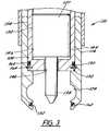
- FIG. 1is a vertical cross-sectional view of the barrel lock of the present invention illustrating the lock in the unsecured condition.
- FIG. 2is a similar vertical cross-sectional view of the barrel lock of the present invention illustrating the lock in the secured condition.
- FIG. 3is a vertical cross-sectional view of a second embodiment of the barrel lock of the present invention, which further includes sleeve and snap ring for the locking mechanism
- Structure 10includes two axially aligned body portions, first body portion 12 and second body portion 14 .
- First body portion 12is generally elongated and solid, having a first section at one end identified by the numeral 16 and being of the greatest diameter in cross-section through body portion 12 , and a second section 18 generally elongated relative to section 16 and being separated therefrom by a beveled shoulder 20 gradually stepping down the diameter between the two sections 16 and 18 while retaining the greatest strength possible.
- Sections 16 and 18are in axial alignment with each other.
- Second section 18 at the end remote from beveled shoulder 20is provided with a central coaxial cylindrical aperture 22 open at the end of section 18 remote from section 16 and shoulder 20 .
- Aperture 22includes a radial passageway that extend across the width of section 18 , and disposed internally of the radial passageway are a number of locking balls 26 , the balls being spheres that are smooth surfaced and of a diameter such that when they are in place in the cylindrical aperture 22 they touch each other and are unable to escape the aperture 22 .
- second body portion 14is seen also as being in axial alignment with first body portion 12 .
- Second body portion 14is generally hollow and includes internal passageway 28 .
- the second body portion 14includes an open end for receiving the second portion 18 of the first body portion 12 .
- Machined into the internal surface of second body portion 14at a location substantially adjacent to the open end thereof, are a plurality of locking ball apertures 24 that extend radially from the centerline axis of the lock.
- the locking ball apertures 24are sufficiently large to permit the locking balls 26 to partially enter the apertures 24 .
- Second body portion 14further includes, at the end remote from portion 12 , a journaled keyway lock 27 , which closes off one end of portion 14 and passageway 28 .
- the internal surface of passageway 28is machined smooth to receive for rotational movement keyway lock 27 .
- the keyway lock 27rotates about the longitudinal centerline axis of second body portion 14 .
- Keyway lock 27is also machined smooth on its outer cylindrical surface 30 so that it may slide smoothly axially and rotationally relative to the inner cylindrical surface 32 of body portion 14 .
- Inner surface 32 of body portion 14is further provided with a first machined slot 34 that extends slightly radially outwardly with respect to surface 32 .
- a second machined slot 36is disposed adjacent to and slightly radially outwardly relative to slot 34 .
- the outer surface 30 of keyway lock 27is provided with a detent 39 adapted to fit within slots 34 and 36 .
- Slot 34provides for travel of the keyway lock 27 axially and longitudinally within passageway 28 . Upon reaching slot 36 , the keyway lock 27 may be rotated within passageway 28 the limit of slot 36 .
- Keyway lock 27is provided with an axially elongated extension protruding axially from one end of lock 27 and terminating in a bevel to a point 38 . This, of course creates a shoulder 40 at the juncture of pointed extension 38 and the body of keyway lock 27 .
- a coil spring 42surrounds pointed extension 38 between shoulder 40 of keyway lock 27 and the end of extreme end of the second section 18 of the first body portion 12 . Therefore, when the keyway lock 27 is manually moved axially toward body portion 12 , the pointed extension 38 of keyway lock 27 enters the cylindrical aperture 22 of first body portion 12 and the spring 42 becomes compressed between shoulder 40 and the extreme end of second section 18 of first body portion 12 .
- FIG. 2 of the drawingsillustrates the positioning of all the described structure when the assembly 10 is in the locked position.
- FIG. 3a second embodiment of the present invention is disclosed and the numbers of all of the similar structure is the same but in the 100 series.
- This embodimentis generally identified by the number 110 and differs essentially in the fact that second body portion 114 is provided with sleeve structure 144 inside passageway 128 .
- the sleeve 144is essentially hollow and generally cylindrical, the inner surface 146 of sleeve 144 receiving in axially slideable and rotationally moveable fashion the exterior surface 132 of a keyway lock 127 .
- the beveled point 138 of lock 127protrudes through aperture 148 located at the axial center point of one end of sleeve 144 to slide axially therethrough.
- Annular grooves 150 and 152are provided, 150 in the outer cylindrical surface 154 of sleeve 144 , and 152 in the inner cylindrical surface of portion 114 . Grooves 150 and 152 are spaced axially from one another and adapted to receive O-ring gaskets 160 and 162 , respectively. In between the annular grooves 156 and 156 and on the outer cylindrical surface 154 of sleeve 144 is a snap ring 164 , which is biased in a radially outward fashion. A third annular groove is provided in inner surface 132 of portion 114 to receive snap ring 164 when the keyway lock 127 is axially advanced into portion 112 . The snap ring 164 is beveled in cross-sectional dimension such that it can contract as keyway 127 is axially withdrawn from portion 112 .
Landscapes
- Snaps, Bayonet Connections, Set Pins, And Snap Rings (AREA)
- Mutual Connection Of Rods And Tubes (AREA)
Abstract
Description
Claims (6)
Priority Applications (2)
| Application Number | Priority Date | Filing Date | Title |
|---|---|---|---|
| US09/735,289US6619078B1 (en) | 1998-07-20 | 2000-12-07 | Barrel lock |
| US10/637,474US6813918B2 (en) | 1998-07-20 | 2003-08-08 | Barrel lock assembly |
Applications Claiming Priority (2)
| Application Number | Priority Date | Filing Date | Title |
|---|---|---|---|
| US11896498A | 1998-07-20 | 1998-07-20 | |
| US09/735,289US6619078B1 (en) | 1998-07-20 | 2000-12-07 | Barrel lock |
Related Parent Applications (1)
| Application Number | Title | Priority Date | Filing Date |
|---|---|---|---|
| US11896498AContinuation | 1998-07-20 | 1998-07-20 |
Related Child Applications (1)
| Application Number | Title | Priority Date | Filing Date |
|---|---|---|---|
| US10/637,474ContinuationUS6813918B2 (en) | 1998-07-20 | 2003-08-08 | Barrel lock assembly |
Publications (1)
| Publication Number | Publication Date |
|---|---|
| US6619078B1true US6619078B1 (en) | 2003-09-16 |
Family
ID=27804464
Family Applications (2)
| Application Number | Title | Priority Date | Filing Date |
|---|---|---|---|
| US09/735,289Expired - LifetimeUS6619078B1 (en) | 1998-07-20 | 2000-12-07 | Barrel lock |
| US10/637,474Expired - LifetimeUS6813918B2 (en) | 1998-07-20 | 2003-08-08 | Barrel lock assembly |
Family Applications After (1)
| Application Number | Title | Priority Date | Filing Date |
|---|---|---|---|
| US10/637,474Expired - LifetimeUS6813918B2 (en) | 1998-07-20 | 2003-08-08 | Barrel lock assembly |
Country Status (1)
| Country | Link |
|---|---|
| US (2) | US6619078B1 (en) |
Cited By (15)
| Publication number | Priority date | Publication date | Assignee | Title |
|---|---|---|---|---|
| US20040025546A1 (en)* | 1998-07-20 | 2004-02-12 | Life-Long Locks, Inc. | Barrel lock assembly |
| US20040083781A1 (en)* | 2002-11-04 | 2004-05-06 | Rodolfo Linares | Push button lock |
| US20060237973A1 (en)* | 2005-04-19 | 2006-10-26 | Romain Anguila | Momentary inertial latching device |
| US20080141741A1 (en)* | 2006-12-18 | 2008-06-19 | Gerard Bisaillon | Fuel tank lock assembly |
| US20080163652A1 (en)* | 2007-01-04 | 2008-07-10 | Leonid Shatskin | Safing lock mechanism |
| US20090145186A1 (en)* | 2007-12-05 | 2009-06-11 | Reese Mark H | Cam pin stop apparatus |
| US20100043508A1 (en)* | 2008-08-25 | 2010-02-25 | Master Lock Company Llc | Pin locking device |
| US20110122551A1 (en)* | 2006-10-23 | 2011-05-26 | Acco Brands Usa Llc | Security Apparatus |
| US20130309103A1 (en)* | 2012-05-15 | 2013-11-21 | Schaeffler Technologies AG & Co. KG | Actuator system for a controlled coolant pump |
| US9534731B2 (en) | 2014-02-08 | 2017-01-03 | Franklin B White | Theft resistant upstanding mount for temporary positioning of costly equipment at unattended outdoor locations |
| US9637942B2 (en) | 2014-02-08 | 2017-05-02 | Franklin B. White | Theft resistant upstanding mount for temporary positioning of costly equipment at unattended outdoor locations |
| CN108407955A (en)* | 2018-04-05 | 2018-08-17 | 朱杰 | Extended-range foldable electric scooter |
| TWI634033B (en)* | 2018-01-24 | 2018-09-01 | 瑞爾工業股份有限公司 | Chain lock |
| CN108590338A (en)* | 2018-02-08 | 2018-09-28 | 长园共创电力安全技术股份有限公司 | Axial lock set |
| US11377873B2 (en) | 2019-03-12 | 2022-07-05 | Schlage Lock Company Llc | Electric latch mechanism |
Families Citing this family (10)
| Publication number | Priority date | Publication date | Assignee | Title |
|---|---|---|---|---|
| US6968463B2 (en) | 2001-01-17 | 2005-11-22 | Hewlett-Packard Development Company, L.P. | System for controlling access to resources in a storage area network |
| US7377137B1 (en) | 2005-10-27 | 2008-05-27 | Bednarz James W | Barrel lock with infinite axial adjustment |
| EP2065544A1 (en)* | 2007-11-30 | 2009-06-03 | Alberto Artagoitia Fernandez | Closing device with two locking points |
| DK177050B1 (en)* | 2009-07-10 | 2011-03-21 | Peder Lentz | Internal rotating cylinder lock |
| US8596102B2 (en)* | 2010-03-09 | 2013-12-03 | Stanton Concepts Inc. | Bike link for securing a bike |
| GB2478923A (en)* | 2010-03-23 | 2011-09-28 | Sas Security Products Ltd | Removable locking bolt |
| US20130160502A1 (en)* | 2011-12-23 | 2013-06-27 | Meir Avganim | Lock for electronic device |
| US20140196511A1 (en)* | 2013-01-17 | 2014-07-17 | Ron R. Daniels | Lock Device and Method of Use |
| US10851927B2 (en)* | 2018-10-05 | 2020-12-01 | Dewalch Technologies, Inc. | Security devices including a retained lock, shroud, and plug |
| US10458142B1 (en)* | 2018-10-30 | 2019-10-29 | Wedax Corporation | Anti-loosening endcap for utility crossarm |
Citations (19)
| Publication number | Priority date | Publication date | Assignee | Title |
|---|---|---|---|---|
| US3186196A (en)* | 1963-08-07 | 1965-06-01 | Brooks Co E J | Plunger-type lock |
| US4015456A (en)* | 1976-06-28 | 1977-04-05 | E. J. Brooks Company | Plunger-operated lock |
| US4252006A (en)* | 1978-09-22 | 1981-02-24 | Swisher James A | Utility lock and key |
| US4394820A (en)* | 1981-02-23 | 1983-07-26 | Swisher James A | Double action barrel lock |
| US4426860A (en)* | 1981-07-09 | 1984-01-24 | James Swisher | Lock and key system of the plunger type |
| US4441343A (en)* | 1982-07-01 | 1984-04-10 | Omco Inc. | High security locks and key |
| US4543807A (en)* | 1983-05-02 | 1985-10-01 | Swisher James A | Plunger operated lock |
| US4614097A (en)* | 1983-08-03 | 1986-09-30 | Signorelli John A | Internal locking mechanism for barrel type locks |
| US4711106A (en)* | 1986-12-31 | 1987-12-08 | Johnson Clyde T | Locking device |
| US4712395A (en)* | 1986-03-19 | 1987-12-15 | Omco, Inc. | Barrel lock with deterrent ring and key therefor |
| US4840049A (en)* | 1986-09-26 | 1989-06-20 | Gas Energy, Inc. | Plunger lock and key |
| US4946130A (en)* | 1988-03-16 | 1990-08-07 | Peter Kooiman | Flow control device |
| US5027624A (en)* | 1984-03-30 | 1991-07-02 | Olson Manufacturing Company | Barrel lock with baffle washer and key therefor |
| US5050413A (en)* | 1989-03-22 | 1991-09-24 | Star Lock Systems, Inc. | Door latch with lock and release for vending machines and the like |
| US5127244A (en)* | 1991-08-19 | 1992-07-07 | K.X.L. Manufacturing, Inc. | Shackleless padlock |
| US5410893A (en)* | 1993-10-28 | 1995-05-02 | Easterwood; Doris E. | Lockpin hitch lock |
| US5442941A (en)* | 1993-02-05 | 1995-08-22 | Abloy Security Ltd. Oy | Padlock |
| US5542273A (en)* | 1994-11-23 | 1996-08-06 | Bednarz; James W. | Positive acting barrel lock |
| US5664445A (en)* | 1996-08-29 | 1997-09-09 | Handyway Co., Ltd. | Pry-proof lock |
Family Cites Families (9)
| Publication number | Priority date | Publication date | Assignee | Title |
|---|---|---|---|---|
| US5284038A (en)* | 1990-10-03 | 1994-02-08 | Johnson Clyde T | Coupler locking device |
| US5549065A (en)* | 1995-03-27 | 1996-08-27 | The United States Of America As Represented By The Secretary Of The Navy | Water vehicle and a directional control device therefor |
| US5992193A (en)* | 1996-08-06 | 1999-11-30 | Bronk, Iii; Hank | Vehicle anti-theft device |
| US6055832A (en)* | 1997-09-16 | 2000-05-02 | Wyers; Philip W. | Locking device |
| US5916279A (en)* | 1997-12-11 | 1999-06-29 | Shieh; Jin-Ren | Motorcycle disk brake lock |
| US6619078B1 (en)* | 1998-07-20 | 2003-09-16 | Life-Long Locks, Inc. | Barrel lock |
| US6543260B2 (en)* | 2000-12-21 | 2003-04-08 | Fulton Performance Products, Inc. | Receiver lock |
| US6575000B1 (en)* | 2002-07-29 | 2003-06-10 | Vulcan Sports Co., Ltd. | Lock for a trailer |
| US6684670B1 (en)* | 2002-08-07 | 2004-02-03 | Inner-Tite Corp. | Lock assembly with self retained barrel lock |
- 2000
- 2000-12-07USUS09/735,289patent/US6619078B1/ennot_activeExpired - Lifetime
- 2003
- 2003-08-08USUS10/637,474patent/US6813918B2/ennot_activeExpired - Lifetime
Patent Citations (20)
| Publication number | Priority date | Publication date | Assignee | Title |
|---|---|---|---|---|
| US3186196A (en)* | 1963-08-07 | 1965-06-01 | Brooks Co E J | Plunger-type lock |
| US4015456A (en)* | 1976-06-28 | 1977-04-05 | E. J. Brooks Company | Plunger-operated lock |
| US4252006A (en)* | 1978-09-22 | 1981-02-24 | Swisher James A | Utility lock and key |
| US4394820A (en)* | 1981-02-23 | 1983-07-26 | Swisher James A | Double action barrel lock |
| US4426860B1 (en)* | 1981-07-09 | 1989-04-18 | ||
| US4426860A (en)* | 1981-07-09 | 1984-01-24 | James Swisher | Lock and key system of the plunger type |
| US4441343A (en)* | 1982-07-01 | 1984-04-10 | Omco Inc. | High security locks and key |
| US4543807A (en)* | 1983-05-02 | 1985-10-01 | Swisher James A | Plunger operated lock |
| US4614097A (en)* | 1983-08-03 | 1986-09-30 | Signorelli John A | Internal locking mechanism for barrel type locks |
| US5027624A (en)* | 1984-03-30 | 1991-07-02 | Olson Manufacturing Company | Barrel lock with baffle washer and key therefor |
| US4712395A (en)* | 1986-03-19 | 1987-12-15 | Omco, Inc. | Barrel lock with deterrent ring and key therefor |
| US4840049A (en)* | 1986-09-26 | 1989-06-20 | Gas Energy, Inc. | Plunger lock and key |
| US4711106A (en)* | 1986-12-31 | 1987-12-08 | Johnson Clyde T | Locking device |
| US4946130A (en)* | 1988-03-16 | 1990-08-07 | Peter Kooiman | Flow control device |
| US5050413A (en)* | 1989-03-22 | 1991-09-24 | Star Lock Systems, Inc. | Door latch with lock and release for vending machines and the like |
| US5127244A (en)* | 1991-08-19 | 1992-07-07 | K.X.L. Manufacturing, Inc. | Shackleless padlock |
| US5442941A (en)* | 1993-02-05 | 1995-08-22 | Abloy Security Ltd. Oy | Padlock |
| US5410893A (en)* | 1993-10-28 | 1995-05-02 | Easterwood; Doris E. | Lockpin hitch lock |
| US5542273A (en)* | 1994-11-23 | 1996-08-06 | Bednarz; James W. | Positive acting barrel lock |
| US5664445A (en)* | 1996-08-29 | 1997-09-09 | Handyway Co., Ltd. | Pry-proof lock |
Cited By (38)
| Publication number | Priority date | Publication date | Assignee | Title |
|---|---|---|---|---|
| US20040025546A1 (en)* | 1998-07-20 | 2004-02-12 | Life-Long Locks, Inc. | Barrel lock assembly |
| US6813918B2 (en)* | 1998-07-20 | 2004-11-09 | Life-Long Locks Inc. | Barrel lock assembly |
| US20040083781A1 (en)* | 2002-11-04 | 2004-05-06 | Rodolfo Linares | Push button lock |
| US6782725B2 (en)* | 2002-11-04 | 2004-08-31 | S.P.E.P. Acquisition Corporation | Push button lock |
| US20060237973A1 (en)* | 2005-04-19 | 2006-10-26 | Romain Anguila | Momentary inertial latching device |
| US9791894B2 (en) | 2006-10-23 | 2017-10-17 | ACCO Brands Corporation | Security apparatus |
| US10146264B2 (en) | 2006-10-23 | 2018-12-04 | ACCO Brands Corporation | Security apparatus |
| US9423823B2 (en) | 2006-10-23 | 2016-08-23 | ACCO Brands Corporation | Security apparatus for securing a portable electronic device |
| US11392177B2 (en) | 2006-10-23 | 2022-07-19 | ACCO Brands Corporation | Security apparatus |
| US8842422B2 (en) | 2006-10-23 | 2014-09-23 | ACCO Brands Corporation | Security apparatus |
| US10031558B2 (en) | 2006-10-23 | 2018-07-24 | ACCO Brands Corporation | Security apparatus |
| US20110122551A1 (en)* | 2006-10-23 | 2011-05-26 | Acco Brands Usa Llc | Security Apparatus |
| US10928861B2 (en) | 2006-10-23 | 2021-02-23 | ACCO Brands Corporation | Security apparatus |
| US10656682B2 (en) | 2006-10-23 | 2020-05-19 | ACCO Brands Corporation | Security apparatus |
| US10520985B2 (en) | 2006-10-23 | 2019-12-31 | ACCO Brands Corporation | Security apparatus |
| US20080141741A1 (en)* | 2006-12-18 | 2008-06-19 | Gerard Bisaillon | Fuel tank lock assembly |
| US7870765B2 (en)* | 2007-01-04 | 2011-01-18 | Scot Incorporated | Safing lock mechanism |
| US20080163652A1 (en)* | 2007-01-04 | 2008-07-10 | Leonid Shatskin | Safing lock mechanism |
| US7849720B2 (en) | 2007-12-05 | 2010-12-14 | Lifelong Locks, Llc | Cam pin stop apparatus |
| US20090145186A1 (en)* | 2007-12-05 | 2009-06-11 | Reese Mark H | Cam pin stop apparatus |
| USD724929S1 (en) | 2008-08-25 | 2015-03-24 | Master Lock Company Llc | Lock |
| US8607600B2 (en) | 2008-08-25 | 2013-12-17 | Master Lock Company Llc | Pin locking device |
| USD724928S1 (en) | 2008-08-25 | 2015-03-24 | Master Lock Company Llc | Lock |
| US20100043508A1 (en)* | 2008-08-25 | 2010-02-25 | Master Lock Company Llc | Pin locking device |
| US8302435B2 (en) | 2008-08-25 | 2012-11-06 | Master Lock Company Llc | Pin locking device |
| USD724930S1 (en) | 2008-08-25 | 2015-03-24 | Master Lock Company Llc | Lock |
| USD703023S1 (en) | 2008-08-25 | 2014-04-22 | Master Lock Company Llc | Lock |
| USD729608S1 (en) | 2008-08-25 | 2015-05-19 | Master Lock Company Llc | Lock |
| US20130309103A1 (en)* | 2012-05-15 | 2013-11-21 | Schaeffler Technologies AG & Co. KG | Actuator system for a controlled coolant pump |
| CN103423170A (en)* | 2012-05-15 | 2013-12-04 | 谢夫勒科技股份两合公司 | Actuator for a controlled coolant pump |
| US9637942B2 (en) | 2014-02-08 | 2017-05-02 | Franklin B. White | Theft resistant upstanding mount for temporary positioning of costly equipment at unattended outdoor locations |
| US9534731B2 (en) | 2014-02-08 | 2017-01-03 | Franklin B White | Theft resistant upstanding mount for temporary positioning of costly equipment at unattended outdoor locations |
| TWI634033B (en)* | 2018-01-24 | 2018-09-01 | 瑞爾工業股份有限公司 | Chain lock |
| CN108590338A (en)* | 2018-02-08 | 2018-09-28 | 长园共创电力安全技术股份有限公司 | Axial lock set |
| CN108590338B (en)* | 2018-02-08 | 2020-01-17 | 长园共创电力安全技术股份有限公司 | Axial locking lockset |
| CN108407955A (en)* | 2018-04-05 | 2018-08-17 | 朱杰 | Extended-range foldable electric scooter |
| US11377873B2 (en) | 2019-03-12 | 2022-07-05 | Schlage Lock Company Llc | Electric latch mechanism |
| US11982105B2 (en) | 2019-03-12 | 2024-05-14 | Schlage Lock Company Llc | Electric latch mechanism |
Also Published As
| Publication number | Publication date |
|---|---|
| US20040025546A1 (en) | 2004-02-12 |
| US6813918B2 (en) | 2004-11-09 |
Similar Documents
| Publication | Publication Date | Title |
|---|---|---|
| US6619078B1 (en) | Barrel lock | |
| US4585367A (en) | Releasable locking device | |
| US6152645A (en) | Ball lock mechanism | |
| US6540426B2 (en) | Passive ball capture joint | |
| US4900182A (en) | Lock and release apparatus | |
| US5141355A (en) | Lock and release apparatus | |
| US4615191A (en) | Barrel combination lock | |
| US5685102A (en) | Snap-on firearm adapter | |
| DE69417530T2 (en) | Burglar resistant cylinder lock | |
| US5284372A (en) | Locking mechanism of a latch bolt | |
| AU640037B2 (en) | Two stage automobile steering lock | |
| CZ278980B6 (en) | Cylindrical lock | |
| US5440909A (en) | Lock and key shell assembly | |
| DE10005910A1 (en) | Hand-held machine tool has base body which encloses at least some of drive part when in locking position | |
| EP1238178B1 (en) | Locking apparatus | |
| EP1533557A1 (en) | Tube joint | |
| US5363727A (en) | Telescopic hand tool apparatus with locking mechanism | |
| US4193276A (en) | Lock for railroad switch | |
| US5410785A (en) | Device to detachably connect two objects | |
| GB2259065A (en) | Automobile steering wheel lock. | |
| US6186693B1 (en) | Passive capture joint with three degrees of freedom | |
| US4441343A (en) | High security locks and key | |
| US5027624A (en) | Barrel lock with baffle washer and key therefor | |
| US5655391A (en) | Padlocks | |
| US5402662A (en) | Cylindrical lock and key therefor |
Legal Events
| Date | Code | Title | Description |
|---|---|---|---|
| STCF | Information on status: patent grant | Free format text:PATENTED CASE | |
| AS | Assignment | Owner name:BELLOTA GROUP, NORTH CAROLINA Free format text:ASSIGNMENT OF ASSIGNORS INTEREST;ASSIGNOR:LIFE-LONG LOCKS, INC.;REEL/FRAME:018148/0261 Effective date:20060725 | |
| REMI | Maintenance fee reminder mailed | ||
| FPAY | Fee payment | Year of fee payment:4 | |
| SULP | Surcharge for late payment | ||
| AS | Assignment | Owner name:LIFELONG LOCKS LLC, NORTH CAROLINA Free format text:ASSIGNMENT OF ASSIGNORS INTEREST;ASSIGNOR:THE BELLOTA GROUP, LLC;REEL/FRAME:019825/0603 Effective date:20070906 | |
| AS | Assignment | Owner name:LIFELONG LOCKS, LLC, NORTH CAROLINA Free format text:ASSIGNMENT OF ASSIGNORS INTEREST;ASSIGNOR:REESE, MARK H.;REEL/FRAME:020638/0364 Effective date:20080312 | |
| AS | Assignment | Owner name:BRANCH BANKING AND TRUST COMPANY, FLORIDA Free format text:SECURITY AGREEMENT;ASSIGNOR:LIFELONG LOCKS, LLC;REEL/FRAME:020654/0470 Effective date:20080313 | |
| FPAY | Fee payment | Year of fee payment:8 | |
| AS | Assignment | Owner name:CEQUENT CONSUMER PRODUCTS, INC., OHIO Free format text:ASSIGNMENT OF ASSIGNORS INTEREST;ASSIGNOR:LIFELONG LOCKS, LLC;REEL/FRAME:031213/0044 Effective date:20110315 | |
| AS | Assignment | Owner name:LIFELONG LOCKS, LLC, NORTH CAROLINA Free format text:RELEASE BY SECURED PARTY;ASSIGNOR:BRANCH BANKING AND TRUST COMPANY;REEL/FRAME:031991/0411 Effective date:20140110 | |
| FPAY | Fee payment | Year of fee payment:12 | |
| SULP | Surcharge for late payment | Year of fee payment:11 | |
| AS | Assignment | Owner name:JPMORGAN CHASE BANK, N.A., AS COLLATERAL AGENT, ILLINOIS Free format text:SECURITY INTEREST (TERM LOAN);ASSIGNORS:CEQUENT PERFORMANCE PRODUCTS, INC.;CEQUENT CONSUMER PRODUCTS, INC.;REEL/FRAME:036062/0554 Effective date:20150630 Owner name:JPMORGAN CHASE BANK, N.A., AS COLLATERAL AGENT, IL Free format text:SECURITY INTEREST (TERM LOAN);ASSIGNORS:CEQUENT PERFORMANCE PRODUCTS, INC.;CEQUENT CONSUMER PRODUCTS, INC.;REEL/FRAME:036062/0554 Effective date:20150630 | |
| AS | Assignment | Owner name:BANK OF AMERICA, N.A., AS AGENT, MICHIGAN Free format text:SECURITY INTEREST (ABL);ASSIGNORS:CEQUENT PERFORMANCE PRODUCTS, INC.;CEQUENT CONSUMER PRODUCTS, INC.;REEL/FRAME:036082/0668 Effective date:20150630 | |
| AS | Assignment | Owner name:HORIZON GLOBAL AMERICAS INC., MICHIGAN Free format text:MERGER;ASSIGNORS:CEQUENT CONSUMER PRODUCTS, INC.;CEQUENT PERFORMANCE PRODUCTS, INC.;REEL/FRAME:042435/0260 Effective date:20161230 | |
| AS | Assignment | Owner name:CEQUENT PERFORMANCE PRODUCTS, INC., MICHIGAN Free format text:RELEASE BY SECURED PARTY;ASSIGNOR:BANK OF AMERICA, N.A.;REEL/FRAME:052918/0733 Effective date:20200312 Owner name:CEQUENT CONSUMER PRODUCTS, INC., OHIO Free format text:RELEASE BY SECURED PARTY;ASSIGNOR:BANK OF AMERICA, N.A.;REEL/FRAME:052918/0733 Effective date:20200312 | |
| AS | Assignment | Owner name:CORTLAND CAPITAL MARKET SERVICES LLC, ILLINOIS Free format text:ASSIGNMENT OF SECURITY INTEREST IN PATENTS;ASSIGNOR:JPMORGAN CHASE BANK, N.A.;REEL/FRAME:052463/0091 Effective date:20200421 | |
| AS | Assignment | Owner name:CEQUENT CONSUMER PRODUCTS, INC., OHIO Free format text:RELEASE BY SECURED PARTY;ASSIGNOR:CORTLAND CAPITAL MARKET SERVICES LLC, SOLELY IN ITS CAPACITY AS COLLATERAL AGENT (AS SUCCESSOR TO JPMORGAN CHASE BANK, N.A.);REEL/FRAME:055262/0842 Effective date:20210202 Owner name:HORIZON GLOBAL AMERICAS INC., MICHIGAN Free format text:RELEASE BY SECURED PARTY;ASSIGNOR:CORTLAND CAPITAL MARKET SERVICES LLC, SOLELY IN ITS CAPACITY AS COLLATERAL AGENT (AS SUCCESSOR TO JPMORGAN CHASE BANK, N.A.);REEL/FRAME:055262/0842 Effective date:20210202 Owner name:HORIZON GLOBAL CORPORATION, MICHIGAN Free format text:RELEASE BY SECURED PARTY;ASSIGNOR:CORTLAND CAPITAL MARKET SERVICES LLC, SOLELY IN ITS CAPACITY AS COLLATERAL AGENT (AS SUCCESSOR TO JPMORGAN CHASE BANK, N.A.);REEL/FRAME:055262/0842 Effective date:20210202 Owner name:WESTFALIA-AUTOMOTIVE GMBH, GERMANY Free format text:RELEASE BY SECURED PARTY;ASSIGNOR:CORTLAND CAPITAL MARKET SERVICES LLC, SOLELY IN ITS CAPACITY AS COLLATERAL AGENT (AS SUCCESSOR TO JPMORGAN CHASE BANK, N.A.);REEL/FRAME:055262/0842 Effective date:20210202 |