US6618772B1 - Method and apparatus for selecting, monitoring, and controlling electrically powered devices - Google Patents
Method and apparatus for selecting, monitoring, and controlling electrically powered devicesDownload PDFInfo
- Publication number
- US6618772B1 US6618772B1US09/088,213US8821398AUS6618772B1US 6618772 B1US6618772 B1US 6618772B1US 8821398 AUS8821398 AUS 8821398AUS 6618772 B1US6618772 B1US 6618772B1
- Authority
- US
- United States
- Prior art keywords
- computer
- user
- control signals
- electrically powered
- devices
- Prior art date
- Legal status (The legal status is an assumption and is not a legal conclusion. Google has not performed a legal analysis and makes no representation as to the accuracy of the status listed.)
- Expired - Fee Related
Links
Images


Classifications
- G—PHYSICS
- G06—COMPUTING OR CALCULATING; COUNTING
- G06F—ELECTRIC DIGITAL DATA PROCESSING
- G06F1/00—Details not covered by groups G06F3/00 - G06F13/00 and G06F21/00
- G06F1/26—Power supply means, e.g. regulation thereof
- G—PHYSICS
- G06—COMPUTING OR CALCULATING; COUNTING
- G06F—ELECTRIC DIGITAL DATA PROCESSING
- G06F1/00—Details not covered by groups G06F3/00 - G06F13/00 and G06F21/00
- G06F1/26—Power supply means, e.g. regulation thereof
- G06F1/266—Arrangements to supply power to external peripherals either directly from the computer or under computer control, e.g. supply of power through the communication port, computer controlled power-strips
- G—PHYSICS
- G06—COMPUTING OR CALCULATING; COUNTING
- G06Q—INFORMATION AND COMMUNICATION TECHNOLOGY [ICT] SPECIALLY ADAPTED FOR ADMINISTRATIVE, COMMERCIAL, FINANCIAL, MANAGERIAL OR SUPERVISORY PURPOSES; SYSTEMS OR METHODS SPECIALLY ADAPTED FOR ADMINISTRATIVE, COMMERCIAL, FINANCIAL, MANAGERIAL OR SUPERVISORY PURPOSES, NOT OTHERWISE PROVIDED FOR
- G06Q20/00—Payment architectures, schemes or protocols
- G06Q20/08—Payment architectures
- G06Q20/20—Point-of-sale [POS] network systems
- G—PHYSICS
- G06—COMPUTING OR CALCULATING; COUNTING
- G06F—ELECTRIC DIGITAL DATA PROCESSING
- G06F11/00—Error detection; Error correction; Monitoring
- G06F11/30—Monitoring
- G06F11/34—Recording or statistical evaluation of computer activity, e.g. of down time, of input/output operation ; Recording or statistical evaluation of user activity, e.g. usability assessment
- G06F11/3409—Recording or statistical evaluation of computer activity, e.g. of down time, of input/output operation ; Recording or statistical evaluation of user activity, e.g. usability assessment for performance assessment
- G06F11/3419—Recording or statistical evaluation of computer activity, e.g. of down time, of input/output operation ; Recording or statistical evaluation of user activity, e.g. usability assessment for performance assessment by assessing time
- G06F11/3423—Recording or statistical evaluation of computer activity, e.g. of down time, of input/output operation ; Recording or statistical evaluation of user activity, e.g. usability assessment for performance assessment by assessing time where the assessed time is active or idle time
Definitions
- the present inventionrelates generally to a method and apparatus for selecting, monitoring, and controlling electrically powered devices.
- a known approach to monitoring the usage of computers and peripheral devicesis through a network.
- Such an approach to monitoring the status of electrically powered equipment for the purpose of generating billingis deficient in that it is highly complicated, requires bi-directional communications, and cannot readily be adjusted to compensate for changes in the communication interfaces and interface hardware of the monitored devices.
- A/Calternating current
- One method of charging for the use of electrically powered equipment such as a copier or a computeris by the amount of time that the device is used.
- one problem with charging a user based on the amount a device is usedis that if such device hangs up, jams, or is otherwise not operating properly, the user will still be charged for the time.
- the present inventionis an apparatus which includes an electrically powered device having a key operating line and switching control circuitry to control usage of the electrically powered device by interrupting continuity of the key operating line.
- FIG. 1is a perspective view of a system for interactively selecting, activating and monitoring the usage of groups of computers and computer peripheral devices according to the present invention.
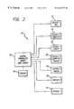
- FIG. 2is a block diagram showing the functional relationship between the central controller and a plurality of stations adapted to receive electrically powered devices.
- FIG. 3is a front perspective view of a stand-alone embodiment of the system for interactively, activating and monitoring the usage of selected computer and computer peripheral devices.
- FIG. 4is a rear perspective view of the system shown in FIG. 3 .
- FIG. 5shows the interactive user interface of the present invention.
- FIGS. 6A and 6Bshow an operational flowchart of a controller interface software module according to one embodiment of the present invention.
- FIGS. 7A and 7Bshow an electrical schematic of the communication link circuitry of one interactive electrical device selecting and activating system.
- FIG. 8shows an electrical schematic of the switching control circuitry of one interactive electrical device selecting and activating system.
- FIG. 9is a functional block diagram of an alternative embodiment of the system 30 .
- FIG. 10illustrates a system, in accordance with an alternative implementation of the present invention.
- FIG. 11is a block diagram illustrating one embodiment of a system for monitoring the status of and controlling one or more electrically powered devices.
- FIG. 12illustrates an exemplary power profile for a laser printer.
- FIG. 13is a flow diagram illustrating an exemplary process of the software module.
- FIG. 1shows an exemplary system 30 for interactively selecting and activating one or more electrically powered devices.
- the system 30includes one or more computers 40 and/or one or more computer peripheral devices (e.g., printer 42 ). While the exemplary system 30 includes computers, computer peripherals, and/or other devices typically found in an office, it is contemplated that the one or more electrically powered devices could include appliances such as, for example, a television or coffee maker.
- the system 30additionally includes a display 44 which comprises a video monitor as shown in this embodiment.
- the system 30may also include a mechanism for receiving payment, such as, for example, a card reader 46 for obtaining information from a credit card, pre-paid debit card, smart card, membership card, room key, or any other type of card.
- the mechanism for receiving paymentcan take another form such as a coin and/or currency receiving mechanism, a biometric recognition system linked to a database of personal or business accounts to verify characteristics of the user (e.g., fingerprint, retinal scan, voice recognition, etc.).
- a first key aspect of the present inventionis that the system 30 provides its users with a self-service means for selecting and activating particular groups of electrical devices from a plurality of electrical devices.
- One or several controllers and a switching mechanismare required to implement the system 30 .
- the display 44presents a sequence of menus which interactively prompt a user of the system 30 to provide user inputs which, for example, designate one or more (or a selected group of) devices from a computers 40 and computer peripheral devices 42 .
- At least one of the aforementioned controllersexecutes a computer executable program or programs for providing user interface control signals to the display 44 .
- the switching mechanismalso receives switching control signals generated by execution of a computer executable program by at least one of the controllers.
- a computer executable programis also employed to control a means for providing communication links between printer ports and a printer.
- the system 30may include additional computer executable programs providing communications interfaces to other computers, intelligent peripherals (e.g., payment receiving mechanisms), telecommunications hardware (e.g., telephones, facsimile machines).
- the system 30also includes interconnection hardware and the communications interfaces necessary for a user to “dock” a personal computer 32 or other electrically powered device to the system 30 .
- a controller or processor of the system 30controls a sequence of interactive visual menus presented at the display 44 thereby allowing the user to select and activate a group of electrically powered devices. More specifically, the user selects a group of “stations” (to which electrically powered devices may be, but are not necessarily, connected).
- a “station”is defined as a power outlet that the system 30 is capable of selecting and providing power to, combined with a communications interface that is controlled and accessible by a controller or processor of the system 30 .
- a usermay “dock” a notebook style personal computer 32 to the system 30 by selecting the appropriate station at the display 44 .
- the system 30executes software which applies power to the power outlets of the selected stations and enables the communications interface at the selected stations.
- the communications interface hardware at the stationscomprises connectors facilitating operable connection to currently favored computers and computer peripheral devices.
- the system 30may include redundant computer and computer peripheral devices so that more than one user can simultaneously create, activate and use “custom offices”. Accordingly, the system 30 intended to accommodate more than one user can have one or more display 44 .
- the software executed by the system 30monitors the availability of the computer and peripheral devices and provides a prospective user with an indication that a specified device is unavailable when no such device is currently available for use. As may be readily appreciated, various advanced features may be implemented including, but not limited to, allowing a prospective user to reserve the next available device of a presently unavailable type of electrically powered device.
- the system 30executes software which allows more than one user to make payment at the same time.
- the various electrically powered devicesmay be positioned in distinct areas separated by partition members 48 .
- the computer and computer peripheral devicesmay be segregated in a manner which anticipates typically selected combinations of office equipment.
- FIG. 2is a block diagram showing the functional relationship between a central controller 50 and a plurality of stations adapted to receive electrically powered devices.
- the central controller 50is functionally interconnected to a station 52 and is adapted to provide power and a communication link to a facsimile machine.
- the central controller 50provides power and communications interfaces to a station 54 which, for example, is adapted to receive a controller interface computer.
- a station 56is similarly controlled by the controller 50 which determines when power is made available to a copier and provides a communication link to the copier.
- a station 58can, for example, provide power and communications links to an electrically interconnected computer and printer which have been configured to be used together.
- a station 60is similarly configured to provide power and communications links to a modem. Additional stations such as stations 62 , 64 can also be included in the system 30 . The stations 62 , 64 allow other computer and computer peripheral devices to be docked to and used with the system 30 .
- the central controller 50additionally supports the system task of determining whether or not payment has been made by a prospective user of the system.
- the central controller 50receives inputs from a credit card reader.
- a printer 66is also electrically connected to the controller 50 .
- the printer 66may be designated as a dedicated printer which, for example, receives control signals from the central controller 50 and is only used to print receipts for payment or prepayment by the user.
- an additional printer(not shown), in addition to or in lieu of printer 66 , may be placed at a remote location such as a front desk or cashier's counter for printing receipts, statements, etc.
- the electrical connection between printer 66 and/or the second printer and the controller 50may be wired or wireless via radio frequency (“RF”) modules.
- RFradio frequency
- FIG. 9is a functional block diagram of an alternative embodiment of the system 30 .
- the controller 50provides user interface control signals to a touch screen display.
- the system 30also includes a switch box 68 which receives switching control signals from the controller 50 along control signal path 70 . It is contemplated that, in another embodiment, the switching control signals from the controller 50 to the switch box 68 may be wireless via RF modules.
- the system 30also includes a connection link switch box 72 which, for example, selectively provides communication links between one of the printer ports (of the controller 50 and the peripheral computer at station 58 ) and the peripheral printer at station 58 .
- the operational aspects of the switch boxes 68 , 72are discussed below in greater detail.
- the two switch boxes 68 , 72can be configured within a single switch box.
- the controller 50can also be adapted to support various telephonic data communication interfaces such as a charge-a-call phone line interface 74 , a coinless pay phone equivalent.
- the system 30may optionally include a printer 34 located at a secure, remote location such as a front desk of a hotel.
- a printer 34located at a secure, remote location such as a front desk of a hotel.
- a usermay use a room key having a magnetic strip to pay for usage of the system 30 , in which case the receipt will be printed at the front desk.
- the hotel personnelcan then add the cost of usage of the system 30 to the user's room bill.
- the remote printer 34may be located at a centralized location for billing members who use member cards. These connections made accomplished via wired or wireless methods.
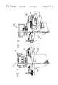
- FIG. 3is a front perspective view of a stand-alone embodiment of the system 30 .
- FIG. 4is a rear perspective view of the system shown in FIG. 3 .
- the stand-alone version of the systemincludes a pedestal unit 76 with a plurality of shelves 78 upon which computer peripheral devices are placed.
- the controller 50 and switch boxes 68 , 72can be physically positioned within the pedestal unit 76 or, alternatively, remotely located.
- Exemplary computer peripheral devicesinclude laser printers 80 and a facsimile machine 82 .
- the system 30includes a power strip 84 which is electrically connected to and controlled by the switch box 68 .
- the power strip 84may be positioned within the pedestal unit 76 or at some other location which is not readily accessible by users.
- the stand-alone unitis shown in a kiosk configuration, it should be appreciated that other types of furniture, equipment bays, etc., may be employed particularly if the computers and computer peripheral devices need to be more optimally secured to prevent their theft or attempts by users to manually override control signals from the controller 50 .
- the controller 50may be operated remotely via conventional networking schemes using the same interface methods. Conventional networking schemes include, for example, the MicrosoftTM WindowsTM network, Ethernet network, a dial-up modem (e.g., via telephone line), and the like.
- the controller 50may be operated remotely through the Internet.
- an interactive user interfaceis presented at the display 44 .
- a main menu display 86is first presented to a prospective user of the system 30 .
- the user interface control signalsinitiate a sequence of interactive displays.
- the interactive displaysinclude various fields providing information or facilitating user inputs.
- One means for receiving user inputsis a touch screen as shown in FIG. 5 .
- Information display fields 88can, for example, be employed to provide a prospective user with information about the cost per minute for using various computer and computer peripheral devices.
- An information icon 90initiates execution of computer executable programs which provide the user with information relevant to selected or indicated aspects of the system 30 .
- a help icon 92is presented to the user and initiates the execution of an executable program or programs which provide a user with additional information explaining how devices are selected, activated, prepayment is made, receipts obtained, etc.
- the available computer and computer peripheral devicesinclude a computer, printer, facsimile machine and copier. These electrically powered devices are respectively selected by pressing device selection icons 92 , 94 , 96 , 98 .
- the exemplary system 30may include other devices such as, for example, a scanner, fax/modem for access to the Internet, etc.
- the main menu screen 86additionally includes a device selection icon 100 which, when depressed by a user, initiates activation of a computer, printer, facsimile machine and copier as if all of the device selection icons 92 , 94 , 96 , 98 had been depressed.
- the main menu screen 86additionally includes credit card designation icons 102 which facilitate payment or prepayment by the user.
- FIGS. 6A and 6Bshow an operational flowchart of a controller interface software module according to one embodiment of the present invention.
- a main display menu executable block 110facilitates the display of currently entered user information, accrued charges and operational status information of the various computer and computer peripheral devices. Additionally, executable block 110 provides for the responsivity of portions of the touch screen for the purpose of selecting electrically powered devices for activation or deactivation.
- Executable block 112responds to user inputs. If the user provides an “activate equipment” input, the executable program is redirected toward executable block 114 . If the user provides a “deactivate equipment” input, the executable program is redirected toward executable program block 116 (FIG. 6 B). Additionally, a user may provide an “other functions” input. In response to such an input, the executable program is redirected toward executable program block 118 as shown in FIG. 6 A.
- the “other functions” menu block 118can be programmed to provide a variety of advertising displays, promotional offers and telephone and interconnect connections and services as well as on-line support features.
- the system 30is configured to operate as a self-service facility. As such, sufficient information must be provided to prospective users.
- execution of the “activate equipment” executable block 114is initiated, a brief video clip illustrating how a credit card is used to prepay is shown to the user.
- the controller interface computerrequests the user to input credit card information such as the account number and expiration date.
- the controller 50processes the next user input at executable block 120 which either receives the credit card information entered or cancels the transaction depending upon the user input. If the transaction is canceled, the executable program is redirected to the “main display menu” executable block 110 . If the user elects to continue with the transaction, the executable program is redirected to a “process credit card hold via modem” executable block 122 . At a “user input” executable block 124 , the user is given an opportunity to approve charging the transaction to the credit card after the transaction has been approved or to cancel the transaction. After a user approves a transaction, a “disclosure statement” executable block 126 controls the display of pertinent limitations and other information to the user.
- informationmay be provided to the user that a selected computer or computer peripheral device may only be reserved for up to one hour.
- Other displaysmay also be presented such as credit card terms and conditions and disclosures or other information that should or must (required by an applicable law or regulation) be presented to the user.
- the executable programis redirected to an executable program block 128 which controls the generation of control signals including switching control signals which are provided to the switch box 68 .
- the control signalsadditionally include communication link control signals which, for example, are provided to the switching box 72 to establish communication links between the various electrically powered devices.
- the executable block 128additionally monitors usage of the activated computer and computer peripheral devices. The usage is monitored so that the users are appropriately billed after the electrically controlled devices are deactivated and to assure that any predetermined usage limitations such as a maximum time duration are not exceeded.
- a “maximum duration exceeded” executable block 130displays a warning when the maximum duration has been exceeded and, in one embodiment, also displays an option to continue usage.
- a “user input” executable block 132redirects the executable program depending upon the user input provided. If the user provides an input indicating a desire to continue using the electrically powered devices, the user is prompted to verify previous inputs and/or provide additional user inputs and the activated devices remain activated or are reactivated as the case may be.
- the controller interface software modulecould also be programmed to provide users with options to add or delete various peripheral devices when a usage session comes to an end or prior to that time.
- the equipment usage monitoring featuremay result in the recordation of the exact amount of time any particular computer or computer peripheral device is activated, round to a nearest minimum time unit (e.g., 10 minutes) or simply bill a user for an amount of time no less than the amount of time reserved and no greater than the maximum amount of time allowed.
- a nearest minimum time unite.g. 10 minutes
- the executable programis redirected toward executable block 134 which generates the appropriate switching control signals to deactivate or disconnect power sources.
- the deactivated power sourcesare those which are connected to computer and computer peripheral equipment previously activated by the particular user who has failed to respond.
- the controller softwaremay be programmed to provide the user with a predetermined amount of time to respond (e.g., one minute) before power is removed from the equipment.
- a usage sessionis prepaid so that human system attendants are unnecessary.
- prepaymentmakes it convenient for a user to rapidly terminate a session and receive a receipt without having to wait for credit card approval, credit line verification or the like.
- the receiptis printed without account information to protect a user who is suddenly called away from a usage session.
- the executable programWhen a user provides a “deactivate equipment” input, the executable program is directed toward the executable block 116 as shown in FIG. 6 B. After the executable block 116 is initiated, the controller 50 calculates and sends control signals facilitating the display of updated charges. The user is also asked to confirm that deactivation is desired. After the user responds to the request for deactivation confirmation, an executable block 136 either confirms deactivation or cancels the request for deactivation and redirects the executable program such that device usage will continue.
- a “printing of receipt options” executable block 138is initiated.
- the executable block 138presents the user with the option of receiving a receipt with or without personal account information or, alternatively, the option of receiving no receipt.
- the user's responseis processed by a “user input” executable block 140 after which the executable program is redirected to an executable block 142 as shown in FIG. 13 .
- the executable block 142controls the printing of receipts; and thereafter sends control signals to remove power from the appropriate electrically powered devices via the switch box 68 .
- FIGS. 7A and 7Bshow an electrical schematic of communication link circuitry 150 of a system 30 .
- the communication link circuitry 150may be, but is not necessarily, located within the switch box 72 (FIG. 9 ). Generally the communication link circuitry 150 acts as a switch determining which of several communications ports is electrically connected to a peripheral device such as a printer. Referring again to FIG. 9, the controller 50 and the peripheral computer at station 58 both include printer ports. The peripheral printer at station 58 is connected to one of the aforementioned printer ports via the communication link circuitry 150 .
- Parallel printer port connections 152(FIG. 7A) and parallel printer port connections 154 (FIG.
- FIGS. 7A and 7Bare respectively connected to two different computers such as the controller 50 and the peripheral computer at station 58 via currently favored connection hardware, e.g., conventional 25-pin D-connectors.
- Parallel printer port connections 156(FIG. 7A) are connected, for example, to the peripheral printer at station 58 (FIG. 9 ).
- the unidirectional buffer circuitry 158may be replaced with bi-directional relay circuitry to facilitate bi-directional communications.
- protection circuitry 160may also be included.
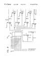
- FIG. 8shows an electrical schematic of switching control circuitry 170 according to one system 30 .
- Connections 172are electrically connected to a control port of the controller 50 .
- 8 bits of dataare provided to the connections 172 at a printer port of the controller 50 which has been programmed to function as a control port.
- the 8 bits of dataare provided to a data latch integrated circuit 174 which, for example, comprises a standard 74LS373 integrated circuit chip.
- the outputs of the data latch integrated circuit 174are provided to analog transistor circuitry 176 which provide inputs to relays (not shown) for controlling the activation and deactivation of the stations.
- the individual transistors 178comprise, for example, a conventional 2N2222 transistor. As shown in FIG. 8, light emitting diodes (“LEDs”) may be provided if desired.
- LEDslight emitting diodes
- FIG. 10illustrates a system 200 , in accordance with an alternative implementation of the present invention.
- the system 200interactively selects and activates key operating control lines of electrically powered devices (e.g., computer and computer peripheral devices) by maintaining or interrupting continuity of such control lines in addition to or in lieu of selecting and activating power to such devices.
- the system 200includes the touch screen controller 50 which controls the switch box 68 through control signals along control signal path 70 .
- the system 200further includes a computer 210 which is coupled to and/or controlled by an I/O device 212 through one or more key operating control lines 214 and 216 .
- a key operating control lineincludes a signal line which may be external or internal to an electrically powered device and controls the functionality of the device, either alone or in combination with other key operating control lines.
- the I/O device 212may be a keyboard with the key operating control line 216 being a power or communication line from the keyboard to the computer 210 .
- the key operating line 216couples the I/O device 212 to the computer 210 through an activator device 218 (e.g., a relay, combinational logic, etc.).
- the activator device 218is controlled by the switch box 68 via communication line 202 which selectively activates/deactivates the activator device 218 for maintaining or interrupting continuity of the key operating line 216 from the I/O device 212 to the computer 210 .
- the I/O device 212may be a mouse, monitor, modem or any other device used for controlling the computer 210 or a peripheral of the computer.
- at least one activator device 218may be coupled between a transmit and/or receive line between the computer 210 and a modem to maintain or interrupt continuity of an Internet session.
- the switch box 68may control more than one I/O device for a single electrically powered device such as a computer. For instance, if a session comes to an end and a user fails to respond, the controller 50 may control the switch box 68 to interrupt continuity of a keyboard, mouse, and/or monitor such that the user is precluded from controlling the computer 210 .
- the system 200controls a peripheral device 220 (e.g., a copier) via communication line 204 by activating/deactivating a control device (e.g., a relay) for maintaining or interrupting continuity of one or more key operating control lines of the peripheral device 220 .
- a control device 224is coupled between key operating control lines 226 and 228 of a counter (or “Auditron counter”) 222 . When activated, the control device 224 provides continuity between key operating control lines 226 and 228 which allows the peripheral device 220 to operate. When deactivated by the switch box 68 , the control device 224 interrupts continuity of key operating control lines 226 and 228 which prevents the peripheral device 220 from operating.
- a control device 234may be coupled between a sensor 232 and the input to a controller 236 .
- the control device 234may be controlled by the switch box 68 to mimic the sensor 232 .
- the sensor 232may be one of a number of key operating sensors of a copier, for example, such as a paper out, toner out, door cover ajar, or paper jam sensor, etc., all of which cause the copier to halt operation.
- the switch box 68deactivates the control device 234 to indicate to the microcontroller 236 via key operating control line 238 that there is a halt condition, thereby interrupting the operation of the peripheral device.
- the continuity of the peripheral devicecan be maintained or interrupted without cycling power on and off to such device.
- the advantage of controlling continuity of key operating control linesis that electrically powered devices do not have to be turned off and on.
- the switch box 68may control a vending machine 240 via communication lines 206 .
- the vending machine 240includes a plurality of motors 242 for controlling a corresponding plurality of coils 244 for dispensing various items.
- a transformermay optionally be placed in between each communication line 206 and each motor 242 in the case of a direct current motor.
- When a motor is activated by the switch box 68its corresponding coil initiates a predetermined cycle of rotation to dispense one item.
- the touch screen controller 50may execute a controller interface software module for providing a series of menus where a user can select one or more of a number of items from the vending machine 240 .
- the itemsmay include, for example, common “snacks”, office supplies (e.g., paper, pen, floppy disk, etc.), and the like.
- system 30 or the system 200may be used as a centralized system to control other types of electronically powered devices.
- the systemmay be implemented in a Laundromat for centrally controlling washing machines, dryers, etc., in a self-service car wash for centrally controlling car-wash stations, or in an arcade for centrally controlling video games, amusement games, etc.
- the system 200may be used to control the usage of software on a selected computer via controlling a software key (hereinafter referred to as a “Dongle”).
- a software keyhereinafter referred to as a “Dongle”.
- This mechanismallows a user to be charged on a per-software basis (e.g., for using a word processor, spread sheet program, etc.) rather than a per-computer basis. This can be accomplished, for example, by connecting a Dongle to an I/O port of the computer (e.g., printer port), placing an activator device (e.g., relay) in series with a key operating line of the Dongle, and controlling the relay by the switch box 68 .
- the controller 50may control usage of software programs by maintaining and/or interrupting continuity of the Dongle.
- a script programmay be written so that each application software program that is selected by the user first checks the status of a Dongle and, if the relay is activated by the switch box 68 (and the controller 50 ), indicating that the user has paid to use the software program, the software program executes properly and may be used by the user.
- a further aspect of the present inventionis an efficient and easy-to-implement method and apparatus for monitoring the status of and controlling such electronic devices.
- a special circuitis provided which provides measurement of the power (amperage) utilized by each electronic device.
- the power usage profile of each specific electronic devicecan be forwarded to the touch screen controller 50 .
- the power usage profilesare then analyzed by software running on the controller 50 to determine the operating status of the electronic device. This may be accomplished by using a standard database of power usage profiles to identify normal type operations and abnormal, catastrophic types of activity exhibited by the electronic devices.
- FIG. 11is a block diagram illustrating one embodiment of a system 300 for monitoring the status of and controlling one or more electrically powered devices.
- the system 300includes the touch screen controller 50 which is coupled to the switch box 68 by way of signal path 70 which may be an I/O port, parallel port, etc.
- the switch box 68is coupled to a relay 312 for activating and deactivating the same.
- the relay 312when activated, couples a power controller 318 (e.g., for supplying A/C power) to an electrically powered device 320 (e.g., computer, copier, fax, and any other electrically powered device).
- the device 320is coupled to the relay 312 through a current to voltage converter 314 .
- the current to voltage converter 314is an inductive ammeter.
- the current to voltage converters 314is also coupled to a channel of an analog to digital (“A/D”) converter 316 via signal line 315 .
- A/Danalog to digital
- the current to voltage converter 314when the relay 312 is activated by the switch box 68 , the current to voltage converter 314 outputs a voltage in the millivolt range that corresponds to the power output of the electrically powered devices 320 . It is contemplated that the system 300 includes a plurality of such relays and current to voltage converters for monitoring a corresponding plurality of electronically powered devices.
- the A/D converter 316is coupled to the controller 50 by way of signal path 305 (e.g., I/O port, parallel port, etc.).
- signal path 305e.g., I/O port, parallel port, etc.
- the device 320is on (i.e., by activating the relay 312 )
- the power usage of the deviceis transferred by the current to voltage converter 314 to the A/D converter 316 .
- the A/D converter 316converts the analog voltage into a digital stream and provides it to the controller 50 .
- the switch box 68 , relay 312 , current to voltage converter 314 , A/D converter 316 , and the power controller 318are all contained within an electronic switch box interface 310 .
- the A/D converter 316may be directly coupled to the bus of the controller 50 by way of, for example, a Peripheral Component Interconnect (“PCI”) form factor card.
- PCIPeripheral Component Interconnect
- the electrically powered devicesinclude, for example, a computer, copier, fax machine, laser printer, other types of peripheral devices, appliances (e.g., coffee maker, rice cooker, television, washing machine, etc.), and the like.
- the switch box 68may be replaced with a digital to analog (“D/A”) converter which is contained on the same board as the A/D converter 316 .
- D/Adigital to analog
- the controller 50includes a software module that provides the user interface for the operation and use of the system. In addition to recording user requests on the operation of the peripheral devices, the software module also determines the operating status and on/off control to the peripheral devices. The software module further allows the user to specify the time, duration, and conditions within which to turn on/off a selected electrically powered device. The conditions for on/off operations may include specific predetermined time and date, a temperature light sensor, by way of remote control via wireless or telephone access.
- the monitoring of the status of an electrically powered deviceis accomplished by recording and analyzing the digital output from the A/D converter 316 for a particular electrically powered device and comparing it to standard operating profiles for such device.
- a database of standard operating profilesrepresenting both regular operating profiles and abnormal/catastrophic (i.e., erroneous) operating profiles, may be maintained in a memory unit (not shown) of the controller 50 .
- the software modulecontinuously monitors the power profiles of the activated devices. If a device exhibits a power profile that represents a catastrophic/halt condition (i.e., a paper jam), the software module suspends charging a user for the time that such device is halted.
- a learning modeis provided so that the controller 50 can be adapted to monitoring new electrically powered devices which are plugged into the system.
- the learning processincludes establishing a baseline power consumption and typical operating conditions of the new electrically powered devices. More importantly, abnormal/catastrophic (i.e., erroneous) operating conditions are simulated and recorded onto the database. These power consumption profiles are the basis for the software module to determine the appropriate on/off state for the electrically powered device.
- the software moduleincludes a user interface which allows programming the on/off of the peripheral devices via user specified conditions.
- the software moduleincludes an algorithm which records power utilization profiles and makes comparisons with an established database of power utilization profiles.
- FIG. 12illustrates an exemplary power profile for a laser printer.
- the power profileshows time periods 410 where the laser printer is printing.
- the laser printeris in idle mode, as shown by the periodic spikes 425 .
- the laser printerhas a paper jam. During this unique period, the laser printer draws minimal power and has no significant spikes.
- the controller 50will detect a halt condition by comparing the stored profile in the database with the actual profile of the laser printer or by detecting that the power usage fails to rise above a predetermined threshold for a predetermined time period.
- FIG. 13is a flow diagram illustrating an exemplary process 500 of the software module.
- the process 500includes a learning mode and an operating mode (default).
- the processproceeds to block 504 where a power usage profile is established for the selected device.
- the power usage profileis a function of amperage and time.
- the power usage profile of the selected deviceincludes, for example, the power usage profile during normal operating conditions, abnormal conditions (e.g., paper jam), and catastrophic conditions.
- the power usage profile of the selected deviceis stored in a database.
- the processjumps back to block 502 , otherwise the process jumps to block 504 for establishing the power usage profile for another device.
- the process 500performs initialization at block 512 . Thereafter, at block 514 , the process 500 detects a valid method of payment (e.g., a credit card swipe), turns on an electrically powered device selected by the user, and initiates a billing timer. At block 516 a determination is made as to whether the user is done with the usage of the electrically powered device, e.g., by the user pressing an “END” button on a touch screen or the time period selected runs out. If the user is done, the process jumps to block 528 where the billing timer is stopped and power removed to the device or alternatively the continuity of a key operating control line is interrupted.
- a valid method of paymente.g., a credit card swipe
- the processproceeds to block 518 where the power usage is monitored and compared with the stored power usage profile of the device.
- the power usage profile of the deviceis determined. If the device is in normal operation, the process jumps back up to block 516 . If an abnormal condition is detected, the process proceeds to block 522 where billing is suspended and a warning message is displayed. Then, at block 524 the device is monitored and the billing timer is resumed when the device is back to normal condition. The process then jumps to block 516 . If at block 520 , a catastrophic condition is detected, then the process proceeds to block 526 where a warning message is displayed. The process continues to block 528 where the billing timer is stopped and the device is shut down.
- the monitoring of the power usage profile of an electrically powered deviceprovides the advantage of detecting an abnormal/catastrophic operation of the electrically powered device (e.g., when a copier has a paper jam) and automatically suspending billing for usage of that electrically powered device during such abnormal catastrophic condition.
Landscapes
- Engineering & Computer Science (AREA)
- Theoretical Computer Science (AREA)
- Business, Economics & Management (AREA)
- Physics & Mathematics (AREA)
- General Physics & Mathematics (AREA)
- General Engineering & Computer Science (AREA)
- Accounting & Taxation (AREA)
- Computer Hardware Design (AREA)
- Finance (AREA)
- Strategic Management (AREA)
- General Business, Economics & Management (AREA)
- Computer And Data Communications (AREA)
- Accessory Devices And Overall Control Thereof (AREA)
Abstract
Description
Claims (13)
Priority Applications (3)
| Application Number | Priority Date | Filing Date | Title |
|---|---|---|---|
| US09/088,213US6618772B1 (en) | 1996-11-15 | 1998-05-29 | Method and apparatus for selecting, monitoring, and controlling electrically powered devices |
| US09/707,647US7143204B1 (en) | 1996-11-15 | 2000-11-07 | Method and apparatus for suspending or adjusting billing charge for usage of electrically powered devices if abnormal or halt condition detected |
| US11/316,588US7277967B2 (en) | 1996-11-15 | 2005-12-22 | Method and apparatus for suspending or adjusting billing charge for usage of electrically powered devices if abnormal or halt condition detected |
Applications Claiming Priority (2)
| Application Number | Priority Date | Filing Date | Title |
|---|---|---|---|
| US08/749,905US5901067A (en) | 1996-11-15 | 1996-11-15 | System for interactively selecting and activating groups of electrically powered devices |
| US09/088,213US6618772B1 (en) | 1996-11-15 | 1998-05-29 | Method and apparatus for selecting, monitoring, and controlling electrically powered devices |
Related Parent Applications (1)
| Application Number | Title | Priority Date | Filing Date |
|---|---|---|---|
| US08/749,905Continuation-In-PartUS5901067A (en) | 1996-11-15 | 1996-11-15 | System for interactively selecting and activating groups of electrically powered devices |
Related Child Applications (1)
| Application Number | Title | Priority Date | Filing Date |
|---|---|---|---|
| US09/707,647DivisionUS7143204B1 (en) | 1996-11-15 | 2000-11-07 | Method and apparatus for suspending or adjusting billing charge for usage of electrically powered devices if abnormal or halt condition detected |
Publications (1)
| Publication Number | Publication Date |
|---|---|
| US6618772B1true US6618772B1 (en) | 2003-09-09 |
Family
ID=25015707
Family Applications (2)
| Application Number | Title | Priority Date | Filing Date |
|---|---|---|---|
| US08/749,905Expired - LifetimeUS5901067A (en) | 1996-11-15 | 1996-11-15 | System for interactively selecting and activating groups of electrically powered devices |
| US09/088,213Expired - Fee RelatedUS6618772B1 (en) | 1996-11-15 | 1998-05-29 | Method and apparatus for selecting, monitoring, and controlling electrically powered devices |
Family Applications Before (1)
| Application Number | Title | Priority Date | Filing Date |
|---|---|---|---|
| US08/749,905Expired - LifetimeUS5901067A (en) | 1996-11-15 | 1996-11-15 | System for interactively selecting and activating groups of electrically powered devices |
Country Status (3)
| Country | Link |
|---|---|
| US (2) | US5901067A (en) |
| AU (1) | AU7181398A (en) |
| WO (1) | WO1998021661A1 (en) |
Cited By (50)
| Publication number | Priority date | Publication date | Assignee | Title |
|---|---|---|---|---|
| US20020087350A1 (en)* | 2000-12-15 | 2002-07-04 | Tetsuya Miida | System, apparatus, and method for providing customer apparatus information, and apparatus for collecting and managing such information |
| US20020128853A1 (en)* | 2001-03-12 | 2002-09-12 | Hiroshige Kikuchi | Electric appliance renting system |
| US20020161831A1 (en)* | 2000-02-21 | 2002-10-31 | Yasushi Nakaoka | System for mediating printing on network |
| US20020173977A1 (en)* | 2001-05-17 | 2002-11-21 | International Business Machines Corporation | Charging for a computer based on actual usage time |
| US20020178128A1 (en)* | 2001-05-23 | 2002-11-28 | Steven Chen | System and method for providing payment-authorized printing services via the internet and via a stand alone device |
| US20030041016A1 (en)* | 2001-05-10 | 2003-02-27 | Spool Peter R. | Business management system and method for a deregulated electric power market using cooperatively produced estimates |
| US20030088523A1 (en)* | 2001-09-28 | 2003-05-08 | Sony Corporation | Electronic apparatus, time period charging system, time period charging method, and charging management system for electronic apparatus |
| US20030097335A1 (en)* | 2001-11-21 | 2003-05-22 | International Business Machines Corporation | Secure method and system for determining charges and assuring privacy |
| US20030127119A1 (en)* | 2002-01-09 | 2003-07-10 | Washing Equipment Technologies, Inc. | Operating system for vehicle washing bay |
| US20030208361A1 (en)* | 2002-05-02 | 2003-11-06 | Belinne Daryl Jarvis | Configuration of systems with services |
| US20030229683A1 (en)* | 2001-10-31 | 2003-12-11 | Sony Corporation | Information providing system and method and storage medium |
| US20040073432A1 (en)* | 2002-10-15 | 2004-04-15 | Stone Christopher J. | Webpad for the disabled |
| US20050004822A1 (en)* | 2001-03-28 | 2005-01-06 | Eric Elgrably | Method and data processing ssytem for timing the duration of a session |
| US20050135258A1 (en)* | 2003-12-22 | 2005-06-23 | Alan Amrod | Testing and emulating a device's power characteristics |
| WO2005003895A3 (en)* | 2003-06-26 | 2005-08-25 | Microsoft Corp | Interface for controlling access to computer objects |
| US20060020353A1 (en)* | 1999-12-30 | 2006-01-26 | Microsoft Corporation | Providing distributed scene programming of a home automation and control system |
| US20060200735A1 (en)* | 2004-07-20 | 2006-09-07 | Toshiba Corporation | System and method for providing fee-based data services to mobile users |
| US7330913B1 (en)* | 2002-02-11 | 2008-02-12 | Novell, Inc. | Method and apparatus for maintaining peripheral device support information |
| US20080040946A1 (en)* | 2006-08-15 | 2008-02-21 | American Dryer Corporation | Method of drying clothing with auto shut off and prorated billing |
| US20080120512A1 (en)* | 2006-11-20 | 2008-05-22 | Ricoh Corporation Ltd. | Remote wake-up from an energy-saving mode |
| US20080136607A1 (en)* | 2006-12-08 | 2008-06-12 | Liebert Corporation | User managed power system with security |
| US20080140813A1 (en)* | 2006-12-08 | 2008-06-12 | Liebert Corporation | Self-configuring ip addressable devices utilizing two ethernet protocol ip ports |
| US20080196171A1 (en)* | 2007-02-15 | 2008-08-21 | Lg Electronics Inc. | Commercial laundry system and method for controlling the same |
| US20080238404A1 (en)* | 2007-03-30 | 2008-10-02 | Liebert Corporation | Method and apparatus for monitoring a load |
| US20080265722A1 (en)* | 2007-04-26 | 2008-10-30 | Liebert Corporation | Intelligent track system for mounting electronic equipment |
| US20080281731A1 (en)* | 2001-03-30 | 2008-11-13 | Hisashi Takata | Customer support system, an office system, a customer support center, a supply center and a customer support method |
| US20090146494A1 (en)* | 2007-10-03 | 2009-06-11 | Belkin International, Inc. | Apparatus For Providing Electrical Power To Electrical Device And Method Of Use |
| US20090215319A1 (en)* | 2008-02-21 | 2009-08-27 | Hanoz Gandhi | Green Power Strip |
| US20100044195A1 (en)* | 2008-08-22 | 2010-02-25 | Primax Electronics Ltd. | Power strip device and method for controlling such power strip device |
| US20110166719A1 (en)* | 2010-01-05 | 2011-07-07 | Amperic Inc. | Monitoring Power Usage |
| US8138934B2 (en) | 2007-11-25 | 2012-03-20 | Trilliant Networks, Inc. | System and method for false alert filtering of event messages within a network |
| US8144596B2 (en) | 2007-11-25 | 2012-03-27 | Trilliant Networks, Inc. | Communication and message route optimization and messaging in a mesh network |
| GB2483932A (en)* | 2010-09-27 | 2012-03-28 | Buy As You View Ltd | System and method for controlling a device based upon usage and payments |
| US8171364B2 (en) | 2007-11-25 | 2012-05-01 | Trilliant Networks, Inc. | System and method for power outage and restoration notification in an advanced metering infrastructure network |
| US8289182B2 (en) | 2008-11-21 | 2012-10-16 | Trilliant Networks, Inc. | Methods and systems for virtual energy management display |
| US8319658B2 (en) | 2009-03-11 | 2012-11-27 | Trilliant Networks, Inc. | Process, device and system for mapping transformers to meters and locating non-technical line losses |
| US8332055B2 (en) | 2007-11-25 | 2012-12-11 | Trilliant Networks, Inc. | Energy use control system and method |
| US8334787B2 (en) | 2007-10-25 | 2012-12-18 | Trilliant Networks, Inc. | Gas meter having ultra-sensitive magnetic material retrofitted onto meter dial and method for performing meter retrofit |
| US8699377B2 (en) | 2008-09-04 | 2014-04-15 | Trilliant Networks, Inc. | System and method for implementing mesh network communications using a mesh network protocol |
| US8832428B2 (en) | 2010-11-15 | 2014-09-09 | Trilliant Holdings Inc. | System and method for securely communicating across multiple networks using a single radio |
| US8856323B2 (en) | 2011-02-10 | 2014-10-07 | Trilliant Holdings, Inc. | Device and method for facilitating secure communications over a cellular network |
| US8970394B2 (en) | 2011-01-25 | 2015-03-03 | Trilliant Holdings Inc. | Aggregated real-time power outages/restoration reporting (RTPOR) in a secure mesh network |
| US9001787B1 (en) | 2011-09-20 | 2015-04-07 | Trilliant Networks Inc. | System and method for implementing handover of a hybrid communications module |
| US9013173B2 (en) | 2010-09-13 | 2015-04-21 | Trilliant Networks, Inc. | Process for detecting energy theft |
| US9041349B2 (en) | 2011-03-08 | 2015-05-26 | Trilliant Networks, Inc. | System and method for managing load distribution across a power grid |
| US9084120B2 (en) | 2010-08-27 | 2015-07-14 | Trilliant Networks Inc. | System and method for interference free operation of co-located transceivers |
| US9282383B2 (en) | 2011-01-14 | 2016-03-08 | Trilliant Incorporated | Process, device and system for volt/VAR optimization |
| US9323831B2 (en) | 2010-09-28 | 2016-04-26 | International Business Machines Corporation | Providing answers to questions using hypothesis pruning |
| US9799018B2 (en) | 2011-03-08 | 2017-10-24 | D.Light Design, Inc. | Systems and methods for activation and deactivation of appliances |
| US20220188823A1 (en)* | 2019-10-21 | 2022-06-16 | Fujifilm Business Innovation Corp. | Information processing apparatus and non-transitory computer readable medium |
Families Citing this family (35)
| Publication number | Priority date | Publication date | Assignee | Title |
|---|---|---|---|---|
| US6804726B1 (en) | 1996-05-22 | 2004-10-12 | Geovector Corporation | Method and apparatus for controlling electrical devices in response to sensed conditions |
| US6822550B1 (en) | 1998-01-12 | 2004-11-23 | At Systems, Inc. | Intelligent rolled coin dispenser |
| US6087927A (en)* | 1998-01-30 | 2000-07-11 | Techknow, Inc. | Order communication system for restaurant |
| AU5910399A (en)* | 1998-09-11 | 2000-04-03 | Sharewave, Inc. | Method and apparatus for accessing a computer network communication channel |
| US7324544B1 (en) | 1998-09-11 | 2008-01-29 | Cirrus Logic, Inc. | Network slot synchronization scheme for a computer network communication channel |
| WO2000021807A1 (en)* | 1998-10-09 | 2000-04-20 | Autovend, Inc. | Cash management system interface |
| JP3723692B2 (en)* | 1999-01-26 | 2005-12-07 | 株式会社日立製作所 | Monitor device |
| JP3275871B2 (en)* | 1999-02-24 | 2002-04-22 | 日本電気株式会社 | Printer system and printer used therefor |
| US20040019560A1 (en) | 1999-03-12 | 2004-01-29 | Evans Scott L. | System and method for debt presentment and resolution |
| AU2003252917B2 (en)* | 1999-09-29 | 2006-12-21 | Canon Kabushiki Kaisha | Smart Card Systems and Electronic Ticketing Methods |
| US6910627B1 (en)* | 1999-09-29 | 2005-06-28 | Canon Kabushiki Kaisha | Smart card systems and electronic ticketing methods |
| US7124094B1 (en)* | 1999-10-27 | 2006-10-17 | Konica Corporation | Print system, service system, data server, master server, print client system and printer |
| AU3147001A (en)* | 2000-02-21 | 2001-09-03 | Logobject Ag | Method and installation for managing premises, especially for managing parking space |
| DE10039667A1 (en)* | 2000-08-14 | 2002-02-28 | Mettler Toledo Albstadt Gmbh | vending machine |
| AUPQ983500A0 (en)* | 2000-08-31 | 2000-09-28 | Canon Kabushiki Kaisha | Hyperlink access system |
| US6741442B1 (en) | 2000-10-13 | 2004-05-25 | American Power Conversion Corporation | Intelligent power distribution system |
| US7718889B2 (en)* | 2001-03-20 | 2010-05-18 | American Power Conversion Corporation | Adjustable scalable rack power system and method |
| US6992247B2 (en)* | 2002-01-02 | 2006-01-31 | American Power Conversion Corporation | Toolless mounting system and method for an adjustable scalable rack power system |
| US6967283B2 (en)* | 2001-03-20 | 2005-11-22 | American Power Conversion Corporation | Adjustable scalable rack power system and method |
| US7158938B2 (en)* | 2001-11-26 | 2007-01-02 | Xerox Corporation | User operated group machine time slot reservation and management system |
| US8788302B1 (en)* | 2002-03-20 | 2014-07-22 | Ncr Corporation | Method of controlling a self-service terminal |
| US7260730B2 (en)* | 2002-10-21 | 2007-08-21 | Canon Kabushiki Kaisha | Remote power configuration of functions within multifunction apparatus using status and setting screens displayed on external apparatus |
| WO2006034443A1 (en)* | 2004-09-20 | 2006-03-30 | American Power Conversion Corporation | Equipment rack data/power distribution |
| US20060064310A1 (en)* | 2004-09-21 | 2006-03-23 | Crystal Image Artwurks Corp. | Tattoo studio control and management system |
| US20060072269A1 (en)* | 2004-09-30 | 2006-04-06 | Staples Peter E | Amperage apparatus for displaying ralative amperage load |
| US7580146B2 (en)* | 2005-03-22 | 2009-08-25 | Xerox Corporation | Hierarchical architecture for a distributed and scalable network printing system |
| US7606014B2 (en)* | 2006-06-16 | 2009-10-20 | American Power Conversion Corporation | Apparatus and method for scalable power distribution |
| US7619868B2 (en)* | 2006-06-16 | 2009-11-17 | American Power Conversion Corporation | Apparatus and method for scalable power distribution |
| US8660941B2 (en)* | 2006-09-26 | 2014-02-25 | Collections Marketing Center, Inc. | Method and system for providing a multi-channel virtual collections center |
| US7940504B2 (en)* | 2007-06-21 | 2011-05-10 | American Power Conversion Corporation | Apparatus and method for scalable power distribution |
| JP2009225139A (en)* | 2008-03-17 | 2009-10-01 | Brother Ind Ltd | Image processing apparatus |
| US20100010861A1 (en)* | 2008-07-11 | 2010-01-14 | Collections Marketing Center, Llc | Method and system for providing a virtual collections call center system |
| US8212427B2 (en) | 2009-12-03 | 2012-07-03 | American Power Converison Corporation | Apparatus and method for scalable power distribution |
| US20110167187A1 (en)* | 2010-01-06 | 2011-07-07 | Apple Inc. | Connectors in a portable device |
| US8510170B2 (en)* | 2010-12-22 | 2013-08-13 | Toshiba Global Commerce Solutions Holdings Corporation | Powering a point of sale printer and coupon printer from a shared power supply |
Citations (66)
| Publication number | Priority date | Publication date | Assignee | Title |
|---|---|---|---|---|
| US3705384A (en) | 1971-08-10 | 1972-12-05 | Eric C Wahlberg | Business transaction apparatus |
| US3803491A (en)* | 1971-05-26 | 1974-04-09 | Tocom | Communications system |
| US3828325A (en)* | 1973-02-05 | 1974-08-06 | Honeywell Inf Systems | Universal interface system using a controller to adapt to any connecting peripheral device |
| US4053720A (en)* | 1975-12-02 | 1977-10-11 | International Telephone And Telegraph Corporation | Automatic exclusion circuit |
| US4306293A (en)* | 1979-08-30 | 1981-12-15 | Marathe Sharad M | Energy monitoring system |
| US4312035A (en) | 1979-06-18 | 1982-01-19 | Greene Richard E | Apparatus for controlling electrical power in a data processing system |
| US4386400A (en)* | 1977-12-15 | 1983-05-31 | International Business Machines Corp. | Reset of a selected I/O channel and associated peripheral equipment by means independent of the channel |
| US4413211A (en)* | 1981-12-23 | 1983-11-01 | Fowler Ricky C | Control circuit for electrical appliances |
| US4465956A (en)* | 1983-02-25 | 1984-08-14 | Fowler Ricky C | Control circuit for switching dual function electrical appliances |
| US4481590A (en)* | 1980-06-16 | 1984-11-06 | Pepsico Incorporated | Vending machine control circuit |
| US4567359A (en) | 1984-05-24 | 1986-01-28 | Lockwood Lawrence B | Automatic information, goods and services dispensing system |
| US4583682A (en)* | 1984-03-22 | 1986-04-22 | Florida Energy Control Corp. | Air conditioning monitoring device |
| US4593361A (en)* | 1980-06-16 | 1986-06-03 | Pepsico Inc. | Vending machine control circuit |
| US4598378A (en)* | 1983-02-07 | 1986-07-01 | H.R. Electronics Company | Management information system and associated vending control device |
| US4624578A (en) | 1985-12-02 | 1986-11-25 | Green David L | Rental contract timer system |
| US4639876A (en)* | 1984-10-22 | 1987-01-27 | Deeds Robert G | Multi-unit energy use monitor |
| US4650978A (en)* | 1985-01-23 | 1987-03-17 | Rmh Systems, Inc. | Off line cash card system and method |
| US4700296A (en) | 1985-04-19 | 1987-10-13 | Palmer Jr Roy A | Electronic access control system |
| US4703412A (en) | 1985-09-13 | 1987-10-27 | Lee Colortran, Inc. | Portable control unit for theater, television, and film lighting control systems |
| US4783747A (en)* | 1986-03-04 | 1988-11-08 | Sanden Corporation | Control device for an automatic vending machine |
| US4808841A (en) | 1986-11-12 | 1989-02-28 | Hitachi, Ltd. | Centralized control system for home electric appliances |
| US4831242A (en) | 1985-09-12 | 1989-05-16 | Bally Manufacturing Corporation | Control system for health club facilities and equipment |
| US4902881A (en) | 1988-06-10 | 1990-02-20 | Faxplus Corporation | Parallel process communications terminal and network |
| US4947028A (en) | 1988-07-19 | 1990-08-07 | Arbor International, Inc. | Automated order and payment system |
| US5066853A (en) | 1987-09-21 | 1991-11-19 | Sgs Thomson Microelectronics Sa | System for reserving a supply of goods or services |
| US5113351A (en) | 1989-03-29 | 1992-05-12 | Delphi Technology, Inc. | Automated, interactive vending system for products which must be processed |
| US5157273A (en) | 1990-06-08 | 1992-10-20 | Donnelly Corporation | Modular power outlet strip |
| US5162989A (en) | 1987-02-20 | 1992-11-10 | Oki Electric Industry Co., Ltd. | Information rental system including processor equipped IC card having data erasing means |
| US5163124A (en) | 1987-10-14 | 1992-11-10 | Sharp Kabushiki Kaisha | Method and apparatus for controlling power to device in a computer system |
| US5164609A (en) | 1990-06-08 | 1992-11-17 | Donnelly Corporation | Controllable power distribution system |
| US5187352A (en)* | 1989-01-03 | 1993-02-16 | William Blair | Microprocessor controlled security system for computers |
| US5198806A (en) | 1990-12-31 | 1993-03-30 | Lord & Sebastian, Inc. | Remote control and secure access for personal computers |
| US5206488A (en) | 1989-06-07 | 1993-04-27 | Mordechai Teicher | Credit card system including a central unit and a plurality of local units for conducting low-cost transactions |
| US5207784A (en)* | 1989-03-09 | 1993-05-04 | Wilbur Schwartzendruber | Vending machine with monitoring system |
| US5278771A (en) | 1991-07-12 | 1994-01-11 | Seti Corporation | Programmable timed electrical power management device |
| US5301122A (en) | 1992-02-12 | 1994-04-05 | Measuring And Monitoring, Inc. | Measuring and monitoring system |
| US5347167A (en) | 1990-08-09 | 1994-09-13 | Sophisticated Circuits, Inc. | Power controller using keyboard and computer interface |
| US5359540A (en) | 1990-07-23 | 1994-10-25 | Hugo Ortiz | Computer assisted electric power management |
| US5369740A (en) | 1991-09-12 | 1994-11-29 | Emerson Electric Co. | Versatile programmable electronic controller |
| US5393964A (en) | 1990-10-12 | 1995-02-28 | Tpi, Inc. | Telecommunications booth and method of use |
| US5396417A (en) | 1991-11-01 | 1995-03-07 | Capitol Cities/Abc, Inc. | Product distribution equipment and method |
| US5396443A (en)* | 1992-10-07 | 1995-03-07 | Hitachi, Ltd. | Information processing apparatus including arrangements for activation to and deactivation from a power-saving state |
| US5412189A (en) | 1992-12-21 | 1995-05-02 | International Business Machines Corporation | Touch screen apparatus with tactile information |
| US5424940A (en)* | 1988-04-25 | 1995-06-13 | Ousborne; Jeffrey J. | Computer controlled system providing functions within a laundromat facility |
| US5440108A (en) | 1991-10-11 | 1995-08-08 | Verifone, Inc. | System and method for dispensing and revalung cash cards |
| US5451755A (en) | 1992-10-06 | 1995-09-19 | Electricite De France (Edf) | Self-contained device for self-service delivery of electrical energy |
| US5483656A (en) | 1993-01-14 | 1996-01-09 | Apple Computer, Inc. | System for managing power consumption of devices coupled to a common bus |
| US5491326A (en) | 1994-11-23 | 1996-02-13 | Xcp, Inc. | Card metering system |
| US5499707A (en) | 1995-01-31 | 1996-03-19 | Compu-Shop, Inc. | Automated merchandising kiosk |
| US5506790A (en) | 1992-01-15 | 1996-04-09 | Nguyen; Sanh K. | Single-chip microcomputer programmable power distributor |
| US5544138A (en) | 1993-12-30 | 1996-08-06 | International Business Machines Corporation | Adaptive system for optimizing disk drive power consumption |
| US5572438A (en) | 1995-01-05 | 1996-11-05 | Teco Energy Management Services | Engery management and building automation system |
| US5590382A (en)* | 1993-03-15 | 1996-12-31 | Elonex Ip Holdings Ltd. | Personal digital assistant module having a multi-portion keyboard with inductive coupling |
| US5615105A (en) | 1994-07-07 | 1997-03-25 | Leach Corporation | Multichannel power distribution system |
| US5619024A (en)* | 1994-12-12 | 1997-04-08 | Usa Technologies, Inc. | Credit card and bank issued debit card operated system and method for controlling and monitoring access of computer and copy equipment |
| US5625669A (en)* | 1991-09-27 | 1997-04-29 | Telemac Cellular Corporation | Mobile phone with internal call accounting controls |
| US5652892A (en) | 1993-10-20 | 1997-07-29 | Hitachi, Ltd. | Method and apparatus for controlling remote power source |
| USH1708H (en)* | 1991-04-02 | 1998-02-03 | Creatacard, Inc. | System for creating and producing custom card products |
| US5793629A (en)* | 1994-05-13 | 1998-08-11 | Kabushiki Kaisha Nippon Conlux | Distributed processing unit |
| US5799281A (en)* | 1996-01-23 | 1998-08-25 | E.L.M.S., Llc | Computer control and management system for laundry installation |
| US5799068A (en)* | 1992-06-29 | 1998-08-25 | Elonex I.P. Holdings Ltd. | Smart phone integration with computer systems |
| US5802389A (en)* | 1994-12-29 | 1998-09-01 | Siemens Energy & Automation, Inc. | Expansion module address method and apparatus for a programmable logic controller |
| US5812643A (en)* | 1997-02-06 | 1998-09-22 | Powertel, Inc. | Power and telecommunications access vending machine |
| US5845256A (en)* | 1993-08-19 | 1998-12-01 | John B. Pescitelli | Interactive self-service vending system |
| US5898232A (en) | 1995-11-08 | 1999-04-27 | Advanced Micro Devices, Inc. | Input/output section of an integrated circuit having separate power down capability |
| US5925115A (en)* | 1997-03-10 | 1999-07-20 | Vlsi Technology, Inc. | Method and system for extending interrupt sources and implementing hardware based and software based prioritization of interrupts for an embedded processor |
- 1996
- 1996-11-15USUS08/749,905patent/US5901067A/ennot_activeExpired - Lifetime
- 1997
- 1997-11-11AUAU71813/98Apatent/AU7181398A/ennot_activeAbandoned
- 1997-11-11WOPCT/US1997/020198patent/WO1998021661A1/enactiveApplication Filing
- 1998
- 1998-05-29USUS09/088,213patent/US6618772B1/ennot_activeExpired - Fee Related
Patent Citations (67)
| Publication number | Priority date | Publication date | Assignee | Title |
|---|---|---|---|---|
| US3803491A (en)* | 1971-05-26 | 1974-04-09 | Tocom | Communications system |
| US3705384A (en) | 1971-08-10 | 1972-12-05 | Eric C Wahlberg | Business transaction apparatus |
| US3828325A (en)* | 1973-02-05 | 1974-08-06 | Honeywell Inf Systems | Universal interface system using a controller to adapt to any connecting peripheral device |
| US4053720A (en)* | 1975-12-02 | 1977-10-11 | International Telephone And Telegraph Corporation | Automatic exclusion circuit |
| US4386400A (en)* | 1977-12-15 | 1983-05-31 | International Business Machines Corp. | Reset of a selected I/O channel and associated peripheral equipment by means independent of the channel |
| US4312035A (en) | 1979-06-18 | 1982-01-19 | Greene Richard E | Apparatus for controlling electrical power in a data processing system |
| US4306293A (en)* | 1979-08-30 | 1981-12-15 | Marathe Sharad M | Energy monitoring system |
| US4481590A (en)* | 1980-06-16 | 1984-11-06 | Pepsico Incorporated | Vending machine control circuit |
| US4593361A (en)* | 1980-06-16 | 1986-06-03 | Pepsico Inc. | Vending machine control circuit |
| US4413211A (en)* | 1981-12-23 | 1983-11-01 | Fowler Ricky C | Control circuit for electrical appliances |
| US4598378A (en)* | 1983-02-07 | 1986-07-01 | H.R. Electronics Company | Management information system and associated vending control device |
| US4465956A (en)* | 1983-02-25 | 1984-08-14 | Fowler Ricky C | Control circuit for switching dual function electrical appliances |
| US4583682A (en)* | 1984-03-22 | 1986-04-22 | Florida Energy Control Corp. | Air conditioning monitoring device |
| US4567359A (en) | 1984-05-24 | 1986-01-28 | Lockwood Lawrence B | Automatic information, goods and services dispensing system |
| US4639876A (en)* | 1984-10-22 | 1987-01-27 | Deeds Robert G | Multi-unit energy use monitor |
| US4650978A (en)* | 1985-01-23 | 1987-03-17 | Rmh Systems, Inc. | Off line cash card system and method |
| US4700296A (en) | 1985-04-19 | 1987-10-13 | Palmer Jr Roy A | Electronic access control system |
| US4831242A (en) | 1985-09-12 | 1989-05-16 | Bally Manufacturing Corporation | Control system for health club facilities and equipment |
| US4703412A (en) | 1985-09-13 | 1987-10-27 | Lee Colortran, Inc. | Portable control unit for theater, television, and film lighting control systems |
| US4624578A (en) | 1985-12-02 | 1986-11-25 | Green David L | Rental contract timer system |
| US4783747A (en)* | 1986-03-04 | 1988-11-08 | Sanden Corporation | Control device for an automatic vending machine |
| US4808841A (en) | 1986-11-12 | 1989-02-28 | Hitachi, Ltd. | Centralized control system for home electric appliances |
| US5162989A (en) | 1987-02-20 | 1992-11-10 | Oki Electric Industry Co., Ltd. | Information rental system including processor equipped IC card having data erasing means |
| US5066853A (en) | 1987-09-21 | 1991-11-19 | Sgs Thomson Microelectronics Sa | System for reserving a supply of goods or services |
| US5163124A (en) | 1987-10-14 | 1992-11-10 | Sharp Kabushiki Kaisha | Method and apparatus for controlling power to device in a computer system |
| US5424940A (en)* | 1988-04-25 | 1995-06-13 | Ousborne; Jeffrey J. | Computer controlled system providing functions within a laundromat facility |
| US4902881A (en) | 1988-06-10 | 1990-02-20 | Faxplus Corporation | Parallel process communications terminal and network |
| US4947028A (en) | 1988-07-19 | 1990-08-07 | Arbor International, Inc. | Automated order and payment system |
| US4947028B1 (en) | 1988-07-19 | 1993-06-08 | U S Order Inc | |
| US5187352A (en)* | 1989-01-03 | 1993-02-16 | William Blair | Microprocessor controlled security system for computers |
| US5207784A (en)* | 1989-03-09 | 1993-05-04 | Wilbur Schwartzendruber | Vending machine with monitoring system |
| US5113351A (en) | 1989-03-29 | 1992-05-12 | Delphi Technology, Inc. | Automated, interactive vending system for products which must be processed |
| US5206488A (en) | 1989-06-07 | 1993-04-27 | Mordechai Teicher | Credit card system including a central unit and a plurality of local units for conducting low-cost transactions |
| US5164609A (en) | 1990-06-08 | 1992-11-17 | Donnelly Corporation | Controllable power distribution system |
| US5157273A (en) | 1990-06-08 | 1992-10-20 | Donnelly Corporation | Modular power outlet strip |
| US5359540A (en) | 1990-07-23 | 1994-10-25 | Hugo Ortiz | Computer assisted electric power management |
| US5347167A (en) | 1990-08-09 | 1994-09-13 | Sophisticated Circuits, Inc. | Power controller using keyboard and computer interface |
| US5393964A (en) | 1990-10-12 | 1995-02-28 | Tpi, Inc. | Telecommunications booth and method of use |
| US5198806A (en) | 1990-12-31 | 1993-03-30 | Lord & Sebastian, Inc. | Remote control and secure access for personal computers |
| USH1708H (en)* | 1991-04-02 | 1998-02-03 | Creatacard, Inc. | System for creating and producing custom card products |
| US5278771A (en) | 1991-07-12 | 1994-01-11 | Seti Corporation | Programmable timed electrical power management device |
| US5369740A (en) | 1991-09-12 | 1994-11-29 | Emerson Electric Co. | Versatile programmable electronic controller |
| US5625669A (en)* | 1991-09-27 | 1997-04-29 | Telemac Cellular Corporation | Mobile phone with internal call accounting controls |
| US5440108A (en) | 1991-10-11 | 1995-08-08 | Verifone, Inc. | System and method for dispensing and revalung cash cards |
| US5396417A (en) | 1991-11-01 | 1995-03-07 | Capitol Cities/Abc, Inc. | Product distribution equipment and method |
| US5506790A (en) | 1992-01-15 | 1996-04-09 | Nguyen; Sanh K. | Single-chip microcomputer programmable power distributor |
| US5301122A (en) | 1992-02-12 | 1994-04-05 | Measuring And Monitoring, Inc. | Measuring and monitoring system |
| US5799068A (en)* | 1992-06-29 | 1998-08-25 | Elonex I.P. Holdings Ltd. | Smart phone integration with computer systems |
| US5451755A (en) | 1992-10-06 | 1995-09-19 | Electricite De France (Edf) | Self-contained device for self-service delivery of electrical energy |
| US5396443A (en)* | 1992-10-07 | 1995-03-07 | Hitachi, Ltd. | Information processing apparatus including arrangements for activation to and deactivation from a power-saving state |
| US5412189A (en) | 1992-12-21 | 1995-05-02 | International Business Machines Corporation | Touch screen apparatus with tactile information |
| US5483656A (en) | 1993-01-14 | 1996-01-09 | Apple Computer, Inc. | System for managing power consumption of devices coupled to a common bus |
| US5590382A (en)* | 1993-03-15 | 1996-12-31 | Elonex Ip Holdings Ltd. | Personal digital assistant module having a multi-portion keyboard with inductive coupling |
| US5845256A (en)* | 1993-08-19 | 1998-12-01 | John B. Pescitelli | Interactive self-service vending system |
| US5652892A (en) | 1993-10-20 | 1997-07-29 | Hitachi, Ltd. | Method and apparatus for controlling remote power source |
| US5544138A (en) | 1993-12-30 | 1996-08-06 | International Business Machines Corporation | Adaptive system for optimizing disk drive power consumption |
| US5793629A (en)* | 1994-05-13 | 1998-08-11 | Kabushiki Kaisha Nippon Conlux | Distributed processing unit |
| US5615105A (en) | 1994-07-07 | 1997-03-25 | Leach Corporation | Multichannel power distribution system |
| US5491326A (en) | 1994-11-23 | 1996-02-13 | Xcp, Inc. | Card metering system |
| US5619024A (en)* | 1994-12-12 | 1997-04-08 | Usa Technologies, Inc. | Credit card and bank issued debit card operated system and method for controlling and monitoring access of computer and copy equipment |
| US5802389A (en)* | 1994-12-29 | 1998-09-01 | Siemens Energy & Automation, Inc. | Expansion module address method and apparatus for a programmable logic controller |
| US5572438A (en) | 1995-01-05 | 1996-11-05 | Teco Energy Management Services | Engery management and building automation system |
| US5499707A (en) | 1995-01-31 | 1996-03-19 | Compu-Shop, Inc. | Automated merchandising kiosk |
| US5898232A (en) | 1995-11-08 | 1999-04-27 | Advanced Micro Devices, Inc. | Input/output section of an integrated circuit having separate power down capability |
| US5799281A (en)* | 1996-01-23 | 1998-08-25 | E.L.M.S., Llc | Computer control and management system for laundry installation |
| US5812643A (en)* | 1997-02-06 | 1998-09-22 | Powertel, Inc. | Power and telecommunications access vending machine |
| US5925115A (en)* | 1997-03-10 | 1999-07-20 | Vlsi Technology, Inc. | Method and system for extending interrupt sources and implementing hardware based and software based prioritization of interrupts for an embedded processor |
Cited By (77)
| Publication number | Priority date | Publication date | Assignee | Title |
|---|---|---|---|---|
| US7099723B2 (en)* | 1999-12-30 | 2006-08-29 | Microsoft Corporation | Providing distributed scene programming of a home automation and control system |
| US20060020353A1 (en)* | 1999-12-30 | 2006-01-26 | Microsoft Corporation | Providing distributed scene programming of a home automation and control system |
| US20020161831A1 (en)* | 2000-02-21 | 2002-10-31 | Yasushi Nakaoka | System for mediating printing on network |
| US7370090B2 (en) | 2000-02-21 | 2008-05-06 | Seiko Epson Corporation | Print portal system on network |
| US7266590B2 (en)* | 2000-02-21 | 2007-09-04 | Seiko Epson Corporation | System for mediating printing on network |
| US20070027990A1 (en)* | 2000-02-21 | 2007-02-01 | Seiko Epson Corporation | Print portal system on network |
| US20050251412A1 (en)* | 2000-12-15 | 2005-11-10 | Tetsuya Miida | System, apparatus, and method for providing customer apparatus information, and apparatus for collecting and managing such information |
| US20020087350A1 (en)* | 2000-12-15 | 2002-07-04 | Tetsuya Miida | System, apparatus, and method for providing customer apparatus information, and apparatus for collecting and managing such information |
| US20020128853A1 (en)* | 2001-03-12 | 2002-09-12 | Hiroshige Kikuchi | Electric appliance renting system |
| US20050004822A1 (en)* | 2001-03-28 | 2005-01-06 | Eric Elgrably | Method and data processing ssytem for timing the duration of a session |
| US20080281731A1 (en)* | 2001-03-30 | 2008-11-13 | Hisashi Takata | Customer support system, an office system, a customer support center, a supply center and a customer support method |
| US20030041016A1 (en)* | 2001-05-10 | 2003-02-27 | Spool Peter R. | Business management system and method for a deregulated electric power market using cooperatively produced estimates |
| US20020173977A1 (en)* | 2001-05-17 | 2002-11-21 | International Business Machines Corporation | Charging for a computer based on actual usage time |
| US20020178128A1 (en)* | 2001-05-23 | 2002-11-28 | Steven Chen | System and method for providing payment-authorized printing services via the internet and via a stand alone device |
| US7577571B2 (en)* | 2001-09-28 | 2009-08-18 | Yasuji Yui | Electronic apparatus, time period charging system, time period charging method, and charging management system for electronic apparatus |
| US20030088523A1 (en)* | 2001-09-28 | 2003-05-08 | Sony Corporation | Electronic apparatus, time period charging system, time period charging method, and charging management system for electronic apparatus |
| US20090055750A1 (en)* | 2001-10-31 | 2009-02-26 | Sony Corporation | Information providing system and method and storage medium |
| US8335928B2 (en) | 2001-10-31 | 2012-12-18 | Sony Corporation | Information providing system and method and storage medium |
| US7458026B2 (en)* | 2001-10-31 | 2008-11-25 | Sony Corporation | Information providing system and method and storage medium |
| US20030229683A1 (en)* | 2001-10-31 | 2003-12-11 | Sony Corporation | Information providing system and method and storage medium |
| US20030097335A1 (en)* | 2001-11-21 | 2003-05-22 | International Business Machines Corporation | Secure method and system for determining charges and assuring privacy |
| US20030127119A1 (en)* | 2002-01-09 | 2003-07-10 | Washing Equipment Technologies, Inc. | Operating system for vehicle washing bay |
| US7330913B1 (en)* | 2002-02-11 | 2008-02-12 | Novell, Inc. | Method and apparatus for maintaining peripheral device support information |
| US20030208361A1 (en)* | 2002-05-02 | 2003-11-06 | Belinne Daryl Jarvis | Configuration of systems with services |
| US20040073432A1 (en)* | 2002-10-15 | 2004-04-15 | Stone Christopher J. | Webpad for the disabled |
| WO2005003895A3 (en)* | 2003-06-26 | 2005-08-25 | Microsoft Corp | Interface for controlling access to computer objects |
| US7162377B2 (en)* | 2003-12-22 | 2007-01-09 | Ixia | Testing and emulating a device's power characteristics |
| US20050135258A1 (en)* | 2003-12-22 | 2005-06-23 | Alan Amrod | Testing and emulating a device's power characteristics |
| US7730393B2 (en)* | 2004-07-20 | 2010-06-01 | Toshiba Corporation | System and method for providing fee-based data services to mobile users |
| US20060200735A1 (en)* | 2004-07-20 | 2006-09-07 | Toshiba Corporation | System and method for providing fee-based data services to mobile users |
| US20080040946A1 (en)* | 2006-08-15 | 2008-02-21 | American Dryer Corporation | Method of drying clothing with auto shut off and prorated billing |
| US20100083528A1 (en)* | 2006-08-15 | 2010-04-08 | American Dryer Corp. | Method of drying clothing with auto shut off and prorated billing |
| WO2008022111A3 (en)* | 2006-08-15 | 2008-12-18 | American Dryer Corp | Method of drying clothing with auto shut off and prorated billing |
| US20080120512A1 (en)* | 2006-11-20 | 2008-05-22 | Ricoh Corporation Ltd. | Remote wake-up from an energy-saving mode |
| US7730339B2 (en)* | 2006-11-20 | 2010-06-01 | Ricoh Company, Ltd. | Remote wake-up from an energy-saving mode |
| US8450874B2 (en) | 2006-12-08 | 2013-05-28 | Liebert Corporation | User managed power system with security |
| US20080140813A1 (en)* | 2006-12-08 | 2008-06-12 | Liebert Corporation | Self-configuring ip addressable devices utilizing two ethernet protocol ip ports |
| US20080136607A1 (en)* | 2006-12-08 | 2008-06-12 | Liebert Corporation | User managed power system with security |
| US7860955B2 (en) | 2006-12-08 | 2010-12-28 | Liebert Corporation | Self-configuring IP addressable devices utilizing two ethernet protocol IP ports |
| US20110035471A1 (en)* | 2006-12-08 | 2011-02-10 | Liebert Corporation | Self-configuring ip addressable devices utilizing two ethernet protocol ip ports |
| US7987248B2 (en) | 2006-12-08 | 2011-07-26 | Liebert Corporation | Self-configuring IP addressable devices utilizing two ethernet protocol IP ports |
| US20080196171A1 (en)* | 2007-02-15 | 2008-08-21 | Lg Electronics Inc. | Commercial laundry system and method for controlling the same |
| US7950087B2 (en)* | 2007-02-15 | 2011-05-31 | Lg Electronics Inc. | Commercial laundry system and method for controlling the same |
| US20080238404A1 (en)* | 2007-03-30 | 2008-10-02 | Liebert Corporation | Method and apparatus for monitoring a load |
| US7969156B2 (en) | 2007-03-30 | 2011-06-28 | Liebert Corporation | Method and apparatus for monitoring a load |
| US20080265722A1 (en)* | 2007-04-26 | 2008-10-30 | Liebert Corporation | Intelligent track system for mounting electronic equipment |
| US7857214B2 (en) | 2007-04-26 | 2010-12-28 | Liebert Corporation | Intelligent track system for mounting electronic equipment |
| US20090146494A1 (en)* | 2007-10-03 | 2009-06-11 | Belkin International, Inc. | Apparatus For Providing Electrical Power To Electrical Device And Method Of Use |
| US8334787B2 (en) | 2007-10-25 | 2012-12-18 | Trilliant Networks, Inc. | Gas meter having ultra-sensitive magnetic material retrofitted onto meter dial and method for performing meter retrofit |
| US8332055B2 (en) | 2007-11-25 | 2012-12-11 | Trilliant Networks, Inc. | Energy use control system and method |
| US8144596B2 (en) | 2007-11-25 | 2012-03-27 | Trilliant Networks, Inc. | Communication and message route optimization and messaging in a mesh network |
| US8171364B2 (en) | 2007-11-25 | 2012-05-01 | Trilliant Networks, Inc. | System and method for power outage and restoration notification in an advanced metering infrastructure network |
| US8725274B2 (en) | 2007-11-25 | 2014-05-13 | Trilliant Networks, Inc. | Energy use control system and method |
| US8138934B2 (en) | 2007-11-25 | 2012-03-20 | Trilliant Networks, Inc. | System and method for false alert filtering of event messages within a network |
| US8370697B2 (en) | 2007-11-25 | 2013-02-05 | Trilliant Networks, Inc. | System and method for power outage and restoration notification in an advanced metering infrastructure network |
| US20090215319A1 (en)* | 2008-02-21 | 2009-08-27 | Hanoz Gandhi | Green Power Strip |
| US20100044195A1 (en)* | 2008-08-22 | 2010-02-25 | Primax Electronics Ltd. | Power strip device and method for controlling such power strip device |
| US9621457B2 (en) | 2008-09-04 | 2017-04-11 | Trilliant Networks, Inc. | System and method for implementing mesh network communications using a mesh network protocol |
| US8699377B2 (en) | 2008-09-04 | 2014-04-15 | Trilliant Networks, Inc. | System and method for implementing mesh network communications using a mesh network protocol |
| US8289182B2 (en) | 2008-11-21 | 2012-10-16 | Trilliant Networks, Inc. | Methods and systems for virtual energy management display |
| US8319658B2 (en) | 2009-03-11 | 2012-11-27 | Trilliant Networks, Inc. | Process, device and system for mapping transformers to meters and locating non-technical line losses |
| US9189822B2 (en) | 2009-03-11 | 2015-11-17 | Trilliant Networks, Inc. | Process, device and system for mapping transformers to meters and locating non-technical line losses |
| US20110166719A1 (en)* | 2010-01-05 | 2011-07-07 | Amperic Inc. | Monitoring Power Usage |
| US8648607B2 (en) | 2010-01-05 | 2014-02-11 | Amperic, Inc. | Monitoring power usage |
| US9084120B2 (en) | 2010-08-27 | 2015-07-14 | Trilliant Networks Inc. | System and method for interference free operation of co-located transceivers |
| US9013173B2 (en) | 2010-09-13 | 2015-04-21 | Trilliant Networks, Inc. | Process for detecting energy theft |
| GB2483932A (en)* | 2010-09-27 | 2012-03-28 | Buy As You View Ltd | System and method for controlling a device based upon usage and payments |
| US9323831B2 (en) | 2010-09-28 | 2016-04-26 | International Business Machines Corporation | Providing answers to questions using hypothesis pruning |
| US11409751B2 (en) | 2010-09-28 | 2022-08-09 | International Business Machines Corporation | Providing answers to questions using hypothesis pruning |
| US8832428B2 (en) | 2010-11-15 | 2014-09-09 | Trilliant Holdings Inc. | System and method for securely communicating across multiple networks using a single radio |
| US9282383B2 (en) | 2011-01-14 | 2016-03-08 | Trilliant Incorporated | Process, device and system for volt/VAR optimization |
| US8970394B2 (en) | 2011-01-25 | 2015-03-03 | Trilliant Holdings Inc. | Aggregated real-time power outages/restoration reporting (RTPOR) in a secure mesh network |
| US8856323B2 (en) | 2011-02-10 | 2014-10-07 | Trilliant Holdings, Inc. | Device and method for facilitating secure communications over a cellular network |
| US9041349B2 (en) | 2011-03-08 | 2015-05-26 | Trilliant Networks, Inc. | System and method for managing load distribution across a power grid |
| US9799018B2 (en) | 2011-03-08 | 2017-10-24 | D.Light Design, Inc. | Systems and methods for activation and deactivation of appliances |
| US9001787B1 (en) | 2011-09-20 | 2015-04-07 | Trilliant Networks Inc. | System and method for implementing handover of a hybrid communications module |
| US20220188823A1 (en)* | 2019-10-21 | 2022-06-16 | Fujifilm Business Innovation Corp. | Information processing apparatus and non-transitory computer readable medium |
Also Published As
| Publication number | Publication date |
|---|---|
| US5901067A (en) | 1999-05-04 |
| WO1998021661A1 (en) | 1998-05-22 |
| AU7181398A (en) | 1998-06-03 |
Similar Documents
| Publication | Publication Date | Title |
|---|---|---|
| US6618772B1 (en) | Method and apparatus for selecting, monitoring, and controlling electrically powered devices | |
| US6839775B1 (en) | Method and apparatus for vending machine controller configured to monitor and analyze power profiles for plurality of motor coils to determine condition of vending machine | |
| US7277967B2 (en) | Method and apparatus for suspending or adjusting billing charge for usage of electrically powered devices if abnormal or halt condition detected | |
| US5799281A (en) | Computer control and management system for laundry installation | |
| EP0750812B1 (en) | Methods and apparatus for interfacing an encryption module with a personal computer | |
| US6119934A (en) | Credit card, smart card and bank issued debit card operated system and method for processing electronic transactions | |
| US6152365A (en) | Credit and bank issued debit card operated system and method for controlling a vending machine | |
| TW554298B (en) | Apparatus, systems and methods for wireless purchase and on-line inventory management in vending machines | |
| US6601038B1 (en) | Delivery of goods and services resultant from an electronic commerce transaction by way of a pack and ship type company | |
| EP0965195B1 (en) | Methods and apparatus for securely encrypting data in conjunction with a personal computer | |
| US6601039B1 (en) | Gas pump control system having access to the internet for the purposes of transacting e-mail, e-commerce, and e-business, and for conducting vending transactions | |
| US5933812A (en) | Portable transaction terminal system | |
| JPH10302147A (en) | Vending machine and reservoir locker | |
| EP1118047B1 (en) | Pay per wash laundry system | |
| US20040054592A1 (en) | Customer-based wireless ordering and payment system for food service establishments using terminals and mobile devices | |
| WO1998021661B1 (en) | System for interactively selecting and activating groups of electrically powered devices | |
| EP0468961B1 (en) | Credit card storage system | |
| CA2291015C (en) | Universal interactive advertising & payment system for public access electronic commerce & business related products and services | |
| WO2001084253A1 (en) | Method and apparatus for selecting, monitoring, and controlling electrically powered devices | |
| EP3479195A1 (en) | Usb interface and switching | |
| CN211529243U (en) | Small-sized vending machine with shared charging function | |
| CN108765715B (en) | Multi-consumption terminal comprehensive management method, server and system | |
| JP3506255B2 (en) | vending machine | |
| JP3309768B2 (en) | Service providing system, money counting machine and service providing device | |
| WO2001008112A1 (en) | Public access computer terminal apparatus |
Legal Events
| Date | Code | Title | Description |
|---|---|---|---|
| AS | Assignment | Owner name:KAO, KIM Y., CALIFORNIA Free format text:ASSIGNMENT OF ASSIGNORS INTEREST;ASSIGNORS:SAUER, BRUCE K.;KWAN, KENT;REEL/FRAME:009226/0575 Effective date:19980528 | |
| AS | Assignment | Owner name:BUSINESS ANYWHERE USA, INC., CALIFORNIA Free format text:ASSIGNMENT OF ASSIGNORS INTEREST;ASSIGNOR:KAO, KIM Y.;REEL/FRAME:010284/0732 Effective date:19990903 | |
| AS | Assignment | Owner name:CAIS, INC., DISTRICT OF COLUMBIA Free format text:ASSIGNMENT OF ASSIGNORS INTEREST;ASSIGNOR:BUSINESS ANYWHERE U.S.A., INC.;REEL/FRAME:010949/0500 Effective date:20000627 | |
| AS | Assignment | Owner name:KAO, KIM Y., CALIFORNIA Free format text:ASSIGNMENT OF ASSIGNORS INTEREST;ASSIGNOR:ARDENT, INC.;REEL/FRAME:012956/0290 Effective date:20020311 | |
| AS | Assignment | Owner name:LOGICLINK CORPORATION, CALIFORNIA Free format text:ASSIGNMENT OF ASSIGNORS INTEREST;ASSIGNOR:KAO, KIM Y.;REEL/FRAME:015756/0791 Effective date:20050310 | |
| FPAY | Fee payment | Year of fee payment:4 | |
| FPAY | Fee payment | Year of fee payment:8 | |
| REMI | Maintenance fee reminder mailed | ||
| LAPS | Lapse for failure to pay maintenance fees | ||
| STCH | Information on status: patent discontinuation | Free format text:PATENT EXPIRED DUE TO NONPAYMENT OF MAINTENANCE FEES UNDER 37 CFR 1.362 | |
| FP | Lapsed due to failure to pay maintenance fee | Effective date:20150909 |