US6618505B2 - Method, apparatus and computer program product for determining shim shape - Google Patents
Method, apparatus and computer program product for determining shim shapeDownload PDFInfo
- Publication number
- US6618505B2 US6618505B2US09/800,026US80002601AUS6618505B2US 6618505 B2US6618505 B2US 6618505B2US 80002601 AUS80002601 AUS 80002601AUS 6618505 B2US6618505 B2US 6618505B2
- Authority
- US
- United States
- Prior art keywords
- shim
- points
- point
- measured points
- group
- Prior art date
- Legal status (The legal status is an assumption and is not a legal conclusion. Google has not performed a legal analysis and makes no representation as to the accuracy of the status listed.)
- Expired - Lifetime, expires
Links
Images


Classifications
- B—PERFORMING OPERATIONS; TRANSPORTING
- B64—AIRCRAFT; AVIATION; COSMONAUTICS
- B64F—GROUND OR AIRCRAFT-CARRIER-DECK INSTALLATIONS SPECIALLY ADAPTED FOR USE IN CONNECTION WITH AIRCRAFT; DESIGNING, MANUFACTURING, ASSEMBLING, CLEANING, MAINTAINING OR REPAIRING AIRCRAFT, NOT OTHERWISE PROVIDED FOR; HANDLING, TRANSPORTING, TESTING OR INSPECTING AIRCRAFT COMPONENTS, NOT OTHERWISE PROVIDED FOR
- B64F5/00—Designing, manufacturing, assembling, cleaning, maintaining or repairing aircraft, not otherwise provided for; Handling, transporting, testing or inspecting aircraft components, not otherwise provided for
- G—PHYSICS
- G05—CONTROLLING; REGULATING
- G05B—CONTROL OR REGULATING SYSTEMS IN GENERAL; FUNCTIONAL ELEMENTS OF SUCH SYSTEMS; MONITORING OR TESTING ARRANGEMENTS FOR SUCH SYSTEMS OR ELEMENTS
- G05B2219/00—Program-control systems
- G05B2219/30—Nc systems
- G05B2219/35—Nc in input of data, input till input file format
- G05B2219/35062—Derive mating, complementary, mirror part from computer model data
Definitions
- This inventionrelates to the process of shimming, and more particularly, to a process of determining the shape and thickness of a shim.
- Shimsalso called fillers, are used to fill voids discovered during an assembly process. Voids are formed by the misalignment of parts during assembly or by the incorrect manufacture of the parts being assembled. Although mostly used on an informal basis during manufacturing, some shims are called out on drawings as part of the manufacturing process. Filling voids between mating surfaces on assembled parts results in a more structurally sound assembly.
- Shimsare used throughout the aerospace industry to compensate for part variation due to the complex aerodynamic shapes of various assembled parts.
- An example of the shimming within the aerospace industryis at the point where the skin of the airplane strut is attached to a torque box.
- the skinis moved into place, and shim thickness is measured using a feeler gauge.
- Use of the feeler gaugerequires that the skin and the strut torque box be assembled and that the gauge be inserted between a pair of mating surfaces on the strut torque box and skin.
- a range of gauges, and multiple measurement attemptsare usually required until the correct thickness is determined because of tight space constraints within the assembled parts.
- the shimis constructed by hand. There are approximately 116 shims required in each strut torque box to torque box skin assembly. Because each shim must be measured for and constructed individually, it typically takes 100 to 200 man-hours to shim each strut torque box and skin assembly.
- the present inventiondiscloses a method and apparatus for determining the shape and thickness of a shim to be fit between two surfaces, a strut torque box and torque box skin for example.
- the method and apparatusallow the simultaneous measurement of a plurality of retro-reflective targets on the strut torque box using digital photogrammetry equipment.
- the targetsare located on the shim surfaces of the strut torque box and the measurements yield a plurality of measured points. The locations of these measured points are transformed to yield the shape of the shim required at each shim location without assembly of the strut torque box and torque box skin.
- the present inventionincludes an apparatus for determining the shape of the shim that can be inserted between a first body and a second body in an interference fit.
- the apparatusincludes a processing element for receiving a plurality of measured points that define a surface of the first body.
- the processing elementalso uses an engineering surface and creates a vector passing through respective points of a group of the measured points and normal to the engineering surface.
- the processing elementdetermines, for each point of the group, a distance between the engineering surface and a point that is local to the respective point in the group that is most outboard from the engineering surface.
- the processing elementalso constructs a plurality of new points with each new point associated with a respective point of the group and displaced the respective distance along the respective vector.
- the processing elementfurther constructs a second surface of the second body from the plurality of new points so that the shape of the shim is defined between the plurality of the measured points and the first surface.
- the present inventionincludes an apparatus for determining the shape of a shim that can be inserted between a first body and a second body.
- the apparatuscomprises a processing element for receiving a plurality of the measured points that define a first surface of the first body.
- the processing elementalso uses an outboard mating surface of the second body and creates a vector passing through each point of a group of the measured points and normal to the outboard surface.
- the processing elementdetermines, for each point of the group, a distance between the outboard mating surface and a point that is local to the respective point in the group and is most outboard from the outboard surface.
- the processing elementalso constructs a plurality of new points with each new point associated with a respective point of the group and displaced the respective distance along the respective vector.
- the processing elementrealigns the measured points until each point of the group of the measured points is coincident with each new point on the same vector so that the shape of the shim is defined between the plurality of measured points and the outboard mating surface.
- the apparatusincludes a plurality of targets each marking a position for the shim on the first body and a measurement device positioned to measure the plurality of targets and construct the plurality of points from the measured targets.
- the measurement devicecan be a photogrammetry device measuring the plurality of targets by capturing an optical image.
- the plurality of targetsare retro-reflective targets having a contrast detectable by the photogrammetry device.
- the photogrammetry devicemay include one, or a plurality, of cameras.
- the processing elementrepositions the new points until the measured points protrude less than an engineering tolerance into either the second surface or the outboard mating surface. Repositioning configures the shim to form an interference fit between the first and second bodies.
- the second bodyincludes a tool-locating detail and the processing element constructs the outboard mating surface from a position of the tool locating detail and a known displacement of the outboard mating surface with respect to the tool locating detail.
- the tool locating detailis located on the hinge of a thrust reverser of a jet aircraft engine.
- the present inventionincludes an apparatus for determining the shape of a shim that can be inserted between a first body and a second body.
- the apparatuscomprises a plurality of targets, a measuring device and a processing element.
- the plurality of targetsare positioned at a plurality of shim points on the first body.
- the measuring deviceis positioned to measure the plurality of targets and created a plurality of measured points corresponding to the plurality of targets.
- the plurality of pointsdefine a first surface on the first body.
- the processing elementreceives the plurality of measured points.
- the processing elementuses a second surface and transforms the locations of the measured points with respect to the second surface so that the thickness of the shim is defined between the plurality of points and the second surface.
- the transformation performed by the processing elementis a maximum material best fit with constraints on the plurality of measured points to one side of the second surface of the second body.
- the present inventionhas the advantage of allowing the calculation of multiple shim shapes with a single set of measurements. Also, the present invention allows for the shim shape to be determined without assembly of the component parts. These efficiencies result in a large decrease in the time and effort required for shim installation, particularly in aerospace applications which require the assembly of large and complex shapes.
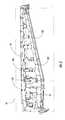
- FIG. 1is a schematic diagram of a shim constructed using a shape determined by the present invention
- FIG. 2is a perspective view of a strut torque box marked with targets that indicate shim point locations for measurement using the present invention
- FIG. 3is a schematic illustrating the creation of a plurality of points and the construction of a planar surface according to one embodiment of the present invention.
- FIG. 4Ais a schematic of a plurality of measured points projected onto a plane by a processing element in another embodiment of the present invention.
- FIG. 4Bis a schematic of the plurality of measured points in FIG. 4A transformed to one side of the plane using the processing element;
- FIG. 5is a schematic of a point to surface shim placed between a hinge of a thrust reverser and an outer mold line of a skin and having a thickness determined by another embodiment of the present invention
- FIG. 6is a flowchart of a process of the present invention for determining the shape of a shim by constructing a new surface from a group of new points;
- FIG. 7is a flowchart of a process of the present invention for determining the shape of a shim by realigning a group of measured points to a group of new points;
- FIG. 8is a flowchart of a process of the present invention for determining the shape of a shim by performing a maximum material best fit to a surface.
- a shim 98is positioned between two surfaces.
- the first surfaceis defined as the outer surface of a first body, in this case a strut torque box 102 .
- the second surfaceis defined as the inner surface of a second body, in this case a torque box skin 100 .
- the shim 98can be positioned between a wide variety of other surfaces, if so desired. Additionally, the shim may be positioned between more than two bodies and may accordingly have a more complex design in certain circumstances.
- the shim 98may be any shape or contour, and often has a rectangular or square footprint. To determine the shape of the shim, a single point or a series of points may be measured, as described below, for each shim position depending upon the desired accuracy of shim construction. These points are thereafter utilized to construct the shape of the shim.
- the shim pointscan be measured during the course of a single measurement, as opposed to conventional methods that require multiple measurements for each shim.
- Measurement of the shim positions upon one of the surfaces, such as the strut torque box 102is performed using a measuring device.
- digital photogrammetry equipmentcan be used as the measuring device, preferably from Geodetic Services, Inc. of Melbourne, Fla.
- the shim pointsare targeted by the digital photogrammetry equipment using retro-reflective targets 103 applied at each individual shim point.
- FIG. 2shows the measurement locations of the reflective targets 103 on one side of the strut torque box 102 , and shows each shim position segmented by lines.
- a single cameramay be used and typically takes up to 80 pictures of the torque box from 80 different positions.
- four cameras in different positionsare used in a real time configuration for quick and accurate measurement.
- the result of the measurementsyield three-dimensional coordinates for a plurality of points at each shim location, which are used to determine the shape and thickness of the shims needed to secure the skin to the strut torque box in this example.
- Other methodscan be used to measure the shim points such as a linkage with a stylus or radio frequency equipment, but digital photogrammetry is preferred due to the quickness of the measurement and its accuracy.
- the markersmay be placed using other materials, such as spray dots, LED's and the like, but retro-reflective markers yield an excellent contrast for easy detection by the photogrammetry equipment under controlled lighting.
- the process for determining the thickness of shimsuses a planar based analysis.
- the first embodimentis illustrated as applied to an engine strut used in the aerospace industry, it is also preferred for applications that require shims in areas that are relatively flat or planar in nature.
- a struthangs from the wing of an aircraft and includes the strut torque box 102 to which an engine is to be mounted. Each side of the strut torque box 102 comprises two planes, a forward plane 51 and an aft plane 52 .
- the number of points measured by the photogrammetry devicemay be varied as desired, but in the present embodiment 55 points (L 111 -L 165 ) are measured on the aft plane 52 and 110 points (L 1 -L 110 ) are measured on the forward plane 51 .
- the groups of measured pointsare used to determine the shape of a plurality of the shims 98 , as shown in block 202 of FIG. 6 . In the present example, four points are used, one for each corner, to determine the shape and thickness of each shim.
- the number of measured pointsmay be varied based on the complexity of the surface and the level of precision required. Additional points may be used for larger or more complicated shims and less points for less complicated shims.
- the pointsare referenced to hard tooling landmarks, such as the hinges of the strut torque box (not shown), that are detected by the photogrammetry device while measuring the measured points.
- the hard tooling landmarksallow the measured points (L) to be transformed into a coordinate system having an engineering surface 104 that is a model, typically obtained from a CAD or similar system, of either the forward or aft planes 51 , 52 , as shown in block 203 of FIG. 6 . This type of transformation is common to the art and is therefore not described herein in any further detail.
- three points L 1 , L 28 and L 30are selected from the cloud of measured points (L) to form a surface 106 . As described above, however, additional points could be selected if so desired. Together, the surface 106 and the measured points (L) define the shape of the shim 98 , as described below.
- the three pointspreferably have a good distribution across the engineering surface 104 . For instance, the most outboard point is selected near each opposing edge and a third in the middle of the engineering surface 104 .
- each measured pointis not itself used to construct the plane 106 , but rather a new point (VL) on the same vector (described below) is constructed and that new point is used to construct the plane.
- the new point (VL)is constructed by defining a line that passes through the measured point (L) and is normal to the engineering surface 104 .
- a point (PL)is created at the intersection of the line and the engineering surface 104 .
- a vector 53is created from the point (PL) on the engineering surface and the measured point (L).
- a new point (VL)is created using a predetermined outboard displacement along the same vector 53 as the designated measured point (L) and the surface point (PL).
- the top and bottom surfaces of the shim 98are modeled by the engineering surface 104 and the plane 106 .
- the engineering surface 104represents the mating surface of the strut torque box 102 .
- the plane 106represents the mating surface of the torque box skin 100 offset by an engineering tolerance to slightly thicken the shim 98 so that it can be lodged between the strut torque box and torque box skin in an interference fit.
- the outboard displacement from each designated measurement point (L) to the respective new point (VL)is separately determined for each designated measurement point based upon the distance between the engineering surface 104 and the outboard-most point in a region around the respective measurement point, (e.g., L 1 , L 28 , and L 30 ), as shown in block 204 of FIG. 6 .
- the size and location of the region around each designated measurement pointcan be defined by an algorithm or manually by a person skilled in the art. If three points are used to create the plane, then three equal regions are used.
- the outboard-most points in each local regioncan be selected to also be the designated measuring points (L), such that the displacement of the new points (VL) from the designated measuring points is the same as the displacement of the designated measuring points from the engineering surface 104 minus the engineering tolerance.
- a first new point VL 1is constructed a distance D 1 away from the measured point L 1 along the vector 53 defined by the points PL 1 and L 1 .
- D 1is equal to the displacement of the most-outboard point in the region around L 1 from the engineering surface 104 .
- New points VL 28 and VL 30are created in a similar manner from displacements D 28 and D 30 , respectively.
- the planar surface 106is then constructed and fit to the three new points VL 1 , VL 28 and VL 30 , as shown in block 206 of FIG. 6 .
- the three new pointsare repositioned in increments, changing the orientation of the planar surface 106 , until all of the measured points (L) protrude less than a predetermined engineering tolerance into the surface 106 in the direction of the arrow 107 in FIG. 3 .
- the incrementsare determined by observing how much the plurality of points project into the plane. This is achieved by measuring the point-to-plane distance for all points, e.g., L 1 -L 110 . Repositioning the three new points adjusts the planar surface 106 to thicken the shim 98 and provide an interference fit of a predetermined amount.
- the engineering requirements for the strut torque box 102 and torque box skin 100allow for a 0.005 inch interference fit.
- any measured pointL 1 -L 110 or L 111 -L 165
- the locations of the new points VL 1 , VL 28 , and VL 30are moved by small variations and plane 106 is redefined until all measured points (L 1 -L 110 or L 111 -L 165 ) protrude no more than 0.005 inches into the plane 106 created by the new points, as shown in block 207 of FIG. 6 .
- the distance between all of the measured points (L 1 -L 110 or L 111 -L 165 ), that are associated with the shim location and the plane 106is measured.
- the distance from the plane 106 to the measured pointsis the shape or thickness of the shim 98 at that particular location.
- a report of the results generatedis given to a mechanic or shim milling machine for manufacture of the shim 98 .
- the processing elementcan include, without limitation, a single microprocessor, such as in a personal computer, multiple processors, such as in a mainframe, a UNIX workstation or some collection of software, firmware, hardware, or some combination thereof. Part or all of the data manipulation may be performed by a processing element included with the measurement equipment (e.g., the digital photogrammetry equipment) or in cooperation with other processors.
- a processing elementincluded with the measurement equipment (e.g., the digital photogrammetry equipment) or in cooperation with other processors.
- a computer program productserves as the processing element.
- the computer program productincludes a computer-readable storage medium having computer-readable program code means, such as a series of computer instructions embodied in the computer-readable storage medium for determining the shape of a shim that can be inserted between a first body and a second body.
- FIGS. 6, 7 , and 8are flowchart illustrations of methods, systems and program products according to the invention. It will be understood that each block or step of the flow chart, and combinations of blocks or steps in the flowchart, can be implemented by computer program instructions. These computer program instructions may be loaded onto a computer or other programmable apparatus to produce a machine, such that the instructions which execute on the computer or other programmable apparatus create means for implementing the functions specified in the flowchart flow block(s) or step(s).
- These computer program instructionsmay also be stored in a computer-readable memory that can direct a computer or other programmable apparatus to function in a particular manner, such that the instructions stored in the computer-readable memory produce an article of manufacture including instruction means which implement the function specified in the flowchart flow block(s) or step(s).
- the computer program instructionsmay also be loaded onto a computer or other programmable apparatus to cause of series of operational steps to be performed on the computer or other programmable apparatus to produce a computer implemented process such that the instructions which execute on the computer or other programmable apparatus provide steps for implementing the functions specified in the flowchart flow block(s) or step(s).
- blocks or steps of the flowchartsupport combinations of means for performing the specified functions, combinations of steps for performing the specified functions and program instruction means for performing the specified functions. It will also be understood that each block or step of flowchart, and combinations of blocks or steps in the flowchart, can be implemented by special purpose hardware-based computer systems which perform the specified functions or steps, or combinations of special purpose hardware and computer instructions.
- Another embodiment of the present inventionuses a surface analysis method to determine shim thickness.
- Surface analysisprovides more flexibility than the aforementioned planar analysis because it can be used on non-planar surfaces. There is no requirement that the plane constructed on each side of the strut torque box 102 must intersect the measured points (L 1 -L 110 or L 111 -L 165 ) within the allowable engineering interference.
- shim pointsare typically marked using retro-reflective markers which are measured in three-dimensions by photogrammetry equipment, as shown in FIG. 2 and block 212 of FIG. 7 .
- the results of the measurementsare projected to an inner mold line engineering surface that serves as an outboard mating surface 120 , not on the strut torque box 102 as in the first embodiment, but on the torque box skin 100 , as shown in block 213 of FIG. 7 .
- the outboard mating surfaceis a design surface, typically provided by a CAD or similar system, having a coordinate system into which the measured points (L) are imported.
- three measured pointsare designated as measuring points (e.g., L 1 , L 28 , L 30 ).
- the outboard-most measured pointis selected and the distance between the point and the outboard mating surface 120 is noted, as shown in block 214 of FIG. 7 . If there is a point L 2 immediately adjacent to L 1 for instance that is 0.050 inches outboard of the skin surface, and the point L 2 is the outboard-most point in the region around L 1 , then the distance from L 2 to the skin surface is noted.
- FIG. 4Ashows how each of the measured points are projected to outboard mating surface 120 , as indicated by the open circles on surface 120 .
- a new point (VL)is created along the vector 53 defined to extend in the inboard direction normal to the mating surface 120 and through a respective point (L), as shown in block 215 of FIG. 7 .
- the new point (VL)is spaced from the designated measuring point in an inboard direction by the noted distance of the locally outboard-most point from the outboard mating surface 120 , any engineering interference allowance (0.005 inches in this case).
- FIG. 4Bshows the results of the second set of point to surface 120 measurements as indicated by the lines.
- the distance of each measured point (L) from the outboard mating surface 120is the thickness of the shim 98 at that location.
- a report of the results generatedis given to a mechanic or shim milling machine for manufacture of the shim 98 .
- this embodimentis different from the first embodiment in that the group of measured points are being moved with respect to the design surface. Basically, the new points (VL) are created and the measured points (L) are moved until the designated measured points overlap the new points. Moving the measured points changes their orientation with respect to the design surface. The relative positions and orientations of the measured points with respect to each other, however, are not changed. In the first embodiment, the surface is moved with respect to the measured points, which are fixed.
- the inner mold line of the outboard mating surfaceis again used to determine the shim thickness, as shown in FIG. 8 .
- all measured pointsare used to perform a “best-fit” to the outboard mating surface 120 of the torque box skin 100 , as shown in blocks 222 and 223 of FIG. 8 .
- the “best-fit”is not a normal least-squares best fit, but instead a “maximum-material condition best-fit,” where all the measured points are best-fit to one side of the mating surface 120 .
- the mating surfaceis offset by the allowable engineering interference (0.005 inches in this case) and the entire measured data set (L 1 -L 110 or L 111 -L 165 ) is used to determine the minimum shim thickness, as shown in block 224 of FIG. 8 .
- Each measured point to surface thicknessis the shim thickness at each measured location.
- the use of a maximum-material condition best-fitis not limited to planar shims.
- the measured pointsare not relocated.
- the shim thicknessis determined by calculating the point to surface deviation. The method is particularly useful when a point-to-surface shim 111 is needed in an area where the surface location is critical.
- a thrust reverser (TR) hinge 112is installed on an outer mold line of the strut skin. The location of the hinge 112 is critical because the hole 114 of the hinge 112 is used to locate and install the thrust reverser.
- the TR hinge 112is tool-located using a pin that goes through the tool-locating detail and through the TR hinge hole 114 . The assumption made for this analysis is that the TR hinge 112 detail part is manufactured to exact engineering specifications.
- the measurement equipmentis used to measure points P 1 , P 2 on the skin or outer mold line surface 110 at the locations where the TR hinges 112 are to be installed.
- the thickness of the shimis determined by calculating the distance between points P 1 , P 2 and the TR hinge 112 mating surface.
- a report of the point-to-surface thickness informationis given to a mechanic or shim milling machine for manufacture of the shim 111 .
- the finished shimcan be installed between the TR hinge 112 mating surface and the outer mold line surface 110 .
- the present inventionhas several advantages.
- One advantageis that the time consuming process of measuring multiple shim points individually and by hand in tight spaces with a feeler gauge has been eliminated.
- the present inventionallows all of the points to be measured simultaneously for multiple shims, saving upwards of 50% to 75% on measurement, manufacture and installation time.
- Another advantageis that the mating parts do not have to be pre-assembled for the measurements to be taken.
- Weight reductionis of considerable importance in aerospace applications. The weight of each shim is reduced because the algorithm minimizes the shim thickness, resulting in a 5 to 10 pound weight reduction for the entire strut.
Landscapes
- Engineering & Computer Science (AREA)
- Manufacturing & Machinery (AREA)
- Transportation (AREA)
- Aviation & Aerospace Engineering (AREA)
- Length Measuring Devices By Optical Means (AREA)
- Length Measuring Devices With Unspecified Measuring Means (AREA)
Abstract
Description
Claims (42)
Priority Applications (3)
| Application Number | Priority Date | Filing Date | Title |
|---|---|---|---|
| US09/800,026US6618505B2 (en) | 2000-03-09 | 2001-03-06 | Method, apparatus and computer program product for determining shim shape |
| AU2001252898AAU2001252898A1 (en) | 2000-03-09 | 2001-03-07 | Method, apparatus and computer program product for determining shim shape |
| PCT/US2001/007470WO2001066414A1 (en) | 2000-03-09 | 2001-03-07 | Method, apparatus and computer program product for determining shim shape |
Applications Claiming Priority (2)
| Application Number | Priority Date | Filing Date | Title |
|---|---|---|---|
| US18811300P | 2000-03-09 | 2000-03-09 | |
| US09/800,026US6618505B2 (en) | 2000-03-09 | 2001-03-06 | Method, apparatus and computer program product for determining shim shape |
Publications (2)
| Publication Number | Publication Date |
|---|---|
| US20010046323A1 US20010046323A1 (en) | 2001-11-29 |
| US6618505B2true US6618505B2 (en) | 2003-09-09 |
Family
ID=26883739
Family Applications (1)
| Application Number | Title | Priority Date | Filing Date |
|---|---|---|---|
| US09/800,026Expired - LifetimeUS6618505B2 (en) | 2000-03-09 | 2001-03-06 | Method, apparatus and computer program product for determining shim shape |
Country Status (3)
| Country | Link |
|---|---|
| US (1) | US6618505B2 (en) |
| AU (1) | AU2001252898A1 (en) |
| WO (1) | WO2001066414A1 (en) |
Cited By (21)
| Publication number | Priority date | Publication date | Assignee | Title |
|---|---|---|---|---|
| US6868609B1 (en)* | 2002-01-15 | 2005-03-22 | Torque-Traction Technologies, Inc. | Method and apparatus for preloading pinion bearings |
| US20070263229A1 (en)* | 2006-05-10 | 2007-11-15 | Marsh Bobby J | Laser and photogrammetry merged process |
| US20080205763A1 (en)* | 2007-02-28 | 2008-08-28 | The Boeing Company | Method for fitting part assemblies |
| US20080223985A1 (en)* | 2007-03-14 | 2008-09-18 | The Boeing Company | Splicing Fuselage Sections without Shims |
| US20080256788A1 (en)* | 2005-09-22 | 2008-10-23 | Airbus Uk Limited | Assembly of Aircraft Components |
| US20090100791A1 (en)* | 2007-10-23 | 2009-04-23 | Airbus Uk Limited | Shim for arrangement against a structural component and a method of making a shim |
| US20120316666A1 (en)* | 2011-06-08 | 2012-12-13 | The Boeing Company | Digitally designed shims for joining parts of an assembly |
| US9068809B1 (en) | 2013-06-06 | 2015-06-30 | The Boeing Company | Quasi-virtual locate/drill/shim process |
| US9213786B2 (en) | 2013-02-20 | 2015-12-15 | The Boeing Company | Manufacturing systems and methods |
| US9573198B1 (en) | 2013-06-06 | 2017-02-21 | The Boeing Company | Double eccentric positioning apparatus |
| EP3187946A1 (en)* | 2015-12-30 | 2017-07-05 | Airbus Group SAS | Device and method for correcting geometrical differences of the surfaces of parts to be assembled at the interface of the assembly |
| US10139808B2 (en) | 2016-09-07 | 2018-11-27 | The Boeing Company | Predictive shimming of joints |
| US10275565B2 (en) | 2015-11-06 | 2019-04-30 | The Boeing Company | Advanced automated process for the wing-to-body join of an aircraft with predictive surface scanning |
| US10450053B2 (en) | 2016-05-11 | 2019-10-22 | The Boeing Company | Methods using predictive shimming to optimize part-to-part alignment |
| US10521551B2 (en) | 2015-11-16 | 2019-12-31 | The Boeing Company | Methods for shimming flexible bodies |
| US10712730B2 (en) | 2018-10-04 | 2020-07-14 | The Boeing Company | Methods of synchronizing manufacturing of a shimless assembly |
| US10843821B2 (en) | 2019-01-03 | 2020-11-24 | The Boeing Company | Predictive preparation of material for joint assembly |
| US11181887B2 (en) | 2018-12-14 | 2021-11-23 | The Boeing Company | Predictive surface adjustment for joint assembly |
| US11396071B2 (en)* | 2019-03-13 | 2022-07-26 | The Boeing Company | Shim manufacturing methods and devices |
| US11801946B2 (en) | 2019-04-25 | 2023-10-31 | The Boeing Company | System for sensing miniature gaps by inductive coupling |
| US12391409B2 (en) | 2023-07-18 | 2025-08-19 | Blue Origin Manufacturing, LLC | Rocket thrust structure assembly, and associated systems and methods |
Families Citing this family (9)
| Publication number | Priority date | Publication date | Assignee | Title |
|---|---|---|---|---|
| US7235280B2 (en) | 2003-11-12 | 2007-06-26 | Srs Technologies, Inc. | Non-intrusive photogrammetric targets |
| ITTO20070697A1 (en)* | 2007-10-03 | 2009-04-04 | Alenia Aeronautica Spa | PROCEDURE FOR THE ASSEMBLY OF FULL STRUCTURES |
| US9586367B2 (en)* | 2008-11-04 | 2017-03-07 | Lockheed Martin Corporation | Composite laminate thickness compensation |
| ES2386442B1 (en)* | 2009-11-27 | 2013-07-09 | Airbus Operations S.L. | AIRCRAFT TIMER HEAD. |
| US9186849B2 (en)* | 2009-12-10 | 2015-11-17 | Michael Spellman | Composite part manufacturing compensation system and method |
| CN101791761A (en)* | 2010-04-07 | 2010-08-04 | 中国航空工业集团公司北京航空制造工程研究所 | Method for compensating for matching surface gap of skeleton and skin of aircraft structure |
| US8655480B1 (en) | 2010-11-11 | 2014-02-18 | The Boeing Company | Automated filler production method |
| DE102014107855A1 (en)* | 2014-06-04 | 2015-12-17 | Airbus Operations Gmbh | Method and device for aligning segments |
| CN112824100A (en)* | 2019-11-21 | 2021-05-21 | 成都飞机工业(集团)有限责任公司 | Composite gasket adaptive to overall dimension and preparation method thereof |
Citations (27)
| Publication number | Priority date | Publication date | Assignee | Title |
|---|---|---|---|---|
| US4649752A (en)* | 1986-01-06 | 1987-03-17 | The Boeing Company | Shim gap probe |
| US4663858A (en)* | 1986-02-07 | 1987-05-12 | The Boeing Company | Apparatus for measuring dimensions of a slit |
| US4744153A (en)* | 1986-09-22 | 1988-05-17 | Outboard Marine Corporation | Method and apparatus for determining the thickness of shim required for properly loading and positioning the bearing assembly of a marine propulsion device drive shaft |
| US4814691A (en) | 1985-08-09 | 1989-03-21 | Washington Research Foundation | Fringe field capacitive sensor for measuring profile of a surface |
| US4814703A (en) | 1987-08-04 | 1989-03-21 | The Boeing Company | Method and apparatus for gap measurement between a graphite/epoxy structure and a metallic model |
| EP0308539A1 (en) | 1987-09-25 | 1989-03-29 | Waldrich Siegen Werkzeugmaschinenbau GmbH | Method and a positioning system or apparatus for orienting an actual surface, for example of a form, on an internal coordinate system of a machine moving in relation to it, in particular a multi-axis band laying machine |
| US4841224A (en) | 1987-11-10 | 1989-06-20 | Washington Technology Center | Gap width probe and method |
| US4848137A (en) | 1988-03-23 | 1989-07-18 | The Boeing Company | Automated shim manufacturing system |
| US4935700A (en)* | 1985-08-09 | 1990-06-19 | Washington Research Foundation | Fringe field capacitive sensor for measuring the size of an opening |
| US4993165A (en)* | 1989-07-31 | 1991-02-19 | Outboard Marine Corporation | Method and apparatus for determining necessary shim thickness for a marine propulsion device pinion and bearing carrier assembly |
| US5033014A (en)* | 1987-04-14 | 1991-07-16 | Northrop Corporation | Integrated manufacturing system |
| US5106290A (en) | 1987-04-14 | 1992-04-21 | Northrop Corporation | Assembly data model tool system |
| US5129010A (en)* | 1989-12-15 | 1992-07-07 | Kabushiki Kaisha Toyoto Chuo Kenkyusho | System for measuring shapes and dimensions of gaps and flushnesses on three dimensional surfaces of objects |
| US5189377A (en)* | 1990-09-04 | 1993-02-23 | Extrude Hone Corporation | Method and apparatus for co-ordinate measuring using a capacitance probe |
| US5251156A (en) | 1990-08-25 | 1993-10-05 | Carl-Zeiss-Stiftung, Heidenheim/Brenz | Method and apparatus for non-contact measurement of object surfaces |
| US5312211A (en) | 1990-05-04 | 1994-05-17 | Aerospatiale Societe Nationale Industrielle | Method and system for embodying a plane reference surface defined by a specific equation on an assembling frame of a structure from a rough surface |
| US5385050A (en) | 1992-04-07 | 1995-01-31 | Northrop Grumman Corporation | Gap measurement for shim manufacture |
| US5506682A (en)* | 1982-02-16 | 1996-04-09 | Sensor Adaptive Machines Inc. | Robot vision using targets |
| US5510625A (en)* | 1979-04-30 | 1996-04-23 | Sensor Adaptive Machines Inc. | Method and apparatus for electro optically determining the dimension, location and attitude of objects |
| US5546008A (en)* | 1994-08-11 | 1996-08-13 | General Electric Co. | Inflatable capacitance measuring device |
| US5642293A (en)* | 1996-06-03 | 1997-06-24 | Camsys, Inc. | Method and apparatus for determining surface profile and/or surface strain |
| US5696687A (en) | 1995-11-01 | 1997-12-09 | Fanuc Robotics North America, Inc. | Apparatus and method for graphically interfacing operator with programmable fixture devices |
| US5796856A (en)* | 1994-08-24 | 1998-08-18 | Eastman Kodak Company | Gap measuring apparatus and method |
| US5805289A (en)* | 1997-07-07 | 1998-09-08 | General Electric Company | Portable measurement system using image and point measurement devices |
| US5963660A (en) | 1996-09-26 | 1999-10-05 | The Boeing Company | Method and apparatus for detecting and measuring laps and gaps in composite materials |
| EP0957335A2 (en) | 1998-05-11 | 1999-11-17 | Northrop Grumman Corporation (a Delaware Corporation) | System and method for assembling an aircraft |
| US5999265A (en) | 1996-12-02 | 1999-12-07 | Espace Industrie Controles S.A. | System for measuring gap and mismatch between opposing parts |
- 2001
- 2001-03-06USUS09/800,026patent/US6618505B2/ennot_activeExpired - Lifetime
- 2001-03-07AUAU2001252898Apatent/AU2001252898A1/ennot_activeAbandoned
- 2001-03-07WOPCT/US2001/007470patent/WO2001066414A1/enactiveApplication Filing
Patent Citations (27)
| Publication number | Priority date | Publication date | Assignee | Title |
|---|---|---|---|---|
| US5510625A (en)* | 1979-04-30 | 1996-04-23 | Sensor Adaptive Machines Inc. | Method and apparatus for electro optically determining the dimension, location and attitude of objects |
| US5506682A (en)* | 1982-02-16 | 1996-04-09 | Sensor Adaptive Machines Inc. | Robot vision using targets |
| US4814691A (en) | 1985-08-09 | 1989-03-21 | Washington Research Foundation | Fringe field capacitive sensor for measuring profile of a surface |
| US4935700A (en)* | 1985-08-09 | 1990-06-19 | Washington Research Foundation | Fringe field capacitive sensor for measuring the size of an opening |
| US4649752A (en)* | 1986-01-06 | 1987-03-17 | The Boeing Company | Shim gap probe |
| US4663858A (en)* | 1986-02-07 | 1987-05-12 | The Boeing Company | Apparatus for measuring dimensions of a slit |
| US4744153A (en)* | 1986-09-22 | 1988-05-17 | Outboard Marine Corporation | Method and apparatus for determining the thickness of shim required for properly loading and positioning the bearing assembly of a marine propulsion device drive shaft |
| US5106290A (en) | 1987-04-14 | 1992-04-21 | Northrop Corporation | Assembly data model tool system |
| US5033014A (en)* | 1987-04-14 | 1991-07-16 | Northrop Corporation | Integrated manufacturing system |
| US4814703A (en) | 1987-08-04 | 1989-03-21 | The Boeing Company | Method and apparatus for gap measurement between a graphite/epoxy structure and a metallic model |
| EP0308539A1 (en) | 1987-09-25 | 1989-03-29 | Waldrich Siegen Werkzeugmaschinenbau GmbH | Method and a positioning system or apparatus for orienting an actual surface, for example of a form, on an internal coordinate system of a machine moving in relation to it, in particular a multi-axis band laying machine |
| US4841224A (en) | 1987-11-10 | 1989-06-20 | Washington Technology Center | Gap width probe and method |
| US4848137A (en) | 1988-03-23 | 1989-07-18 | The Boeing Company | Automated shim manufacturing system |
| US4993165A (en)* | 1989-07-31 | 1991-02-19 | Outboard Marine Corporation | Method and apparatus for determining necessary shim thickness for a marine propulsion device pinion and bearing carrier assembly |
| US5129010A (en)* | 1989-12-15 | 1992-07-07 | Kabushiki Kaisha Toyoto Chuo Kenkyusho | System for measuring shapes and dimensions of gaps and flushnesses on three dimensional surfaces of objects |
| US5312211A (en) | 1990-05-04 | 1994-05-17 | Aerospatiale Societe Nationale Industrielle | Method and system for embodying a plane reference surface defined by a specific equation on an assembling frame of a structure from a rough surface |
| US5251156A (en) | 1990-08-25 | 1993-10-05 | Carl-Zeiss-Stiftung, Heidenheim/Brenz | Method and apparatus for non-contact measurement of object surfaces |
| US5189377A (en)* | 1990-09-04 | 1993-02-23 | Extrude Hone Corporation | Method and apparatus for co-ordinate measuring using a capacitance probe |
| US5385050A (en) | 1992-04-07 | 1995-01-31 | Northrop Grumman Corporation | Gap measurement for shim manufacture |
| US5546008A (en)* | 1994-08-11 | 1996-08-13 | General Electric Co. | Inflatable capacitance measuring device |
| US5796856A (en)* | 1994-08-24 | 1998-08-18 | Eastman Kodak Company | Gap measuring apparatus and method |
| US5696687A (en) | 1995-11-01 | 1997-12-09 | Fanuc Robotics North America, Inc. | Apparatus and method for graphically interfacing operator with programmable fixture devices |
| US5642293A (en)* | 1996-06-03 | 1997-06-24 | Camsys, Inc. | Method and apparatus for determining surface profile and/or surface strain |
| US5963660A (en) | 1996-09-26 | 1999-10-05 | The Boeing Company | Method and apparatus for detecting and measuring laps and gaps in composite materials |
| US5999265A (en) | 1996-12-02 | 1999-12-07 | Espace Industrie Controles S.A. | System for measuring gap and mismatch between opposing parts |
| US5805289A (en)* | 1997-07-07 | 1998-09-08 | General Electric Company | Portable measurement system using image and point measurement devices |
| EP0957335A2 (en) | 1998-05-11 | 1999-11-17 | Northrop Grumman Corporation (a Delaware Corporation) | System and method for assembling an aircraft |
Non-Patent Citations (1)
| Title |
|---|
| Copy of PCT International Search Report for PCT/US01/07470, completed Jul. 19, 2001. |
Cited By (40)
| Publication number | Priority date | Publication date | Assignee | Title |
|---|---|---|---|---|
| US6951146B1 (en) | 2002-01-15 | 2005-10-04 | Torque-Traction Technologies, Inc. | Method and apparatus for preloading pinion bearings |
| US6868609B1 (en)* | 2002-01-15 | 2005-03-22 | Torque-Traction Technologies, Inc. | Method and apparatus for preloading pinion bearings |
| US8479394B2 (en)* | 2005-09-22 | 2013-07-09 | Airbus Operations Limited | Assembly of aircraft components |
| US20080256788A1 (en)* | 2005-09-22 | 2008-10-23 | Airbus Uk Limited | Assembly of Aircraft Components |
| US20070263229A1 (en)* | 2006-05-10 | 2007-11-15 | Marsh Bobby J | Laser and photogrammetry merged process |
| US7454265B2 (en)* | 2006-05-10 | 2008-11-18 | The Boeing Company | Laser and Photogrammetry merged process |
| EP2368799A1 (en) | 2007-02-28 | 2011-09-28 | The Boeing Company | Method for fitting part assemblies |
| US20080205763A1 (en)* | 2007-02-28 | 2008-08-28 | The Boeing Company | Method for fitting part assemblies |
| WO2008106249A2 (en) | 2007-02-28 | 2008-09-04 | The Boeing Company | Method for fitting part assemblies |
| US7756321B2 (en) | 2007-02-28 | 2010-07-13 | The Boeing Company | Method for fitting part assemblies |
| US7957825B2 (en)* | 2007-03-14 | 2011-06-07 | The Boeing Company | Splicing fuselage sections without shims |
| US20100280648A1 (en)* | 2007-03-14 | 2010-11-04 | The Boeing Company | Splicing Fuselage Sections Without Shims |
| US7787979B2 (en)* | 2007-03-14 | 2010-08-31 | The Boeing Company | Splicing fuselage sections without shims |
| US20080223985A1 (en)* | 2007-03-14 | 2008-09-18 | The Boeing Company | Splicing Fuselage Sections without Shims |
| US8621819B2 (en)* | 2007-10-23 | 2014-01-07 | Airbus Operations Limited | Shim for arrangement against a structural component and a method of making a shim |
| US20090100791A1 (en)* | 2007-10-23 | 2009-04-23 | Airbus Uk Limited | Shim for arrangement against a structural component and a method of making a shim |
| US9429935B2 (en) | 2011-06-08 | 2016-08-30 | The Boeing Company | Methods of fabricating shims for joining parts |
| US8756792B2 (en)* | 2011-06-08 | 2014-06-24 | The Boeing Company | Digitally designed shims for joining parts of an assembly |
| US20120316666A1 (en)* | 2011-06-08 | 2012-12-13 | The Boeing Company | Digitally designed shims for joining parts of an assembly |
| US9213786B2 (en) | 2013-02-20 | 2015-12-15 | The Boeing Company | Manufacturing systems and methods |
| US9068809B1 (en) | 2013-06-06 | 2015-06-30 | The Boeing Company | Quasi-virtual locate/drill/shim process |
| US9435633B2 (en) | 2013-06-06 | 2016-09-06 | The Boeing Company | Quasi-virtual locate/drill/shim process |
| US9573198B1 (en) | 2013-06-06 | 2017-02-21 | The Boeing Company | Double eccentric positioning apparatus |
| US10473201B2 (en) | 2013-06-06 | 2019-11-12 | The Boeing Company | Double eccentric positioning apparatus |
| US10275565B2 (en) | 2015-11-06 | 2019-04-30 | The Boeing Company | Advanced automated process for the wing-to-body join of an aircraft with predictive surface scanning |
| US11188688B2 (en) | 2015-11-06 | 2021-11-30 | The Boeing Company | Advanced automated process for the wing-to-body join of an aircraft with predictive surface scanning |
| US10521551B2 (en) | 2015-11-16 | 2019-12-31 | The Boeing Company | Methods for shimming flexible bodies |
| US10562246B2 (en) | 2015-12-30 | 2020-02-18 | Airbus | Device and method for correction of geometrical differences of the surfaces of parts to be assembled at the assembly interface |
| FR3046369A1 (en)* | 2015-12-30 | 2017-07-07 | Airbus Group Sas | DEVICE AND METHOD FOR CORRECTING GEOMETRIC DIFFERENCES OF THE SURFACES OF PARTS TO BE ASSEMBLED AT THE INTERFACE OF THE ASSEMBLY |
| EP3187946A1 (en)* | 2015-12-30 | 2017-07-05 | Airbus Group SAS | Device and method for correcting geometrical differences of the surfaces of parts to be assembled at the interface of the assembly |
| US10450053B2 (en) | 2016-05-11 | 2019-10-22 | The Boeing Company | Methods using predictive shimming to optimize part-to-part alignment |
| US10139808B2 (en) | 2016-09-07 | 2018-11-27 | The Boeing Company | Predictive shimming of joints |
| US10712730B2 (en) | 2018-10-04 | 2020-07-14 | The Boeing Company | Methods of synchronizing manufacturing of a shimless assembly |
| US11294357B2 (en) | 2018-10-04 | 2022-04-05 | The Boeing Company | Methods of synchronizing manufacturing of a shimless assembly |
| US11415968B2 (en) | 2018-10-04 | 2022-08-16 | The Boeing Company | Methods of synchronizing manufacturing of a shimless assembly |
| US11181887B2 (en) | 2018-12-14 | 2021-11-23 | The Boeing Company | Predictive surface adjustment for joint assembly |
| US10843821B2 (en) | 2019-01-03 | 2020-11-24 | The Boeing Company | Predictive preparation of material for joint assembly |
| US11396071B2 (en)* | 2019-03-13 | 2022-07-26 | The Boeing Company | Shim manufacturing methods and devices |
| US11801946B2 (en) | 2019-04-25 | 2023-10-31 | The Boeing Company | System for sensing miniature gaps by inductive coupling |
| US12391409B2 (en) | 2023-07-18 | 2025-08-19 | Blue Origin Manufacturing, LLC | Rocket thrust structure assembly, and associated systems and methods |
Also Published As
| Publication number | Publication date |
|---|---|
| US20010046323A1 (en) | 2001-11-29 |
| WO2001066414A1 (en) | 2001-09-13 |
| AU2001252898A1 (en) | 2001-09-17 |
Similar Documents
| Publication | Publication Date | Title |
|---|---|---|
| US6618505B2 (en) | Method, apparatus and computer program product for determining shim shape | |
| CN109596059B (en) | A method for measuring the gap and step difference of aircraft skin based on parallel line structured light | |
| EP3244329B1 (en) | Methods using predictive shimming to optimize part-to-part alignment | |
| US8005563B2 (en) | System for assembling aircraft | |
| US9429935B2 (en) | Methods of fabricating shims for joining parts | |
| US7372558B2 (en) | Method and system for visualizing surface errors | |
| US7756321B2 (en) | Method for fitting part assemblies | |
| US10393504B2 (en) | Optical coordinate measurement system | |
| US8326587B2 (en) | System, method, and computer program product for predicting cruise orientation of an as-built airplane | |
| US20030167147A1 (en) | Assembly method | |
| US11421980B2 (en) | Method for determining a position and orientation of an object using a profilometer | |
| Jiang et al. | Template matching of freeform surfaces based on orthogonal distance fitting for precision metrology | |
| US20090151143A1 (en) | System, method, and computer program product for computing orientation alignment transfer tool locations to transfer predicted cruise orientation alignment of an as-built airplane | |
| EP3736218B1 (en) | Process of joining a wing to an aircraft fuselage | |
| Venkatakrishnan | Comparative study of different pressure-sensitive-paint image registration techniques | |
| Confalone et al. | Metrology Glossary | |
| CN114492016B (en) | A method for precise matching and adjustment of vehicle doors and vehicle body sides based on scanning measurement | |
| US20250139784A1 (en) | Method and System for Ply Boundary Detection | |
| Allen et al. | Computer‐Aided Marine Propeller Inspection Data Analysis | |
| Li et al. | A further study on adaptive wall strategy for half-model testing | |
| Palmateer | Optical Layup Template | |
| Allen et al. | Computer aided design methods for propeller fillet gages | |
| Seidenman | Theodolites improve manufacturing |
Legal Events
| Date | Code | Title | Description |
|---|---|---|---|
| AS | Assignment | Owner name:BOEING COMPANY, THE, WASHINGTON Free format text:ASSIGNMENT OF ASSIGNORS INTEREST;ASSIGNORS:CORK, GLEN P.;LANE, RONALD G.;REEL/FRAME:011884/0210 Effective date:20010306 | |
| STCF | Information on status: patent grant | Free format text:PATENTED CASE | |
| CC | Certificate of correction | ||
| AS | Assignment | Owner name:MID-WESTERN AIRCRAFT SYSTEMS, INC., KANSAS Free format text:ASSIGNMENT OF ASSIGNORS INTEREST;ASSIGNOR:THE BOEING COMPANY;REEL/FRAME:016164/0441 Effective date:20050616 | |
| AS | Assignment | Owner name:CITICORP NORTH AMERICA, INC., AS FIRST LIEN COLLAT Free format text:SECURITY AGREEMENT;ASSIGNOR:MID-WESTERN AIRCRAFT SYSTEMS, INC.;REEL/FRAME:016309/0090 Effective date:20050616 | |
| AS | Assignment | Owner name:SPIRIT AEROSYSTEMS, INC., KANSAS Free format text:CHANGE OF NAME;ASSIGNOR:MID-WESTERN AIRCRAFT SYSTEMS, INC.;REEL/FRAME:016712/0446 Effective date:20050719 | |
| AS | Assignment | Owner name:SPIRIT AEROSYSTEMS, INC. (F/K/A MID-WESTERN AIRCRA Free format text:RELEASE BY SECURED PARTY;ASSIGNOR:THE BOEING COMPANY;REEL/FRAME:018552/0195 Effective date:20061120 | |
| FPAY | Fee payment | Year of fee payment:4 | |
| AS | Assignment | Owner name:BANK OF AMERICA, N.A., AS COLLATERAL AGENT, CALIFO Free format text:INTELLECTUAL PROPERTY SECURITY INTEREST ASSIGNMENT AGREEMENT;ASSIGNOR:CITICORP NORTH AMERICA, INC., N.A., AS FIRST LIEN COLLATERAL AGENT;REEL/FRAME:022960/0665 Effective date:20090706 | |
| AS | Assignment | Owner name:BANK OF AMERICA, N.A., IN ITS CAPACITY AS COLLATER Free format text:AMENDMENT NO. 1 TO PATENT SECURITY AGREEMENT;ASSIGNOR:SPIRIT AEROSYSTEMS, INC. (F/K/A MID-WESTERN AIRCRAFT SYSTEMS, INC.);REEL/FRAME:023254/0919 Effective date:20090908 | |
| FPAY | Fee payment | Year of fee payment:8 | |
| AS | Assignment | Owner name:SPIRIT AEROSYSTEMS, INC. (FKA MID-WESTERN AIRCRAFT Free format text:TERMINATION AND RELEASE OF SECURITY INTEREST IN PATENTS;ASSIGNOR:BANK OF AMERICA, N.A., AS COLLATERAL AGENT (INCLUDING AS SUCCESSOR COLLATERAL AGENT TO CITICORP NORTH AMERICA, INC.);REEL/FRAME:028072/0314 Effective date:20120418 Owner name:BANK OF AMERICA, N.A., AS COLLATERAL AGENT, CALIFO Free format text:NOTICE OF GRANT OF SECURITY INTEREST IN PATENTS;ASSIGNOR:SPIRIT AEROSYSTEMS, INC.;REEL/FRAME:028072/0647 Effective date:20120418 | |
| FPAY | Fee payment | Year of fee payment:12 | |
| AS | Assignment | Owner name:SPIRIT AEROSYSTEMS, INC., KANSAS Free format text:TERMINATION AND RELEASE OF SECURITY INTEREST IN PATENTS;ASSIGNOR:BANK OF AMERICA, N.A., AS COLLATERAL AGENT;REEL/FRAME:038592/0181 Effective date:20160427 | |
| FEPP | Fee payment procedure | Free format text:PAYOR NUMBER ASSIGNED (ORIGINAL EVENT CODE: ASPN); ENTITY STATUS OF PATENT OWNER: LARGE ENTITY | |
| AS | Assignment | Owner name:BANK OF AMERICA, N.A., AS COLLATERAL AGENT, NORTH CAROLINA Free format text:NOTICE OF GRANT OF SECURITY INTEREST IN PATENTS;ASSIGNOR:SPIRIT AEROSYSTEMS, INC.;REEL/FRAME:052004/0929 Effective date:20200224 | |
| AS | Assignment | Owner name:THE BANK OF NEW YORK MELLON TRUST COMPANY, N.A., ILLINOIS Free format text:SECURITY INTEREST;ASSIGNOR:SPIRIT AEROSYSTEMS, INC.;REEL/FRAME:052433/0843 Effective date:20200417 | |
| AS | Assignment | Owner name:BANK OF AMERICA, N.A., NORTH CAROLINA Free format text:SECURITY INTEREST;ASSIGNOR:SPIRIT AEROSYSTEMS, INC.;REEL/FRAME:053983/0350 Effective date:20201005 Owner name:THE BANK OF NEW YORK MELLON TRUST COMPANY, N.A., ILLINOIS Free format text:SECURITY INTEREST;ASSIGNOR:SPIRIT AEROSYSTEMS, INC.;REEL/FRAME:053993/0569 Effective date:20201005 | |
| AS | Assignment | Owner name:SPIRIT AEROSYSTEMS, INC., KANSAS Free format text:RELEASE BY SECURED PARTY;ASSIGNOR:BANK OF AMERICA, N.A.;REEL/FRAME:054230/0578 Effective date:20201005 | |
| AS | Assignment | Owner name:SPIRIT AEROSYSTEMS, INC., KANSAS Free format text:RELEASE BY SECURED PARTY;ASSIGNOR:THE BANK OF NEW YORK MELLON TRUST COMPANY, N.A., AS COLLATERAL AGENT;REEL/FRAME:061995/0281 Effective date:20221123 | |
| AS | Assignment | Owner name:SPIRIT AEROSYSTEMS NORTH CAROLINA, INC., NORTH CAROLINA Free format text:RELEASE BY SECURED PARTY;ASSIGNOR:THE BANK OF NEW YORK MELLON TRUST COMPANY, N.A.;REEL/FRAME:065772/0456 Effective date:20231201 Owner name:SPIRIT AEROSYSTEMS HOLDINGS, INC., KANSAS Free format text:RELEASE BY SECURED PARTY;ASSIGNOR:THE BANK OF NEW YORK MELLON TRUST COMPANY, N.A.;REEL/FRAME:065772/0456 Effective date:20231201 Owner name:SPIRIT AEROSYSTEMS, INC., KANSAS Free format text:RELEASE BY SECURED PARTY;ASSIGNOR:THE BANK OF NEW YORK MELLON TRUST COMPANY, N.A.;REEL/FRAME:065772/0456 Effective date:20231201 |