US6618360B1 - Method for testing data path of peripheral server devices - Google Patents
Method for testing data path of peripheral server devicesDownload PDFInfo
- Publication number
- US6618360B1 US6618360B1US09/333,362US33336299AUS6618360B1US 6618360 B1US6618360 B1US 6618360B1US 33336299 AUS33336299 AUS 33336299AUS 6618360 B1US6618360 B1US 6618360B1
- Authority
- US
- United States
- Prior art keywords
- server
- test
- network
- data
- peripheral
- Prior art date
- Legal status (The legal status is an assumption and is not a legal conclusion. Google has not performed a legal analysis and makes no representation as to the accuracy of the status listed.)
- Expired - Lifetime
Links
- 238000012360testing methodMethods0.000titleclaimsabstractdescription344
- 230000002093peripheral effectEffects0.000titleclaimsabstractdescription140
- 238000000034methodMethods0.000titleclaimsabstractdescription66
- 230000004044responseEffects0.000claimsdescription44
- 238000012545processingMethods0.000claimsdescription39
- 238000004891communicationMethods0.000claimsdescription9
- 230000008859changeEffects0.000claimsdescription2
- 230000006870functionEffects0.000description5
- 238000005259measurementMethods0.000description4
- 239000000872bufferSubstances0.000description3
- 238000010586diagramMethods0.000description3
- 241000238876AcariSpecies0.000description2
- 230000005540biological transmissionEffects0.000description2
- 230000000694effectsEffects0.000description2
- 238000012986modificationMethods0.000description2
- 230000004048modificationEffects0.000description2
- 238000011056performance testMethods0.000description2
- 230000008569processEffects0.000description2
- 238000006467substitution reactionMethods0.000description2
- 238000006243chemical reactionMethods0.000description1
- 238000013461designMethods0.000description1
- 230000000977initiatory effectEffects0.000description1
Images


Classifications
- H—ELECTRICITY
- H04—ELECTRIC COMMUNICATION TECHNIQUE
- H04L—TRANSMISSION OF DIGITAL INFORMATION, e.g. TELEGRAPHIC COMMUNICATION
- H04L43/00—Arrangements for monitoring or testing data switching networks
- H04L43/50—Testing arrangements
Definitions
- the present inventiongenerally relates to a method for testing peripheral servers, and more particularly to a method for testing the performance of the data paths of a server which is operably connected to peripherals or multi-function peripherals that are adapted to be connected to a network system.
- MFPmulti-function peripherals
- a peripheralis typically connected to the network via a dedicated server, which allows the users on the network to share the peripheral.
- the serverincludes a data path or gateway that provides network access to the peripheral functions, such as scanning and printing.
- the primary purpose of the gatewayis to simply pass data back and forth between the network and the peripheral. Therefore, it is desirable to test the gateway so that its performance can be measured.
- the performance of the server in receiving and sending datais measured over the entire gateway. This involves initiating a function and measuring the performance by dividing the total amount of data sent through the server by the total amount of time required for the server to receive and transmit the data.
- this methodprovides an accurate measurement for overall throughput (performance)
- itis incapable of identifying the performance characteristics of individual portions of the gateway. For example, if the rate at which the server received data were much faster than the rate at which it could transmit the data, there would be a “bottleneck” of data at the portion of the gateway which transmits the received data.
- the conventional measurementwould only be able to detect the overall data rate of the gateway, but not the data rate of the specific portions. Understanding the performance characteristics of the individual portions of a data path or gateway enables the designers of peripheral servers to more easily and efficiently make internal design changes that will improve the overall performance of their products.
- Another objective of the present inventionis to provide such an improved method for separately measuring the performance of a network interface portion and a peripheral interface portion of a gateway.
- Still another object of the present inventionis to provide such an improved method for measuring the performance effects of modifying the maximum packet size of data transmitted through a gateway.
- Yet another object of the present inventionis to provide such an improved method for measuring the ability of a gateway to quickly and repeatedly open and close communication with a peripheral.
- a further object of the present inventionis to provide such an improved method for generating a status report containing the test results of the above-described measurements.
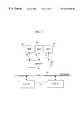
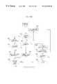
- FIG. 1is a block diagram of a network system in which the present method is implemented
- FIG. 2is a block diagram of a network system with a peripheral server attached to a plurality of peripherals in which the present method is implemented;
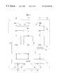
- FIG. 3is a block diagram of the server in FIG. 1 including a scan gateway;
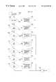
- FIG. 4 A and FIG. 4Bare flowcharts describing the steps involved in establishing a connection to one of the server test ports and issuing test port commands in accordance with an embodiment of the invention
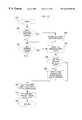
- FIG. 5is a flowchart describing the steps involved in establishing a network scan connection to a scan gateway in accordance with an embodiment of the invention
- FIG. 6is a flowchart describing the steps involved in performing a Backplane Performance test in accordance with an embodiment of the invention
- FIG. 7is a flowchart describing the steps involved in performing a Frontplane Performance test in accordance with an embodiment of the invention.
- FIG. 8is a flowchart describing the steps involved in performing a Backplane Toggle test in accordance with an embodiment of the invention.
- FIG. 9is a flowchart describing the steps involved in processing test port commands in accordance with an embodiment of the invention.
- FIG. 10is a flowchart describing the steps involved in processing a Status Query command in accordance with an embodiment of the invention.
- FIG. 11is a flowchart describing the steps involved in processing a command to modify the maximum segment size in accordance with an embodiment of the invention
- FIG. 12is a flowchart describing the steps involved in processing a Cancel command in accordance with an embodiment of the invention.
- FIG. 13is a flowchart describing the steps involved in processing a Reset command in accordance with an embodiment of the invention.
- FIG. 14is a flowchart describing the steps involved in processing a Backplane Performance command in accordance with an embodiment of the invention.
- FIG. 15is a flowchart describing the steps involved in processing a Frontplane Performance command in accordance with an embodiment of the invention.
- FIG. 16 A and FIG. 16Bare flowcharts describing the steps involved in processing a Backplane Toggle command in accordance with an embodiment of the invention.
- BIOBitronics Input/Output
- the present inventionis directed to a method for testing a data path or gateway in a dedicated peripheral server for passing data to and from a network peripheral or a multifunction peripheral (MFP).
- the methodallows the network interface portion and the peripheral interface portion of the gateway to be tested independently and under different data packet size requirements.
- the present inventionis directed to a method for testing a data path of a server that is operably connected between at least one peripheral device and a network.
- the data pathis adapted to transmit data between the peripheral device and the network.
- the methodincludes first testing one of the peripheral interface portion and the network interface portion of the data path.
- a status reportis generated indicating the test results of the first test.
- a separate testis performed on the other of the peripheral interface portion and the network interface portion of the data path.
- a status reportis then generated indicating the test results of the second test.
- the network in which the present method is implementedis generally indicated at 10 , and includes a plurality of client computers 12 (two shown) and a dedicated peripheral server 14 connected to the network.
- a multi-function peripheral (MFP) 18which performs printing, scanning and other functions is connected to the peripheral server 14 via a parallel cable 19 .
- server 14may also be connected to a single-function peripheral such as a printer or a scanner, or to a plurality of multi-function peripherals (MFP) 18 , printers or scanners, each connected to the server 14 by a separate parallel cable 19 .
- MFPmulti-function peripheral
- printers or scannersprinters or scanners
- the preferred peripheral server 14is adapted to be operably connected to the MFP 18 , and includes a Bitronics I/O (BIO) interface 20 which connects to the MFP 18 , and a transmission control protocol (TCP) and/or sequenced packet exchange (SPX) interface 22 to the network 10 .
- BIOBitronics I/O
- TCPtransmission control protocol
- SPXsequenced packet exchange
- SGWscan gateway
- PGWprint gateway
- a firmwarewhich preferably employs Peripheral Management Language (PML) 28 to control the functions of the MFP 18 .
- PMLPeripheral Management Language
- the TCP/SPX interface 22 on the preferred server 14provides network connectivity via a plurality of network ports, including SGW scan ports 31 , SGW test ports 32 , PGW print ports 33 and other ports 34 .
- SGW scan ports 31SGW scan ports 31
- SGW test ports 32SGW test ports 32
- PGW print ports 33PGW print ports 33
- other ports 34other network protocols and port combinations.
- the present methodis generally directed to any gateway of the server 14 , it is most preferably directed to the scan gateway (SGW) 24 , which transmits scan data between the MFP 18 and the network 10 . As such, the following method is described with respect to the SGW 24 .
- a Backplane Performance (BP) testmeasures the amount of time required for the server 14 to receive a specified number of bytes of scan data from the MFP 18 via the BIO interface 20 . In this test, the data is discarded once received to eliminate internal processing time.
- a status report containing the test results of the BP testis sent via a test port connection to the network 10 upon completion of the test.
- Another testis a Frontplane Performance (FP) test which causes the server 14 to generate a specified number of bytes of test data and send them on the TCP/SPX interface 22 to the network 10 . Similar to the BP test, a status report is generated when the test is completed.
- FPFrontplane Performance
- the target (maximum) byte countsare specified at the start of each test by means of command parameters.
- Yet another testis a Backplane Toggle (BT) test which measures the ability of the peripheral server 14 to quickly and repeatedly open and close Multiple Logical Channel (MLC) 30 connections with the MFP 18 over the parallel cable 19 (best shown in FIG. 1 ).
- MLC 30is a parallel port protocol that splits a single parallel connection into several “logical channels” which can then be used for command data, scan data, print data, etc., and that the required functionality can be realized using other multiplexing transport protocols besides MLC.
- the above described testscan be performed at different maximum segment sizes (MSS), i.e., the maximum number of data bytes per packet used when passing data from the MFP 18 to the network 10 .
- MSSmaximum segment sizes
- the performance (and reactions) of the server 14can be measured under various external network conditions without actually having to produce those conditions in the network 10 .
- the TCP/SPX interface 22provides a SGW test port 32 (best shown in FIG. 3) which supports one or more network connections.
- SGW test port 32(best shown in FIG. 3) which supports one or more network connections.
- FIG. 4Acommunication with a SGW test port 32 is started (Block 35 ) when a client 12 sends a signal to the peripheral server 14 through a temporary connection in the SGW test port, requesting it to accept a connection (Block 36 ) on the SGW test port 32 for the purposes of sending commands and receiving status reports.
- the peripheral server 14checks to see if a connection is available (Block 38 ).
- the serversends a response back to the client 12 , indicating that the test port 32 is unavailable (Block 42 ) and closes the connection through which the connection request had been made (Block 44 ). If an error prevents the server from sending a connection response (Block 40 ), the server simply closes the temporary test port connection (Block 44 ) without sending a response to the client. In both cases, communication over the test port connection is terminated (Block 46 ).
- the server 14determines that the SGW test port 32 is available (Block 38 )
- the serverperforms test port initialization (Block 50 ) if this is the first open SGW test port connection (Block 48 ), sends a successful connection response (Block 52 ) back to the client, and the previously temporary connection becomes a successful test port connection.
- the responses sent by the serverare comprised of two ASCII digits sent on the newly opened connection and indicate the following, for example:
- test port connectionis disconnected after “01” response is issued by the server 14 or when there is a general error (Block 44 ).
- commands issued by the client 12 and responses generated by the server 14are transmitted via this connection.
- the server 14determines whether or not the command is valid (Block 62 ) and sends a response to the client 12 indicating either that the command has been accepted (Block 66 ) or specifying why the command is being rejected (Block 64 ).
- the command responsesare comprised of two ASCII digits, which indicate the following responses, for example:
- the server 14After notifying the client 12 that a valid command has been accepted (Block 66 ), the server 14 begins processing the command (Block 68 and FIG. 9 ). Some commands cause the server 14 to generate one or more status reports when processing completes, but the client 12 is not required to wait for the server 14 to finish processing before issuing more SGW test port commands. After receiving either a successful (Block 66 ) or negative (Block 64 ) response to a command, the client can continue communicating (Block 70 ) by issuing new SGW test port commands (Block 54 ) or waiting for (Block 58 ) and receiving status reports (Block 59 ) from the server 14 for one or more earlier commands (Block 56 ).
- the client 12terminates communication (Block 70 ) by closing the SGW test port connection (Block 74 ). This may not be necessary (Block 72 ) if the connection has already been closed, such as in the case of a Reset command (FIG. 13) being received on another open SGW test port connection. If any SGW test port commands that were initiated by the client 12 are still running or pending (Block 76 ) at the time the SGW test port 32 is closed, the server 14 cancels the running/pending commands (Block 78 ). At this point, the SGW test port connection no longer exists (Block 80 ).
- a data pathis established between a client 12 and a MFP 18 through a SGW scan gateway 24 (best shown in FIG. 3) on the peripheral server 14 , preferably using a variation of a method described in commonly assigned U.S. patent application Ser. No. 09/163,496 filed Sep. 30, 1998 and entitled “Network Scanner Contention Handling Method,” for example, which is incorporated by reference herein.
- FIG. 5describes the steps involved in establishing a data path in accordance with an embodiment of the invention.
- the client 12sends a signal over the network 10 to a selected one of the SGW scan ports 31 , requesting it to accept a network scan connection (Block 84 ). If the SGW scan port 31 is busy or unavailable (Block 86 ), the server 14 sends a response back to the client 12 indicating same (Block 90 ) and closes the connection between the selected SGW scan port 31 and the network 10 (Block 92 ). If an error prevents the server 14 from sending a connection response (Block 88 ), the server simply closes the SGW scan port connection (Block 92 ) without sending a response to the client.
- the initial connection between the SGW scan port 31 and the network 10is terminated (Block 92 ). If, however, the server 14 determines that the SGW scan port 31 is available (Block 86 ), the server sets the maximum segment size (MSS) for the SGW scan port to either the “Test MSS” value if a SGW test port connection is already open (Block 94 and Block 96 ), or uses the default MSS value that was received from the network 10 if there are no other open, SGW test port connections (Block 98 ).
- MSSmaximum segment size
- the server 14After setting the MSS value, the server 14 sends a successful connection response (Block 100 ) back to the client 12 , and the connection between the selected SGW scan port 31 and the network 10 remains open for communication, completing establishment of the data path (Block 102 ).
- the responses sent by the server 14(Block 90 and Block 100 ) are comprised of two ASCII digits sent on the newly opened SGW scan port connection and indicate the following, for example:
- FIG. 6the method for conducting the Backplane Performance (BP) test in accordance with the invention is described.
- the client 12Prior to issuing a Backplane Performance (BP) test command (Block 130 ), the client 12 must open one or more SGW scan port 31 connections (Block 110 and Block 124 ; and FIG. 5) and a SGW test port 32 connection (Block 116 and Block 118 ; and FIG. 4A) to the TCP/SPX interface 22 on the server 14 .
- the MSScan only be set at connection establishment time.
- the clientmust open the SGW test port 32 connection (Block 118 ) and issue the SGW test port command to modify the scan port MSS value (Block 120 ) before opening the SGW scan port connection (Block 122 and Block 124 ); otherwise, the ports 32 can be opened in either order shown in Blocks 108 , 110 , 116 , 122 and 124 .
- the client 12sends any commands necessary to set up scan jobs on the specified SGW scan port connections (Blocks 112 , 114 , 126 and 128 ).
- the setup commandsare sent before sending the BP test command because the BP test starts running as soon as data is received from the backplane BIO interface 20 . If the test were started before setting up the scan jobs, responses to the setup commands could incorrectly cause the test to start running, resulting in inaccurate throughput measurements.
- the client 12After the client 12 has established the required connections and set up the scan jobs, the client 12 sends a BP command to the server 14 on the SGW test port connection 32 and waits for a response (Block 130 ), as described earlier in FIG. 4 B.
- the BP commandcan include parameters to specify the peripheral port(s) and number of bytes to be received during the test.
- the client 12After receiving a successful response to the BP command, the client 12 sends the necessary commands to start a scan job on each of the specified SGW scan port connections (Block 132 ). As the test completes on each of the specified SGW scan port connections, the server 14 generates a status report providing results of the BP test. After receiving the status reports (Block 134 ), the client 12 sends a signal to the server 14 to close the SGW test port 32 and SGW scan port 31 connections on the TCP/SPX interface 22 (Block 136 ). The BP test is ended at this point (Block 138 ).
- FIG. 7the Frontplane Performance (FP) test according to the invention is described.
- the client 12Prior to issuing a Frontplane Performance (FP) test command (Block 158 ), the client 12 must open one or more SGW scan port 31 connections (Block 146 and Block 158 ; and FIG. 5) and a SGW test port 32 connection (Block 148 and Block 150 ; and FIG. 4A) to the TCP/SPX interface 22 on the server 14 .
- the MSScan only be set at connection establishment time.
- the clientif a modified MSS value is to be used during the test (Block 142 ), then the client must open the SGW test port 32 connection (Block 150 ) and issue the SGW test port command to modify the scan port MSS value (Block 152 ) before opening the SGW scan port connection (Block 154 and Block 156 ); otherwise, the ports can be opened in either order shown in Blocks 144 , 146 , 148 , 154 and 156 .
- the client 12After the client 12 has established the required connections, the client 12 sends a FP command to the server 14 on the SGW test port connection 32 and waits for a response (Block 158 ), as described earlier with reference to FIG. 4 B.
- the FP commandcan include parameters to specify peripheral (MFP) port(s) and the number of test bytes to be generated and sent by the server 14 to the network 10 on each SGW scan port connection during the test.
- the client 12After receiving a successful response to the FP command, the client 12 sends at least one byte of data to the server 14 on each of the specified TCP/SPX interface 22 SGW scan port 31 connections (Block 160 ), to signal the server 14 to start sending test data to the network 10 on the connection.
- the server 14As the test completes on each of the specified SGW scan ports (Block 162 ), the server 14 generates a status report providing results of the FP test. After receiving the status reports (Block 162 ), the client 12 sends a signal to the server 14 to close the SGW test port 32 and the SGW scan port 31 connections on the TCP/SPX interface 22 (Block 164 ). The FP test is ended at this point (Block 166 ).
- FIG. 8describes a Backplane Toggle (BT) test in accordance with the invention.
- the BT testmeasures the ability of the peripheral server 14 to quickly and repeatedly open and close the Multiple Logical Channel (MLC) 30 connections with the MFP 18 over the parallel cable 19 (best shown in FIGS. 2 and 3 ).
- MLCMultiple Logical Channel
- the client 12prior to issuing a BT test command (Block 186 ), the client 12 must open one or more SGW scan port 31 connections (Block 174 and Block 184 ; and FIG. 5) and a SGW test port 32 connection (Block 176 and Block 178 ; and FIG. 4A) to the TCP/SPX interface 22 on the server 14 .
- the clientmust open the SGW test port 32 connection (Block 178 ) and issue the SGW test port command to modify the scan port MSS value (Block 180 ) before opening the SGW scan port connections (Block 182 and Block 184 ); otherwise, the ports can be opened in either order shown in Blocks 172 , 174 , 176 , 182 and 184 .
- the client 12After the client 12 has established the required connections, the client 12 sends a BT command to the server 14 on the SGW test port connection 32 and waits for a response (Block 186 ), as described earlier in FIG. 4 B.
- the BT commandcan include parameters to specify the peripheral port(s), the number of times to open (toggle) the MLC connection 30 on each port, and the delay, if any, after an open failure on an MLC connection 30 .
- the server 14After sending a positive response to the BT command (Block 186 ), the server 14 begins toggling, i.e., opening and closing, the MLC connection 30 between the BIO interface 20 and the MFP 18 on each specified port.
- the clientmust terminate the BT test by sending a Cancel (CA) command on the SGW test port 32 connection, or by closing the SGW test port 32 or SGW scan port 31 connections (Block 190 ). Otherwise, the server 14 will terminate the BT test on each specified port after the MLC connection 30 has been opened (toggled) the specified number of times. As the test completes on each of the specified SGW scan ports (Block 192 ), the server 14 generates a status report providing results of the FP test.
- CACancel
- the client 12After receiving the status reports (Block 192 ), the client 12 sends a signal to the server 14 to close the SGW test port 32 and the SGW scan port 31 connections on the TCP/SPX interface 22 (Block 194 ). The FP test is ended at this point (Block 196 ).
- the server 14In the above-described tests, the server 14 generates a status report for each port being tested and sends it to the client on the SGW test port 32 connection at the conclusion of the test. It should also be noted that status reports will be generated by the server 14 in response to Status Query (SQ), Cancel (CA) and Reset (RE) commands received from the client 12 on a SGW test port 32 connection. Whether generated upon the completion of a test or in response to one of the above commands, the status report provides the client with information concerning the performance or the status of the SGW 24 of the peripheral server 14 . In the preferred embodiment, the status report contains the following fields, where the “x” characters shown in the field column are replaced by values in the actual status reports:
- Field Description SR2-byte identifier indicating start of status report.
- Px Peripheral (MFP) port number (0-2) associated with this status report.
- MSSCxxx Most recent value received in a test port MS command for this peripheral port.
- IDxx 2-byte test identifier (BP, FP, BT, or ⁇ null>) associated with current or most recent test.
- BUFPSxx Max number of buffers that can be sent in a single thread of execution (applies to FP test only).
- TARxxx Target value: For FP or BP test, target (maximum) byte count.
- CURxxx Current value: For FP or BP test, current byte count.
- PCTxx Percent completion of current or most recent test.
- V1xxx Test-specific value 1: For FP test, MSS value received from network on scan connection. For BT test, number of negative acknowledgments received for peripheral open requests. Does not apply to the other tests.
- the processing of SGW test port commandsis performed by a firmware 25 provided within the SGW 24 of the server 14 (Block 68 ).
- the server 14After receiving a valid SGW test port command (Block 62 ), the server 14 sends a success response to the client (Block 66 ) and then processes the command (FIG. 4B, Block 68 ; and FIG. 9, Block 198 ).
- the server 14first identifies the individual command to be processed.
- Valid SGW test port commandsinclude Status Query (SQ) (Block 200 ), Max Segment Size (MS) (Block 204 ), Cancel (CA) (Block 208 ), Reset (RE) (Block 212 ), Backplane Performance (BP) (Block 216 ), Frontplane Performance (FP) (Block 220 ) and Backplane Toggle (BT) (Block 224 ) commands.
- SQStatus Query
- MSMax Segment Size
- CACarcel
- REReset
- BPBackplane Performance
- FPFrontplane Performance
- BTBackplane Toggle
- the server 14is available to accept new commands from clients (FIG. 4B; and Block 228 of FIG. 9) while other commands are being processed (Blocks 202 , 206 , 210 , 214 , 218 , 222 and 226 ).
- the SQ commandcauses the server 14 to send a status report for each port specified by the command.
- the server 14collects status for the first requested port 31 (Block 232 ). If a test is currently pending or running on the requested port 31 (Block 234 ), the server generates and sends a status report of the currently pending/running test (Block 238 ); otherwise, the server 14 generates and sends a status report of the requested port's most recently completed test (Block 236 ) or an empty report if no tests have been run.
- the status report formatis the same as described earlier, and the report is sent to the client that issued the SQ command, on the same SGW test port 32 connection. If additional ports 31 were specified by the SQ command (Block 240 ), the above steps are repeated for each additional port (Block 242 ), until a status report has been sent for all of the requested ports. After a status report for the last requested port 31 has been sent (Block 240 ), the SQ command processing is completed (Block 244 ).
- the maximum segment size of the data packetscan be modified independently of the external network conditions, so that the performance of the server 14 can be measured under different conditions.
- the MS commandcauses the server 14 to change the MSS value on the specified ports 31 .
- the MSS valueis the maximum size of packets sent by the TCP/SPX interface 22 to the network 10 on SGW scan port connections, and also the maximum allowable size of packets received by the BIO interface 20 from peripherals on the MLC connections 30 .
- the value specified in the MS commandis stored as a Test MSS value that does not affect currently open MLC and SGW scan port connections 30 , 31 but is applied to all subsequently opened connections on the specified ports.
- the server 14changes the Test MSS value on the first requested port 31 (Block 248 ). If the MSS value specified by the MS command is zero (Block 250 ), the default MSS calculation will be performed for each subsequent connection on the port 31 (Block 254 ); otherwise, the new Test MSS value will be used as the MSS value for all subsequent connections on the port (Block 252 ).
- the CA commandcauses the server 14 to cancel any tests currently pending or running on ports 31 specified by the command.
- the serverstarts the CA command processing (Block 262 ) with the first requested port 31 (Block 264 ). If a test is currently pending or running on the requested port 31 (Block 266 ), the server cancels the test (Block 268 ) and sends a status report to the client that initiated the test (Block 270 ), indicating that the test was cancelled.
- the RE commandcauses the server 14 to close all the SGW test port 32 connections other than the one that received the Reset command, cancel all tests currently pending or running on any ports, reinitialize the status report values on all ports, and clear any Test MSS values that were set by previous MS commands.
- the server 14starts the RE command processing (Block 278 ) by determining whether any other SGW test port connections are open (Block 280 ), and if so, closing the other SGW test port connections (Block 282 ). If tests are pending or running on any ports (Block 284 ), the server 14 cancels the pending/running tests (Block 286 ). If the SGW test port 32 connection used to initiate any of the tests that were cancelled still exists (Block 288 ), the server 14 sends a status report on the SGW test port connection to the client 12 that initiated the test (Block 290 ), indicating that the test was cancelled. The server 14 then clears the test status information on all ports (Block 292 ), so that subsequent status reports will indicate that no tests have been run. Finally, the server 14 sets the Test MSS value to default on all ports (Block 294 ), so that the default MSS calculations will be used on subsequent scan connections, and the RE command processing is completed (Block 296 ).
- the BP testmeasures the amount of time required for the server 14 to receive a specified number of bytes of scan data from the MFP 18 via the BIO interface 20 . In this test, the data is discarded once received to eliminate internal processing time.
- the server 14starts the BP command processing (Block 298 ) with the first requested port 31 (Block 300 ) by setting the port's max count value to the number of bytes specified in the BP command and initializing the port's current byte count to zero (Block 302 ).
- the serveralso initializes the port 31 to the test pending state (Block 304 ). If additional ports were specified by the BP command (Block 306 ), the above steps are repeated for each additional port (Block 308 ), until all of the requested ports have been initialized to the test pending state (Block 306 ).
- each port 31remains in the test pending state until the server 14 receives at least one byte of data from the MFP 18 on the port's BIO interface 20 (Block 310 ). If the port 31 is in pending state at the time data is received on the BIO interface 20 (Block 312 ), the server 14 sets the port to the running state (Block 314 ). If the port 31 is in either test pending or test running state at the time data is received on the BIO interface 20 , the server 14 adds the number of bytes received to the port's current byte count (Block 316 ).
- the server 14sets the port to test completed state (Block 320 ) and sends a status report on the SGW test port 32 connection to the client that initiated the test (Block 322 ).
- the preferred status reportincludes the number of bytes received on the BIO interface 20 and the amount of time that elapsed between receiving the first and last byte. If the tests have not completed on all of the specified ports 31 (Block 324 ), the server 14 continues waiting for data to be received from the MFP 18 on the BIO interface 20 for the specified ports, and when data is received, resumes the above process (starting at Block 312 ). Otherwise, if the tests have completed on all of the specified ports 31 (Block 324 ), BP command processing is completed (Block 326 ).
- the FP testcauses the server 14 to generate a specified number of bytes of test data and send them on the TCP/SPX interface 22 to the network 10 .
- the server 14starts the FP command processing (Block 328 ) with the first requested port 31 (Block 330 ), by setting the port's max count value to the number of bytes specified in the FP command and initializing the port's current byte count to zero (Block 332 ).
- the serveralso initializes the port 31 to the test pending state (Block 334 ). If additional ports 31 were specified by the FP command (Block 336 ), the above steps are repeated for each additional port (Block 338 ), until all of the requested ports have been initialized to the test pending state (Block 336 ).
- each port 31remains in the test pending state until the server 14 receives at least one byte of data from the network on the TCP/SPX interface 22 for the pending test's SGW scan port 31 (Block 340 ). If the port 31 is in pending state at the time data is received on the SGW scan port 31 (Block 342 ), the server 14 discards the data and sets the port to the running state (Block 344 ).
- the server 14sends a packet on the port's TCP/SPX interface 22 (Block 346 ) and adds the number of bytes sent to the port's current byte count (Block 348 ). If the port's current byte count is greater than or equal to the port's max count value (Block 350 ), the server 14 sets the port to the test completed state (Block 352 ) and sends a status report on the SGW test port 32 connection to the client that initiated the test (Block 354 ). It should be noted that in the preferred embodiment of the invention, if the FP command specifies a max byte count of zero, the server 14 treats the max count value as infinite, and thus, continues sending packets until the FP command is canceled.
- the preferred status reportincludes the number of bytes sent on the SGW scan port 31 to the network 10 and the amount of time that elapsed between sending the first and last byte. If the tests have not completed on all of the specified ports 31 (Block 356 ), the server 14 continues waiting for data to be received from the network 10 on one of the ports in the test pending state (Block 340 ), or a port in the test running state to become ready to send another packet to the network 10 (Block 344 ). When either of those conditions occur, the server 14 repeats the above steps, starting at Block 340 . Otherwise, if the tests have completed on all of the specified ports 31 (Block 356 ), FP command processing is completed (Block 358 ).
- the Backplane Toggle (BT) testmeasures the ability of the peripheral server 14 to quickly and repeatedly open and close Multiple Logical Channel (MLC) 30 connections with the MFP 18 over the parallel cable 19 (best shown in FIGS. 1 and 3 ).
- the server 14starts the BT command processing (Block 360 ) with the first requested port (Block 362 ), by setting the port's max count value to the max open (toggle) count specified in the BT command and initializing the port's current toggle count to zero (Block 364 ).
- the serveralso initializes the port to the test running state (Block 366 ).
- the server 14closes the MLC connection (Block 376 ) and begins processing the next requested port 31 (Block 378 ), starting again at Block 374 ; otherwise, the server sends an MLC open request to the MFP 18 (Block 380 ). If the MLC open request is successful (Block 382 ), the server increments the port's successful open count (Block 384 ), otherwise, it increments the port's count of open failures (Block 386 ).
- the preferred embodiment of the server 14will not attempt another open request on the failing port for a specified delay period if the BT command specified a non-zero delay value; other ports 31 will continue to be toggled, however. If the number of open attempts (success count plus failure count) is greater than or equal to the BT command's max toggle value (Block 388 ), the server 14 sets the port 31 to test completed state (Block 390 ) and sends a status report on the SGW test port 32 connection to the client that initiated the test (Block 392 ).
- the server 14treats the max toggle value as infinite, and thus, continues toggling the MLC connections 30 until the BT command is canceled.
- the preferred status reportincludes the number of opens that completed successfully and the number of opens that failed, and the amount of time that elapsed between the first and last open attempt. If the tests have not completed on all of the specified ports 31 (Block 394 ), the server 14 resumes processing with the next port that is in test running state (Block 378 ), starting again at Block 374 . Otherwise, if the tests have completed on all of the specified ports 31 (Block 394 ), BT command processing is complete (Block 396 ).
Landscapes
- Engineering & Computer Science (AREA)
- Computer Networks & Wireless Communication (AREA)
- Signal Processing (AREA)
- Computer And Data Communications (AREA)
Abstract
Description
| Response | Description | ||
| “00” | Successful connection. | ||
| “01” | Too many test port connections. | ||
| No Response | General Error. | ||
| Response | Description | ||
| “00” | Command Accepted. | ||
| “71” | Command Rejected: Unknown Command. | ||
| “72” | Command Rejected: Another command is already | ||
| Pending/Running | |||
| “73” | Command Rejected: Requested command cannot be | ||
| started in the current state. | |||
| “74” | Command Rejected: Command syntax error. | ||
| “75” | Command Rejected: Bad port number. | ||
| “79” | Command Rejected: General Error. | ||
| Response | Description | ||
| “00” | Successful connection. | ||
| “01” | Scanner Busy. | ||
| “02” | Scanner Unavailable. | ||
| No Response | General Error. | ||
| Field | Description |
| SR | 2-byte identifier indicating start of status report. |
| P=x | Peripheral (MFP) port number (0-2) associated with this |
| status report. | |
| MSSC=xxx | Most recent value received in a test port MS command for |
| this peripheral port. | |
| ID=xx | 2-byte test identifier (BP, FP, BT, or <null>) |
| associated with current or most recent test. | |
| ST=xx | Status of current or most recent test: |
| “00” - Test Completed or Idle | |
| “01” - Test Pending | |
| “02” - Test Running | |
| RES=xx | Result of current or most recent test: |
| “00” - Success | |
| “01” - Failure due to Network Disconnect | |
| “02” - Failure due to Scanner Reset | |
| “03” - Test Canceled | |
| “04” - Failure due to Idle Timeout | |
| “05” - Failure due to SGW Test Port disconnect | |
| “06” - Failure due to error while sending data to network | |
| “FF” - Failure due to General Error | |
| MSS=xxx | Max segment size used during the current or most |
| recent test. | |
| BUF=xx | Number of buffers currently outstanding |
| (applies to FP test only). | |
| BUFPS=xx | Max number of buffers that can be sent in a single |
| thread of execution (applies to FP test only). | |
| TAR=xxx | Target value: |
| For FP or BP test, target (maximum) byte count. | |
| For BT test, target (maximum) number of peripheral | |
| open requests. | |
| CUR=xxx | Current value: |
| For FP or BP test, current byte count. | |
| For BT test, number of positive acknowledgments received | |
| for peripheral open requests. | |
| PCT=xx | Percent completion of current or most recent test. |
| V1=xxx | Test-specific value 1: |
| For FP test, MSS value received from network on scan | |
| connection. | |
| For BT test, number of negative acknowledgments received | |
| for peripheral open requests. | |
| Does not apply to the other tests. | |
| V2=xx | Test specific value 2: |
| For FP test, number of times max buffers not available | |
| when attempting to send data. | |
| For BT test, value of time duration (clock ticks) parameter | |
| BT command. | |
| Does not apply to the other tests. | |
| T=xxxx | Elapsed time (in system clock ticks) for current or |
| most recent test. | |
| R=xxxx | Rate: |
| For FP or BP test, estimated data rate in bytes/sec. | |
| For BT test, number of peripheral open requests/sec. | |
Claims (43)
Priority Applications (1)
| Application Number | Priority Date | Filing Date | Title |
|---|---|---|---|
| US09/333,362US6618360B1 (en) | 1999-06-15 | 1999-06-15 | Method for testing data path of peripheral server devices |
Applications Claiming Priority (1)
| Application Number | Priority Date | Filing Date | Title |
|---|---|---|---|
| US09/333,362US6618360B1 (en) | 1999-06-15 | 1999-06-15 | Method for testing data path of peripheral server devices |
Publications (1)
| Publication Number | Publication Date |
|---|---|
| US6618360B1true US6618360B1 (en) | 2003-09-09 |
Family
ID=27788912
Family Applications (1)
| Application Number | Title | Priority Date | Filing Date |
|---|---|---|---|
| US09/333,362Expired - LifetimeUS6618360B1 (en) | 1999-06-15 | 1999-06-15 | Method for testing data path of peripheral server devices |
Country Status (1)
| Country | Link |
|---|---|
| US (1) | US6618360B1 (en) |
Cited By (61)
| Publication number | Priority date | Publication date | Assignee | Title |
|---|---|---|---|---|
| US20020097263A1 (en)* | 2001-01-25 | 2002-07-25 | Nec Corporation | File delevery system and method for delivering file of style depending on request of each user terminal |
| US20020154328A1 (en)* | 2001-04-18 | 2002-10-24 | Eiichi Sato | Printing control apparatus and printing control method enabling image forming apparatus to adapt various printing data formats |
| US20030097469A1 (en)* | 2001-11-19 | 2003-05-22 | Blair Timothy P. | Method and system for gathering data using automatic appliance failover |
| US20050058083A1 (en)* | 2003-09-17 | 2005-03-17 | Rivulet Communications, Inc. | Empirical scheduling of network packets using coarse and fine testing periods |
| US20050073716A1 (en)* | 2003-10-07 | 2005-04-07 | Canon Kabushiki Kaisha | Data processing apparatus, method, and program |
| US20050086362A1 (en)* | 2003-09-17 | 2005-04-21 | Rogers Steven A. | Empirical scheduling of network packets |
| US20050094642A1 (en)* | 2003-10-31 | 2005-05-05 | Rogers Steven A. | Endpoint packet scheduling system |
| US20050111357A1 (en)* | 2003-11-25 | 2005-05-26 | Rogers Steven A. | Internet endpoint system |
| US20060077981A1 (en)* | 2004-10-13 | 2006-04-13 | Rivulet Communications, Inc. | Network connection device |
| US20060171414A1 (en)* | 2004-11-24 | 2006-08-03 | Behnam Katibian | Systems and methods for digital data transmission rate control |
| US20070071026A1 (en)* | 2005-09-23 | 2007-03-29 | Rivulet Communications, Inc. | Compressed video packet scheduling system |
| US20070189176A1 (en)* | 2006-02-14 | 2007-08-16 | Finisar Corporation | Random data compression scheme in a network diagnostic component |
| US20070189175A1 (en)* | 2006-02-14 | 2007-08-16 | Finisar Corporation | Capture timing and negotiation data with repeat counts in a networking diagnostic component |
| US20070192501A1 (en)* | 2006-01-30 | 2007-08-16 | Juniper Networks, Inc. | Determining connectivity status for unnumbered inerfaces of a target network device |
| US20070206509A1 (en)* | 2006-03-03 | 2007-09-06 | Finisar Corporation | Capture rcdt and sntt sas speed negotiation decodes in a network diagnostic component |
| US7313598B1 (en)* | 2002-06-13 | 2007-12-25 | Cisco Technology, Inc. | Method and apparatus for partial replication of directory information in a distributed environment |
| US20080152143A1 (en)* | 2006-12-20 | 2008-06-26 | Daniel Charles Estelle | Apparatus, system, and method for checking the health of encryption key managers |
| US20080189641A1 (en)* | 2006-02-14 | 2008-08-07 | Finisar Corporation | Show oob and speed negotiation data graphically in a network diagnostic component |
| US7523215B1 (en)* | 2002-01-14 | 2009-04-21 | Xilinx, Inc. | Method and apparatus for configuring data transmissions within a micro-area network |
| US20090207752A1 (en)* | 2008-02-19 | 2009-08-20 | Embarq Holdings Company, Llc | System and method for authorizing threshold testing within a network |
| US20100260055A1 (en)* | 2003-12-08 | 2010-10-14 | Qualcomm Incorporated | High data rate interface with improved link synchronization |
| US20110113290A1 (en)* | 2009-11-09 | 2011-05-12 | International Business Machines Corporation | Method and system for testing configuration of environments |
| US8339973B1 (en) | 2010-09-07 | 2012-12-25 | Juniper Networks, Inc. | Multicast traceroute over MPLS/BGP IP multicast VPN |
| US8472346B1 (en) | 2007-06-08 | 2013-06-25 | Juniper Networks, Inc. | Failure detection for tunneled label-switched paths |
| US20130163445A1 (en)* | 2011-12-22 | 2013-06-27 | Partha Majumdar | Testing TCP Connection Rate |
| US8539119B2 (en) | 2004-11-24 | 2013-09-17 | Qualcomm Incorporated | Methods and apparatus for exchanging messages having a digital data interface device message format |
| US8606946B2 (en) | 2003-11-12 | 2013-12-10 | Qualcomm Incorporated | Method, system and computer program for driving a data signal in data interface communication data link |
| US8625625B2 (en) | 2004-03-10 | 2014-01-07 | Qualcomm Incorporated | High data rate interface apparatus and method |
| US8630305B2 (en) | 2004-06-04 | 2014-01-14 | Qualcomm Incorporated | High data rate interface apparatus and method |
| US8635358B2 (en) | 2003-09-10 | 2014-01-21 | Qualcomm Incorporated | High data rate interface |
| US8645566B2 (en) | 2004-03-24 | 2014-02-04 | Qualcomm Incorporated | High data rate interface apparatus and method |
| US8650304B2 (en) | 2004-06-04 | 2014-02-11 | Qualcomm Incorporated | Determining a pre skew and post skew calibration data rate in a mobile display digital interface (MDDI) communication system |
| US8667363B2 (en) | 2004-11-24 | 2014-03-04 | Qualcomm Incorporated | Systems and methods for implementing cyclic redundancy checks |
| US8681817B2 (en) | 2003-06-02 | 2014-03-25 | Qualcomm Incorporated | Generating and implementing a signal protocol and interface for higher data rates |
| US8687658B2 (en) | 2003-11-25 | 2014-04-01 | Qualcomm Incorporated | High data rate interface with improved link synchronization |
| US8694663B2 (en) | 2001-09-06 | 2014-04-08 | Qualcomm Incorporated | System for transferring digital data at a high rate between a host and a client over a communication path for presentation to a user |
| US8692839B2 (en) | 2005-11-23 | 2014-04-08 | Qualcomm Incorporated | Methods and systems for updating a buffer |
| US8694652B2 (en) | 2003-10-15 | 2014-04-08 | Qualcomm Incorporated | Method, system and computer program for adding a field to a client capability packet sent from a client to a host |
| US8692838B2 (en) | 2004-11-24 | 2014-04-08 | Qualcomm Incorporated | Methods and systems for updating a buffer |
| US8705571B2 (en) | 2003-08-13 | 2014-04-22 | Qualcomm Incorporated | Signal interface for higher data rates |
| US8705521B2 (en) | 2004-03-17 | 2014-04-22 | Qualcomm Incorporated | High data rate interface apparatus and method |
| US8723705B2 (en) | 2004-11-24 | 2014-05-13 | Qualcomm Incorporated | Low output skew double data rate serial encoder |
| US8730069B2 (en) | 2005-11-23 | 2014-05-20 | Qualcomm Incorporated | Double data rate serial encoder |
| US8745251B2 (en) | 2000-12-15 | 2014-06-03 | Qualcomm Incorporated | Power reduction system for an apparatus for high data rate signal transfer using a communication protocol |
| US8756294B2 (en) | 2003-10-29 | 2014-06-17 | Qualcomm Incorporated | High data rate interface |
| US8769152B2 (en) | 2006-02-14 | 2014-07-01 | Jds Uniphase Corporation | Align/notify compression scheme in a network diagnostic component |
| US8797886B1 (en) | 2006-01-30 | 2014-08-05 | Juniper Networks, Inc. | Verification of network paths using two or more connectivity protocols |
| US8873584B2 (en) | 2004-11-24 | 2014-10-28 | Qualcomm Incorporated | Digital data interface device |
| US8902780B1 (en) | 2012-09-26 | 2014-12-02 | Juniper Networks, Inc. | Forwarding detection for point-to-multipoint label switched paths |
| US8953460B1 (en) | 2012-12-31 | 2015-02-10 | Juniper Networks, Inc. | Network liveliness detection using session-external communications |
| US20150172118A1 (en)* | 2013-12-18 | 2015-06-18 | Alpha Networks Inc. | Method for automatically configuring gateway device |
| US20150254153A1 (en)* | 2014-03-07 | 2015-09-10 | Avision Inc. | Peripheral apparatus management system, peripheral apparatus operating system and sharing system thereof |
| US20150333866A1 (en)* | 2014-05-15 | 2015-11-19 | International Business Machines Corporation | Link speed downshifting for error determination and performance enhancements |
| US9258234B1 (en) | 2012-12-28 | 2016-02-09 | Juniper Networks, Inc. | Dynamically adjusting liveliness detection intervals for periodic network communications |
| US9769017B1 (en) | 2014-09-26 | 2017-09-19 | Juniper Networks, Inc. | Impending control plane disruption indication using forwarding plane liveliness detection protocols |
| US20180206136A1 (en)* | 2017-01-17 | 2018-07-19 | Tutela Technologies Ltd. | System and Method for Evaluating Wireless Device and/or Wireless Network Performance |
| US10116544B2 (en) | 2016-06-21 | 2018-10-30 | Juniper Networks, Inc. | Extended ping protocol for determining status for remote interfaces without requiring network reachability |
| US10374936B2 (en) | 2015-12-30 | 2019-08-06 | Juniper Networks, Inc. | Reducing false alarms when using network keep-alive messages |
| US10397085B1 (en) | 2016-06-30 | 2019-08-27 | Juniper Networks, Inc. | Offloading heartbeat responses message processing to a kernel of a network device |
| US11750441B1 (en) | 2018-09-07 | 2023-09-05 | Juniper Networks, Inc. | Propagating node failure errors to TCP sockets |
| US12160362B2 (en) | 2017-03-27 | 2024-12-03 | Juniper Networks, Inc. | Traceroute for multi-path routing |
Citations (9)
| Publication number | Priority date | Publication date | Assignee | Title |
|---|---|---|---|---|
| US5477531A (en)* | 1991-06-12 | 1995-12-19 | Hewlett-Packard Company | Method and apparatus for testing a packet-based network |
| US5537550A (en)* | 1992-11-18 | 1996-07-16 | Canon Kabushiki Kaisha | Interactive network board for logging peripheral statistics with logging level commands |
| US5732213A (en)* | 1996-03-22 | 1998-03-24 | Ericsson Inc. | System and method of testing open systems interconnection (OSI) layers in telecommunication networks |
| US5931961A (en)* | 1996-05-08 | 1999-08-03 | Apple Computer, Inc. | Discovery of acceptable packet size using ICMP echo |
| US5966510A (en)* | 1993-11-12 | 1999-10-12 | Seagate Technology, Inc. | SCSI-coupled module for monitoring and controlling SCSI-coupled raid bank and bank environment |
| US5982753A (en)* | 1997-06-09 | 1999-11-09 | Fluke Corporation | Method of testing a switched local area network |
| US6002671A (en)* | 1997-09-03 | 1999-12-14 | Fluke Corporation | Test instrument for testing asymmetric digital subscriber lines |
| US6067407A (en)* | 1995-06-30 | 2000-05-23 | Canon Information Systems, Inc. | Remote diagnosis of network device over a local area network |
| US6272148B1 (en)* | 1997-09-22 | 2001-08-07 | Kabushiki Kaisha Toshiba | Scheme for reliable communications via radio and wire networks using transport layer connection |
- 1999
- 1999-06-15USUS09/333,362patent/US6618360B1/ennot_activeExpired - Lifetime
Patent Citations (9)
| Publication number | Priority date | Publication date | Assignee | Title |
|---|---|---|---|---|
| US5477531A (en)* | 1991-06-12 | 1995-12-19 | Hewlett-Packard Company | Method and apparatus for testing a packet-based network |
| US5537550A (en)* | 1992-11-18 | 1996-07-16 | Canon Kabushiki Kaisha | Interactive network board for logging peripheral statistics with logging level commands |
| US5966510A (en)* | 1993-11-12 | 1999-10-12 | Seagate Technology, Inc. | SCSI-coupled module for monitoring and controlling SCSI-coupled raid bank and bank environment |
| US6067407A (en)* | 1995-06-30 | 2000-05-23 | Canon Information Systems, Inc. | Remote diagnosis of network device over a local area network |
| US5732213A (en)* | 1996-03-22 | 1998-03-24 | Ericsson Inc. | System and method of testing open systems interconnection (OSI) layers in telecommunication networks |
| US5931961A (en)* | 1996-05-08 | 1999-08-03 | Apple Computer, Inc. | Discovery of acceptable packet size using ICMP echo |
| US5982753A (en)* | 1997-06-09 | 1999-11-09 | Fluke Corporation | Method of testing a switched local area network |
| US6002671A (en)* | 1997-09-03 | 1999-12-14 | Fluke Corporation | Test instrument for testing asymmetric digital subscriber lines |
| US6272148B1 (en)* | 1997-09-22 | 2001-08-07 | Kabushiki Kaisha Toshiba | Scheme for reliable communications via radio and wire networks using transport layer connection |
Non-Patent Citations (3)
| Title |
|---|
| Mills, D.L., The Fuzzball, Proc. ACM SIGCOMM 88 Symposium, Aug. 1988, 115-122.** |
| Postel, J., RFC 792-Internet Control Message Protocol, Sep. 1981, 1-22.* |
| W. Richard Stevens, TCP/IP Illustrated vol. 1: The Protocols,Jan. 1999, Addison-Wesley, 13th Printing,pp. 69-96.** |
Cited By (105)
| Publication number | Priority date | Publication date | Assignee | Title |
|---|---|---|---|---|
| US8745251B2 (en) | 2000-12-15 | 2014-06-03 | Qualcomm Incorporated | Power reduction system for an apparatus for high data rate signal transfer using a communication protocol |
| US20020097263A1 (en)* | 2001-01-25 | 2002-07-25 | Nec Corporation | File delevery system and method for delivering file of style depending on request of each user terminal |
| US7424681B2 (en)* | 2001-01-25 | 2008-09-09 | Nec Corporation | File delivery system and method for delivering file of style depending on request of each user terminal |
| US20020154328A1 (en)* | 2001-04-18 | 2002-10-24 | Eiichi Sato | Printing control apparatus and printing control method enabling image forming apparatus to adapt various printing data formats |
| US7742183B2 (en)* | 2001-04-18 | 2010-06-22 | Canon Kabushiki Kaisha | Method and apparatus for format conversion of printing data |
| US8694663B2 (en) | 2001-09-06 | 2014-04-08 | Qualcomm Incorporated | System for transferring digital data at a high rate between a host and a client over a communication path for presentation to a user |
| US8812706B1 (en) | 2001-09-06 | 2014-08-19 | Qualcomm Incorporated | Method and apparatus for compensating for mismatched delays in signals of a mobile display interface (MDDI) system |
| US8578215B2 (en)* | 2001-11-19 | 2013-11-05 | Hewlett-Packard Development Company, L.P. | Method and system for gathering data using automatic appliance failover |
| US20030097469A1 (en)* | 2001-11-19 | 2003-05-22 | Blair Timothy P. | Method and system for gathering data using automatic appliance failover |
| US7523215B1 (en)* | 2002-01-14 | 2009-04-21 | Xilinx, Inc. | Method and apparatus for configuring data transmissions within a micro-area network |
| US7313598B1 (en)* | 2002-06-13 | 2007-12-25 | Cisco Technology, Inc. | Method and apparatus for partial replication of directory information in a distributed environment |
| US8681817B2 (en) | 2003-06-02 | 2014-03-25 | Qualcomm Incorporated | Generating and implementing a signal protocol and interface for higher data rates |
| US8705579B2 (en) | 2003-06-02 | 2014-04-22 | Qualcomm Incorporated | Generating and implementing a signal protocol and interface for higher data rates |
| US8700744B2 (en) | 2003-06-02 | 2014-04-15 | Qualcomm Incorporated | Generating and implementing a signal protocol and interface for higher data rates |
| US8705571B2 (en) | 2003-08-13 | 2014-04-22 | Qualcomm Incorporated | Signal interface for higher data rates |
| US8635358B2 (en) | 2003-09-10 | 2014-01-21 | Qualcomm Incorporated | High data rate interface |
| US8719334B2 (en) | 2003-09-10 | 2014-05-06 | Qualcomm Incorporated | High data rate interface |
| US7468948B2 (en) | 2003-09-17 | 2008-12-23 | Steven A Rogers | Empirical scheduling of network packets using coarse and fine testing periods |
| US20090141626A1 (en)* | 2003-09-17 | 2009-06-04 | Rivulet Communications, Inc. | Empirical scheduling of network packets using a plurality of test packets |
| US20050058083A1 (en)* | 2003-09-17 | 2005-03-17 | Rivulet Communications, Inc. | Empirical scheduling of network packets using coarse and fine testing periods |
| US20050086362A1 (en)* | 2003-09-17 | 2005-04-21 | Rogers Steven A. | Empirical scheduling of network packets |
| US7911963B2 (en) | 2003-09-17 | 2011-03-22 | Nds Imaging Holdings, Llc | Empirical scheduling of network packets |
| US7876692B2 (en) | 2003-09-17 | 2011-01-25 | NDS Imaging Holdings, LLC. | Empirical scheduling of network packets using a plurality of test packets |
| US20090207732A1 (en)* | 2003-09-17 | 2009-08-20 | Rivulet Communications Inc. | Empirical scheduling of network packets |
| US7529247B2 (en) | 2003-09-17 | 2009-05-05 | Rivulet Communications, Inc. | Empirical scheduling of network packets |
| US7924449B2 (en)* | 2003-10-07 | 2011-04-12 | Canon Kabushiki Kaisha | Data processing apparatus, method, and program |
| US20050073716A1 (en)* | 2003-10-07 | 2005-04-07 | Canon Kabushiki Kaisha | Data processing apparatus, method, and program |
| US8694652B2 (en) | 2003-10-15 | 2014-04-08 | Qualcomm Incorporated | Method, system and computer program for adding a field to a client capability packet sent from a client to a host |
| US8756294B2 (en) | 2003-10-29 | 2014-06-17 | Qualcomm Incorporated | High data rate interface |
| US20050094642A1 (en)* | 2003-10-31 | 2005-05-05 | Rogers Steven A. | Endpoint packet scheduling system |
| US7339923B2 (en) | 2003-10-31 | 2008-03-04 | Rivulet Communications, Inc. | Endpoint packet scheduling system |
| US8606946B2 (en) | 2003-11-12 | 2013-12-10 | Qualcomm Incorporated | Method, system and computer program for driving a data signal in data interface communication data link |
| US7508813B2 (en) | 2003-11-25 | 2009-03-24 | Rivulet Communications | Local area network contention avoidance |
| US20050111357A1 (en)* | 2003-11-25 | 2005-05-26 | Rogers Steven A. | Internet endpoint system |
| US8687658B2 (en) | 2003-11-25 | 2014-04-01 | Qualcomm Incorporated | High data rate interface with improved link synchronization |
| US20100260055A1 (en)* | 2003-12-08 | 2010-10-14 | Qualcomm Incorporated | High data rate interface with improved link synchronization |
| US8670457B2 (en) | 2003-12-08 | 2014-03-11 | Qualcomm Incorporated | High data rate interface with improved link synchronization |
| US8669988B2 (en) | 2004-03-10 | 2014-03-11 | Qualcomm Incorporated | High data rate interface apparatus and method |
| US8730913B2 (en) | 2004-03-10 | 2014-05-20 | Qualcomm Incorporated | High data rate interface apparatus and method |
| US8625625B2 (en) | 2004-03-10 | 2014-01-07 | Qualcomm Incorporated | High data rate interface apparatus and method |
| US8705521B2 (en) | 2004-03-17 | 2014-04-22 | Qualcomm Incorporated | High data rate interface apparatus and method |
| US8645566B2 (en) | 2004-03-24 | 2014-02-04 | Qualcomm Incorporated | High data rate interface apparatus and method |
| US8630305B2 (en) | 2004-06-04 | 2014-01-14 | Qualcomm Incorporated | High data rate interface apparatus and method |
| US8650304B2 (en) | 2004-06-04 | 2014-02-11 | Qualcomm Incorporated | Determining a pre skew and post skew calibration data rate in a mobile display digital interface (MDDI) communication system |
| US8630318B2 (en) | 2004-06-04 | 2014-01-14 | Qualcomm Incorporated | High data rate interface apparatus and method |
| US7453885B2 (en) | 2004-10-13 | 2008-11-18 | Rivulet Communications, Inc. | Network connection device |
| US20090073985A1 (en)* | 2004-10-13 | 2009-03-19 | Rivulet Communications, Inc. | Network connection device |
| US20060077981A1 (en)* | 2004-10-13 | 2006-04-13 | Rivulet Communications, Inc. | Network connection device |
| US8699330B2 (en)* | 2004-11-24 | 2014-04-15 | Qualcomm Incorporated | Systems and methods for digital data transmission rate control |
| US20060171414A1 (en)* | 2004-11-24 | 2006-08-03 | Behnam Katibian | Systems and methods for digital data transmission rate control |
| US8539119B2 (en) | 2004-11-24 | 2013-09-17 | Qualcomm Incorporated | Methods and apparatus for exchanging messages having a digital data interface device message format |
| US8873584B2 (en) | 2004-11-24 | 2014-10-28 | Qualcomm Incorporated | Digital data interface device |
| US8692838B2 (en) | 2004-11-24 | 2014-04-08 | Qualcomm Incorporated | Methods and systems for updating a buffer |
| US8723705B2 (en) | 2004-11-24 | 2014-05-13 | Qualcomm Incorporated | Low output skew double data rate serial encoder |
| US8667363B2 (en) | 2004-11-24 | 2014-03-04 | Qualcomm Incorporated | Systems and methods for implementing cyclic redundancy checks |
| US20070071026A1 (en)* | 2005-09-23 | 2007-03-29 | Rivulet Communications, Inc. | Compressed video packet scheduling system |
| US8730069B2 (en) | 2005-11-23 | 2014-05-20 | Qualcomm Incorporated | Double data rate serial encoder |
| US8692839B2 (en) | 2005-11-23 | 2014-04-08 | Qualcomm Incorporated | Methods and systems for updating a buffer |
| US8611215B2 (en) | 2005-11-23 | 2013-12-17 | Qualcomm Incorporated | Systems and methods for digital data transmission rate control |
| US8117301B2 (en)* | 2006-01-30 | 2012-02-14 | Juniper Networks, Inc. | Determining connectivity status for unnumbered interfaces of a target network device |
| US8797886B1 (en) | 2006-01-30 | 2014-08-05 | Juniper Networks, Inc. | Verification of network paths using two or more connectivity protocols |
| US20070192501A1 (en)* | 2006-01-30 | 2007-08-16 | Juniper Networks, Inc. | Determining connectivity status for unnumbered inerfaces of a target network device |
| US20070189175A1 (en)* | 2006-02-14 | 2007-08-16 | Finisar Corporation | Capture timing and negotiation data with repeat counts in a networking diagnostic component |
| US8576731B2 (en) | 2006-02-14 | 2013-11-05 | Jds Uniphase Corporation | Random data compression scheme in a network diagnostic component |
| US20080189641A1 (en)* | 2006-02-14 | 2008-08-07 | Finisar Corporation | Show oob and speed negotiation data graphically in a network diagnostic component |
| US8769152B2 (en) | 2006-02-14 | 2014-07-01 | Jds Uniphase Corporation | Align/notify compression scheme in a network diagnostic component |
| US20070189176A1 (en)* | 2006-02-14 | 2007-08-16 | Finisar Corporation | Random data compression scheme in a network diagnostic component |
| US8607145B2 (en) | 2006-02-14 | 2013-12-10 | Jds Uniphase Corporation | Show OOB and speed negotiation data graphically in a network diagnostic component |
| US20070206509A1 (en)* | 2006-03-03 | 2007-09-06 | Finisar Corporation | Capture rcdt and sntt sas speed negotiation decodes in a network diagnostic component |
| US8125906B2 (en)* | 2006-03-03 | 2012-02-28 | Kiranmai Vedanabhatla | Capture RCDT and SNTT SAS speed negotiation decodes in a network diagnostic component |
| US20080152143A1 (en)* | 2006-12-20 | 2008-06-26 | Daniel Charles Estelle | Apparatus, system, and method for checking the health of encryption key managers |
| US8938400B2 (en)* | 2006-12-20 | 2015-01-20 | International Business Machines Corporation | Apparatus, system, and method for checking the health of encryption key managers |
| US8472346B1 (en) | 2007-06-08 | 2013-06-25 | Juniper Networks, Inc. | Failure detection for tunneled label-switched paths |
| US20090207752A1 (en)* | 2008-02-19 | 2009-08-20 | Embarq Holdings Company, Llc | System and method for authorizing threshold testing within a network |
| US8315179B2 (en)* | 2008-02-19 | 2012-11-20 | Centurylink Intellectual Property Llc | System and method for authorizing threshold testing within a network |
| US8570896B2 (en) | 2008-02-19 | 2013-10-29 | Centurylink Intellectual Property Llc | System and method for controlling threshold testing within a network |
| US8989002B2 (en) | 2008-02-19 | 2015-03-24 | Centurylink Intellectual Property Llc | System and method for controlling threshold testing within a network |
| US9253069B2 (en) | 2009-11-09 | 2016-02-02 | International Business Machines Corporation | Method and system for testing configuration of environments |
| US20110113290A1 (en)* | 2009-11-09 | 2011-05-12 | International Business Machines Corporation | Method and system for testing configuration of environments |
| US8339973B1 (en) | 2010-09-07 | 2012-12-25 | Juniper Networks, Inc. | Multicast traceroute over MPLS/BGP IP multicast VPN |
| US20130163445A1 (en)* | 2011-12-22 | 2013-06-27 | Partha Majumdar | Testing TCP Connection Rate |
| US8717925B2 (en)* | 2011-12-22 | 2014-05-06 | Ixia | Testing TCP connection rate |
| US8902780B1 (en) | 2012-09-26 | 2014-12-02 | Juniper Networks, Inc. | Forwarding detection for point-to-multipoint label switched paths |
| US9258234B1 (en) | 2012-12-28 | 2016-02-09 | Juniper Networks, Inc. | Dynamically adjusting liveliness detection intervals for periodic network communications |
| US9781058B1 (en) | 2012-12-28 | 2017-10-03 | Juniper Networks, Inc. | Dynamically adjusting liveliness detection intervals for periodic network communications |
| US8953460B1 (en) | 2012-12-31 | 2015-02-10 | Juniper Networks, Inc. | Network liveliness detection using session-external communications |
| US9407526B1 (en) | 2012-12-31 | 2016-08-02 | Juniper Networks, Inc. | Network liveliness detection using session-external communications |
| US20150172118A1 (en)* | 2013-12-18 | 2015-06-18 | Alpha Networks Inc. | Method for automatically configuring gateway device |
| US9838252B2 (en)* | 2013-12-18 | 2017-12-05 | Alpha Networks Inc. | Method for automatically configuring gateway device through a mobile device |
| US20150254153A1 (en)* | 2014-03-07 | 2015-09-10 | Avision Inc. | Peripheral apparatus management system, peripheral apparatus operating system and sharing system thereof |
| US9298579B2 (en)* | 2014-05-15 | 2016-03-29 | International Business Machines Corporation | Link speed downshifting for error determination and performance enhancements |
| US20160203039A1 (en)* | 2014-05-15 | 2016-07-14 | International Business Machines Corporation | Link speed downshifting for error determination and performance enhancements |
| US9785531B2 (en)* | 2014-05-15 | 2017-10-10 | International Business Machines Corporation | Link speed downshifting for error determination and performance enhancements |
| US20150333866A1 (en)* | 2014-05-15 | 2015-11-19 | International Business Machines Corporation | Link speed downshifting for error determination and performance enhancements |
| US9769017B1 (en) | 2014-09-26 | 2017-09-19 | Juniper Networks, Inc. | Impending control plane disruption indication using forwarding plane liveliness detection protocols |
| US10374936B2 (en) | 2015-12-30 | 2019-08-06 | Juniper Networks, Inc. | Reducing false alarms when using network keep-alive messages |
| US10116544B2 (en) | 2016-06-21 | 2018-10-30 | Juniper Networks, Inc. | Extended ping protocol for determining status for remote interfaces without requiring network reachability |
| US10397085B1 (en) | 2016-06-30 | 2019-08-27 | Juniper Networks, Inc. | Offloading heartbeat responses message processing to a kernel of a network device |
| US10951506B1 (en) | 2016-06-30 | 2021-03-16 | Juniper Networks, Inc. | Offloading heartbeat responses message processing to a kernel of a network device |
| US20180206136A1 (en)* | 2017-01-17 | 2018-07-19 | Tutela Technologies Ltd. | System and Method for Evaluating Wireless Device and/or Wireless Network Performance |
| US10827371B2 (en)* | 2017-01-17 | 2020-11-03 | Tutela Technologies Ltd. | System and method for evaluating wireless device and/or wireless network performance |
| US11671856B2 (en) | 2017-01-17 | 2023-06-06 | Tutela Technologies Ltd. | System and method for evaluating wireless device and/or wireless network performance |
| US12089076B2 (en) | 2017-01-17 | 2024-09-10 | Tutela Technologies Ltd. | System and method for evaluating wireless device and/or wireless network performance |
| US12160362B2 (en) | 2017-03-27 | 2024-12-03 | Juniper Networks, Inc. | Traceroute for multi-path routing |
| US11750441B1 (en) | 2018-09-07 | 2023-09-05 | Juniper Networks, Inc. | Propagating node failure errors to TCP sockets |
Similar Documents
| Publication | Publication Date | Title |
|---|---|---|
| US6618360B1 (en) | Method for testing data path of peripheral server devices | |
| TW484066B (en) | Network interface device which allows peripherals to utilize network transport services | |
| US5651114A (en) | External network adapter for handling normal and alternate channel data over a single bi-directional channel connected to a printer | |
| US6559965B1 (en) | Method and apparatus for establishing two-way communication with a remote printer | |
| EP1087590A2 (en) | Network peripheral server | |
| EP0996069A2 (en) | Method of transferring image data using a IEEE 1394 bus | |
| EP0991256A2 (en) | Simultaneous network multifunction peripheral server | |
| US7143172B2 (en) | Communication control for multi-layer communications | |
| US20020001495A1 (en) | Printing system, printing method and apparatus | |
| US7299264B2 (en) | System and method for monitoring a connection between a server and a passive client device | |
| CN115868184A (en) | Accelerating control procedures on services oriented to BLE connections | |
| EP1447966A2 (en) | Printing method and apparatus using a printer identifier | |
| JPH02228854A (en) | Data communication system and data communication method | |
| EP1575236B1 (en) | Connectivity confirmation method for network storage device and host computer | |
| JP3525867B2 (en) | Communication device and communication terminal | |
| US20160364189A1 (en) | Network printing system, host terminal and network printer | |
| US20010030760A1 (en) | Method and apparatus for facsimile transmission capable of effectively decreasing communication costs | |
| JP2000115211A (en) | Method for recovering operable state for network peripheral equipment | |
| KR100491675B1 (en) | Method of data transmission, system for data transmission, control device for data transmission, and program recording medium | |
| JP3759708B2 (en) | Method and apparatus for avoiding starvation in a computer network | |
| JP2003067270A (en) | Communication protocol test equipment | |
| JP3310465B2 (en) | Network interface device | |
| JPS6351584B2 (en) | ||
| WO2024150299A1 (en) | Device and method for preliminarily predicting and executing establishment of communication path | |
| JP2002152206A (en) | Verification method of router device |
Legal Events
| Date | Code | Title | Description |
|---|---|---|---|
| AS | Assignment | Owner name:HEWLETT-PACKARD COMPANY, COLORADO Free format text:ASSIGNMENT OF ASSIGNORS INTEREST;ASSIGNORS:SCOVILLE, DEAN I.;BUEB, PATRICK A.;REEL/FRAME:010422/0216 Effective date:19990610 | |
| STCF | Information on status: patent grant | Free format text:PATENTED CASE | |
| CC | Certificate of correction | ||
| FPAY | Fee payment | Year of fee payment:4 | |
| FPAY | Fee payment | Year of fee payment:8 | |
| AS | Assignment | Owner name:HEWLETT-PACKARD DEVELOPMENT COMPANY, L.P., TEXAS Free format text:ASSIGNMENT OF ASSIGNORS INTEREST;ASSIGNOR:HEWLETT-PACKARD COMPANY;REEL/FRAME:026945/0699 Effective date:20030131 | |
| FEPP | Fee payment procedure | Free format text:PAYOR NUMBER ASSIGNED (ORIGINAL EVENT CODE: ASPN); ENTITY STATUS OF PATENT OWNER: LARGE ENTITY | |
| AS | Assignment | Owner name:QNAP SYSTEMS, INC., TAIWAN Free format text:ASSIGNMENT OF ASSIGNORS INTEREST;ASSIGNORS:HEWLETT-PACKARD DEVELOPMENT COMPANY, L.P.;HEWLETT-PACKARD COMPANY;REEL/FRAME:028764/0422 Effective date:20120518 | |
| FEPP | Fee payment procedure | Free format text:PAYOR NUMBER ASSIGNED (ORIGINAL EVENT CODE: ASPN); ENTITY STATUS OF PATENT OWNER: LARGE ENTITY Free format text:PAYER NUMBER DE-ASSIGNED (ORIGINAL EVENT CODE: RMPN); ENTITY STATUS OF PATENT OWNER: LARGE ENTITY | |
| FPAY | Fee payment | Year of fee payment:12 |