US6618223B1 - High speed, high areal density inductive writer - Google Patents
High speed, high areal density inductive writerDownload PDFInfo
- Publication number
- US6618223B1 US6618223B1US09/617,791US61779100AUS6618223B1US 6618223 B1US6618223 B1US 6618223B1US 61779100 AUS61779100 AUS 61779100AUS 6618223 B1US6618223 B1US 6618223B1
- Authority
- US
- United States
- Prior art keywords
- pole
- pedestal
- high magnetic
- magnetic
- magnetic moment
- Prior art date
- Legal status (The legal status is an assumption and is not a legal conclusion. Google has not performed a legal analysis and makes no representation as to the accuracy of the status listed.)
- Expired - Fee Related
Links
- 230000001939inductive effectEffects0.000titleclaimsabstractdescription27
- 230000005291magnetic effectEffects0.000claimsabstractdescription104
- NJPPVKZQTLUDBO-UHFFFAOYSA-NnovaluronChemical compoundC1=C(Cl)C(OC(F)(F)C(OC(F)(F)F)F)=CC=C1NC(=O)NC(=O)C1=C(F)C=CC=C1FNJPPVKZQTLUDBO-UHFFFAOYSA-N0.000claimsabstractdescription77
- 239000000463materialSubstances0.000claimsabstractdescription67
- 239000000696magnetic materialSubstances0.000claimsabstractdescription18
- 229910045601alloyInorganic materials0.000claimsabstractdescription13
- 239000000956alloySubstances0.000claimsabstractdescription13
- 229910003271Ni-FeInorganic materials0.000claimsabstractdescription4
- 229910017052cobaltInorganic materials0.000claimsdescription9
- 239000010941cobaltSubstances0.000claimsdescription9
- GUTLYIVDDKVIGB-UHFFFAOYSA-Ncobalt atomChemical compound[Co]GUTLYIVDDKVIGB-UHFFFAOYSA-N0.000claimsdescription9
- 239000003989dielectric materialSubstances0.000claimsdescription7
- 230000005294ferromagnetic effectEffects0.000claimsdescription6
- 229910052703rhodiumInorganic materials0.000claimsdescription6
- 229910052715tantalumInorganic materials0.000claimsdescription6
- 229910052726zirconiumInorganic materials0.000claimsdescription6
- 229910052782aluminiumInorganic materials0.000claimsdescription5
- 239000012777electrically insulating materialSubstances0.000claimsdescription5
- 239000003302ferromagnetic materialSubstances0.000claimsdescription5
- 239000011810insulating materialSubstances0.000claimsdescription5
- 229910052719titaniumInorganic materials0.000claimsdescription5
- 238000007747platingMethods0.000claimsdescription3
- 238000004804windingMethods0.000claims1
- 230000004907fluxEffects0.000abstractdescription17
- 238000003475laminationMethods0.000abstractdescription11
- 238000009413insulationMethods0.000description22
- 238000000034methodMethods0.000description17
- 230000008569processEffects0.000description11
- 229920002120photoresistant polymerPolymers0.000description9
- 235000002017Zea mays subsp maysNutrition0.000description5
- 241000482268Zea mays subsp. maysSpecies0.000description5
- 238000009713electroplatingMethods0.000description5
- 238000004519manufacturing processMethods0.000description5
- 229910001030Iron–nickel alloyInorganic materials0.000description4
- VYPSYNLAJGMNEJ-UHFFFAOYSA-NSilicium dioxideChemical compoundO=[Si]=OVYPSYNLAJGMNEJ-UHFFFAOYSA-N0.000description4
- PNEYBMLMFCGWSK-UHFFFAOYSA-Naluminium oxideInorganic materials[O-2].[O-2].[O-2].[Al+3].[Al+3]PNEYBMLMFCGWSK-UHFFFAOYSA-N0.000description4
- 229910052593corundumInorganic materials0.000description4
- 238000005530etchingMethods0.000description4
- 239000000126substanceSubstances0.000description4
- 229910001845yogo sapphireInorganic materials0.000description4
- 239000012141concentrateSubstances0.000description3
- 229910000889permalloyInorganic materials0.000description3
- 238000000992sputter etchingMethods0.000description3
- 239000000758substrateSubstances0.000description3
- 230000007704transitionEffects0.000description3
- RYGMFSIKBFXOCR-UHFFFAOYSA-NCopperChemical compound[Cu]RYGMFSIKBFXOCR-UHFFFAOYSA-N0.000description2
- 101000993059Homo sapiens Hereditary hemochromatosis proteinProteins0.000description2
- 230000015572biosynthetic processEffects0.000description2
- 229910052681coesiteInorganic materials0.000description2
- 229910052802copperInorganic materials0.000description2
- 239000010949copperSubstances0.000description2
- 229910052906cristobaliteInorganic materials0.000description2
- 238000013500data storageMethods0.000description2
- 238000000151depositionMethods0.000description2
- 239000012774insulation materialSubstances0.000description2
- 238000000059patterningMethods0.000description2
- 238000005498polishingMethods0.000description2
- 239000000377silicon dioxideSubstances0.000description2
- 238000004544sputter depositionMethods0.000description2
- 229910052682stishoviteInorganic materials0.000description2
- 239000000725suspensionSubstances0.000description2
- 229910052905tridymiteInorganic materials0.000description2
- PEDCQBHIVMGVHV-UHFFFAOYSA-NGlycerineChemical compoundOCC(O)COPEDCQBHIVMGVHV-UHFFFAOYSA-N0.000description1
- 239000004020conductorSubstances0.000description1
- 238000010276constructionMethods0.000description1
- 238000005260corrosionMethods0.000description1
- 230000007797corrosionEffects0.000description1
- 230000001419dependent effectEffects0.000description1
- 238000005137deposition processMethods0.000description1
- 229910052742ironInorganic materials0.000description1
- 239000002648laminated materialSubstances0.000description1
- 238000007517polishing processMethods0.000description1
- 230000009467reductionEffects0.000description1
Images


Classifications
- G—PHYSICS
- G11—INFORMATION STORAGE
- G11B—INFORMATION STORAGE BASED ON RELATIVE MOVEMENT BETWEEN RECORD CARRIER AND TRANSDUCER
- G11B5/00—Recording by magnetisation or demagnetisation of a record carrier; Reproducing by magnetic means; Record carriers therefor
- G11B5/127—Structure or manufacture of heads, e.g. inductive
- G11B5/31—Structure or manufacture of heads, e.g. inductive using thin films
- G11B5/3109—Details
- G11B5/313—Disposition of layers
- G11B5/3143—Disposition of layers including additional layers for improving the electromagnetic transducing properties of the basic structure, e.g. for flux coupling, guiding or shielding
- G11B5/3146—Disposition of layers including additional layers for improving the electromagnetic transducing properties of the basic structure, e.g. for flux coupling, guiding or shielding magnetic layers
- G—PHYSICS
- G11—INFORMATION STORAGE
- G11B—INFORMATION STORAGE BASED ON RELATIVE MOVEMENT BETWEEN RECORD CARRIER AND TRANSDUCER
- G11B5/00—Recording by magnetisation or demagnetisation of a record carrier; Reproducing by magnetic means; Record carriers therefor
- G11B5/127—Structure or manufacture of heads, e.g. inductive
- G11B5/31—Structure or manufacture of heads, e.g. inductive using thin films
- G11B5/3109—Details
- G11B5/3116—Shaping of layers, poles or gaps for improving the form of the electrical signal transduced, e.g. for shielding, contour effect, equalizing, side flux fringing, cross talk reduction between heads or between heads and information tracks
- G—PHYSICS
- G11—INFORMATION STORAGE
- G11B—INFORMATION STORAGE BASED ON RELATIVE MOVEMENT BETWEEN RECORD CARRIER AND TRANSDUCER
- G11B5/00—Recording by magnetisation or demagnetisation of a record carrier; Reproducing by magnetic means; Record carriers therefor
- G11B5/127—Structure or manufacture of heads, e.g. inductive
- G11B5/31—Structure or manufacture of heads, e.g. inductive using thin films
- G11B5/3109—Details
- G11B5/313—Disposition of layers
- G—PHYSICS
- G11—INFORMATION STORAGE
- G11B—INFORMATION STORAGE BASED ON RELATIVE MOVEMENT BETWEEN RECORD CARRIER AND TRANSDUCER
- G11B5/00—Recording by magnetisation or demagnetisation of a record carrier; Reproducing by magnetic means; Record carriers therefor
- G11B5/127—Structure or manufacture of heads, e.g. inductive
- G11B5/31—Structure or manufacture of heads, e.g. inductive using thin films
- G11B5/3109—Details
- G11B5/3113—Details for improving the magnetic domain structure or avoiding the formation or displacement of undesirable magnetic domains
- G—PHYSICS
- G11—INFORMATION STORAGE
- G11B—INFORMATION STORAGE BASED ON RELATIVE MOVEMENT BETWEEN RECORD CARRIER AND TRANSDUCER
- G11B5/00—Recording by magnetisation or demagnetisation of a record carrier; Reproducing by magnetic means; Record carriers therefor
- G11B5/127—Structure or manufacture of heads, e.g. inductive
- G11B5/31—Structure or manufacture of heads, e.g. inductive using thin films
- G11B5/3109—Details
- G11B5/313—Disposition of layers
- G11B5/3143—Disposition of layers including additional layers for improving the electromagnetic transducing properties of the basic structure, e.g. for flux coupling, guiding or shielding
- G11B5/3146—Disposition of layers including additional layers for improving the electromagnetic transducing properties of the basic structure, e.g. for flux coupling, guiding or shielding magnetic layers
- G11B5/3153—Disposition of layers including additional layers for improving the electromagnetic transducing properties of the basic structure, e.g. for flux coupling, guiding or shielding magnetic layers including at least one magnetic thin film coupled by interfacing to the basic magnetic thin film structure
- G—PHYSICS
- G11—INFORMATION STORAGE
- G11B—INFORMATION STORAGE BASED ON RELATIVE MOVEMENT BETWEEN RECORD CARRIER AND TRANSDUCER
- G11B5/00—Recording by magnetisation or demagnetisation of a record carrier; Reproducing by magnetic means; Record carriers therefor
- G11B5/127—Structure or manufacture of heads, e.g. inductive
- G11B5/33—Structure or manufacture of flux-sensitive heads, i.e. for reproduction only; Combination of such heads with means for recording or erasing only
- G11B5/39—Structure or manufacture of flux-sensitive heads, i.e. for reproduction only; Combination of such heads with means for recording or erasing only using magneto-resistive devices or effects
- G11B5/3903—Structure or manufacture of flux-sensitive heads, i.e. for reproduction only; Combination of such heads with means for recording or erasing only using magneto-resistive devices or effects using magnetic thin film layers or their effects, the films being part of integrated structures
- G11B5/3967—Composite structural arrangements of transducers, e.g. inductive write and magnetoresistive read
- Y—GENERAL TAGGING OF NEW TECHNOLOGICAL DEVELOPMENTS; GENERAL TAGGING OF CROSS-SECTIONAL TECHNOLOGIES SPANNING OVER SEVERAL SECTIONS OF THE IPC; TECHNICAL SUBJECTS COVERED BY FORMER USPC CROSS-REFERENCE ART COLLECTIONS [XRACs] AND DIGESTS
- Y10—TECHNICAL SUBJECTS COVERED BY FORMER USPC
- Y10T—TECHNICAL SUBJECTS COVERED BY FORMER US CLASSIFICATION
- Y10T29/00—Metal working
- Y10T29/49—Method of mechanical manufacture
- Y10T29/49002—Electrical device making
- Y10T29/4902—Electromagnet, transformer or inductor
- Y10T29/49021—Magnetic recording reproducing transducer [e.g., tape head, core, etc.]
- Y10T29/49032—Fabricating head structure or component thereof
- Y10T29/49036—Fabricating head structure or component thereof including measuring or testing
- Y10T29/49039—Fabricating head structure or component thereof including measuring or testing with dual gap materials
- Y—GENERAL TAGGING OF NEW TECHNOLOGICAL DEVELOPMENTS; GENERAL TAGGING OF CROSS-SECTIONAL TECHNOLOGIES SPANNING OVER SEVERAL SECTIONS OF THE IPC; TECHNICAL SUBJECTS COVERED BY FORMER USPC CROSS-REFERENCE ART COLLECTIONS [XRACs] AND DIGESTS
- Y10—TECHNICAL SUBJECTS COVERED BY FORMER USPC
- Y10T—TECHNICAL SUBJECTS COVERED BY FORMER US CLASSIFICATION
- Y10T29/00—Metal working
- Y10T29/49—Method of mechanical manufacture
- Y10T29/49002—Electrical device making
- Y10T29/4902—Electromagnet, transformer or inductor
- Y10T29/49021—Magnetic recording reproducing transducer [e.g., tape head, core, etc.]
- Y10T29/49032—Fabricating head structure or component thereof
- Y10T29/49036—Fabricating head structure or component thereof including measuring or testing
- Y10T29/49043—Depositing magnetic layer or coating
- Y—GENERAL TAGGING OF NEW TECHNOLOGICAL DEVELOPMENTS; GENERAL TAGGING OF CROSS-SECTIONAL TECHNOLOGIES SPANNING OVER SEVERAL SECTIONS OF THE IPC; TECHNICAL SUBJECTS COVERED BY FORMER USPC CROSS-REFERENCE ART COLLECTIONS [XRACs] AND DIGESTS
- Y10—TECHNICAL SUBJECTS COVERED BY FORMER USPC
- Y10T—TECHNICAL SUBJECTS COVERED BY FORMER US CLASSIFICATION
- Y10T29/00—Metal working
- Y10T29/49—Method of mechanical manufacture
- Y10T29/49002—Electrical device making
- Y10T29/4902—Electromagnet, transformer or inductor
- Y10T29/49021—Magnetic recording reproducing transducer [e.g., tape head, core, etc.]
- Y10T29/49032—Fabricating head structure or component thereof
- Y10T29/49048—Machining magnetic material [e.g., grinding, etching, polishing]
- Y10T29/49052—Machining magnetic material [e.g., grinding, etching, polishing] by etching
- Y—GENERAL TAGGING OF NEW TECHNOLOGICAL DEVELOPMENTS; GENERAL TAGGING OF CROSS-SECTIONAL TECHNOLOGIES SPANNING OVER SEVERAL SECTIONS OF THE IPC; TECHNICAL SUBJECTS COVERED BY FORMER USPC CROSS-REFERENCE ART COLLECTIONS [XRACs] AND DIGESTS
- Y10—TECHNICAL SUBJECTS COVERED BY FORMER USPC
- Y10T—TECHNICAL SUBJECTS COVERED BY FORMER US CLASSIFICATION
- Y10T29/00—Metal working
- Y10T29/49—Method of mechanical manufacture
- Y10T29/49002—Electrical device making
- Y10T29/4902—Electromagnet, transformer or inductor
- Y10T29/49071—Electromagnet, transformer or inductor by winding or coiling
- Y—GENERAL TAGGING OF NEW TECHNOLOGICAL DEVELOPMENTS; GENERAL TAGGING OF CROSS-SECTIONAL TECHNOLOGIES SPANNING OVER SEVERAL SECTIONS OF THE IPC; TECHNICAL SUBJECTS COVERED BY FORMER USPC CROSS-REFERENCE ART COLLECTIONS [XRACs] AND DIGESTS
- Y10—TECHNICAL SUBJECTS COVERED BY FORMER USPC
- Y10T—TECHNICAL SUBJECTS COVERED BY FORMER US CLASSIFICATION
- Y10T29/00—Metal working
- Y10T29/49—Method of mechanical manufacture
- Y10T29/49002—Electrical device making
- Y10T29/4902—Electromagnet, transformer or inductor
- Y10T29/49073—Electromagnet, transformer or inductor by assembling coil and core
Definitions
- the present inventionrelates to magnetic data recording and more specifically to a method for making a high data rate, high data density inductive writer.
- Magnetic disk drivesare used to store and retrieve data for digital electronic apparatus such as computers.
- a magnetic disk data storage system 10 of the prior artincludes a sealed enclosure 12 , a disk drive motor 14 , one or more magnetic disks 16 , supported for rotation by a drive spindle 18 of motor 14 , and an actuator 20 including at least one arm 22 , the actuator being attached to a pivot bearing 24 .
- Suspensions 26are coupled to the ends of the arms 22 , and each suspension supports at its distal end a read/write head or transducer 28 .
- the head 28(which will be described in greater detail with reference to FIGS. 2A and 2B) typically includes an inductive write element with a sensor read element.
- an air bearingis formed under the transducer 28 causing it to lift slightly off of the surface of the magnetic disk 16 , or, as its is termed in the art, to “fly” above the magnetic disk 16 .
- some transducersknown as contact heads, ride on the disk surface.
- Various magnetic “tracks” of informationcan be written to and/or read from the magnetic disk 16 as the actuator 20 causes the transducer 28 to pivot in a short arc across a surface of the disk 16 .
- the pivotal position of the actuator 20is controlled by a voice coil 30 which passes between a set of magnets (not shown) to be driven by magnetic forces caused by current flowing through the coil 30 .
- FIG. 2Ashows the distal end of the head 28 , greatly enlarged so that a write element 32 incorporated into the head can be seen.
- the write element 32includes a magnetic yoke 34 having an electrically conductive coil 36 passing therethrough.
- the write element 32can be better understood with reference to FIG. 2B, which shows the write element 32 and an integral read element 38 in cross section.
- the head 28includes a substrate 40 above which the read element 38 and the write element 32 are disposed.
- a common edge of the read and write elements 38 , 32defines an air bearing surface ABS, in a plane 42 , which can be aligned to face the surface of the magnetic disk 16 (see FIGS. 1 A and 1 B).
- the read element 38includes a first shield 44 , a second shield 46 , and a read sensor 48 that is located within a dielectric medium 50 between the first shield 44 and the second shield 46 .
- the most common type of read sensor 48 used in the read/write head 28is the magnetoresistive (AMR or GMR) sensor, which is used to detect magnetic field signal changes in a magnetic medium by means of changes in the resistance of the read sensor imparted from the changing magnitude and direction of the magnetic field being sensed.
- AMRmagnetoresistive
- the write element 32can be better understood with reference to FIG. 2B, which shows the write element 32 and an integral read element 38 in cross section
- the head 28includes a substrate 40 above which the read element 38 and the write element 32 are disposed.
- a common edge of the read and write elements 38 , 32defines an air bearing surface ABS, in a plane 42 , which can be aligned to face the surface of the magnetic disk 16 (see FIGS. 1 A and 1 B).
- the read element 38includes a first shield 44 , a second shield 46 , and a read sensor 48 that is located within a dielectric medium 50 between the first shield 44 and the second shield 46 .
- the most common type of read sensor 48 used in the read/write head 28is the magnetoresistive (AMR or GMR) sensor, which is used to detect magnetic field signal changes in a magnetic medium by means of changes in the resistance of the read sensor imparted from the changing magnitude and direction of the magnetic field being sensed.
- AMRmagnetoresistive
- the write element 32is typically an inductive write element that includes the second shield 46 (which functions as a first pole for the write element) and a second pole 52 disposed above the first pole 46 . Since the present invention focuses on the write element 32 , the second shield/first pole 46 will hereafter be referred to as the “first pole”. The first pole 46 and the second pole 52 contact one another at a backgap portion 54 , with these three elements collectively forming the yoke 34 . The combination of a first pole tip portion and a second pole tip portion near the ABS are sometimes referred to as the ABS end 56 of the write element 32 .
- a write gap 58is formed between the first and second poles 46 and 52 in the area opposite the back gap portion 54 .
- the write gap 58is filled with a non-magnetic, electrically insulating material that forms a write gap material layer 60 .
- This non-magnetic materialcan be either integral with or separate from a first insulation layer 62 that lies upon the first pole 46 and extends from the ABS end 56 to the backgap portion 54 .
- the conductive coil 36shown in cross section, passes through the yoke 34 , sitting upon the write gap material 60 .
- a second insulation layer 64covers the coil and electrically insulates it from the second pole 52 .
- An inductive write headsuch as that shown in FIGS. 2A and 2B operates by passing a writing current through the conductive coil 36 . Because of the magnetic properties of the yoke 28 , a magnetic flux is induced in the first and second poles 46 and 52 by write currents passed through the coil 36 .
- the write gap 58allows the magnetic flux to fringe out from the yoke 34 (thus forming a fringing gap field) and to cross the magnetic recording medium that is placed near the ABS.
- a critical parameter of a magnetic write elementis the trackwidth of the write element which defines track density.
- the trackwidthis defined by the geometries in the ABS end 56 of the yoke.
- the tack widthcan be defied by the width W 3 of the pedestal 55 or by the width W 1 of the second pole 52 , depending upon which is smaller.
- the widths W 3 and W 1can be the same, such as when the second pole 52 is used to trim the pedestal 55 .
- the fringing gap field of the write elementcan be further affected by the positioning of the zero throat level ZT.
- ZTis defined as the distance from the ABS to the first divergence between the first and second pole, and it can be defined by either the first or second pole 46 , 52 depending upon which has the shorter pole tip portion.
- Pedestal defined zero throatis defined by the back edge of the pedestal and is accomplished by moving the second insulation layer 64 back away from tee ABS.
- zero throatcan be defined by the geometry of the second pole 52 , by allowing the second insulation layer 64 to extend over the top of the pedestal.
- a zero throat levelthat is well defined with respect to the plane of the ABS.
- a pedestal defined zero throatis beneficially defined along a well defined plane that is parallel with the plane 42 of the ABS, whereas a zero throat defined by the second pole occurs along the sloped edge of the second insulation layer 64 .
- the present inventioncan be used with either pedestal defined zero throat or a second pole defined zero throat.
- the performance of the write elementis further dependent upon the properties of the magnetic materials used in fabricating the poles of the write element
- magnetic materials having a high saturation magnetic flux densityhigh B sat
- a common material employed in forming the polesis high Fe content (55% Fe) NiFe alloy having a B sat of about 16 kG.
- high Fe content NiFe alloyhas a high magnetostriction constant ⁇ s (on the order of 10 ⁇ 5 ) which causes undesirable domain formation in the poles.
- ⁇ son the order of 10 ⁇ 5
- the domain wall motion in the writeris directly related to the increase in popcorn noise in the read element, especially when the motion occurs in the first pole, which also serves as a shield for the read element.
- a reduction in popcorn noise in the read elementcan be achieved through the use of soft magnetic materials, (i.e. materials having a low magnetostriction constant) in the fabrication of the first pole 46 .
- soft magnetic materialsi.e. materials having a low magnetostriction constant
- a write elementhaving the ability to concentrate a high degree of magnetic flux in the ABS end of the write element, while minimizing or eliminating popcorn noise caused by magnetostrictive properties of the write element
- Such a write elementwould preferably provide a narrow and accurately controlled trackwidth as well as providing high overwrite, low non-linear transition shift, a high areal density and high data rate.
- the present inventionprovides an inductive write element having improved magnetic performance characteristics, including high overwrite, low non-linear transition shift, high areal density and high data rate.
- the write elementincludes first and second poles, each constructed of a magnetic material and joined to one another to form a magnetic yoke.
- the polesare joined to one another at one end to form a back gap region, the other end having a write gap defined between the poles.
- An electrically conductive coilpasses through the yoke between the first and second pole, and insulating material electrically isolates the electrically conductive coil from the magnetic yoke.
- the second poleincludes a layer of a laminated high magnetic moment material, sputter deposited as a sheet film across the inner surface of the pole adjacent to the insulation material and write gap.
- the present inventionprovides an inductive write element having improved magnetic performance characteristics, including high overwrite, low non-linear transition shift, high areal density and high data rate.
- the write elementincludes first and second poles, each constructed of a magnetic material and joined to one another to form & magnetic yoke.
- the polesare joined to one another at one end to form a back gap region, the other end having a write gap defined between the poles.
- An electrically conductive coilpasses through the yoke between the first and second poles, and insulating material electrically isolates the electrically conductive coil from the magnetic yoke.
- the second poleincludes a layer of a laminated high magnetic moment material, sputter deposited as a sheet film across the inner surface of the pole adjacent to the insulation material and write gap.
- Forming only the inner portion of the second pole of high magnetic moment material and the remainder of a material such as NiFeadvantageously allows the write element to be formed using currently available manufacturing techniques.
- Currently available high magnetic moment materialscannot be deposited by electroplating and are generally sputter deposited. By first sputter depositing the high magnetic moment material and then plating the remainder of the second pole with the lower magnetic moment material, the plated portion of the pole can be used as a mask to etch the sputtered material to provide the desired second pole configuration.
- the first polecan include a pedestal formed of the laminated high magnetic moment material, sputter deposited as a sheet film. Such a pedestal would be formed in the region of the write gap and would beneficially concentrate magnetic flux in the desired portion of the write gap.
- the high magnetic moment material used in the first and second polescan be FeXN, where X is a material selected from the group consisting of Rh, Ta, Al, Ti and Zr.
- the high magnetic moment materialcan additionally be laminated with layers of a dielectric film which more preferably can be a cobalt based amorphous ferro-magnetic material, and most preferably is Co 90 Zr 9 Cr. Co 90 Zr 9 Cr has been found to improve anisotropic properties.
- Such laminated materialscan preferably include layers of high magnetic moment materials on the order of 500 Angstroms thick, interspersed with lamination layers of cobalt based amorphous ferro-magnetic material or alternatively of a non-magnetic material in layers that are roughly 50 Angstroms thick.
- FIG. 1Ais a partial cross-sectional front elevation view of a magnetic data storage system of the background art
- FIG. 1Bis a top plan view taken along line 1 B— 1 B of FIG. 1A;
- FIG. 2Ais a is a plan view of a portion of a read/write head, shown greatly enlarged; invention in cross section;
- FIG. 2Bis a view taken from line 2 B— 2 B of FIG. 2A, shown enlarged;
- FIG. 2Cis a view taken from line 2 C— 2 C of FIG. 2B;
- FIG. 3is a view similar to FIG. 2B showing a read/write head of the present
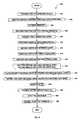
- FIG. 4is a flowchart illustrating a process for constructing a write element embodying the present invention.
- FIG. 5is a view taken from line 5 — 5 of FIG. 3 .
- the present inventionis embodied in a merged read/write head 66 including a read element 68 and an integral write element 70 , both of which are built upon a substrate 72 .
- the read element 68having been described with reference to the background of the invention, the present description will focus on the write element 70 , which embodies the subject matter of the present invention.
- the write element 70includes first and second poles 74 , 76 , which together join to form a magnetic yoke 78 .
- the poles 74 , 76join at one end to form a back-gap 80 , and are separated from one another everywhere else. Opposite the back-gap, each pole 74 , 76 terminates in a pole tip 82 , 84 . Opposite the back gap 80 , the poles 74 , 76 are separated by a write gap 88 .
- a layer of dielectric write gap material 89fills the write gap and extends beyond the write gap into the interior of the yoke 78 .
- An electrically conductive coil 90passes through the yoke 78 sitting atop the write gap material layer 89 .
- the first pole 74is constructed of a magnetic material having soft magnetic properties (i.e. low magnetostriction), preferably permalloy. Such soft magnetic properties are necessary to avoid domain boundary movement and associated popcorn noise in the read element 68 .
- the first pole 74includes a pedestal 92 , disposed opposite the back-gap 80 .
- the pedestalis constructed of a high magnetic moment material and functions to concentrate magnetic flux. While plated high magnetic moment materials do not generally exhibit soft magnetic properties, the pedestal is located far enough away from the read element 68 and is sufficiently small in size as compared with the rest of the first pole 74 so as to not generate undesirable popcorn noise.
- the pedestalis preferably constructed of FeXN nanocrystalline films with lamination layers of CoZrCr, which has been found to exhibit excellent magnetic properties including high magnetic moment and relatively low magnetostriction.
- the FeXN and the lamination layersare preferably sputter deposited onto a flat wafer that has been planarized using by chemical mechanical polishing (CMP).
- a first insulation layer 94covers the first pole, having a smooth flat upper surface that is flush with the smooth flat upper surface of the pedestal 92 . While this first insulation layer can be of many suitable materials having a high electrical resistance it is preferably constructed of Al 2 O 3 .
- the write gap material layer 89sits atop the smooth coplanar surfaces of the first insulation layer 94 and the pedestal 92 .
- the write gap material layeris preferably constructed of Al 2 O 3 or alternativetively of SiO 2 .
- the coil 90sits atop the write gap material layer 89 and is also covered by a second insulation layer 96 , which insulates the coil 90 from the second pole 76 as well as insulating the winds of the coil 90 from one another.
- the second insulation layerhas smoothly rounded edges formed by a curing process that will be described in greater detail below.
- the second pole 76includes a high magnetic moment layer 98 .
- the remainder of the second pole 76consists of a secondary layer 100 , constructed of a magnetic material such as plated Ni—Fe alloy, which can be readily electroplated and which exhibits good corrosion resistance.
- the high magnetic moment material layer 98which is preferably constructed of laminated FeXN nanocrystalline films with lamination layers of Co 90 Zr 9 Cr, improves performance of the head by facilitating magnetic flux flow through the second pole 76 , thereby resulting in a stronger fringing field at the write gap.
- the secondary layer 100which preferably makes up the bulk of the second pole 76 , provides a mask for etching the high magnetic moment material layer 98 as will be described in greater detail below.
- the edge of the coil insulation layer 96be placed further from the ABS than the pedestal edge, in which case the zero throat is defined by the pedestal.
- Apex reflectionis a major source of trackwidth variation during the fabrication of the top pole.
- the high magnetic moment layer 98is preferably on the order of 1 to a few times the thickness of the write gap 88 . In one embodiment the high magnetic moment layer 98 is roughly 0.5 um thick while the remainder of the second pole 76 is roughly 2 um thick and the pedestal is roughly 1 um thick
- the throat heightis preferably 3-10 times the thickness of the write gap 88 .
- the second poleincludes a layer of laminated high magnetic moment material as discussed above, but the first pole includes no pedestal.
- the first poleincludes a pedestal constructed of laminated high magnetic moment material, but the second pole does not include a laminated high magnetic moment layer.
- Such a constructioncould be useful where magnetic flux saturation is a problem. For example, if saturation were experienced in the pedestal of the first pole, then removing the high magnetic moment material from the second pole would decrease flux flow through the second pole, thereby preventing saturation at the pedestal. Similarly, when saturation is experienced in the second pole, the design having a high magnetic moment layer in the second pole and no pedestal on the first pole would promote flux flow through the second pole while limiting flux flow through the first pole, thereby preventing saturation in the second pole.
- the high magnetic moment layer 98 of the second pole 76can be constructed of laminated FeXN nanocrystalline films with lamination layers of cobalt based amorphous ferromagnetic alloy or alternatively of a non-magnetic dielectric material, while the pedestal is constructed of some other material such as a Ni—Fe alloy that can be electroplated.
- the pedestalcan be constructed of FeXN nanocrystalline films with lamination layers of a cobalt based amorphous ferromagnetic alloy or of a non-magnetic dielectric material, while the high magnetic moment layer of the second pole is some other plated high magnetic moment material such as NiFe55.
- a process 400is provided for constructing a write element of the present invention.
- the processbegins with a step 402 of constructing the first pole 74 .
- the first poleis preferably constructed by patterning and electroplating permalloy according to lithographic techniques familiar to those skilled in the art, and then is planarized by a chemical mechanical polishing process.
- a layer of high magnetic moment (high B sat ) materialis sputter deposited onto the first pole. This sputtering process results in a layer of high B sat material that completely covers the first pole as well as surrounding structure.
- the pedestalis patterned.
- a layer of photoresistis deposited so as to form a mask covering the area where the pedestal is to be formed. Then, in step 408 , ion milling is performed to the sputtered high B sat material not covered by the photoresist mask, thus forming the pedestal 92 .
- the ion milling stepleaves a tail of sputtered material tapering from the edge of the pedestal 92 .
- a first insulation layer 94is deposited onto the first pole.
- This first insulation layer 94is preferably constructed of Al 2 O 3 and is deposited sufficiently thick to at least reach the thickness of the pedestal 92 and is preferably slightly thicker than the pedestal 92 .
- a chemical mechanical polishing stepis performed to planarize the first insulation layer 94 , generating a flat planar surface across the first insulation layer 94 and the top of the pedestal 92 .
- the write gap material layer 89is deposited onto the smooth planar surface of the first insulation layer 94 and the pedestal 92 .
- the write gap material layercan be constructed of many suitable dielectric substances, but is preferably constructed of Al 2 O 3 or alternatively of SiO 2 .
- the electrically conductive coil 90is formed.
- the coilis preferably constructed of copper and is formed by methods that are familiar to those skilled in the art. These methods involve first depositing a seed layer of copper or some other suitable conductive material. The coil is then patterned and electroplated, and the seed layer removed by an etching process. With the coil thus formed, in a step 418 the second insulation layer 96 is formed.
- the second insulation layeris preferably constructed of a photoresist, which is spun onto the write gap material 89 and the coil 90 . The photoresist is patterned and exposed so that selective portions of the photoresist can be removed to provide vias for the back gap and the coil leads.
- the photoresistis cured by exposure to high temperatures, hardening the photoresist and providing it with smoothly rounded edges.
- a thin layer of dielectric materialcan be added to the top of the photoresist material.
- a thin layer of high B, materialis sputter deposited onto the structure.
- sputter depositionwill cover the entire exposed structure, including the second insulation layer 96 and the write gap material layer 89 .
- the high B sat materialis preferably constructed of FeRhN nanocrystalline films with lamination layers of CoZrCr, however other high B sat materials can also be used.
- the remainder of the second pole 76is deposited. This step involves forming a mask and then electroplating the second pole.
- the electroplated portion of the second pole 76can be formed with the desired shape.
- the electroplated portion of the first poleis preferably constructed of a NiFe alloy suitable for electroplating.
- an etching processis conducted to remove the high By material that is not covered by the plated portion of the second pole 76 .
- the resulting pole structureincludes a tail (not shown) of high B sat material that extends outward slightly from the edge of the pole 76 , beyond the edge of the plated portion.
- the ion milling stepleaves some of the sputtered material re deposited on the sidewalls of the second pole 76 .
- a step 426the pole tip of the second pole 76 is masked with photoresist. Then, in a step 428 the structure is again ion milled to remove material from the uncovered side portions or the tip of the second pole 76 . Thereafter, in a step 430 an etching process is performed to remove write gap material in the pole tip region at the sides of the second pole 76 . Then, with the write gap material locally removed, in a step 432 , yet another ion mill is performed to remove material from the corners of the pedestal 92 leaving notches 102 in the pedestal 92 , which can be more clearly seen with reference to FIG. 5, which shows an ABS view of the resulting pole trimmed pedestal. The notches 102 in the pedestal prevent magnetic flux from flowing through the sides of the yoke, thereby preventing side writing.
- the above processcan be slightly modified to construct one of the earlier described alternate embodiments of the invention.
- the write element 70could be constructed without the pedestal by patterning the first insulation layer to terminate short of the ABS plane 86 and eliminating the pedestal deposition process. In such a case the write gap material layer would simply slope down along the edge of the first insulation layer, and would sit atop the first pole 74 in the moon of the write gap.
- the write element 70could be constructed with a pedestal 92 as described above, but with a second pole formed without a laminated high B sat layer.
- high B sat layer of the second polecan be constructed of FeRhN nanocrystalline films with lamination layers of CoZrCr while the pedestal is constructed of some other magnetic material.
- the pedestalcan be constructed of FeRhN nanocrystalline films with lamination layers of CoZrCr while the high B sat layer of the second pole is construed of plated high B sat material such as NiFe55.
- the pedestalcan be constructed very thin with a tapered edge.
- Making the pedestal thinadvantageously simplifies the manufacturing process, and the tapered edge promotes flux flow into the pedestal, avoiding magnetic saturation in the pedestal.
- a method for constructing a write element having such pedestalis described in U.S. patent application Ser. No. 09/602,536, titled “INDUCTIVE WRITE HEAD INCORPORATING A THIN HIGH MOMENT PEDESTAL”, filed Jun. 3, 2000, the entirety of which is incorporated herein by reference.
Landscapes
- Engineering & Computer Science (AREA)
- Manufacturing & Machinery (AREA)
- Physics & Mathematics (AREA)
- Electromagnetism (AREA)
- Magnetic Heads (AREA)
Abstract
Description
Claims (18)
Priority Applications (2)
| Application Number | Priority Date | Filing Date | Title |
|---|---|---|---|
| US09/617,791US6618223B1 (en) | 2000-07-18 | 2000-07-18 | High speed, high areal density inductive writer |
| US10/656,311US7007372B1 (en) | 2000-07-18 | 2003-09-05 | Method for making high speed, high areal density inductive write structure |
Applications Claiming Priority (1)
| Application Number | Priority Date | Filing Date | Title |
|---|---|---|---|
| US09/617,791US6618223B1 (en) | 2000-07-18 | 2000-07-18 | High speed, high areal density inductive writer |
Related Child Applications (1)
| Application Number | Title | Priority Date | Filing Date |
|---|---|---|---|
| US10/656,311DivisionUS7007372B1 (en) | 2000-07-18 | 2003-09-05 | Method for making high speed, high areal density inductive write structure |
Publications (1)
| Publication Number | Publication Date |
|---|---|
| US6618223B1true US6618223B1 (en) | 2003-09-09 |
Family
ID=27789318
Family Applications (2)
| Application Number | Title | Priority Date | Filing Date |
|---|---|---|---|
| US09/617,791Expired - Fee RelatedUS6618223B1 (en) | 2000-07-18 | 2000-07-18 | High speed, high areal density inductive writer |
| US10/656,311Expired - Fee RelatedUS7007372B1 (en) | 2000-07-18 | 2003-09-05 | Method for making high speed, high areal density inductive write structure |
Family Applications After (1)
| Application Number | Title | Priority Date | Filing Date |
|---|---|---|---|
| US10/656,311Expired - Fee RelatedUS7007372B1 (en) | 2000-07-18 | 2003-09-05 | Method for making high speed, high areal density inductive write structure |
Country Status (1)
| Country | Link |
|---|---|
| US (2) | US6618223B1 (en) |
Cited By (139)
| Publication number | Priority date | Publication date | Assignee | Title |
|---|---|---|---|---|
| US20030179498A1 (en)* | 2002-03-22 | 2003-09-25 | Hsiao Wen-Chein David | Magnetic head having a notched pole piece structure and method of making the same |
| US20030202278A1 (en)* | 2002-04-29 | 2003-10-30 | Yingjian Chen | Inductive write head structure incorporating a high moment film in conjunction with at least one pole for use with magnetic storage media and a process for producing the same |
| US20050286170A1 (en)* | 2004-06-23 | 2005-12-29 | Tdk Corporation | Magnetic head for perpendicular magnetic recording |
| US20070019326A1 (en)* | 2005-07-20 | 2007-01-25 | Hitachi Global Storage Technologies Netherlands B.V. | Thin film magnetic head for high density recording |
| US7493688B1 (en)* | 2006-02-13 | 2009-02-24 | Western Digital (Fremont), Llc | Method of manufacturing a magnetic recording transducer |
| US20100250559A1 (en)* | 2004-05-28 | 2010-09-30 | Sap Aktiengesellschaft | Automatic Match Tuning |
| US20110013317A1 (en)* | 2009-07-16 | 2011-01-20 | Western Digital (Fremont), Llc | Method and system for fabricating magnetic transducers with improved pinning |
| US8227023B1 (en) | 2009-05-27 | 2012-07-24 | Western Digital (Fremont), Llc | Method and system for fabricating magnetic transducers with improved pinning |
| US8830628B1 (en) | 2009-02-23 | 2014-09-09 | Western Digital (Fremont), Llc | Method and system for providing a perpendicular magnetic recording head |
| US8879207B1 (en) | 2011-12-20 | 2014-11-04 | Western Digital (Fremont), Llc | Method for providing a side shield for a magnetic recording transducer using an air bridge |
| US8883017B1 (en) | 2013-03-12 | 2014-11-11 | Western Digital (Fremont), Llc | Method and system for providing a read transducer having seamless interfaces |
| US8917581B1 (en) | 2013-12-18 | 2014-12-23 | Western Digital Technologies, Inc. | Self-anneal process for a near field transducer and chimney in a hard disk drive assembly |
| US8923102B1 (en) | 2013-07-16 | 2014-12-30 | Western Digital (Fremont), Llc | Optical grating coupling for interferometric waveguides in heat assisted magnetic recording heads |
| US8947985B1 (en) | 2013-07-16 | 2015-02-03 | Western Digital (Fremont), Llc | Heat assisted magnetic recording transducers having a recessed pole |
| US8953422B1 (en) | 2014-06-10 | 2015-02-10 | Western Digital (Fremont), Llc | Near field transducer using dielectric waveguide core with fine ridge feature |
| US8958272B1 (en) | 2014-06-10 | 2015-02-17 | Western Digital (Fremont), Llc | Interfering near field transducer for energy assisted magnetic recording |
| US8971160B1 (en) | 2013-12-19 | 2015-03-03 | Western Digital (Fremont), Llc | Near field transducer with high refractive index pin for heat assisted magnetic recording |
| US8970988B1 (en) | 2013-12-31 | 2015-03-03 | Western Digital (Fremont), Llc | Electric gaps and method for making electric gaps for multiple sensor arrays |
| US8976635B1 (en) | 2014-06-10 | 2015-03-10 | Western Digital (Fremont), Llc | Near field transducer driven by a transverse electric waveguide for energy assisted magnetic recording |
| US8980109B1 (en) | 2012-12-11 | 2015-03-17 | Western Digital (Fremont), Llc | Method for providing a magnetic recording transducer using a combined main pole and side shield CMP for a wraparound shield scheme |
| US8982508B1 (en) | 2011-10-31 | 2015-03-17 | Western Digital (Fremont), Llc | Method for providing a side shield for a magnetic recording transducer |
| US8988812B1 (en) | 2013-11-27 | 2015-03-24 | Western Digital (Fremont), Llc | Multi-sensor array configuration for a two-dimensional magnetic recording (TDMR) operation |
| US8988825B1 (en) | 2014-02-28 | 2015-03-24 | Western Digital (Fremont, LLC | Method for fabricating a magnetic writer having half-side shields |
| US8984740B1 (en) | 2012-11-30 | 2015-03-24 | Western Digital (Fremont), Llc | Process for providing a magnetic recording transducer having a smooth magnetic seed layer |
| US8993217B1 (en) | 2013-04-04 | 2015-03-31 | Western Digital (Fremont), Llc | Double exposure technique for high resolution disk imaging |
| US8995087B1 (en) | 2006-11-29 | 2015-03-31 | Western Digital (Fremont), Llc | Perpendicular magnetic recording write head having a wrap around shield |
| US8997832B1 (en) | 2010-11-23 | 2015-04-07 | Western Digital (Fremont), Llc | Method of fabricating micrometer scale components |
| US9001467B1 (en) | 2014-03-05 | 2015-04-07 | Western Digital (Fremont), Llc | Method for fabricating side shields in a magnetic writer |
| US9001628B1 (en) | 2013-12-16 | 2015-04-07 | Western Digital (Fremont), Llc | Assistant waveguides for evaluating main waveguide coupling efficiency and diode laser alignment tolerances for hard disk |
| US9007719B1 (en) | 2013-10-23 | 2015-04-14 | Western Digital (Fremont), Llc | Systems and methods for using double mask techniques to achieve very small features |
| US9007879B1 (en) | 2014-06-10 | 2015-04-14 | Western Digital (Fremont), Llc | Interfering near field transducer having a wide metal bar feature for energy assisted magnetic recording |
| US9007725B1 (en) | 2014-10-07 | 2015-04-14 | Western Digital (Fremont), Llc | Sensor with positive coupling between dual ferromagnetic free layer laminates |
| US9013836B1 (en) | 2013-04-02 | 2015-04-21 | Western Digital (Fremont), Llc | Method and system for providing an antiferromagnetically coupled return pole |
| US9042057B1 (en) | 2013-01-09 | 2015-05-26 | Western Digital (Fremont), Llc | Methods for providing magnetic storage elements with high magneto-resistance using Heusler alloys |
| US9042208B1 (en) | 2013-03-11 | 2015-05-26 | Western Digital Technologies, Inc. | Disk drive measuring fly height by applying a bias voltage to an electrically insulated write component of a head |
| US9042051B2 (en) | 2013-08-15 | 2015-05-26 | Western Digital (Fremont), Llc | Gradient write gap for perpendicular magnetic recording writer |
| US9042058B1 (en) | 2013-10-17 | 2015-05-26 | Western Digital Technologies, Inc. | Shield designed for middle shields in a multiple sensor array |
| US9042052B1 (en) | 2014-06-23 | 2015-05-26 | Western Digital (Fremont), Llc | Magnetic writer having a partially shunted coil |
| US9053735B1 (en) | 2014-06-20 | 2015-06-09 | Western Digital (Fremont), Llc | Method for fabricating a magnetic writer using a full-film metal planarization |
| US9064507B1 (en) | 2009-07-31 | 2015-06-23 | Western Digital (Fremont), Llc | Magnetic etch-stop layer for magnetoresistive read heads |
| US9064527B1 (en) | 2013-04-12 | 2015-06-23 | Western Digital (Fremont), Llc | High order tapered waveguide for use in a heat assisted magnetic recording head |
| US9065043B1 (en) | 2012-06-29 | 2015-06-23 | Western Digital (Fremont), Llc | Tunnel magnetoresistance read head with narrow shield-to-shield spacing |
| US9064528B1 (en) | 2013-05-17 | 2015-06-23 | Western Digital Technologies, Inc. | Interferometric waveguide usable in shingled heat assisted magnetic recording in the absence of a near-field transducer |
| US9070381B1 (en) | 2013-04-12 | 2015-06-30 | Western Digital (Fremont), Llc | Magnetic recording read transducer having a laminated free layer |
| US9082423B1 (en) | 2013-12-18 | 2015-07-14 | Western Digital (Fremont), Llc | Magnetic recording write transducer having an improved trailing surface profile |
| US9087527B1 (en) | 2014-10-28 | 2015-07-21 | Western Digital (Fremont), Llc | Apparatus and method for middle shield connection in magnetic recording transducers |
| US9087534B1 (en) | 2011-12-20 | 2015-07-21 | Western Digital (Fremont), Llc | Method and system for providing a read transducer having soft and hard magnetic bias structures |
| US9093639B2 (en) | 2012-02-21 | 2015-07-28 | Western Digital (Fremont), Llc | Methods for manufacturing a magnetoresistive structure utilizing heating and cooling |
| US9104107B1 (en) | 2013-04-03 | 2015-08-11 | Western Digital (Fremont), Llc | DUV photoresist process |
| US9111550B1 (en) | 2014-12-04 | 2015-08-18 | Western Digital (Fremont), Llc | Write transducer having a magnetic buffer layer spaced between a side shield and a write pole by non-magnetic layers |
| US9111564B1 (en) | 2013-04-02 | 2015-08-18 | Western Digital (Fremont), Llc | Magnetic recording writer having a main pole with multiple flare angles |
| US9111558B1 (en) | 2014-03-14 | 2015-08-18 | Western Digital (Fremont), Llc | System and method of diffractive focusing of light in a waveguide |
| US9123362B1 (en) | 2011-03-22 | 2015-09-01 | Western Digital (Fremont), Llc | Methods for assembling an electrically assisted magnetic recording (EAMR) head |
| US9123358B1 (en) | 2012-06-11 | 2015-09-01 | Western Digital (Fremont), Llc | Conformal high moment side shield seed layer for perpendicular magnetic recording writer |
| US9123374B1 (en) | 2015-02-12 | 2015-09-01 | Western Digital (Fremont), Llc | Heat assisted magnetic recording writer having an integrated polarization rotation plate |
| US9123359B1 (en) | 2010-12-22 | 2015-09-01 | Western Digital (Fremont), Llc | Magnetic recording transducer with sputtered antiferromagnetic coupling trilayer between plated ferromagnetic shields and method of fabrication |
| US9135930B1 (en) | 2014-03-06 | 2015-09-15 | Western Digital (Fremont), Llc | Method for fabricating a magnetic write pole using vacuum deposition |
| US9135937B1 (en) | 2014-05-09 | 2015-09-15 | Western Digital (Fremont), Llc | Current modulation on laser diode for energy assisted magnetic recording transducer |
| US9142233B1 (en) | 2014-02-28 | 2015-09-22 | Western Digital (Fremont), Llc | Heat assisted magnetic recording writer having a recessed pole |
| US9147404B1 (en) | 2015-03-31 | 2015-09-29 | Western Digital (Fremont), Llc | Method and system for providing a read transducer having a dual free layer |
| US9147408B1 (en) | 2013-12-19 | 2015-09-29 | Western Digital (Fremont), Llc | Heated AFM layer deposition and cooling process for TMR magnetic recording sensor with high pinning field |
| US9153255B1 (en) | 2014-03-05 | 2015-10-06 | Western Digital (Fremont), Llc | Method for fabricating a magnetic writer having an asymmetric gap and shields |
| US9183854B2 (en) | 2014-02-24 | 2015-11-10 | Western Digital (Fremont), Llc | Method to make interferometric taper waveguide for HAMR light delivery |
| US9190085B1 (en) | 2014-03-12 | 2015-11-17 | Western Digital (Fremont), Llc | Waveguide with reflective grating for localized energy intensity |
| US9190079B1 (en) | 2014-09-22 | 2015-11-17 | Western Digital (Fremont), Llc | Magnetic write pole having engineered radius of curvature and chisel angle profiles |
| US9194692B1 (en) | 2013-12-06 | 2015-11-24 | Western Digital (Fremont), Llc | Systems and methods for using white light interferometry to measure undercut of a bi-layer structure |
| US9202493B1 (en) | 2014-02-28 | 2015-12-01 | Western Digital (Fremont), Llc | Method of making an ultra-sharp tip mode converter for a HAMR head |
| US9202480B2 (en) | 2009-10-14 | 2015-12-01 | Western Digital (Fremont), LLC. | Double patterning hard mask for damascene perpendicular magnetic recording (PMR) writer |
| US9214169B1 (en) | 2014-06-20 | 2015-12-15 | Western Digital (Fremont), Llc | Magnetic recording read transducer having a laminated free layer |
| US9213322B1 (en) | 2012-08-16 | 2015-12-15 | Western Digital (Fremont), Llc | Methods for providing run to run process control using a dynamic tuner |
| US9214172B2 (en) | 2013-10-23 | 2015-12-15 | Western Digital (Fremont), Llc | Method of manufacturing a magnetic read head |
| US9214165B1 (en) | 2014-12-18 | 2015-12-15 | Western Digital (Fremont), Llc | Magnetic writer having a gradient in saturation magnetization of the shields |
| US9230565B1 (en) | 2014-06-24 | 2016-01-05 | Western Digital (Fremont), Llc | Magnetic shield for magnetic recording head |
| US9236560B1 (en) | 2014-12-08 | 2016-01-12 | Western Digital (Fremont), Llc | Spin transfer torque tunneling magnetoresistive device having a laminated free layer with perpendicular magnetic anisotropy |
| US9245543B1 (en) | 2010-06-25 | 2016-01-26 | Western Digital (Fremont), Llc | Method for providing an energy assisted magnetic recording head having a laser integrally mounted to the slider |
| US9245562B1 (en) | 2015-03-30 | 2016-01-26 | Western Digital (Fremont), Llc | Magnetic recording writer with a composite main pole |
| US9245545B1 (en) | 2013-04-12 | 2016-01-26 | Wester Digital (Fremont), Llc | Short yoke length coils for magnetic heads in disk drives |
| US9251813B1 (en) | 2009-04-19 | 2016-02-02 | Western Digital (Fremont), Llc | Method of making a magnetic recording head |
| US9263071B1 (en) | 2015-03-31 | 2016-02-16 | Western Digital (Fremont), Llc | Flat NFT for heat assisted magnetic recording |
| US9263067B1 (en) | 2013-05-29 | 2016-02-16 | Western Digital (Fremont), Llc | Process for making PMR writer with constant side wall angle |
| US9269382B1 (en) | 2012-06-29 | 2016-02-23 | Western Digital (Fremont), Llc | Method and system for providing a read transducer having improved pinning of the pinned layer at higher recording densities |
| US9275657B1 (en) | 2013-08-14 | 2016-03-01 | Western Digital (Fremont), Llc | Process for making PMR writer with non-conformal side gaps |
| US9280990B1 (en) | 2013-12-11 | 2016-03-08 | Western Digital (Fremont), Llc | Method for fabricating a magnetic writer using multiple etches |
| US9287494B1 (en) | 2013-06-28 | 2016-03-15 | Western Digital (Fremont), Llc | Magnetic tunnel junction (MTJ) with a magnesium oxide tunnel barrier |
| US9286919B1 (en) | 2014-12-17 | 2016-03-15 | Western Digital (Fremont), Llc | Magnetic writer having a dual side gap |
| US9305583B1 (en) | 2014-02-18 | 2016-04-05 | Western Digital (Fremont), Llc | Method for fabricating a magnetic writer using multiple etches of damascene materials |
| US9312064B1 (en) | 2015-03-02 | 2016-04-12 | Western Digital (Fremont), Llc | Method to fabricate a magnetic head including ion milling of read gap using dual layer hard mask |
| US9318130B1 (en) | 2013-07-02 | 2016-04-19 | Western Digital (Fremont), Llc | Method to fabricate tunneling magnetic recording heads with extended pinned layer |
| US9336814B1 (en) | 2013-03-12 | 2016-05-10 | Western Digital (Fremont), Llc | Inverse tapered waveguide for use in a heat assisted magnetic recording head |
| US9343086B1 (en) | 2013-09-11 | 2016-05-17 | Western Digital (Fremont), Llc | Magnetic recording write transducer having an improved sidewall angle profile |
| US9343087B1 (en) | 2014-12-21 | 2016-05-17 | Western Digital (Fremont), Llc | Method for fabricating a magnetic writer having half shields |
| US9343098B1 (en) | 2013-08-23 | 2016-05-17 | Western Digital (Fremont), Llc | Method for providing a heat assisted magnetic recording transducer having protective pads |
| US9349394B1 (en) | 2013-10-18 | 2016-05-24 | Western Digital (Fremont), Llc | Method for fabricating a magnetic writer having a gradient side gap |
| US9349392B1 (en) | 2012-05-24 | 2016-05-24 | Western Digital (Fremont), Llc | Methods for improving adhesion on dielectric substrates |
| US9361913B1 (en) | 2013-06-03 | 2016-06-07 | Western Digital (Fremont), Llc | Recording read heads with a multi-layer AFM layer methods and apparatuses |
| US9361914B1 (en) | 2014-06-18 | 2016-06-07 | Western Digital (Fremont), Llc | Magnetic sensor with thin capping layer |
| US9368134B1 (en) | 2010-12-16 | 2016-06-14 | Western Digital (Fremont), Llc | Method and system for providing an antiferromagnetically coupled writer |
| US9384765B1 (en) | 2015-09-24 | 2016-07-05 | Western Digital (Fremont), Llc | Method and system for providing a HAMR writer having improved optical efficiency |
| US9384763B1 (en) | 2015-03-26 | 2016-07-05 | Western Digital (Fremont), Llc | Dual free layer magnetic reader having a rear bias structure including a soft bias layer |
| US9396742B1 (en) | 2012-11-30 | 2016-07-19 | Western Digital (Fremont), Llc | Magnetoresistive sensor for a magnetic storage system read head, and fabrication method thereof |
| US9396743B1 (en) | 2014-02-28 | 2016-07-19 | Western Digital (Fremont), Llc | Systems and methods for controlling soft bias thickness for tunnel magnetoresistance readers |
| US9406331B1 (en) | 2013-06-17 | 2016-08-02 | Western Digital (Fremont), Llc | Method for making ultra-narrow read sensor and read transducer device resulting therefrom |
| US9424866B1 (en) | 2015-09-24 | 2016-08-23 | Western Digital (Fremont), Llc | Heat assisted magnetic recording write apparatus having a dielectric gap |
| US9431038B1 (en) | 2015-06-29 | 2016-08-30 | Western Digital (Fremont), Llc | Method for fabricating a magnetic write pole having an improved sidewall angle profile |
| US9431032B1 (en) | 2013-08-14 | 2016-08-30 | Western Digital (Fremont), Llc | Electrical connection arrangement for a multiple sensor array usable in two-dimensional magnetic recording |
| US9431039B1 (en) | 2013-05-21 | 2016-08-30 | Western Digital (Fremont), Llc | Multiple sensor array usable in two-dimensional magnetic recording |
| US9431047B1 (en) | 2013-05-01 | 2016-08-30 | Western Digital (Fremont), Llc | Method for providing an improved AFM reader shield |
| US9431031B1 (en) | 2015-03-24 | 2016-08-30 | Western Digital (Fremont), Llc | System and method for magnetic transducers having multiple sensors and AFC shields |
| US9437251B1 (en) | 2014-12-22 | 2016-09-06 | Western Digital (Fremont), Llc | Apparatus and method having TDMR reader to reader shunts |
| US9443541B1 (en) | 2015-03-24 | 2016-09-13 | Western Digital (Fremont), Llc | Magnetic writer having a gradient in saturation magnetization of the shields and return pole |
| US9441938B1 (en) | 2013-10-08 | 2016-09-13 | Western Digital (Fremont), Llc | Test structures for measuring near field transducer disc length |
| US9449621B1 (en) | 2015-03-26 | 2016-09-20 | Western Digital (Fremont), Llc | Dual free layer magnetic reader having a rear bias structure having a high aspect ratio |
| US9449625B1 (en) | 2014-12-24 | 2016-09-20 | Western Digital (Fremont), Llc | Heat assisted magnetic recording head having a plurality of diffusion barrier layers |
| US9472216B1 (en) | 2015-09-23 | 2016-10-18 | Western Digital (Fremont), Llc | Differential dual free layer magnetic reader |
| US9484051B1 (en) | 2015-11-09 | 2016-11-01 | The Provost, Fellows, Foundation Scholars and the other members of Board, of the College of the Holy and Undivided Trinity of Queen Elizabeth near Dublin | Method and system for reducing undesirable reflections in a HAMR write apparatus |
| US9508363B1 (en) | 2014-06-17 | 2016-11-29 | Western Digital (Fremont), Llc | Method for fabricating a magnetic write pole having a leading edge bevel |
| US9508365B1 (en) | 2015-06-24 | 2016-11-29 | Western Digital (Fremont), LLC. | Magnetic reader having a crystal decoupling structure |
| US9508372B1 (en) | 2015-06-03 | 2016-11-29 | Western Digital (Fremont), Llc | Shingle magnetic writer having a low sidewall angle pole |
| US9530443B1 (en) | 2015-06-25 | 2016-12-27 | Western Digital (Fremont), Llc | Method for fabricating a magnetic recording device having a high aspect ratio structure |
| US9564150B1 (en) | 2015-11-24 | 2017-02-07 | Western Digital (Fremont), Llc | Magnetic read apparatus having an improved read sensor isolation circuit |
| US9595273B1 (en) | 2015-09-30 | 2017-03-14 | Western Digital (Fremont), Llc | Shingle magnetic writer having nonconformal shields |
| US9646639B2 (en) | 2015-06-26 | 2017-05-09 | Western Digital (Fremont), Llc | Heat assisted magnetic recording writer having integrated polarization rotation waveguides |
| US9666214B1 (en) | 2015-09-23 | 2017-05-30 | Western Digital (Fremont), Llc | Free layer magnetic reader that may have a reduced shield-to-shield spacing |
| US9721595B1 (en) | 2014-12-04 | 2017-08-01 | Western Digital (Fremont), Llc | Method for providing a storage device |
| US9741366B1 (en) | 2014-12-18 | 2017-08-22 | Western Digital (Fremont), Llc | Method for fabricating a magnetic writer having a gradient in saturation magnetization of the shields |
| US9740805B1 (en) | 2015-12-01 | 2017-08-22 | Western Digital (Fremont), Llc | Method and system for detecting hotspots for photolithographically-defined devices |
| US9754611B1 (en) | 2015-11-30 | 2017-09-05 | Western Digital (Fremont), Llc | Magnetic recording write apparatus having a stepped conformal trailing shield |
| US9767831B1 (en) | 2015-12-01 | 2017-09-19 | Western Digital (Fremont), Llc | Magnetic writer having convex trailing surface pole and conformal write gap |
| US9786301B1 (en) | 2014-12-02 | 2017-10-10 | Western Digital (Fremont), Llc | Apparatuses and methods for providing thin shields in a multiple sensor array |
| US9799351B1 (en) | 2015-11-30 | 2017-10-24 | Western Digital (Fremont), Llc | Short yoke length writer having assist coils |
| US9812155B1 (en) | 2015-11-23 | 2017-11-07 | Western Digital (Fremont), Llc | Method and system for fabricating high junction angle read sensors |
| US9842615B1 (en) | 2015-06-26 | 2017-12-12 | Western Digital (Fremont), Llc | Magnetic reader having a nonmagnetic insertion layer for the pinning layer |
| US9858951B1 (en) | 2015-12-01 | 2018-01-02 | Western Digital (Fremont), Llc | Method for providing a multilayer AFM layer in a read sensor |
| US9881638B1 (en) | 2014-12-17 | 2018-01-30 | Western Digital (Fremont), Llc | Method for providing a near-field transducer (NFT) for a heat assisted magnetic recording (HAMR) device |
| US9934811B1 (en) | 2014-03-07 | 2018-04-03 | Western Digital (Fremont), Llc | Methods for controlling stray fields of magnetic features using magneto-elastic anisotropy |
| US9953670B1 (en) | 2015-11-10 | 2018-04-24 | Western Digital (Fremont), Llc | Method and system for providing a HAMR writer including a multi-mode interference device |
| US10037770B1 (en) | 2015-11-12 | 2018-07-31 | Western Digital (Fremont), Llc | Method for providing a magnetic recording write apparatus having a seamless pole |
| US10074387B1 (en) | 2014-12-21 | 2018-09-11 | Western Digital (Fremont), Llc | Method and system for providing a read transducer having symmetric antiferromagnetically coupled shields |
| US10482907B1 (en)* | 2018-09-27 | 2019-11-19 | Western Digital Technologies, Inc. | Methods of protecting write pole from corrosion in HAMR head |
Families Citing this family (2)
| Publication number | Priority date | Publication date | Assignee | Title |
|---|---|---|---|---|
| US7748439B2 (en)* | 2004-04-13 | 2010-07-06 | Headway Technologies, Inc. | Heat extractor for magnetic reader-writer |
| US7948714B2 (en)* | 2006-01-31 | 2011-05-24 | Seagate Technology Llc | Transducer including an element of a transducer and a sidewall in an electrically conductive magnetic layer |
Citations (1)
| Publication number | Priority date | Publication date | Assignee | Title |
|---|---|---|---|---|
| US6108167A (en)* | 1997-09-10 | 2000-08-22 | Kabushiki Kaisha Toshiba | Magnetic head |
Family Cites Families (7)
| Publication number | Priority date | Publication date | Assignee | Title |
|---|---|---|---|---|
| JP2797982B2 (en)* | 1994-10-12 | 1998-09-17 | 日本電気株式会社 | MR head and method of manufacturing the same |
| US5901431A (en)* | 1995-06-07 | 1999-05-11 | International Business Machines Corporation | Method of fabricating a thin film inductive head having a second pole piece having a mushroom yoke portion |
| US5843521A (en)* | 1997-07-21 | 1998-12-01 | Headway Technologies, Inc. | Photoresist frame plated magnetic transducer pole layer employing high magnetic permeability seed layer |
| US6198609B1 (en)* | 1998-11-09 | 2001-03-06 | Read-Rite Corporation | CPP Magnetoresistive device with reduced edge effect and method for making same |
| US6233116B1 (en)* | 1998-11-13 | 2001-05-15 | Read-Rite Corporation | Thin film write head with improved laminated flux carrying structure and method of fabrication |
| US6317290B1 (en)* | 1999-08-31 | 2001-11-13 | Read-Rite Corporation | Advance pole trim writer with moment P1 and low apex angle |
| US6430806B1 (en)* | 2000-06-23 | 2002-08-13 | Read-Rite Corporation | Method for manufacturing an inductive write element employing bi-layer photoresist to define a thin high moment pole pedestal |
- 2000
- 2000-07-18USUS09/617,791patent/US6618223B1/ennot_activeExpired - Fee Related
- 2003
- 2003-09-05USUS10/656,311patent/US7007372B1/ennot_activeExpired - Fee Related
Patent Citations (1)
| Publication number | Priority date | Publication date | Assignee | Title |
|---|---|---|---|---|
| US6108167A (en)* | 1997-09-10 | 2000-08-22 | Kabushiki Kaisha Toshiba | Magnetic head |
Cited By (163)
| Publication number | Priority date | Publication date | Assignee | Title |
|---|---|---|---|---|
| US6947255B2 (en)* | 2002-03-22 | 2005-09-20 | International Business Machines Corporation | Magnetic head having a notched pole piece structure and method of making the same |
| US7489474B2 (en)* | 2002-03-22 | 2009-02-10 | International Business Machines Corporation | Magnetic head having a notched pole piece structure |
| US20030179498A1 (en)* | 2002-03-22 | 2003-09-25 | Hsiao Wen-Chein David | Magnetic head having a notched pole piece structure and method of making the same |
| US20030202278A1 (en)* | 2002-04-29 | 2003-10-30 | Yingjian Chen | Inductive write head structure incorporating a high moment film in conjunction with at least one pole for use with magnetic storage media and a process for producing the same |
| US6873494B2 (en)* | 2002-04-29 | 2005-03-29 | Western Digital (Fremont), Inc. | Write head with high moment film layer having tapered portion extending beyond write gap layer |
| US8271503B2 (en) | 2004-05-28 | 2012-09-18 | Sap Aktiengesellschaft | Automatic match tuning |
| US20100250559A1 (en)* | 2004-05-28 | 2010-09-30 | Sap Aktiengesellschaft | Automatic Match Tuning |
| US20050286170A1 (en)* | 2004-06-23 | 2005-12-29 | Tdk Corporation | Magnetic head for perpendicular magnetic recording |
| US7312951B2 (en)* | 2004-06-23 | 2007-12-25 | Tdk Corporation | Magnetic head for perpendicular magnetic recording |
| US20070019326A1 (en)* | 2005-07-20 | 2007-01-25 | Hitachi Global Storage Technologies Netherlands B.V. | Thin film magnetic head for high density recording |
| US7821737B2 (en)* | 2005-07-20 | 2010-10-26 | Hitachi Global Storage Technologies Netherlands B.V. | Thin film magnetic head for high density recording and having a leading side magnetic pole piece of variable width at the media facing surface |
| US7493688B1 (en)* | 2006-02-13 | 2009-02-24 | Western Digital (Fremont), Llc | Method of manufacturing a magnetic recording transducer |
| US8995087B1 (en) | 2006-11-29 | 2015-03-31 | Western Digital (Fremont), Llc | Perpendicular magnetic recording write head having a wrap around shield |
| US8830628B1 (en) | 2009-02-23 | 2014-09-09 | Western Digital (Fremont), Llc | Method and system for providing a perpendicular magnetic recording head |
| US9251813B1 (en) | 2009-04-19 | 2016-02-02 | Western Digital (Fremont), Llc | Method of making a magnetic recording head |
| US8227023B1 (en) | 2009-05-27 | 2012-07-24 | Western Digital (Fremont), Llc | Method and system for fabricating magnetic transducers with improved pinning |
| US9007728B1 (en) | 2009-05-27 | 2015-04-14 | Western Digital (Fremont), Llc | Method and system for fabricating magnetic transducers with improved pinning |
| US8164864B2 (en) | 2009-07-16 | 2012-04-24 | Western Digital (Fremont), Llc | Method and system for fabricating magnetic transducers with improved pinning |
| US20110013317A1 (en)* | 2009-07-16 | 2011-01-20 | Western Digital (Fremont), Llc | Method and system for fabricating magnetic transducers with improved pinning |
| US9064507B1 (en) | 2009-07-31 | 2015-06-23 | Western Digital (Fremont), Llc | Magnetic etch-stop layer for magnetoresistive read heads |
| US9202480B2 (en) | 2009-10-14 | 2015-12-01 | Western Digital (Fremont), LLC. | Double patterning hard mask for damascene perpendicular magnetic recording (PMR) writer |
| US9245543B1 (en) | 2010-06-25 | 2016-01-26 | Western Digital (Fremont), Llc | Method for providing an energy assisted magnetic recording head having a laser integrally mounted to the slider |
| US9159345B1 (en) | 2010-11-23 | 2015-10-13 | Western Digital (Fremont), Llc | Micrometer scale components |
| US9672847B2 (en) | 2010-11-23 | 2017-06-06 | Western Digital (Fremont), Llc | Micrometer scale components |
| US8997832B1 (en) | 2010-11-23 | 2015-04-07 | Western Digital (Fremont), Llc | Method of fabricating micrometer scale components |
| US9368134B1 (en) | 2010-12-16 | 2016-06-14 | Western Digital (Fremont), Llc | Method and system for providing an antiferromagnetically coupled writer |
| US9123359B1 (en) | 2010-12-22 | 2015-09-01 | Western Digital (Fremont), Llc | Magnetic recording transducer with sputtered antiferromagnetic coupling trilayer between plated ferromagnetic shields and method of fabrication |
| US9123362B1 (en) | 2011-03-22 | 2015-09-01 | Western Digital (Fremont), Llc | Methods for assembling an electrically assisted magnetic recording (EAMR) head |
| US8982508B1 (en) | 2011-10-31 | 2015-03-17 | Western Digital (Fremont), Llc | Method for providing a side shield for a magnetic recording transducer |
| US9087534B1 (en) | 2011-12-20 | 2015-07-21 | Western Digital (Fremont), Llc | Method and system for providing a read transducer having soft and hard magnetic bias structures |
| US8879207B1 (en) | 2011-12-20 | 2014-11-04 | Western Digital (Fremont), Llc | Method for providing a side shield for a magnetic recording transducer using an air bridge |
| US9093639B2 (en) | 2012-02-21 | 2015-07-28 | Western Digital (Fremont), Llc | Methods for manufacturing a magnetoresistive structure utilizing heating and cooling |
| US9940950B2 (en) | 2012-05-24 | 2018-04-10 | Western Digital (Fremont), Llc | Methods for improving adhesion on dielectric substrates |
| US9349392B1 (en) | 2012-05-24 | 2016-05-24 | Western Digital (Fremont), Llc | Methods for improving adhesion on dielectric substrates |
| US9123358B1 (en) | 2012-06-11 | 2015-09-01 | Western Digital (Fremont), Llc | Conformal high moment side shield seed layer for perpendicular magnetic recording writer |
| US9065043B1 (en) | 2012-06-29 | 2015-06-23 | Western Digital (Fremont), Llc | Tunnel magnetoresistance read head with narrow shield-to-shield spacing |
| US9269382B1 (en) | 2012-06-29 | 2016-02-23 | Western Digital (Fremont), Llc | Method and system for providing a read transducer having improved pinning of the pinned layer at higher recording densities |
| US9412400B2 (en) | 2012-06-29 | 2016-08-09 | Western Digital (Fremont), Llc | Tunnel magnetoresistance read head with narrow shield-to-shield spacing |
| US9213322B1 (en) | 2012-08-16 | 2015-12-15 | Western Digital (Fremont), Llc | Methods for providing run to run process control using a dynamic tuner |
| US9396742B1 (en) | 2012-11-30 | 2016-07-19 | Western Digital (Fremont), Llc | Magnetoresistive sensor for a magnetic storage system read head, and fabrication method thereof |
| US8984740B1 (en) | 2012-11-30 | 2015-03-24 | Western Digital (Fremont), Llc | Process for providing a magnetic recording transducer having a smooth magnetic seed layer |
| US8980109B1 (en) | 2012-12-11 | 2015-03-17 | Western Digital (Fremont), Llc | Method for providing a magnetic recording transducer using a combined main pole and side shield CMP for a wraparound shield scheme |
| US9042057B1 (en) | 2013-01-09 | 2015-05-26 | Western Digital (Fremont), Llc | Methods for providing magnetic storage elements with high magneto-resistance using Heusler alloys |
| US9042208B1 (en) | 2013-03-11 | 2015-05-26 | Western Digital Technologies, Inc. | Disk drive measuring fly height by applying a bias voltage to an electrically insulated write component of a head |
| US9336814B1 (en) | 2013-03-12 | 2016-05-10 | Western Digital (Fremont), Llc | Inverse tapered waveguide for use in a heat assisted magnetic recording head |
| US8883017B1 (en) | 2013-03-12 | 2014-11-11 | Western Digital (Fremont), Llc | Method and system for providing a read transducer having seamless interfaces |
| US9111564B1 (en) | 2013-04-02 | 2015-08-18 | Western Digital (Fremont), Llc | Magnetic recording writer having a main pole with multiple flare angles |
| US9013836B1 (en) | 2013-04-02 | 2015-04-21 | Western Digital (Fremont), Llc | Method and system for providing an antiferromagnetically coupled return pole |
| US9104107B1 (en) | 2013-04-03 | 2015-08-11 | Western Digital (Fremont), Llc | DUV photoresist process |
| US8993217B1 (en) | 2013-04-04 | 2015-03-31 | Western Digital (Fremont), Llc | Double exposure technique for high resolution disk imaging |
| US9070381B1 (en) | 2013-04-12 | 2015-06-30 | Western Digital (Fremont), Llc | Magnetic recording read transducer having a laminated free layer |
| US9064527B1 (en) | 2013-04-12 | 2015-06-23 | Western Digital (Fremont), Llc | High order tapered waveguide for use in a heat assisted magnetic recording head |
| US9245545B1 (en) | 2013-04-12 | 2016-01-26 | Wester Digital (Fremont), Llc | Short yoke length coils for magnetic heads in disk drives |
| US9431047B1 (en) | 2013-05-01 | 2016-08-30 | Western Digital (Fremont), Llc | Method for providing an improved AFM reader shield |
| US9064528B1 (en) | 2013-05-17 | 2015-06-23 | Western Digital Technologies, Inc. | Interferometric waveguide usable in shingled heat assisted magnetic recording in the absence of a near-field transducer |
| US9431039B1 (en) | 2013-05-21 | 2016-08-30 | Western Digital (Fremont), Llc | Multiple sensor array usable in two-dimensional magnetic recording |
| US9263067B1 (en) | 2013-05-29 | 2016-02-16 | Western Digital (Fremont), Llc | Process for making PMR writer with constant side wall angle |
| US9361913B1 (en) | 2013-06-03 | 2016-06-07 | Western Digital (Fremont), Llc | Recording read heads with a multi-layer AFM layer methods and apparatuses |
| US9406331B1 (en) | 2013-06-17 | 2016-08-02 | Western Digital (Fremont), Llc | Method for making ultra-narrow read sensor and read transducer device resulting therefrom |
| US9287494B1 (en) | 2013-06-28 | 2016-03-15 | Western Digital (Fremont), Llc | Magnetic tunnel junction (MTJ) with a magnesium oxide tunnel barrier |
| US9318130B1 (en) | 2013-07-02 | 2016-04-19 | Western Digital (Fremont), Llc | Method to fabricate tunneling magnetic recording heads with extended pinned layer |
| US8923102B1 (en) | 2013-07-16 | 2014-12-30 | Western Digital (Fremont), Llc | Optical grating coupling for interferometric waveguides in heat assisted magnetic recording heads |
| US8947985B1 (en) | 2013-07-16 | 2015-02-03 | Western Digital (Fremont), Llc | Heat assisted magnetic recording transducers having a recessed pole |
| US9275657B1 (en) | 2013-08-14 | 2016-03-01 | Western Digital (Fremont), Llc | Process for making PMR writer with non-conformal side gaps |
| US9431032B1 (en) | 2013-08-14 | 2016-08-30 | Western Digital (Fremont), Llc | Electrical connection arrangement for a multiple sensor array usable in two-dimensional magnetic recording |
| US9042051B2 (en) | 2013-08-15 | 2015-05-26 | Western Digital (Fremont), Llc | Gradient write gap for perpendicular magnetic recording writer |
| US9343098B1 (en) | 2013-08-23 | 2016-05-17 | Western Digital (Fremont), Llc | Method for providing a heat assisted magnetic recording transducer having protective pads |
| US9343086B1 (en) | 2013-09-11 | 2016-05-17 | Western Digital (Fremont), Llc | Magnetic recording write transducer having an improved sidewall angle profile |
| US9441938B1 (en) | 2013-10-08 | 2016-09-13 | Western Digital (Fremont), Llc | Test structures for measuring near field transducer disc length |
| US9042058B1 (en) | 2013-10-17 | 2015-05-26 | Western Digital Technologies, Inc. | Shield designed for middle shields in a multiple sensor array |
| US9349394B1 (en) | 2013-10-18 | 2016-05-24 | Western Digital (Fremont), Llc | Method for fabricating a magnetic writer having a gradient side gap |
| US9214172B2 (en) | 2013-10-23 | 2015-12-15 | Western Digital (Fremont), Llc | Method of manufacturing a magnetic read head |
| US9830936B2 (en) | 2013-10-23 | 2017-11-28 | Western Digital (Fremont), Llc | Magnetic read head with antiferromagentic layer |
| US9007719B1 (en) | 2013-10-23 | 2015-04-14 | Western Digital (Fremont), Llc | Systems and methods for using double mask techniques to achieve very small features |
| US8988812B1 (en) | 2013-11-27 | 2015-03-24 | Western Digital (Fremont), Llc | Multi-sensor array configuration for a two-dimensional magnetic recording (TDMR) operation |
| US9194692B1 (en) | 2013-12-06 | 2015-11-24 | Western Digital (Fremont), Llc | Systems and methods for using white light interferometry to measure undercut of a bi-layer structure |
| US9280990B1 (en) | 2013-12-11 | 2016-03-08 | Western Digital (Fremont), Llc | Method for fabricating a magnetic writer using multiple etches |
| US9001628B1 (en) | 2013-12-16 | 2015-04-07 | Western Digital (Fremont), Llc | Assistant waveguides for evaluating main waveguide coupling efficiency and diode laser alignment tolerances for hard disk |
| US9082423B1 (en) | 2013-12-18 | 2015-07-14 | Western Digital (Fremont), Llc | Magnetic recording write transducer having an improved trailing surface profile |
| US8917581B1 (en) | 2013-12-18 | 2014-12-23 | Western Digital Technologies, Inc. | Self-anneal process for a near field transducer and chimney in a hard disk drive assembly |
| US9147408B1 (en) | 2013-12-19 | 2015-09-29 | Western Digital (Fremont), Llc | Heated AFM layer deposition and cooling process for TMR magnetic recording sensor with high pinning field |
| US8971160B1 (en) | 2013-12-19 | 2015-03-03 | Western Digital (Fremont), Llc | Near field transducer with high refractive index pin for heat assisted magnetic recording |
| US8970988B1 (en) | 2013-12-31 | 2015-03-03 | Western Digital (Fremont), Llc | Electric gaps and method for making electric gaps for multiple sensor arrays |
| US9305583B1 (en) | 2014-02-18 | 2016-04-05 | Western Digital (Fremont), Llc | Method for fabricating a magnetic writer using multiple etches of damascene materials |
| US9183854B2 (en) | 2014-02-24 | 2015-11-10 | Western Digital (Fremont), Llc | Method to make interferometric taper waveguide for HAMR light delivery |
| US8988825B1 (en) | 2014-02-28 | 2015-03-24 | Western Digital (Fremont, LLC | Method for fabricating a magnetic writer having half-side shields |
| US9396743B1 (en) | 2014-02-28 | 2016-07-19 | Western Digital (Fremont), Llc | Systems and methods for controlling soft bias thickness for tunnel magnetoresistance readers |
| US9202493B1 (en) | 2014-02-28 | 2015-12-01 | Western Digital (Fremont), Llc | Method of making an ultra-sharp tip mode converter for a HAMR head |
| US9142233B1 (en) | 2014-02-28 | 2015-09-22 | Western Digital (Fremont), Llc | Heat assisted magnetic recording writer having a recessed pole |
| US9349393B2 (en) | 2014-03-05 | 2016-05-24 | Western Digital (Fremont), Llc | Magnetic writer having an asymmetric gap and shields |
| US9001467B1 (en) | 2014-03-05 | 2015-04-07 | Western Digital (Fremont), Llc | Method for fabricating side shields in a magnetic writer |
| US9153255B1 (en) | 2014-03-05 | 2015-10-06 | Western Digital (Fremont), Llc | Method for fabricating a magnetic writer having an asymmetric gap and shields |
| US9135930B1 (en) | 2014-03-06 | 2015-09-15 | Western Digital (Fremont), Llc | Method for fabricating a magnetic write pole using vacuum deposition |
| US9934811B1 (en) | 2014-03-07 | 2018-04-03 | Western Digital (Fremont), Llc | Methods for controlling stray fields of magnetic features using magneto-elastic anisotropy |
| US9190085B1 (en) | 2014-03-12 | 2015-11-17 | Western Digital (Fremont), Llc | Waveguide with reflective grating for localized energy intensity |
| US9495984B2 (en) | 2014-03-12 | 2016-11-15 | Western Digital (Fremont), Llc | Waveguide with reflective grating for localized energy intensity |
| US9111558B1 (en) | 2014-03-14 | 2015-08-18 | Western Digital (Fremont), Llc | System and method of diffractive focusing of light in a waveguide |
| US9135937B1 (en) | 2014-05-09 | 2015-09-15 | Western Digital (Fremont), Llc | Current modulation on laser diode for energy assisted magnetic recording transducer |
| US8958272B1 (en) | 2014-06-10 | 2015-02-17 | Western Digital (Fremont), Llc | Interfering near field transducer for energy assisted magnetic recording |
| US8976635B1 (en) | 2014-06-10 | 2015-03-10 | Western Digital (Fremont), Llc | Near field transducer driven by a transverse electric waveguide for energy assisted magnetic recording |
| US9311952B2 (en) | 2014-06-10 | 2016-04-12 | Western Digital (Fremont), Llc | Interfering near field transducer for energy assisted magnetic recording |
| US9007879B1 (en) | 2014-06-10 | 2015-04-14 | Western Digital (Fremont), Llc | Interfering near field transducer having a wide metal bar feature for energy assisted magnetic recording |
| US9159346B1 (en) | 2014-06-10 | 2015-10-13 | Western Digital (Fremont), Llc | Near field transducer using dielectric waveguide core with fine ridge feature |
| US8953422B1 (en) | 2014-06-10 | 2015-02-10 | Western Digital (Fremont), Llc | Near field transducer using dielectric waveguide core with fine ridge feature |
| US9508363B1 (en) | 2014-06-17 | 2016-11-29 | Western Digital (Fremont), Llc | Method for fabricating a magnetic write pole having a leading edge bevel |
| US9361914B1 (en) | 2014-06-18 | 2016-06-07 | Western Digital (Fremont), Llc | Magnetic sensor with thin capping layer |
| US9053735B1 (en) | 2014-06-20 | 2015-06-09 | Western Digital (Fremont), Llc | Method for fabricating a magnetic writer using a full-film metal planarization |
| US9214169B1 (en) | 2014-06-20 | 2015-12-15 | Western Digital (Fremont), Llc | Magnetic recording read transducer having a laminated free layer |
| US9042052B1 (en) | 2014-06-23 | 2015-05-26 | Western Digital (Fremont), Llc | Magnetic writer having a partially shunted coil |
| US9230565B1 (en) | 2014-06-24 | 2016-01-05 | Western Digital (Fremont), Llc | Magnetic shield for magnetic recording head |
| US9190079B1 (en) | 2014-09-22 | 2015-11-17 | Western Digital (Fremont), Llc | Magnetic write pole having engineered radius of curvature and chisel angle profiles |
| US9007725B1 (en) | 2014-10-07 | 2015-04-14 | Western Digital (Fremont), Llc | Sensor with positive coupling between dual ferromagnetic free layer laminates |
| US9087527B1 (en) | 2014-10-28 | 2015-07-21 | Western Digital (Fremont), Llc | Apparatus and method for middle shield connection in magnetic recording transducers |
| US9786301B1 (en) | 2014-12-02 | 2017-10-10 | Western Digital (Fremont), Llc | Apparatuses and methods for providing thin shields in a multiple sensor array |
| US9721595B1 (en) | 2014-12-04 | 2017-08-01 | Western Digital (Fremont), Llc | Method for providing a storage device |
| US9111550B1 (en) | 2014-12-04 | 2015-08-18 | Western Digital (Fremont), Llc | Write transducer having a magnetic buffer layer spaced between a side shield and a write pole by non-magnetic layers |
| US9705072B2 (en) | 2014-12-08 | 2017-07-11 | Western Digital (Fremont), Llc | Spin transfer torque tunneling magnetoresistive device having a laminated free layer with perpendicular magnetic anisotropy |
| US9236560B1 (en) | 2014-12-08 | 2016-01-12 | Western Digital (Fremont), Llc | Spin transfer torque tunneling magnetoresistive device having a laminated free layer with perpendicular magnetic anisotropy |
| US9881638B1 (en) | 2014-12-17 | 2018-01-30 | Western Digital (Fremont), Llc | Method for providing a near-field transducer (NFT) for a heat assisted magnetic recording (HAMR) device |
| US10553241B2 (en) | 2014-12-17 | 2020-02-04 | Western Digital Technologies, Inc. | Near-field transducer (NFT) for a heat assisted magnetic recording (HAMR) device |
| US9286919B1 (en) | 2014-12-17 | 2016-03-15 | Western Digital (Fremont), Llc | Magnetic writer having a dual side gap |
| US9214165B1 (en) | 2014-12-18 | 2015-12-15 | Western Digital (Fremont), Llc | Magnetic writer having a gradient in saturation magnetization of the shields |
| US9741366B1 (en) | 2014-12-18 | 2017-08-22 | Western Digital (Fremont), Llc | Method for fabricating a magnetic writer having a gradient in saturation magnetization of the shields |
| US10074387B1 (en) | 2014-12-21 | 2018-09-11 | Western Digital (Fremont), Llc | Method and system for providing a read transducer having symmetric antiferromagnetically coupled shields |
| US9343087B1 (en) | 2014-12-21 | 2016-05-17 | Western Digital (Fremont), Llc | Method for fabricating a magnetic writer having half shields |
| US9437251B1 (en) | 2014-12-22 | 2016-09-06 | Western Digital (Fremont), Llc | Apparatus and method having TDMR reader to reader shunts |
| US9449625B1 (en) | 2014-12-24 | 2016-09-20 | Western Digital (Fremont), Llc | Heat assisted magnetic recording head having a plurality of diffusion barrier layers |
| US9123374B1 (en) | 2015-02-12 | 2015-09-01 | Western Digital (Fremont), Llc | Heat assisted magnetic recording writer having an integrated polarization rotation plate |
| US9312064B1 (en) | 2015-03-02 | 2016-04-12 | Western Digital (Fremont), Llc | Method to fabricate a magnetic head including ion milling of read gap using dual layer hard mask |
| US9431031B1 (en) | 2015-03-24 | 2016-08-30 | Western Digital (Fremont), Llc | System and method for magnetic transducers having multiple sensors and AFC shields |
| US9443541B1 (en) | 2015-03-24 | 2016-09-13 | Western Digital (Fremont), Llc | Magnetic writer having a gradient in saturation magnetization of the shields and return pole |
| US9922672B1 (en) | 2015-03-26 | 2018-03-20 | Western Digital (Fremont), Llc | Dual free layer magnetic reader having a rear bias structure having a high aspect ratio |
| US9449621B1 (en) | 2015-03-26 | 2016-09-20 | Western Digital (Fremont), Llc | Dual free layer magnetic reader having a rear bias structure having a high aspect ratio |
| US9384763B1 (en) | 2015-03-26 | 2016-07-05 | Western Digital (Fremont), Llc | Dual free layer magnetic reader having a rear bias structure including a soft bias layer |
| US9245562B1 (en) | 2015-03-30 | 2016-01-26 | Western Digital (Fremont), Llc | Magnetic recording writer with a composite main pole |
| US9263071B1 (en) | 2015-03-31 | 2016-02-16 | Western Digital (Fremont), Llc | Flat NFT for heat assisted magnetic recording |
| US9147404B1 (en) | 2015-03-31 | 2015-09-29 | Western Digital (Fremont), Llc | Method and system for providing a read transducer having a dual free layer |
| US9508372B1 (en) | 2015-06-03 | 2016-11-29 | Western Digital (Fremont), Llc | Shingle magnetic writer having a low sidewall angle pole |
| US9508365B1 (en) | 2015-06-24 | 2016-11-29 | Western Digital (Fremont), LLC. | Magnetic reader having a crystal decoupling structure |
| US9530443B1 (en) | 2015-06-25 | 2016-12-27 | Western Digital (Fremont), Llc | Method for fabricating a magnetic recording device having a high aspect ratio structure |
| US9646639B2 (en) | 2015-06-26 | 2017-05-09 | Western Digital (Fremont), Llc | Heat assisted magnetic recording writer having integrated polarization rotation waveguides |
| US10242700B2 (en) | 2015-06-26 | 2019-03-26 | Western Digital (Fremont), Llc | Magnetic reader having a nonmagnetic insertion layer for the pinning layer |
| US9842615B1 (en) | 2015-06-26 | 2017-12-12 | Western Digital (Fremont), Llc | Magnetic reader having a nonmagnetic insertion layer for the pinning layer |
| US9431038B1 (en) | 2015-06-29 | 2016-08-30 | Western Digital (Fremont), Llc | Method for fabricating a magnetic write pole having an improved sidewall angle profile |
| US9666214B1 (en) | 2015-09-23 | 2017-05-30 | Western Digital (Fremont), Llc | Free layer magnetic reader that may have a reduced shield-to-shield spacing |
| US9472216B1 (en) | 2015-09-23 | 2016-10-18 | Western Digital (Fremont), Llc | Differential dual free layer magnetic reader |
| US9424866B1 (en) | 2015-09-24 | 2016-08-23 | Western Digital (Fremont), Llc | Heat assisted magnetic recording write apparatus having a dielectric gap |
| US9384765B1 (en) | 2015-09-24 | 2016-07-05 | Western Digital (Fremont), Llc | Method and system for providing a HAMR writer having improved optical efficiency |
| US9595273B1 (en) | 2015-09-30 | 2017-03-14 | Western Digital (Fremont), Llc | Shingle magnetic writer having nonconformal shields |
| US9484051B1 (en) | 2015-11-09 | 2016-11-01 | The Provost, Fellows, Foundation Scholars and the other members of Board, of the College of the Holy and Undivided Trinity of Queen Elizabeth near Dublin | Method and system for reducing undesirable reflections in a HAMR write apparatus |
| US9953670B1 (en) | 2015-11-10 | 2018-04-24 | Western Digital (Fremont), Llc | Method and system for providing a HAMR writer including a multi-mode interference device |
| US10381029B2 (en) | 2015-11-10 | 2019-08-13 | Western Digital (Fremont), Llc | Method and system for providing a HAMR writer including a multi-mode interference device |
| US10037770B1 (en) | 2015-11-12 | 2018-07-31 | Western Digital (Fremont), Llc | Method for providing a magnetic recording write apparatus having a seamless pole |
| US9812155B1 (en) | 2015-11-23 | 2017-11-07 | Western Digital (Fremont), Llc | Method and system for fabricating high junction angle read sensors |
| US9564150B1 (en) | 2015-11-24 | 2017-02-07 | Western Digital (Fremont), Llc | Magnetic read apparatus having an improved read sensor isolation circuit |
| US9799351B1 (en) | 2015-11-30 | 2017-10-24 | Western Digital (Fremont), Llc | Short yoke length writer having assist coils |
| US9754611B1 (en) | 2015-11-30 | 2017-09-05 | Western Digital (Fremont), Llc | Magnetic recording write apparatus having a stepped conformal trailing shield |
| US10121495B2 (en) | 2015-11-30 | 2018-11-06 | Western Digital (Fremont), Llc | Magnetic recording write apparatus having a stepped conformal trailing shield |
| US9858951B1 (en) | 2015-12-01 | 2018-01-02 | Western Digital (Fremont), Llc | Method for providing a multilayer AFM layer in a read sensor |
| US9767831B1 (en) | 2015-12-01 | 2017-09-19 | Western Digital (Fremont), Llc | Magnetic writer having convex trailing surface pole and conformal write gap |
| US9997177B2 (en) | 2015-12-01 | 2018-06-12 | Western Digital (Fremont), Llc | Magnetic writer having convex trailing surface pole and conformal write gap |
| US9740805B1 (en) | 2015-12-01 | 2017-08-22 | Western Digital (Fremont), Llc | Method and system for detecting hotspots for photolithographically-defined devices |
| US10482907B1 (en)* | 2018-09-27 | 2019-11-19 | Western Digital Technologies, Inc. | Methods of protecting write pole from corrosion in HAMR head |
Also Published As
| Publication number | Publication date |
|---|---|
| US7007372B1 (en) | 2006-03-07 |
Similar Documents
| Publication | Publication Date | Title |
|---|---|---|
| US6618223B1 (en) | High speed, high areal density inductive writer | |
| US6430806B1 (en) | Method for manufacturing an inductive write element employing bi-layer photoresist to define a thin high moment pole pedestal | |
| US6190764B1 (en) | Inductive write head for magnetic data storage media | |
| US6433968B1 (en) | Merged read/write head and method of fabricating same | |
| US6530141B2 (en) | Method of forming thin film magnetic recording head with narrow track width performing high density recording at high driving frequency | |
| KR100319035B1 (en) | Thin film magnetic head and recording reproducing separate type magnetic head, and magnetic recording reproducing apparatus using them | |
| US6975486B2 (en) | Thin film write head having a laminated, flat top pole with bottom shaper and method of fabrication | |
| US6989962B1 (en) | Inductive write head having high magnetic moment poles and low magnetic moment thin layer in the back gap, and methods for making | |
| US6496335B2 (en) | Magnetic head shield structure having high magnetic stability | |
| US6922316B2 (en) | Thin-film magnetic head and method of manufacturing same | |
| US6317301B2 (en) | Magnetoresistive effect type reproducing head and magnetic disk apparatus equipped with the reproducing head | |
| JP2003157510A (en) | Thin-film writing head, data storage system and method for manufacturing the thin-film writing head | |
| KR20040023524A (en) | Current-perpendicular-to-the-plane struc ture magnetoresistive element | |
| JP2004342210A (en) | Magnetic head for perpendicular magnetic recording and its manufacturing method, head gimbal assembly, and hard disk drive | |
| CN100405464C (en) | Magnetic recording medium, method of manufacturing magnetic recording medium, and magnetic recording device | |
| US6687085B2 (en) | Perpendicular write head with high magnetization pole material and method of fabricating the write head | |
| JP2002329905A (en) | CPP structure magnetoresistive element and method of manufacturing the same | |
| JP4230702B2 (en) | CPP structure magnetoresistive element manufacturing method | |
| JPH10241125A (en) | Thin film magnetic head, read / write separated magnetic head, and magnetic storage / reproducing apparatus using the same | |
| JP3639529B2 (en) | Thin film magnetic head and method of manufacturing thin film magnetic head | |
| JP3640916B2 (en) | Thin film magnetic head and manufacturing method thereof | |
| JPH11213332A (en) | Thin-film magnetic head and magnetic disk drive | |
| JP2007184022A (en) | Manufacturing method of main magnetic pole of perpendicular magnetic recording head | |
| KR100331188B1 (en) | A thin film magnetic head, a recording/reproduction separation type head and a magnetic recording and reproducing apparatus using the head | |
| JPH117609A (en) | Thin-film magnetic head, recording / reproducing separated type head, and magnetic storage / reproducing apparatus using the same |
Legal Events
| Date | Code | Title | Description |
|---|---|---|---|
| AS | Assignment | Owner name:READ-RITE CORPORATION, CALIFORNIA Free format text:ASSIGNMENT OF ASSIGNORS INTEREST;ASSIGNORS:CHEN, YINGJIAN;TONG, HUA-CHING;WANG, LEI;AND OTHERS;REEL/FRAME:010953/0175;SIGNING DATES FROM 20000621 TO 20000707 | |
| AS | Assignment | Owner name:TENNENBAUM CAPITAL PARTNERS, LLC, CALIFORNIA Free format text:SECURITY INTEREST;ASSIGNOR:READ-RITE CORPORATION;REEL/FRAME:013616/0399 Effective date:20021224 | |
| AS | Assignment | Owner name:WESTERN DIGITAL (FREMONT), INC., CALIFORNIA Free format text:ASSIGNMENT OF ASSIGNORS INTEREST;ASSIGNOR:READ-RITE CORPORATION;REEL/FRAME:014506/0765 Effective date:20030731 | |
| AS | Assignment | Owner name:READ-RITE CORPORATION, CALIFORNIA Free format text:RELEASE OF SECURITY INTEREST;ASSIGNOR:TENNENBAUM CAPITAL PARTNERS, LLC;REEL/FRAME:014499/0476 Effective date:20030731 | |
| AS | Assignment | Owner name:GENERAL ELECTRIC CAPITAL CORPORATION, AS AGENT, CA Free format text:SECURITY INTEREST;ASSIGNORS:WESTERN DIGITAL TECHNOLOGIES, INC.;WESTERN DIGITAL (FREMONT), INC.;REEL/FRAME:014830/0957 Effective date:20030919 | |
| FEPP | Fee payment procedure | Free format text:PAYOR NUMBER ASSIGNED (ORIGINAL EVENT CODE: ASPN); ENTITY STATUS OF PATENT OWNER: LARGE ENTITY Free format text:PAYER NUMBER DE-ASSIGNED (ORIGINAL EVENT CODE: RMPN); ENTITY STATUS OF PATENT OWNER: LARGE ENTITY | |
| FPAY | Fee payment | Year of fee payment:4 | |
| AS | Assignment | Owner name:WESTERN DIGITAL TECHNOLOGIES, INC., CALIFORNIA Free format text:RELEASE BY SECURED PARTY;ASSIGNOR:GENERAL ELECTRIC CAPITAL CORPORATION, AS AGENT;REEL/FRAME:020599/0489 Effective date:20070809 Owner name:WESTERN DIGITAL (FREMONT), INC., CALIFORNIA Free format text:RELEASE BY SECURED PARTY;ASSIGNOR:GENERAL ELECTRIC CAPITAL CORPORATION, AS AGENT;REEL/FRAME:020599/0489 Effective date:20070809 | |
| FPAY | Fee payment | Year of fee payment:8 | |
| SULP | Surcharge for late payment | Year of fee payment:7 | |
| REMI | Maintenance fee reminder mailed | ||
| LAPS | Lapse for failure to pay maintenance fees | ||
| STCH | Information on status: patent discontinuation | Free format text:PATENT EXPIRED DUE TO NONPAYMENT OF MAINTENANCE FEES UNDER 37 CFR 1.362 | |
| FP | Lapsed due to failure to pay maintenance fee | Effective date:20150909 | |
| AS | Assignment | Owner name:WESTERN DIGITAL TECHNOLOGIES, INC., CALIFORNIA Free format text:ASSIGNMENT OF ASSIGNORS INTEREST;ASSIGNOR:WESTERN DIGITAL (FREMONT), LLC;REEL/FRAME:050450/0582 Effective date:20190508 |