US6618192B2 - High efficiency raman amplifier - Google Patents
High efficiency raman amplifierDownload PDFInfo
- Publication number
- US6618192B2 US6618192B2US09/847,949US84794901AUS6618192B2US 6618192 B2US6618192 B2US 6618192B2US 84794901 AUS84794901 AUS 84794901AUS 6618192 B2US6618192 B2US 6618192B2
- Authority
- US
- United States
- Prior art keywords
- signal
- raman amplification
- amplification region
- pump
- raman
- Prior art date
- Legal status (The legal status is an assumption and is not a legal conclusion. Google has not performed a legal analysis and makes no representation as to the accuracy of the status listed.)
- Expired - Lifetime
Links
Images


Classifications
- H—ELECTRICITY
- H04—ELECTRIC COMMUNICATION TECHNIQUE
- H04B—TRANSMISSION
- H04B10/00—Transmission systems employing electromagnetic waves other than radio-waves, e.g. infrared, visible or ultraviolet light, or employing corpuscular radiation, e.g. quantum communication
- H04B10/29—Repeaters
- H04B10/291—Repeaters in which processing or amplification is carried out without conversion of the main signal from optical form
- H04B10/2912—Repeaters in which processing or amplification is carried out without conversion of the main signal from optical form characterised by the medium used for amplification or processing
- H04B10/2916—Repeaters in which processing or amplification is carried out without conversion of the main signal from optical form characterised by the medium used for amplification or processing using Raman or Brillouin amplifiers
- H—ELECTRICITY
- H01—ELECTRIC ELEMENTS
- H01S—DEVICES USING THE PROCESS OF LIGHT AMPLIFICATION BY STIMULATED EMISSION OF RADIATION [LASER] TO AMPLIFY OR GENERATE LIGHT; DEVICES USING STIMULATED EMISSION OF ELECTROMAGNETIC RADIATION IN WAVE RANGES OTHER THAN OPTICAL
- H01S3/00—Lasers, i.e. devices using stimulated emission of electromagnetic radiation in the infrared, visible or ultraviolet wave range
- H01S3/30—Lasers, i.e. devices using stimulated emission of electromagnetic radiation in the infrared, visible or ultraviolet wave range using scattering effects, e.g. stimulated Brillouin or Raman effects
- H01S3/302—Lasers, i.e. devices using stimulated emission of electromagnetic radiation in the infrared, visible or ultraviolet wave range using scattering effects, e.g. stimulated Brillouin or Raman effects in an optical fibre
- H—ELECTRICITY
- H04—ELECTRIC COMMUNICATION TECHNIQUE
- H04B—TRANSMISSION
- H04B10/00—Transmission systems employing electromagnetic waves other than radio-waves, e.g. infrared, visible or ultraviolet light, or employing corpuscular radiation, e.g. quantum communication
- H04B10/25—Arrangements specific to fibre transmission
- H04B10/2507—Arrangements specific to fibre transmission for the reduction or elimination of distortion or dispersion
- H04B10/2513—Arrangements specific to fibre transmission for the reduction or elimination of distortion or dispersion due to chromatic dispersion
- H04B10/2525—Arrangements specific to fibre transmission for the reduction or elimination of distortion or dispersion due to chromatic dispersion using dispersion-compensating fibres
- H04B10/25253—Arrangements specific to fibre transmission for the reduction or elimination of distortion or dispersion due to chromatic dispersion using dispersion-compensating fibres with dispersion management, i.e. using a combination of different kind of fibres in the transmission system
- H—ELECTRICITY
- H01—ELECTRIC ELEMENTS
- H01S—DEVICES USING THE PROCESS OF LIGHT AMPLIFICATION BY STIMULATED EMISSION OF RADIATION [LASER] TO AMPLIFY OR GENERATE LIGHT; DEVICES USING STIMULATED EMISSION OF ELECTROMAGNETIC RADIATION IN WAVE RANGES OTHER THAN OPTICAL
- H01S3/00—Lasers, i.e. devices using stimulated emission of electromagnetic radiation in the infrared, visible or ultraviolet wave range
- H01S3/05—Construction or shape of optical resonators; Accommodation of active medium therein; Shape of active medium
- H01S3/06—Construction or shape of active medium
- H01S3/063—Waveguide lasers, i.e. whereby the dimensions of the waveguide are of the order of the light wavelength
- H01S3/067—Fibre lasers
- H01S3/06754—Fibre amplifiers
- H01S3/06758—Tandem amplifiers
- H—ELECTRICITY
- H01—ELECTRIC ELEMENTS
- H01S—DEVICES USING THE PROCESS OF LIGHT AMPLIFICATION BY STIMULATED EMISSION OF RADIATION [LASER] TO AMPLIFY OR GENERATE LIGHT; DEVICES USING STIMULATED EMISSION OF ELECTROMAGNETIC RADIATION IN WAVE RANGES OTHER THAN OPTICAL
- H01S3/00—Lasers, i.e. devices using stimulated emission of electromagnetic radiation in the infrared, visible or ultraviolet wave range
- H01S3/09—Processes or apparatus for excitation, e.g. pumping
- H01S3/091—Processes or apparatus for excitation, e.g. pumping using optical pumping
- H01S3/094—Processes or apparatus for excitation, e.g. pumping using optical pumping by coherent light
- H01S3/094003—Processes or apparatus for excitation, e.g. pumping using optical pumping by coherent light the pumped medium being a fibre
- H01S3/094015—Processes or apparatus for excitation, e.g. pumping using optical pumping by coherent light the pumped medium being a fibre with pump light recycling, i.e. with reinjection of the unused pump light back into the fiber, e.g. by reflectors or circulators
- H—ELECTRICITY
- H04—ELECTRIC COMMUNICATION TECHNIQUE
- H04B—TRANSMISSION
- H04B2210/00—Indexing scheme relating to optical transmission systems
- H04B2210/003—Devices including multiple stages, e.g., multi-stage optical amplifiers or dispersion compensators
Definitions
- This inventionrelates generally to optical amplifiers, and more particularly to high-efficiency broadband Raman amplifiers with high signal output power.
- Erbium-doped fiber amplifiersare a relatively mature technology and several high-efficiency designs have been disclosed (1999 OFC Technical Digest papers WA6 p16-18 and WA7 p19-21). The amount of bandwidth such amplifiers can produce, however, is fundamentally limited by the physics of the erbium atoms that produce the optical gain in such devices. Raman amplifiers offer an alternative to EDFAs. While many Raman amplifiers have been disclosed, the efficiency of such devices is rarely mentioned.
- One paper that does discuss efficiency(1999 OFC Technical Digest paper WG5 p114-116) uses a single extremely high-powered pump laser to achieve high optical pump-to-signal conversion efficiency. While the pump-to-signal conversion efficiency of this amplifier was large, the pump laser itself was fairly inefficient requiring much more electrical power and cooling than a laser-diode-pumped design would. The amplifier gain bandwidth was also too limited to be practical for DWDM applications.
- an object of the present inventionis to provide an improved Raman amplifier apparatus.
- Another object of the present inventionis to provide an efficient Raman amplifier apparatus.
- Yet another object of the present inventionis to provide an efficient, broadband Raman amplifier apparatus.
- a further object of the present inventionis to provide an efficient, broadband, high power Raman amplifier apparatus.
- Another object of the present inventionis to provide an efficient broadband Raman amplifier apparatus that is suitable for WDM applications.
- an amplifier apparatusthat includes an optical transmission line with a Raman amplification region that provides a pump to signal power conversion efficiency of at least 20%.
- the Raman amplification regionis configured to amplify a signal with multiple wavelengths over at least a 30 nm range of wavelengths.
- a pump sourceis coupled to the optical transmission line.
- An input optical signalis amplified in the Raman amplification region and an output signal is generated that has at least 100 mW more power than the input optical signal.
- the present inventionis an amplifier apparatus including an optical transmission line with a Raman amplification region that provides a pump to signal power conversion efficiency of at least 20%.
- a laser diode pump sourceis coupled to the optical transmission line.
- An input optical signalis amplified in the Raman amplification region and an output signal has at least 100 mW more power than the input optical signal.
- an amplifier systemin another embodiment, includes at least 32 signal sources that collectively produce an input optical signal.
- An optical transmission lineis coupled to the signal sources.
- the optical transmission linehas a Raman amplification region that provides a pump to signal power conversion efficiency of at least 20%.
- a pump sourceis coupled to the optical transmission line.
- the input optical signalis amplified in the Raman amplification region and the output signal has at least 100 mW more power than the input optical signal.
- an amplifier systemprovides at least 32 signal sources that produce an input optical signal over a wavelength range of at least 30 nm.
- An optical transmission lineis coupled to the signal sources and includes a Raman amplification region.
- a pump sourceis coupled to the optical transmission line.
- the input optical signalis amplified in the Raman amplification region and the output optical signal has at least 100 mW more power than the input optical signal.
- an optical signalis amplified in an amplifier apparatus that includes an optical transmission line and a Raman amplification region that provides a pump to signal power conversion efficiency of at least 20%.
- the optical signalhas multiple wavelengths over at least a 30 nm range of wavelengths.
- the optical signalis introduced into an input of the optical transmission line.
- the input optical signalis amplified and the output signal has at least 100 mW more power than the input optical signal.
- a method of amplifying an optical signalprovides an amplifier apparatus that includes an optical transmission line, an input and a Raman amplification region that provides a pump to signal power conversion efficiency of at least 20%.
- the optical signalis introduced into the input.
- the Raman amplification regionis pumped by at least one diode laser pump source.
- the input optical signalis amplified and the output signal has at least 100 mW more power than the input optical signal.
- a method of amplifying an optical signalprovides an amplifier apparatus that includes an optical transmission line with an input and a Raman amplification region.
- the amplifier apparatusis pumped with at least a first pump beam.
- At least 32 signalsare introduced into the input as an input optical signal.
- the input optical signalis amplified and an output optical signal is produced with at least 100 mW more power than the input optical signal.
- FIG. 1is a schematic diagram of one embodiment of an amplifier apparatus of the present invention.
- FIG. 2is a graph that illustrates the overall amplifier efficiency vs pump power of the FIG. 1 apparatus.
- FIG. 3is a schematic diagram of an embodiment of an amplifier apparatus of the present invention that includes a WDM.
- FIG. 4illustrates a multi-stage amplifier embodiment of the present invention.
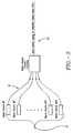
- FIG. 5illustrates an amplifier system embodiment of the present invention that includes at least 32 signal sources.
- FIG. 6is a graph illustrating the gain and optical noise figure of the two different embodiments of the present invention.
- FIG. 7illustrates an all band Raman amplifier embodiment of the present invention.
- FIG. 8 ( a )is a schematic diagram which illustrates an open loop configuration for a dispersion-managing Raman amplifier (DMRA) embodiment of the present invention using a bi-directionally pumped gain fiber.
- DMRAdispersion-managing Raman amplifier
- FIG. 8 ( b )is a schematic diagram which illustrates an open loop configuration for a DMRA embodiment of the present invention with the gain fiber split in two parts and counter-propagation for the pump and signal.
- FIG. 8 ( c )is a schematic diagram which illustrates an open loop configuration for a DMRA embodiment of the present invention with additional elements placed between two segments of the amplifier.
- FIG. 8 ( d )is a schematic view which illustrates an open loop configuration for a DMRA of the present invention with the pump inserted into a first stage counter-propagating and then sent to a second stage of the amplifier.
- FIG. 8 ( e )is a schematic view which illustrates an open loop configuration for the DMRA of the present invention with mid-stage elements.
- FIG. 8 ( f )is a schematic view which illustrates an open loop configuration for the DMRA of the present invention with bi-directional pumping used in a second stage to boost the power gain without severe degradation in noise figure for the composite amplifier.
- FIGS. 9 ( a )- 9 ( d )are schematic diagrams of illustrating hybrid systems of discrete and distributed amplifiers of the present invention.
- one embodiment of the present inventionis an amplifier apparatus 10 that includes an optical transmission line 12 with an input, an output and a Raman amplification region 14 .
- Raman amplification region 14can be a discrete Raman amplification region.
- Amplifier apparatus 10provides substantially more pump power than an EDFA in order to obtain a comparable level of signal gain.
- FIG. 2is a graph that illustrates the overall amplifier efficiency vs pump power. When the ouput power is high, the overall efficiency of amplifier apparatus 10 can exceed that of an EDFA.
- Raman amplification region 14provides a pump to signal power conversion efficiency of at least 20%, more preferably at least 25%., still more preferably at least 30%, still more preferably at least 40% and still more preferably at least 55%.
- the amplifier noise figureis less than 10 dB for use in telecommunications systems.
- the pump to signal power conversion efficiencyis the signal output power minus the signal input power divided by a pump power.
- Raman amplification region 14amplifies a signal with multiple wavelengths over at least a 30 nm range of wavelengths, more preferably over at least a 50 nm range of wavelengths and still more preferably over at least a 70 nm range of wavelengths. To obtain high-efficiency the optical losses in the components and fiber splices of amplifier apparatus 10 are preferably minimized over the pump and signal wavelength ranges. Raman amplification region 14 is selected to maximize the Raman gain coefficient (1/W km) to loss (1/km) ratio at the chosen pump wavelength(s) and to minimize loss over the signal wavelength range.
- Raman amplification region 14can have a noise figure less than 10 dB over the range of wavelengths of the signal.
- the range of wavelengths of the signalis in the range of 1400 to 1650 nm.
- a pump source 16is coupled to optical transmission line 12 .
- the total amplifier pump-to-signal efficiency of amplifier apparatus 10increases with pump power.
- the pump-to-signal conversion efficiencyis maximized at very high pump powers with relatively short gain fibers ( ⁇ Leff). This also minimizes the noise figure of amplifier apparatus 10 .
- Pump source 16produces a sufficient amount of pump power, typically at least several hundred mW of power, to achieve high efficiency. In one specific embodiment, pump source produces a pump power of at least 450 mW.
- Pump source 16can be one or more laser diodes.
- the laser diodeshave high output power, in a single-mode fiber, and a controlled output spectrum that can be achieved, for example with a Bragg grating external cavity output coupler.
- laser diodescan be polarized and include a polarization maintaining output fiber.
- two laser diodesare combined at each wavelength with a polarization beam combiner in order to achieve higher output power per wavelength and polarization-independent gain.
- WDMswavelength-division multiplexers
- An input optical signal to apparatus 10is in Raman amplification region 16 .
- a corresponding output signalhas at least 100 mW more power than the input optical signal. In other embodiments, the output signal has at least 150 mW more power than the input optical signal, or at least 200 mW more power than the input optical signal or at least 250 mW more power than the input optical signal.
- At least a portion of transmission line 12can be a dispersion compensating fiber.
- the dispersion compensating fiber portion of transmission line 12can have an absolute magnitude of dispersion of at least 50 ps/nm-km.
- amplifier apparatus 10can be only one stage in a multi-stage amplifier, particularly the stage that is located adjacent to the output.
- FIG. 5Another embodiment of the present invention, shown in FIG. 5, is an amplifier system 20 that includes at least 32 signal sources (collectively 22) that produce an input optical signal for amplifier apparatus 10 .
- amplifier apparatus 10was created with more than 4 dB of gain over 47 nm using a Lucent DK-30 dispersion compensating fiber as the gain fiber. 1 dB of loss was assumed to be present at both ends of the gain fiber.
- the gain fiberwas pumped with 380 mW at 1472 nm and 1505 nm.
- Six input signals at 1570, 1580, 1590, 1600, 1610 and 1620had 15 mW of power and were counter-propagating with respect to the pump wavelengths.
- the combined output powerwas 251 mW after passing the 1 dB loss at the end of the gain fiber.
- amplifier apparatus 10had more than 3.2 dB of gain over 105 nm utilizing a Lucent DK-20 dispersion compensating fiber. 1 dB of loss was assumed to be present at both ends of the gain fiber. This fiber was pumped with 250 mW at 1396, 1416, and 1427 nm, 150 mW at 1450 nm, 95 mW at 1472 nm and 75 mW at 1505 nm. Ten input signals at 1520, 1530, 1540, 1550, 1560, 1570, 1580, 1590, 1600 and 1610 nm had 12 mW of power and were counter-propagating with respect to the pump wavelengths.
- the combined output powerwas 284 mW after passing the 1 dB loss at the end of the gain fiber.
- FIG. 6is a graph that illustrates the gain and optical noise figure of the two different embodiments of the present invention described in the preceding two paragraphs.
- FIG. 7is a schematic diagram of one embodiment of an all band Raman amplifier 24 that includes transmission line 12 with two Raman amplification regions 14 ′ and 14 ′′. As illustrated, WDM's 26 and 28 are provided. A length of each Raman amplification region 14 ′ and 14 ′′ can be at least 200 m or at least 1 kilometer. Shorter signal wavelengths can receive more gain in one of Raman amplification regions 14 ′, 14 ′′ than in the other. One or both of Raman amplification regions 14 ′ and 14 ′′ can include dispersion compensating fiber.
- a lossy membercan be positioned between the Raman amplification regions 14 ′ and 14 ′′. The lossy member can include at least one of an add/drop multiplexer, a gain equalization element, an optical isolator or a dispersion compensating element.
- WDM 28receives a first set of pump wavelengths provided by a first pump source and WDM 26 receives a second set of pump wavelengths which can provide gain to the optical signal and extract optical energy from at least a portion of the first set of pump wavelengths.
- the second set of wavelengthsis provided by a second pump source.
- a length of each Raman amplification region 14 ′ and 14 ′′can be controllable to adjust gain flatness as a function of optical signal wavelengths.
- WDM 26can substantially pass signal wavelengths as well as at least a portion of the first set of pump wavelengths between the two Raman amplification regions 14 ′ and 14 ′′. Substantially passing signal wavelengths will be understood to mean that at least a majority of the power passes between Raman amplification regions 14 ′ and 14 ′′.
- WDM 28can be configured to substantially pass the optical signal between Raman amplification regions 14 and an output 30 .
- the first and second sets of pump wavelengthscan propagate in a downstream direction towards the input in transmission line 12 .
- a gain flatness of all band Raman amplifier 24can be optimized by a gain flattening filter, and/or by pump wavelengths, pump powers, the number of pumps and the lengths of Raman gain fibers 1410 and 1420 .
- FIGS. 8 ( a ) through 8 ( f )illustrate different open loop configurations for a dispersion-managing Raman amplifier 32 that provides dispersion compensation for transmission fiber 12 .
- transmission fiber 12is a bi-directionally pumped gain fiber.
- An optical signalis input from an input port 34 to transmission line 12 .
- Transmission line 12is pumped bi-directionally by a pumping light generated by a pumping sources 16 ′ and 16 ′′.
- Transmission line 12is single spatial mode at both the signal and pump wavelengths.
- a counter-propagating pump and signal geometrycan avoid coupling any pumping light fluctuations to the amplified signal.
- the open loop configuration of FIG. 8 ( b )achieves this by splitting transmission line 12 into two Raman gain regions 14 ′ and 14 ′′ with counter-propagation of the pump and sign.
- Pumps 16 ′ and 16 ′′are used to pump each segment, and WDM's 28 and 26 are used to couple in pumps 16 ′ and 16 ′′ respectively.
- An optical isolator 38is placed between Raman gain regions 14 ′ and 14 ′′ to avoid any interference between the pump energy from 16 ′′ and 16 ′ which might occur at WDM 28 .
- Isolator 38can be replaced by other elements including but not limited to, a gain equalization element and/or an optical add/drop multiplexer. Because of the high insertion loss associated with add/drop multiplexers, an effective isolation can be achieved between the pumps in Raman gain regions 14 ′ and 14 ′′.
- gain equalizationcan be performed at the mid-stage access in two-section transmission line 12 .
- This wavelength dependency or nonuniformity of the gain bandmay have little impact on single-channel transmission and can render amplifier 32 unsuitable for multichannel operation through a cascade of amplifiers.
- Gain-flattening elementscan significantly increase the usable bandwidth of a long chain of amplifiers.
- FIG. 8 ( d )An alternate configuration for the gain fiber pumping is also illustrated in FIG. 8 ( d ).
- transmission line 12is split into two lengths.
- Pump 16 ′is introduced into Raman gain region 14 ′′ with WDM 26 .
- the pumpis inserted into the first stage in a counter-propagating manner and then to the second stage.
- the pumpis shunted around where the signal is introduced and extracted.
- the pumpthen enters Raman gain region 14 ′.
- An optional WDM 40may be used to remove any remaining pump and minimize damage to isolator 38 .
- Isolator 38can be placed between Raman gain sections 14 ′ and 14 ′′.
- This configurationcan be characterized by one or more of the following: (i) the first stage can be a low-noise pre-amplifier, (ii) the isolator in the signal path further reduces noise, (iii) the second stage can be a power amplifier, depleting pump power, (iv) a better noise figure since weak signal sees higher gain, (v) better gain saturation performance, and (vi) prevention of double Rayleigh scattering. At the mid-stage other elements such as add/drop multiplexers can also be placed.
- FIG. 8 ( e )illustrates a two-stage embodiment with an optical add/drop multiplexer 42 at the mid-stage.
- the embodiments of FIGS. 8 ( d ) and 8 ( e )may also be used in where dispersion compensation fiber is not used as the gain fiber.
- Bi-directional pumping in the second stage of the two-stage amplifiercan increase the power amplifier gain without severely impacting the noise figure of the composite amplifier illustrated as in the bi-directional pumping embodiment of FIG. 8 ( f ).
- FIGS. 9 ( a ) through 9 ( d )illustrate different configurations of hybrid systems with discrete and distributed amplifiers of the present invention.
- FIG. 9 ( a )illustrates an embodiment where distributed amplification is added with counter-propagating Raman pumps. Alternate band pumps are added at different spatial points to minimize nonlinear interaction between pumps. In FIG. 9 ( b ), bi-directional pumping is provided. Alternate band Raman pumps can be launched in different directions to minimize interaction between pumps. The embodiment of FIG. 9 ( c ) provides bi-directional pumping and mid-stage access which provides more uniform pumping. In FIG. 9 ( d ), counter-propagating pumps are included without mid-stage access. Alternate pump bands can be launched that are orthogonally polarized. In this embodiment the Raman gain for cross-polarized light is about one-tenth the strength of Raman gain for co-polarized light.
- FIGS. 9 ( a )- 9 ( d )illustrate different pumping configurations for distributed Raman gain, or amplification of the present invention.
- FIG. 9 ( a )illustrates an embodiment with a counter-propagating pumping scheme with mid-stage access. Alternate pump bands can be spatially dispersed.
- FIG. 9 ( b )illustrates an embodiment with bi-directionally pumping without mid-stage access. Alternate pumps can be launched in different directions.
- bi-directional pumping and mid-stage accessare provided with a result that the gain can be more spatially uniform.
- FIG. 9 ( d )illustrates an embodiment with a launch of alternate pump bands that are cross-polarized.
Landscapes
- Physics & Mathematics (AREA)
- Electromagnetism (AREA)
- Engineering & Computer Science (AREA)
- Computer Networks & Wireless Communication (AREA)
- Signal Processing (AREA)
- Plasma & Fusion (AREA)
- Optics & Photonics (AREA)
- Optical Modulation, Optical Deflection, Nonlinear Optics, Optical Demodulation, Optical Logic Elements (AREA)
- Optical Communication System (AREA)
Abstract
Description
Claims (118)
Priority Applications (3)
| Application Number | Priority Date | Filing Date | Title |
|---|---|---|---|
| US09/847,949US6618192B2 (en) | 1998-06-16 | 2001-05-02 | High efficiency raman amplifier |
| AU2002305388AAU2002305388A1 (en) | 2001-05-02 | 2002-05-02 | High efficiency raman amplifier |
| PCT/US2002/014196WO2002088781A2 (en) | 2001-05-02 | 2002-05-02 | High efficiency raman amplifier |
Applications Claiming Priority (4)
| Application Number | Priority Date | Filing Date | Title |
|---|---|---|---|
| US8942698P | 1998-06-16 | 1998-06-16 | |
| US09/719,591US6985283B1 (en) | 1998-06-16 | 1999-06-16 | Fiber-optic compensation for dispersion, gain tilt, and band pump nonlinearity |
| US09/768,367US6574037B2 (en) | 1998-06-16 | 2001-01-22 | All band amplifier |
| US09/847,949US6618192B2 (en) | 1998-06-16 | 2001-05-02 | High efficiency raman amplifier |
Related Parent Applications (1)
| Application Number | Title | Priority Date | Filing Date |
|---|---|---|---|
| US09/768,367Continuation-In-PartUS6574037B2 (en) | 1998-06-16 | 2001-01-22 | All band amplifier |
Publications (2)
| Publication Number | Publication Date |
|---|---|
| US20020044335A1 US20020044335A1 (en) | 2002-04-18 |
| US6618192B2true US6618192B2 (en) | 2003-09-09 |
Family
ID=25301919
Family Applications (1)
| Application Number | Title | Priority Date | Filing Date |
|---|---|---|---|
| US09/847,949Expired - LifetimeUS6618192B2 (en) | 1998-06-16 | 2001-05-02 | High efficiency raman amplifier |
Country Status (3)
| Country | Link |
|---|---|
| US (1) | US6618192B2 (en) |
| AU (1) | AU2002305388A1 (en) |
| WO (1) | WO2002088781A2 (en) |
Cited By (4)
| Publication number | Priority date | Publication date | Assignee | Title |
|---|---|---|---|---|
| US20020163710A1 (en)* | 2001-04-12 | 2002-11-07 | Andrew Ellis | Composite optical amplifier |
| US20030021013A1 (en)* | 2000-03-02 | 2003-01-30 | Peter Krummrich | Method for transmitting additional optical signals in the s-band |
| US20050195472A1 (en)* | 2004-02-13 | 2005-09-08 | Tang Yin S. | Integration of rare-earth doped amplifiers into semiconductor structures and uses of same |
| US20070223085A1 (en)* | 2002-07-31 | 2007-09-27 | Pirelli & C S.P.A. | Multi-stage Raman amplifier |
Families Citing this family (5)
| Publication number | Priority date | Publication date | Assignee | Title |
|---|---|---|---|---|
| US7197245B1 (en)* | 2002-03-15 | 2007-03-27 | Xtera Communications, Inc. | System and method for managing system margin |
| GB2387478A (en)* | 2002-04-12 | 2003-10-15 | Marconi Comm Ltd | Raman optical amplifier |
| WO2003091789A1 (en)* | 2002-04-24 | 2003-11-06 | Pirelli & C. S.P.A. | Optical devices comprising series of birefringent waveplates |
| JP4560300B2 (en)* | 2004-02-05 | 2010-10-13 | 富士通株式会社 | Raman optical amplifier, optical transmission system using the same, and Raman optical amplification method |
| CN102307117A (en)* | 2011-07-18 | 2012-01-04 | 北京星网锐捷网络技术有限公司 | Port configuration method and device |
Citations (48)
| Publication number | Priority date | Publication date | Assignee | Title |
|---|---|---|---|---|
| US4881790A (en)* | 1988-04-25 | 1989-11-21 | American Telephone And Telegraph Company, At&T Bell Laboratories | Optical communications system comprising raman amplification means |
| US4932739A (en) | 1989-09-25 | 1990-06-12 | At&T Bell Laboratories | Ultra-fast optical logic devices |
| US4952059A (en) | 1986-06-06 | 1990-08-28 | The Board Of Trustees Of The Leland Stanford Junior University | Reentrant fiber raman gyroscope |
| US4995690A (en) | 1989-04-24 | 1991-02-26 | Islam Mohammed N | Modulation instability-based fiber interferometric switch |
| EP0421675A2 (en) | 1989-10-06 | 1991-04-10 | AT&T Corp. | Distributed amplification for lightwave transmission system |
| US5020050A (en) | 1989-10-13 | 1991-05-28 | At&T Bell Laboratories | Cascadable optical combinatorial logic gates |
| US5078464A (en) | 1990-11-07 | 1992-01-07 | At&T Bell Laboratories | Optical logic device |
| US5101456A (en) | 1990-11-07 | 1992-03-31 | At&T Bell Laboratories | Predistortion apparatus for optical logic device |
| US5115488A (en) | 1991-04-02 | 1992-05-19 | At&T Bell Laboratories | Apparatus comprising an all-optical gate |
| US5191628A (en) | 1990-11-09 | 1993-03-02 | Northern Telecom Limited | Optical amplifiers |
| US5224194A (en) | 1991-04-02 | 1993-06-29 | At&T Bell Laboratories | All-optical timing restoration |
| US5257124A (en) | 1991-08-15 | 1993-10-26 | General Instrument Corporation | Low distortion laser system for AM fiber optic communication |
| US5295209A (en) | 1991-03-12 | 1994-03-15 | General Instrument Corporation | Spontaneous emission source having high spectral density at a desired wavelength |
| US5485536A (en) | 1994-10-13 | 1996-01-16 | Accuphotonics, Inc. | Fiber optic probe for near field optical microscopy |
| US5497386A (en) | 1993-09-16 | 1996-03-05 | Pirelli Cavi S.P.A. | Optical-fibre passively mode locked laser generator with non-linear polarization switching |
| US5513194A (en) | 1994-06-30 | 1996-04-30 | Massachusetts Institute Of Technology | Stretched-pulse fiber laser |
| JPH09197452A (en) | 1996-01-16 | 1997-07-31 | Nec Corp | Optical fiber communication system |
| US5664036A (en) | 1994-10-13 | 1997-09-02 | Accuphotonics, Inc. | High resolution fiber optic probe for near field optical microscopy and method of making same |
| EP0841764A2 (en) | 1996-11-06 | 1998-05-13 | Corning Incorporated | Crosstalk suppression in a multipath optical amplifier |
| US5768012A (en) | 1997-03-07 | 1998-06-16 | Sdl, Inc. | Apparatus and method for the high-power pumping of fiber optic amplifiers |
| US5778014A (en) | 1996-12-23 | 1998-07-07 | Islam; Mohammed N. | Sagnac raman amplifiers and cascade lasers |
| US5796909A (en) | 1996-02-14 | 1998-08-18 | Islam; Mohammed N. | All-fiber, high-sensitivity, near-field optical microscopy instrument employing guided wave light collector and specimen support |
| US5798853A (en) | 1992-10-16 | 1998-08-25 | Fujitsu, Limited | Optical communication system compensating for chromatic dispersion and phase conjugate light generator for use therewith |
| US5815518A (en) | 1997-06-06 | 1998-09-29 | Lucent Technologies Inc. | Article comprising a cascaded raman fiber laser |
| FR2764452A1 (en) | 1997-06-06 | 1998-12-11 | Nec Corp | Optical signal level adjustment system for optical fibre communications |
| EP0903877A2 (en) | 1997-09-12 | 1999-03-24 | Lucent Technologies Inc. | Optical fiber dispersion compensation |
| US5905838A (en) | 1998-02-18 | 1999-05-18 | Lucent Technologies Inc. | Dual window WDM optical fiber communication |
| WO1999041855A2 (en) | 1998-02-16 | 1999-08-19 | Koninklijke Philips Electronics N.V. | Optical transmission system with a receiver using full optical clock recovery |
| WO1999048176A1 (en) | 1998-03-20 | 1999-09-23 | Bandwidth Solutions, Inc. | Chirped period gratings for raman amplification in circulator loop cavities |
| WO1999049580A2 (en) | 1998-03-24 | 1999-09-30 | Xtera Communications, Inc. | NONLINEAR FIBER AMPLIFIERS FOR 1430-1530mm RADIATION |
| WO1999062407A1 (en) | 1998-06-05 | 1999-12-09 | Amei Technologies, Inc. | Apparatus and method for placing sutures, e.g. at a tendon laceration |
| US6043927A (en) | 1997-06-26 | 2000-03-28 | University Of Michigan | Modulation instability wavelength converter |
| US6052393A (en) | 1996-12-23 | 2000-04-18 | The Regents Of The University Of Michigan | Broadband Sagnac Raman amplifiers and cascade lasers |
| US6081355A (en) | 1996-03-08 | 2000-06-27 | Kabushiki Kaisha Toshiba | Multi-wavelength light source |
| US6081366A (en)* | 1997-08-28 | 2000-06-27 | Lucent Technologies Inc. | Optical fiber communication system with a distributed Raman amplifier and a remotely pumped er-doped fiber amplifier |
| US6104733A (en) | 1998-03-11 | 2000-08-15 | Lucent Technologies Inc. | Multi-stage optical fiber amplifier having high conversion efficiency |
| US6147794A (en) | 1999-02-04 | 2000-11-14 | Lucent Technologies, Inc. | Raman amplifier with pump source for improved performance |
| EP1054489A2 (en) | 1999-05-19 | 2000-11-22 | Alcatel | An optical amplifier |
| WO2001052372A1 (en) | 2000-01-12 | 2001-07-19 | Xtera Communications, Inc. | Raman amplifier with bi-directional pumping |
| US20010014194A1 (en) | 2000-02-10 | 2001-08-16 | Sumitomo Electric Industries, Ltd. | Raman amplifier, optical transmission system and optical fiber |
| WO2001078264A2 (en) | 2000-02-14 | 2001-10-18 | Xtera Communications, Inc. | Nonlinear optical loop mirror |
| WO2001078263A2 (en) | 2000-04-11 | 2001-10-18 | Xtera Communications, Inc. | Broadband amplifier and communication system |
| WO2001076350A2 (en) | 2000-04-11 | 2001-10-18 | Xtera Communications, Inc. | Broadband amplifier and communication system |
| US6310716B1 (en) | 2000-08-18 | 2001-10-30 | Corning Incorporated | Amplifier system with a discrete Raman fiber amplifier module |
| US6320884B1 (en) | 1998-02-26 | 2001-11-20 | Tycom (Us) Inc., | Wide bandwidth Raman amplifier employing a pump unit generating a plurality of wavelengths |
| US6335820B1 (en) | 1999-12-23 | 2002-01-01 | Xtera Communications, Inc. | Multi-stage optical amplifier and broadband communication system |
| US6359725B1 (en) | 1998-06-16 | 2002-03-19 | Xtera Communications, Inc. | Multi-stage optical amplifier and broadband communication system |
| US6381391B1 (en) | 1999-02-19 | 2002-04-30 | The Regents Of The University Of Michigan | Method and system for generating a broadband spectral continuum and continuous wave-generating system utilizing same |
Family Cites Families (2)
| Publication number | Priority date | Publication date | Assignee | Title |
|---|---|---|---|---|
| US5790300A (en)* | 1996-10-15 | 1998-08-04 | Mcdonnell Douglas Corporation | Multi-channel fiber amplification system and associated method |
| US6163636A (en)* | 1999-01-19 | 2000-12-19 | Lucent Technologies Inc. | Optical communication system using multiple-order Raman amplifiers |
- 2001
- 2001-05-02USUS09/847,949patent/US6618192B2/ennot_activeExpired - Lifetime
- 2002
- 2002-05-02AUAU2002305388Apatent/AU2002305388A1/ennot_activeAbandoned
- 2002-05-02WOPCT/US2002/014196patent/WO2002088781A2/ennot_activeApplication Discontinuation
Patent Citations (55)
| Publication number | Priority date | Publication date | Assignee | Title |
|---|---|---|---|---|
| US4952059A (en) | 1986-06-06 | 1990-08-28 | The Board Of Trustees Of The Leland Stanford Junior University | Reentrant fiber raman gyroscope |
| US4881790A (en)* | 1988-04-25 | 1989-11-21 | American Telephone And Telegraph Company, At&T Bell Laboratories | Optical communications system comprising raman amplification means |
| US4995690A (en) | 1989-04-24 | 1991-02-26 | Islam Mohammed N | Modulation instability-based fiber interferometric switch |
| US4932739A (en) | 1989-09-25 | 1990-06-12 | At&T Bell Laboratories | Ultra-fast optical logic devices |
| EP0421675A2 (en) | 1989-10-06 | 1991-04-10 | AT&T Corp. | Distributed amplification for lightwave transmission system |
| US5020050A (en) | 1989-10-13 | 1991-05-28 | At&T Bell Laboratories | Cascadable optical combinatorial logic gates |
| US5078464A (en) | 1990-11-07 | 1992-01-07 | At&T Bell Laboratories | Optical logic device |
| US5101456A (en) | 1990-11-07 | 1992-03-31 | At&T Bell Laboratories | Predistortion apparatus for optical logic device |
| US5191628A (en) | 1990-11-09 | 1993-03-02 | Northern Telecom Limited | Optical amplifiers |
| US5295209A (en) | 1991-03-12 | 1994-03-15 | General Instrument Corporation | Spontaneous emission source having high spectral density at a desired wavelength |
| US5224194A (en) | 1991-04-02 | 1993-06-29 | At&T Bell Laboratories | All-optical timing restoration |
| US5369519A (en) | 1991-04-02 | 1994-11-29 | At&T Bell Laboratories | All-optical timing restoration |
| US5115488A (en) | 1991-04-02 | 1992-05-19 | At&T Bell Laboratories | Apparatus comprising an all-optical gate |
| US5257124A (en) | 1991-08-15 | 1993-10-26 | General Instrument Corporation | Low distortion laser system for AM fiber optic communication |
| US5798853A (en) | 1992-10-16 | 1998-08-25 | Fujitsu, Limited | Optical communication system compensating for chromatic dispersion and phase conjugate light generator for use therewith |
| US5497386A (en) | 1993-09-16 | 1996-03-05 | Pirelli Cavi S.P.A. | Optical-fibre passively mode locked laser generator with non-linear polarization switching |
| US5513194A (en) | 1994-06-30 | 1996-04-30 | Massachusetts Institute Of Technology | Stretched-pulse fiber laser |
| US5485536A (en) | 1994-10-13 | 1996-01-16 | Accuphotonics, Inc. | Fiber optic probe for near field optical microscopy |
| US5664036A (en) | 1994-10-13 | 1997-09-02 | Accuphotonics, Inc. | High resolution fiber optic probe for near field optical microscopy and method of making same |
| JPH09197452A (en) | 1996-01-16 | 1997-07-31 | Nec Corp | Optical fiber communication system |
| US5796909A (en) | 1996-02-14 | 1998-08-18 | Islam; Mohammed N. | All-fiber, high-sensitivity, near-field optical microscopy instrument employing guided wave light collector and specimen support |
| US6081355A (en) | 1996-03-08 | 2000-06-27 | Kabushiki Kaisha Toshiba | Multi-wavelength light source |
| EP0841764A2 (en) | 1996-11-06 | 1998-05-13 | Corning Incorporated | Crosstalk suppression in a multipath optical amplifier |
| US6370164B1 (en) | 1996-12-23 | 2002-04-09 | Xtera Communications, Inc. | Broadband sagnac raman amplifiers and cascade lasers |
| US5778014A (en) | 1996-12-23 | 1998-07-07 | Islam; Mohammed N. | Sagnac raman amplifiers and cascade lasers |
| US6052393A (en) | 1996-12-23 | 2000-04-18 | The Regents Of The University Of Michigan | Broadband Sagnac Raman amplifiers and cascade lasers |
| US5768012A (en) | 1997-03-07 | 1998-06-16 | Sdl, Inc. | Apparatus and method for the high-power pumping of fiber optic amplifiers |
| US5815518A (en) | 1997-06-06 | 1998-09-29 | Lucent Technologies Inc. | Article comprising a cascaded raman fiber laser |
| FR2764452A1 (en) | 1997-06-06 | 1998-12-11 | Nec Corp | Optical signal level adjustment system for optical fibre communications |
| US6043927A (en) | 1997-06-26 | 2000-03-28 | University Of Michigan | Modulation instability wavelength converter |
| US6081366A (en)* | 1997-08-28 | 2000-06-27 | Lucent Technologies Inc. | Optical fiber communication system with a distributed Raman amplifier and a remotely pumped er-doped fiber amplifier |
| EP0903877A2 (en) | 1997-09-12 | 1999-03-24 | Lucent Technologies Inc. | Optical fiber dispersion compensation |
| WO1999041855A2 (en) | 1998-02-16 | 1999-08-19 | Koninklijke Philips Electronics N.V. | Optical transmission system with a receiver using full optical clock recovery |
| US5905838A (en) | 1998-02-18 | 1999-05-18 | Lucent Technologies Inc. | Dual window WDM optical fiber communication |
| US6320884B1 (en) | 1998-02-26 | 2001-11-20 | Tycom (Us) Inc., | Wide bandwidth Raman amplifier employing a pump unit generating a plurality of wavelengths |
| US6104733A (en) | 1998-03-11 | 2000-08-15 | Lucent Technologies Inc. | Multi-stage optical fiber amplifier having high conversion efficiency |
| US6374006B1 (en) | 1998-03-20 | 2002-04-16 | Xtera Communications, Inc. | Chirped period gratings for raman amplification in circulator loop cavities |
| WO1999048176A1 (en) | 1998-03-20 | 1999-09-23 | Bandwidth Solutions, Inc. | Chirped period gratings for raman amplification in circulator loop cavities |
| US6101024A (en) | 1998-03-24 | 2000-08-08 | Xtera Communications, Inc. | Nonlinear fiber amplifiers used for a 1430-1530nm low-loss window in optical fibers |
| US6239903B1 (en) | 1998-03-24 | 2001-05-29 | Xtera Communications, Inc. | Nonlinear fiber amplifiers for a 1430-1530nm low-loss window in optical fibers |
| US6239902B1 (en) | 1998-03-24 | 2001-05-29 | Xtera Communciations Inc. | Nonlinear fiber amplifiers used for a 1430-1530nm low-loss window in optical fibers |
| US6356384B1 (en) | 1998-03-24 | 2002-03-12 | Xtera Communications Inc. | Broadband amplifier and communication system |
| WO1999049580A2 (en) | 1998-03-24 | 1999-09-30 | Xtera Communications, Inc. | NONLINEAR FIBER AMPLIFIERS FOR 1430-1530mm RADIATION |
| WO1999062407A1 (en) | 1998-06-05 | 1999-12-09 | Amei Technologies, Inc. | Apparatus and method for placing sutures, e.g. at a tendon laceration |
| US6359725B1 (en) | 1998-06-16 | 2002-03-19 | Xtera Communications, Inc. | Multi-stage optical amplifier and broadband communication system |
| US6147794A (en) | 1999-02-04 | 2000-11-14 | Lucent Technologies, Inc. | Raman amplifier with pump source for improved performance |
| US6381391B1 (en) | 1999-02-19 | 2002-04-30 | The Regents Of The University Of Michigan | Method and system for generating a broadband spectral continuum and continuous wave-generating system utilizing same |
| EP1054489A2 (en) | 1999-05-19 | 2000-11-22 | Alcatel | An optical amplifier |
| US6335820B1 (en) | 1999-12-23 | 2002-01-01 | Xtera Communications, Inc. | Multi-stage optical amplifier and broadband communication system |
| WO2001052372A1 (en) | 2000-01-12 | 2001-07-19 | Xtera Communications, Inc. | Raman amplifier with bi-directional pumping |
| US20010014194A1 (en) | 2000-02-10 | 2001-08-16 | Sumitomo Electric Industries, Ltd. | Raman amplifier, optical transmission system and optical fiber |
| WO2001078264A2 (en) | 2000-02-14 | 2001-10-18 | Xtera Communications, Inc. | Nonlinear optical loop mirror |
| WO2001076350A2 (en) | 2000-04-11 | 2001-10-18 | Xtera Communications, Inc. | Broadband amplifier and communication system |
| WO2001078263A2 (en) | 2000-04-11 | 2001-10-18 | Xtera Communications, Inc. | Broadband amplifier and communication system |
| US6310716B1 (en) | 2000-08-18 | 2001-10-30 | Corning Incorporated | Amplifier system with a discrete Raman fiber amplifier module |
Non-Patent Citations (44)
| Title |
|---|
| Agrawal, "Fiber-Optic Communication Systems," Second Edition, Basic Concepts, 2nd Ed. John Wiley & Sons, pp. 365-366, 1997. |
| Arend et al., "A nonlinear amplifying loop mirror operating with wavelength division multiplexed data," LEOS, vol. 2, pp. 479-480, 1999. |
| Aso et al. Recent Advances in Ultra-Broadband Fiberoptics Wavelength Converters. Lasers and Electro-Optics Society 2000 Annual Meeting. Nov. 13-16, 2000, pp. 683-684. vol. 2.** |
| Becker et al., "Erbium Doped Fiber Amplifiers Fundamentals and Technology," Academic Press, pp. 55-60, 1999. |
| Emori et al., "100nm bandwidth flat-gain Raman amplifiers pumped and gain-equalised by 12-wavelength-channel WDM laser diode unit," Electronics Letters, vol. 35, No. 16, pp. 1355-1356, Aug. 5, 1999. |
| Emori et al., "Cost-effective depolarized diode pump unit designed for C-band flat-gain Raman amplifiers to control EDFA gain profile," OFC 2000-1, pp. 106-108, Mar. 7-10, 2000. |
| F. Di Pasquale, G. Grasso, F. Meli, G Sacchi, and S. Turolla (1999), 23 dBm Output Power Er/Yb Co-Doped Fiber Amplifier for WDM Signals in the 1575-1605 nm Wavelength region, OFC 1999 Tecnical Digest, paper WA2 pp. 4-6. |
| Fludger et al. An Analysis of the Improvements in OSNR from Distributed Raman Amplifiers Using Modern Transmission Fibres. OFCC Mar. 7-10, 2000. pp. 100-102. vol. 4.** |
| Fludger et al. Fundamental Noise Limits in Broadband Raman Amplifiers. OFCC Mar. 17-22, 2001. pp. MA5/1- MA5/3, vol. 1.** |
| Hamoir et al. Raman Amplifier with a conversion efficiency in excess of 20%. Optical Amplifiers and their Applications Conference. 1999. pp. 165-167.** |
| Jackson, Stuart. Theoretical Characterization of Raman Oscillation with Intracavity Pumping of Fiber Lasers. IEEE Journal of Quantum Electronics, vol. 37, No. 5, May 2001, pp. 626-634.** |
| Koch et al., "Broadband gain flattened Raman Amplifier to extend operation in the third telecommunication window," OFC 2000, pp. 103-105, Mar. 7-10, 2000. |
| Leng et al., "8-channel WDM soliton amplification and signal recovery," ECOC, vol. 1, pp. 105-106, Sep. 20-24, 1998. |
| Lew Goldberg and Jeffrey Koplow, "High Power Side-Pumped Er/Yb Dobed Fiber Amplifier", OFC 1999 Technical Digest, paper WA7 pp. 19-21. |
| Lewis et al. Low-Noise High Gain Dispersion Compensating Broadband Raman Amplifier. OFCC Mar. 7-10, 2000, pp. 5-7, vol. 1.** |
| Lewis et al., "Gain and saturation characteristics of dual-wavelength-pumped silica-fibre Raman amplifiers," Electronics Letters, vol. 35, No. 14, pp. 1178-1179, Jul. 08, 1999. |
| Namiki et al. Recent Advances in Ultra-Wideband Raman Amplfiers. OFCC Mar. 7-10, 2000. pp. 98-99, vol. 4.** |
| Nielsen et al., "3.28 Tb/s (82×40 Gb/s) transmission over 3 × 100 km nonzero-dispersion fiber using dual C- and L-band hybrid Raman/Erbium-doped inline amplifiers," OFCC 2000, pp. 1229-1231, Mar. 7-10, 2000. |
| Nielsen et al., "3.28 Tb/s (82x40 Gb/s) transmission over 3 x 100 km nonzero-dispersion fiber using dual C- and L-band hybrid Raman/Erbium-doped inline amplifiers," OFCC 2000, pp. 1229-1231, Mar. 7-10, 2000. |
| Nissov et al, "Rayleigh crosstalk in long cascades of distributed unsaturated Raman amplifiers," Electronics Letters, vol. 35, No. 12, pp. 997-998, Jun. 10, 1999. |
| Paul Freeman, Dan Ratoff, Dave Mehuys, Ray Zanoni, and Mark Laliberte, "High Capacity EDFA with Output Power to Support Densley Loaded Channels", OFC 1999 Technical Digest, paper WA6 pp. 16-18. |
| PCT/US01/05089 International Search Report Completed Nov. 23, 2001.** |
| PCT/US01/11894 International Search Report Completed Jan. 16, 2002.** |
| PCT/US99/06231 International Search Report Completed May 12, 1999.** |
| PCT/US99/06428 International Search Report Completed Jun. 18, 1999.** |
| Pending Patent Application; USSN 09/765,972; entitled "S+ Band Nonlinear Polarization Amplifiers," pp. 1-30, Filed Jan. 19, 2001. |
| Pending Patent Application; USSN 09/811,103; entitled "System and Method for Wide Band Raman Amplification," pp. 1-63, Filed Mar. 16, 2001. |
| Pending Patent Application; USSN 09/866,497; entitled "Nonlinear Fiber Amplifiers Used for A 1430-1530nm Low-Loss Window In Optical Fibers," pp. 1-29, Filed May 25, 2001. |
| Pending Patent Application; USSN 09/990,142; entitled "Broadband Amplifier and Communication System," pp. 1-20, Filed Nov. 20, 2001. |
| Pending Patent Application; USSN 10/003,199; entitled "Broadband Amplifier and Communication System," pp. 1-21, Filed Oct. 30, 2001. |
| Provino et al. Broadband and Nearly Flat Parametric Gain in Single-Mode Fibers. Lasers and Electro-Optics Society 2000 Annual Meeting. Nov. 13-16, 2000, pp. 683-684. vol. 2.** |
| Rini et al. Numerical Modeling and Optimization of Cascaded CW Raman Fiber Lasers. IEEE Journal of Quantum Electronics, vol. 36, No. 10, Oct. 2000. pp. 1117-1122.** |
| Roy et al. 48% Power Conversion Efficiency in a Single-Pump Gain-Shifted Thulium-Doped Fiber Amplifier. OFCC Mar. 17-22, 2001. pp. 17-22, vol. 4.** |
| S.A.E. Lewis, S.V. Chernikov, and J.R. Taylor, "1.4W Saturated Output Power From a Fibre Raman Amplifier", OFC 1999 Technical Digest, paper WG5 pp. 114-116. |
| Seo et al., "Compensation of Raman-Induced Crosstalk Using a Lumped Germanosilicate Fiber Raman Amplifier in the 1.571-1.591-mum Region," IEEE Photonics Technology Letters, vol. 13, No. 1, pp. 28-30, Jan. 2001. |
| Seo et al., "Compensation of Raman-Induced Crosstalk Using a Lumped Germanosilicate Fiber Raman Amplifier in the 1.571-1.591-μm Region," IEEE Photonics Technology Letters, vol. 13, No. 1, pp. 28-30, Jan. 2001. |
| Seo et al., "Simultaneous Amplification and Channel Equalization Using Raman Amplifier and Channel Equalization Using Raman Amplifier for 30 Channels in 1.3-mum Band," Journal of Lightwave Technology, vol. 19, No. 3, pp. 391-397, Mar. 2001. |
| Seo et al., "Simultaneous Amplification and Channel Equalization Using Raman Amplifier and Channel Equalization Using Raman Amplifier for 30 Channels in 1.3-μm Band," Journal of Lightwave Technology, vol. 19, No. 3, pp. 391-397, Mar. 2001. |
| Song et al., "Sensitivity improvement for NRZ optical systems using NALM and narrow-band filter," LEOS, vol. 2, pp. 111-112, Nov. 18-19, 1996. |
| Stolen et al., "Parametric Amplification and Frequency Conversion in Optical Fibers," IEEE Journal of Quantum Electronics, vol. QE-18, No. 7, pp. 1062-1072, Jul. 1982. |
| Suzuki et al., "50 GHz spaced, 32 × 10 Gbit/s dense WDM transmission in zero-dispersion region over 640km of dispersion-shifted fibre with multiwavelength distributed Raman amplification," Electronics Letters, vol. 35, No. 14, pp. 1175-1176, Jul. 8, 1999. |
| Suzuki et al., "50 GHz spaced, 32 x 10 Gbit/s dense WDM transmission in zero-dispersion region over 640km of dispersion-shifted fibre with multiwavelength distributed Raman amplification," Electronics Letters, vol. 35, No. 14, pp. 1175-1176, Jul. 8, 1999. |
| Vareille et al. Numerical Optimisation of Power Conversion Efficiency in 1480nm Multi-Stokes Raman Fibre Lasers. Electronics Letters. 2nd Apr. 1998, vol. 34, No. 7. pp. 675-676.** |
| Yun et al., "Dynamic Erbium-Doped Fiber Amplifier Based on Active Gain Flattening with Fiber Acoustooptic Tunable Filters," IEEE Photonics Technology Letters, vol. 11, No. 10, pp. 1229-1231, Oct. 1999. |
Cited By (8)
| Publication number | Priority date | Publication date | Assignee | Title |
|---|---|---|---|---|
| US20030021013A1 (en)* | 2000-03-02 | 2003-01-30 | Peter Krummrich | Method for transmitting additional optical signals in the s-band |
| US6937386B2 (en)* | 2000-03-02 | 2005-08-30 | Siemens Aktiengesellschaft | Method for transmitting additional optical signals in the s+band |
| US20020163710A1 (en)* | 2001-04-12 | 2002-11-07 | Andrew Ellis | Composite optical amplifier |
| US20070223085A1 (en)* | 2002-07-31 | 2007-09-27 | Pirelli & C S.P.A. | Multi-stage Raman amplifier |
| US7813034B2 (en) | 2002-07-31 | 2010-10-12 | Pgt Photonics S.P.A. | Multi-stage Raman amplifier |
| US8300306B2 (en) | 2002-07-31 | 2012-10-30 | Google Inc. | Multi-stage raman amplifier |
| US20050195472A1 (en)* | 2004-02-13 | 2005-09-08 | Tang Yin S. | Integration of rare-earth doped amplifiers into semiconductor structures and uses of same |
| US7440180B2 (en) | 2004-02-13 | 2008-10-21 | Tang Yin S | Integration of rare-earth doped amplifiers into semiconductor structures and uses of same |
Also Published As
| Publication number | Publication date |
|---|---|
| AU2002305388A1 (en) | 2002-11-11 |
| US20020044335A1 (en) | 2002-04-18 |
| WO2002088781A2 (en) | 2002-11-07 |
| WO2002088781A3 (en) | 2003-12-18 |
Similar Documents
| Publication | Publication Date | Title |
|---|---|---|
| US6356384B1 (en) | Broadband amplifier and communication system | |
| US6437906B1 (en) | All-optical gain controlled L-band EDFA structure with reduced four-wave mixing cross-talk | |
| CA2267775C (en) | A multi-wavelength optical pump | |
| EP1263096B1 (en) | Improved wide band erbium-doped fiber amplifier (EDFA) | |
| US7085039B2 (en) | Hybrid Raman/erbium-doped fiber amplifier and transmission system with dispersion map | |
| US6885498B2 (en) | Multi-stage optical amplifier and broadband communication system | |
| US20020181091A1 (en) | Wide band erbium-doped fiber amplifier (EDFA) | |
| US6417961B1 (en) | Optical amplifiers with dispersion compensation | |
| EP0883217B1 (en) | Optical fiber telecommunication system | |
| US6813065B2 (en) | Raman amplifier and optical communication system | |
| US8081880B2 (en) | Inline pump sharing architecture for remotely-pumped pre- and post-amplifiers | |
| KR100407825B1 (en) | Low noise dispersion compensating hybrid-type optical fiber amplifier | |
| US6359728B1 (en) | Pump device for pumping an active fiber of an optical amplifier and corresponding optical amplifier | |
| US6618192B2 (en) | High efficiency raman amplifier | |
| US6927898B2 (en) | Ultra-wide bandwidth optical amplifier | |
| KR100396510B1 (en) | Dispersion-compensated optical fiber amplifier | |
| EP1531563B1 (en) | Multiple order raman amplifier | |
| US20040091003A1 (en) | Optical amplifying apparatus | |
| US6631028B1 (en) | Broadband amplifier and communication system | |
| KR100446541B1 (en) | Dispersion-compensated raman optical fiber amplifier | |
| EP1460736A1 (en) | Multiwavelength depolarized raman pumps | |
| US6456425B1 (en) | Method and apparatus to perform lumped raman amplification | |
| JP2000124529A (en) | Wide band light amplifier | |
| US20030123141A1 (en) | L band optical amplifier | |
| CA2615306C (en) | Inline pump sharing architecture for remotely-pumped pre-and post-amplifiers |
Legal Events
| Date | Code | Title | Description |
|---|---|---|---|
| AS | Assignment | Owner name:XTERA COMMUNICATIONS, INC., TEXAS Free format text:ASSIGNMENT OF ASSIGNORS INTEREST;ASSIGNORS:ISLAM, MOHAMMED N.;DEWILDE, CARL;FREEMAN, MICHAEL;REEL/FRAME:012108/0507;SIGNING DATES FROM 20010601 TO 20010605 | |
| AS | Assignment | Owner name:COMERICA BANK-CALIFORNIA, TEXAS Free format text:SECURITY INTEREST;ASSIGNOR:XTERA COMMUNICATIONS, INC.;REEL/FRAME:013216/0781 Effective date:20020328 | |
| STCF | Information on status: patent grant | Free format text:PATENTED CASE | |
| AS | Assignment | Owner name:HORIZON TECHNOLOGY FUNDING COMPANY LLC, CONNECTICU Free format text:SECURITY INTEREST;ASSIGNOR:XTERA COMMUNICATIONS, INC.;REEL/FRAME:016283/0509 Effective date:20041026 | |
| FEPP | Fee payment procedure | Free format text:PAT HOLDER CLAIMS SMALL ENTITY STATUS, ENTITY STATUS SET TO SMALL (ORIGINAL EVENT CODE: LTOS); ENTITY STATUS OF PATENT OWNER: LARGE ENTITY | |
| FPAY | Fee payment | Year of fee payment:4 | |
| FPAY | Fee payment | Year of fee payment:8 | |
| AS | Assignment | Owner name:XTERA COMMUNICATIONS, INC., TEXAS Free format text:RELEASE BY SECURED PARTY;ASSIGNOR:COMERICA BANK, A TEXAS BANKING ASSOCIATION, SUCCESSOR IN INTEREST TO COMERICA BANK-CALIFORNIA;REEL/FRAME:027944/0242 Effective date:20120315 | |
| FPAY | Fee payment | Year of fee payment:12 | |
| AS | Assignment | Owner name:SQUARE 1 BANK, NORTH CAROLINA Free format text:SECURITY INTEREST;ASSIGNOR:XTERA COMMUNICATIONS, INC.;REEL/FRAME:036795/0849 Effective date:20150116 | |
| AS | Assignment | Owner name:NEPTUNE SUBSEA IP LIMITED, UNITED KINGDOM Free format text:ASSIGNMENT OF ASSIGNORS INTEREST;ASSIGNORS:XTERA COMMUNICATIONS, INC.;XTERA COMMUNICATIONS LTD.;XTERA COMMUNICATIONS CANADA, INC.;AND OTHERS;REEL/FRAME:042586/0916 Effective date:20170213 | |
| FEPP | Fee payment procedure | Free format text:ENTITY STATUS SET TO UNDISCOUNTED (ORIGINAL EVENT CODE: BIG.) |