US6617929B2 - Full output matching apparatus of a microwave doherty amplifier - Google Patents
Full output matching apparatus of a microwave doherty amplifierDownload PDFInfo
- Publication number
- US6617929B2 US6617929B2US10/076,636US7663602AUS6617929B2US 6617929 B2US6617929 B2US 6617929B2US 7663602 AUS7663602 AUS 7663602AUS 6617929 B2US6617929 B2US 6617929B2
- Authority
- US
- United States
- Prior art keywords
- amplifier
- output
- phase
- impedance
- matching circuit
- Prior art date
- Legal status (The legal status is an assumption and is not a legal conclusion. Google has not performed a legal analysis and makes no representation as to the accuracy of the status listed.)
- Expired - Lifetime
Links
Images


Classifications
- H—ELECTRICITY
- H03—ELECTRONIC CIRCUITRY
- H03F—AMPLIFIERS
- H03F1/00—Details of amplifiers with only discharge tubes, only semiconductor devices or only unspecified devices as amplifying elements
- H03F1/02—Modifications of amplifiers to raise the efficiency, e.g. gliding Class A stages, use of an auxiliary oscillation
- H03F1/04—Modifications of amplifiers to raise the efficiency, e.g. gliding Class A stages, use of an auxiliary oscillation in discharge-tube amplifiers
- H03F1/06—Modifications of amplifiers to raise the efficiency, e.g. gliding Class A stages, use of an auxiliary oscillation in discharge-tube amplifiers to raise the efficiency of amplifying modulated radio frequency waves; to raise the efficiency of amplifiers acting also as modulators
- H03F1/07—Doherty-type amplifiers
- H—ELECTRICITY
- H03—ELECTRONIC CIRCUITRY
- H03F—AMPLIFIERS
- H03F1/00—Details of amplifiers with only discharge tubes, only semiconductor devices or only unspecified devices as amplifying elements
- H03F1/56—Modifications of input or output impedances, not otherwise provided for
- H—ELECTRICITY
- H03—ELECTRONIC CIRCUITRY
- H03F—AMPLIFIERS
- H03F1/00—Details of amplifiers with only discharge tubes, only semiconductor devices or only unspecified devices as amplifying elements
- H03F1/02—Modifications of amplifiers to raise the efficiency, e.g. gliding Class A stages, use of an auxiliary oscillation
- H03F1/0205—Modifications of amplifiers to raise the efficiency, e.g. gliding Class A stages, use of an auxiliary oscillation in transistor amplifiers
- H03F1/0288—Modifications of amplifiers to raise the efficiency, e.g. gliding Class A stages, use of an auxiliary oscillation in transistor amplifiers using a main and one or several auxiliary peaking amplifiers whereby the load is connected to the main amplifier using an impedance inverter, e.g. Doherty amplifiers
- H—ELECTRICITY
- H03—ELECTRONIC CIRCUITRY
- H03F—AMPLIFIERS
- H03F3/00—Amplifiers with only discharge tubes or only semiconductor devices as amplifying elements
- H03F3/60—Amplifiers in which coupling networks have distributed constants, e.g. with waveguide resonators
- H03F3/602—Combinations of several amplifiers
- H03F3/604—Combinations of several amplifiers using FET's
- H—ELECTRICITY
- H03—ELECTRONIC CIRCUITRY
- H03F—AMPLIFIERS
- H03F2200/00—Indexing scheme relating to amplifiers
- H03F2200/387—A circuit being added at the output of an amplifier to adapt the output impedance of the amplifier
Definitions
- the present inventionrelates to an output matching apparatus of a microwave Doherty amplifier; and, more particularly, to a full output matching apparatus of a microwave Doherty amplifier capable of obtaining a full output matching at a super high frequency band by performing an additional phase tuning process after a conventional microwave output matching of the Doherty amplifier.
- a microwave Doherty amplifieris a high efficiency amplifier capable of performing only a genuine resistive output matching process.
- the Doherty amplifiergenerally uses two amplifier paths, a carrier amplifier and a peaking amplifier, and controls a load line impedance of the carrier amplifier by varying, depending on a power level, an amount of current provided from the peaking amplifier to a load.
- the Doherty amplifieremploys a technique where the carrier amplifier and the peaking amplifier are connected in parallel to each other by a quarter wave transformer ( ⁇ /4 line).
- the microwave Doherty amplifierwas used in earlier days as an AM transmitter of a broad casting apparatus using a high-power LF/MF vacuum tube. Then, various suggestions have been made to apply the Doherty amplifier to a solid-state high-power transmitter. FIG. 1 shows one of such suggestions.
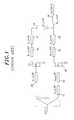
- the microwave Doherty amplifier in FIG. 1uses quarter wave transformers 31 to 39 for an output matching of a carrier amplifier 10 and a peaking amplifier 20 . In this output matching system, only a resistive matching is possible.
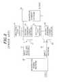
- a microwave Doherty amplifierusing another conventional output matching system.
- Shunt reactive load impedances 41 and 42are connected to an output section of the carrier amplifier 10 and the peaking amplifier 20 , respectively.
- a microwave Doherty network 50is coupled to the output sections of the carrier amplifier 10 and the peaking amplifier 20 .
- this conventional output matching systemalso has a drawback in that an output matching may not be obtained for both real and imaginary parts and the shunt reactive load impedances 41 and 42 may deteriorate the efficiency of the Doherty amplifier.
- an object of the present inventionto provide a full output matching apparatus of a Doherty amplifier which uses a characteristic impedance line added after an output matching of a microwave Doherty amplifier as a phase tuning component such that a matching state can be maintained without being changed at a high power level but can be adjusted depending on a phase variation at a low power level to obtain efficiency enhancements and optimum linearity.
- a microwave Doherty amplifierfor inducing a Doherty operation, wherein quarter wave transformers are connected to a final output of a carrier amplifier and a peaking amplifier coupled in parallel to each other, the Doherty amplifier comprising: a load matching circuit connected to output terminals of the carrier amplifier and the peaking amplifier so as to obtain a microwave output matching; and a phase tuning component located behind the load matching circuit.
- FIG. 1is a block diagram of a microwave Doherty amplifier using a conventional output matching apparatus
- FIG. 2depicts a block diagram of a microwave Doherty amplifier using another conventional output matching apparatus
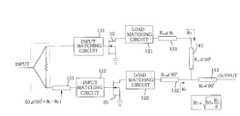
- FIG. 3sets forth a block diagram of a microwave Doherty amplifier using an output matching apparatus in accordance with the present invention
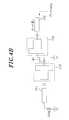
- FIGS. 4A and 4Boffer detailed circuit diagrams of the output matching apparatus in accordance with the present invention.
- FIGS. 5A and 5Bdescribe variations of a load impedance and an output impedance when a phase of a phase tuning component inserted into the output matching apparatus in FIG. 4 changes from 0° to 180°;
- FIGS. 6A and 6Bprovide experimental data of a microwave Doherty amplifier using the output matching apparatus in accordance with the present invention.
- FIG. 3there is provided a microwave Doherty amplifier using an output matching apparatus in accordance with the present invention.
- the output matching apparatusincludes a carrier amplifier 10 , a peaking amplifier 20 , input matching circuits 111 and 112 , a load matching circuit 121 for the carrier amplifier 10 , a load matching circuit 122 for the peaking amplifier 20 , an impedance line 131 having an angle of ⁇ c and an impedance line 132 having an angle of ⁇ p .
- the input matching circuits 111 and 112are disposed in front of the carrier amplifier 10 and the peaking amplifier 20 , respectively.
- the load matching circuits 121 and 122are connected to an output section of the carrier amplifier 10 and the peaking amplifier 20 , respectively, such that a characteristic impedance becomes an arbitrary impedance R 0 .
- the impedance lines 131 and 132are positioned behind the load matching circuits 121 and 122 , respectively.
- Quarter wave transformers 141 and 142are positioned behind the impedance lines 131 and 132 , respectively, to cause a Doherty operation.
- an impedance line 151 with an angle 90°+ ⁇ c ⁇ pis additionally inserted in front of the input matching circuit 112 of the peaking amplifier 20 .
- FIGS. 4A and 4Bare circuit diagrams for describing a method for calculating ⁇ c of the impedance line 131 and ⁇ p of the impedance line 132 , respectively.
- an output resistance R OUT and an output capacitor C OUTare connected to each other by a shunt function together as an equivalent circuit (A in FIG. 4A) of an output impedance Z OUT,Carrier of the carrier amplifier 10 .
- the load resistance R Lis calculated from an I/V relationship of the transistor 10 and the imaginary part X L is determined to be an imaginary part of a complex conjugate of the output impedance Z OUT,Carrier .
- the compensated load impedance looking towards the load including the capacitor C OUTcomes to have a real value for the capacitor C OUT and the final load impedance R 0 . Since the final load impedance of the carrier amplifier 10 becomes R 0 at a high power level, the load impedance Z LC,R 0 compensated by a phase tuning component having the characteristic impedance of R 0 is not changed.
- a compensated load impedance Z LC,2R 0 at this timeis found to form a circle centering around a compensated load impedance Z LC,R 0 at a high power level depending on phase variations of a phase tuning component ⁇ c .
- FIG. 5Adescribes characteristics of the load impedance described above.
- the phase tuning component ⁇ cis determined to be an angle that allows the compensated load impedance Z LC,2R 0 to be a real maximum value.
- the compensated load impedanceis found to be a maximum value close to a real number.
- a final output impedance of the peaking amplifier 20forms a large circle depending on phase variations of the phase tuning component ⁇ p at the very low power level. Since the output impedance Z O,peaking at the very low power level should be opened, it is preferable that ⁇ p has a value that allows the output impedance Z O,peaking to have a genuine resistive component of a real number.
- ⁇ phas a value that allows the output impedance Z O,peaking to have a genuine resistive component of a real number.
- FIG. 5Bit is found that the final output impedance of the peaking amplifier 20 has a very large real value when ⁇ p has an angel ranging from 40° to 60°.
- the Doherty amplifieremployed a class AB amplifier as the carrier amplifier and a class C amplifier as the peaking amplifier.
- FIG. 6Athere is provided a table that shows power-added efficiencies (PAE) of the microwave Doherty amplifier of the present invention and the conventional class AB amplifier when a CW signal is inputted thereto. It will be apparent to those skilled in the art that the Doherty amplifier using the output matching apparatus of the present invention exhibits a still higher efficiency.
- FIG. 1power-added efficiencies
- the Doherty amplifier in accordance with the present inventionshows an adjacent channel leakage ratio (ACLR) of about 5.7 dB lower than that of the AB amplifier at a 885 kHz offset point at an output power of about 32 dBm.
- ACLRadjacent channel leakage ratio
- an impedance linesuch as a characteristic impedance is added and used as a phase tuning component after a microwave output matching performance of a microwave Doherty amplifier.
- a matching statecan be maintained without being changed at a high power level but can be adjusted at a low power level depending on phase variations to attain efficiency enhancements and optimum linearity.
- the output matching apparatus of the present inventionparticularly exhibits highly reliable efficiency and highly improved linearity when it is applied to a power amplifier for a base station in a conventional or next-generation mobile communications system.
Landscapes
- Engineering & Computer Science (AREA)
- Power Engineering (AREA)
- Microwave Amplifiers (AREA)
- Amplifiers (AREA)
Abstract
Description
Claims (8)
Applications Claiming Priority (2)
| Application Number | Priority Date | Filing Date | Title |
|---|---|---|---|
| KR1020010014516AKR100546491B1 (en) | 2001-03-21 | 2001-03-21 | Output Matching Device for Microwave Doherty Amplifiers |
| KR2001-14516 | 2001-03-21 |
Publications (2)
| Publication Number | Publication Date |
|---|---|
| US20020135425A1 US20020135425A1 (en) | 2002-09-26 |
| US6617929B2true US6617929B2 (en) | 2003-09-09 |
Family
ID=19707188
Family Applications (1)
| Application Number | Title | Priority Date | Filing Date |
|---|---|---|---|
| US10/076,636Expired - LifetimeUS6617929B2 (en) | 2001-03-21 | 2002-02-19 | Full output matching apparatus of a microwave doherty amplifier |
Country Status (2)
| Country | Link |
|---|---|
| US (1) | US6617929B2 (en) |
| KR (1) | KR100546491B1 (en) |
Cited By (27)
| Publication number | Priority date | Publication date | Assignee | Title |
|---|---|---|---|---|
| US20030137346A1 (en)* | 2000-07-07 | 2003-07-24 | Richard Hellberg | Transmitter including a composite amplifier |
| US20040056723A1 (en)* | 2002-09-24 | 2004-03-25 | Mitsubishi Denki Kabushiki Kaisha | High-frequency power amplifier |
| WO2004027982A3 (en)* | 2002-09-20 | 2004-07-15 | Triquint Semiconductor Inc | Linear power amplifier with multiple output power levels |
| US20040183593A1 (en)* | 2002-02-01 | 2004-09-23 | Youngwoo Kwon | Power amplification apparatus of portable terminal |
| WO2005031967A1 (en)* | 2003-09-30 | 2005-04-07 | Kwangwoon University Research Institute For Industrial Cooperation | Doherty power amplifying apparatus |
| US20050227644A1 (en)* | 2004-04-09 | 2005-10-13 | Nikolai Maslennikov | Constant gain nonlinear envelope tracking high efficiency linear amplifier |
| US20050231286A1 (en)* | 2004-04-14 | 2005-10-20 | Mitsubishi Denki Kabushiki Kaisha | Power amplifier |
| US20050242875A1 (en)* | 2004-03-19 | 2005-11-03 | Mark Gurvich | High efficiency linear amplifier employing dynamically controlled back off |
| US20060044060A1 (en)* | 2004-08-26 | 2006-03-02 | Nec Corporation | Circuit for parallel operation of Doherty amplifiers |
| US20060087371A1 (en)* | 2004-10-26 | 2006-04-27 | Andrew Corporation | High efficiency amplifier |
| US20070135065A1 (en)* | 2005-12-13 | 2007-06-14 | Andrew Corporation | Predistortion system and amplifier for addressing group delay modulation |
| US20070176677A1 (en)* | 2006-01-18 | 2007-08-02 | Triquint Semiconductor, Inc. | Switched distributed power amplifier |
| US20070285158A1 (en)* | 2006-05-02 | 2007-12-13 | Akira Seino | Amplifier unit and method of detecting failure in the same |
| US20080007331A1 (en)* | 2006-06-23 | 2008-01-10 | Ntt Docomo, Inc | Multiband doherty amplifier |
| US20090051438A1 (en)* | 2005-05-23 | 2009-02-26 | Yoichi Okubo | Amplifying system |
| US20090167438A1 (en)* | 2007-12-28 | 2009-07-02 | Sungkyunkwan University Foundation For Corporate Collaboration | Harmonic tuned doherty amplifier |
| US20090206926A1 (en)* | 2005-08-01 | 2009-08-20 | Mitsubishi Electric Corporation | High Efficiency Amplifier |
| US20090289719A1 (en)* | 2002-09-17 | 2009-11-26 | Adrianus Van Bezooijen | Preserving Linearity of a RF Power Amplifier |
| US20100001802A1 (en)* | 2005-05-20 | 2010-01-07 | Nxp B.V. | Integrated doherty type amplifier arrangement with high power efficiency |
| US20100141338A1 (en)* | 2007-08-06 | 2010-06-10 | Wipam, Inc. | Broadband power amplifier |
| US20110025412A1 (en)* | 2008-04-24 | 2011-02-03 | Koji Matsunaga | Amplifier |
| US20140159808A1 (en)* | 2012-12-11 | 2014-06-12 | Alcatel-Lucent Canada Inc. | Design and Analysis of Doherty Amplifiers |
| US9071202B2 (en) | 2013-10-18 | 2015-06-30 | Alcatel Lucent | Doherty amplifier with peak branch RF conditioning |
| US9374041B2 (en) | 2011-12-15 | 2016-06-21 | Telefonaktiebolaget Lm Ericsson (Publ) | Doherty power amplification apparatus and method |
| CN107026617A (en)* | 2015-11-06 | 2017-08-08 | 英飞凌科技股份有限公司 | Use next stage input impedance and the out-phase power amplifier demultiplexer biased more |
| US9966903B1 (en) | 2016-12-30 | 2018-05-08 | Nxp Usa, Inc. | Doherty architecture for wideband power amplifier design |
| US10270406B2 (en)* | 2016-08-04 | 2019-04-23 | Fujitsu Limited | Power amplifier, semiconductor integrated circuit, and method of controlling the power amplifier |
Families Citing this family (19)
| Publication number | Priority date | Publication date | Assignee | Title |
|---|---|---|---|---|
| US6791417B2 (en)* | 2002-01-28 | 2004-09-14 | Cree Microwave, Inc. | N-way RF power amplifier circuit with increased back-off capability and power added efficiency using selected phase lengths and output impedances |
| US6894561B2 (en)* | 2002-09-20 | 2005-05-17 | Triquint Semiconductor, Inc. | Efficient power control of a power amplifier by periphery switching |
| WO2004027983A2 (en) | 2002-09-20 | 2004-04-01 | Triquint Semiconductor, Inc. | Saturated power amplifier with selectable and variable output power levels |
| NL1027745C1 (en)* | 2004-12-14 | 2006-06-16 | Bosma Beheersmij B V H O D N M | Low-loss, asymmetrical combinator for phase difference systems and adaptive RF amplifier comprising an asymmetrical combiner. |
| KR100749870B1 (en)* | 2006-06-07 | 2007-08-17 | (주) 와이팜 | Doherty power amplifier |
| TWI346449B (en)* | 2007-08-16 | 2011-08-01 | Ind Tech Res Inst | Power amplifier circuit for multi-frequencies and multi-modes and method for operating the same |
| KR101021471B1 (en)* | 2008-12-08 | 2011-03-15 | 광운대학교 산학협력단 | Dynamic Doherty Power Amplifiers |
| KR101091969B1 (en)* | 2009-06-01 | 2011-12-09 | 포항공과대학교 산학협력단 | Power amplifier apparatus |
| EP2323253A1 (en)* | 2009-10-26 | 2011-05-18 | Alcatel Lucent | Doherty power amplifiers |
| CN102130657A (en)* | 2010-09-14 | 2011-07-20 | 华为技术有限公司 | A power amplifier, asymmetric Daherdy power amplification equipment and base station |
| CN102265506B (en)* | 2011-05-27 | 2013-08-28 | 华为技术有限公司 | Taoherty Doherty circuit, multi-channel Taoherty Doherty circuit and base station equipment |
| US9787253B2 (en) | 2013-09-12 | 2017-10-10 | Nec Corporation | Doherty amplifier and transmission apparatus |
| US9503028B2 (en)* | 2015-01-30 | 2016-11-22 | Mitsubishi Electric Research Laboratories, Inc. | Three-way sequential power amplifier system for wideband RF signal |
| JP6316506B2 (en)* | 2015-06-15 | 2018-04-25 | 株式会社日立国際電気 | Power amplifier and wireless transmitter |
| CN106571781B (en) | 2015-10-08 | 2020-09-25 | 大唐移动通信设备有限公司 | Doherty power amplifying circuit |
| KR102585866B1 (en)* | 2016-06-21 | 2023-10-06 | 삼성전기주식회사 | Resonance apparatus and apparatus for transmiting power wirelessly using the same |
| CN107493076A (en)* | 2017-06-21 | 2017-12-19 | 中国电子科技集团公司第五十五研究所 | Improve the Doherty amplifiers of phase equalization using reassembling type delay part |
| US10491165B2 (en)* | 2018-03-12 | 2019-11-26 | Psemi Corporation | Doherty amplifier with adjustable alpha factor |
| US11616476B2 (en)* | 2020-10-19 | 2023-03-28 | City University Of Hong Kong | Power amplifier circuit |
Citations (5)
| Publication number | Priority date | Publication date | Assignee | Title |
|---|---|---|---|---|
| US5568086A (en)* | 1995-05-25 | 1996-10-22 | Motorola, Inc. | Linear power amplifier for high efficiency multi-carrier performance |
| US5786727A (en)* | 1996-10-15 | 1998-07-28 | Motorola, Inc. | Multi-stage high efficiency linear power amplifier and method therefor |
| US6356149B1 (en)* | 2000-04-10 | 2002-03-12 | Motorola, Inc. | Tunable inductor circuit, phase tuning circuit and applications thereof |
| US6396341B1 (en)* | 2000-12-29 | 2002-05-28 | Ericsson Inc. | Class E Doherty amplifier topology for high efficiency signal transmitters |
| US6472934B1 (en)* | 2000-12-29 | 2002-10-29 | Ericsson Inc. | Triple class E Doherty amplifier topology for high efficiency signal transmitters |
- 2001
- 2001-03-21KRKR1020010014516Apatent/KR100546491B1/ennot_activeExpired - Lifetime
- 2002
- 2002-02-19USUS10/076,636patent/US6617929B2/ennot_activeExpired - Lifetime
Patent Citations (5)
| Publication number | Priority date | Publication date | Assignee | Title |
|---|---|---|---|---|
| US5568086A (en)* | 1995-05-25 | 1996-10-22 | Motorola, Inc. | Linear power amplifier for high efficiency multi-carrier performance |
| US5786727A (en)* | 1996-10-15 | 1998-07-28 | Motorola, Inc. | Multi-stage high efficiency linear power amplifier and method therefor |
| US6356149B1 (en)* | 2000-04-10 | 2002-03-12 | Motorola, Inc. | Tunable inductor circuit, phase tuning circuit and applications thereof |
| US6396341B1 (en)* | 2000-12-29 | 2002-05-28 | Ericsson Inc. | Class E Doherty amplifier topology for high efficiency signal transmitters |
| US6472934B1 (en)* | 2000-12-29 | 2002-10-29 | Ericsson Inc. | Triple class E Doherty amplifier topology for high efficiency signal transmitters |
Cited By (51)
| Publication number | Priority date | Publication date | Assignee | Title |
|---|---|---|---|---|
| US6940349B2 (en)* | 2000-07-07 | 2005-09-06 | Telefonaktiebolaget Lm Ericsson (Publ) | Transmitter including a composite amplifier |
| US20030137346A1 (en)* | 2000-07-07 | 2003-07-24 | Richard Hellberg | Transmitter including a composite amplifier |
| US20040183593A1 (en)* | 2002-02-01 | 2004-09-23 | Youngwoo Kwon | Power amplification apparatus of portable terminal |
| US7304537B2 (en) | 2002-02-01 | 2007-12-04 | Avago Technologies Korea Co., Ltd | Power amplification apparatus of a portable terminal |
| US7345535B2 (en)* | 2002-02-01 | 2008-03-18 | Avago Technologies Korea Co. Ltd. | Power amplification apparatus of portable terminal |
| US20070057722A1 (en)* | 2002-02-01 | 2007-03-15 | Youngwoo Kwon | Power amplification apparatus of a portable terminal |
| US20090289719A1 (en)* | 2002-09-17 | 2009-11-26 | Adrianus Van Bezooijen | Preserving Linearity of a RF Power Amplifier |
| WO2004027982A3 (en)* | 2002-09-20 | 2004-07-15 | Triquint Semiconductor Inc | Linear power amplifier with multiple output power levels |
| US7345537B2 (en)* | 2002-09-20 | 2008-03-18 | Triquint Semiconductor, Inc. | Linear power amplifier with multiple output power levels |
| US6861907B2 (en)* | 2002-09-24 | 2005-03-01 | Mitsubishi Denki Kabushiki Kaisha | Power amplifier |
| US20040056723A1 (en)* | 2002-09-24 | 2004-03-25 | Mitsubishi Denki Kabushiki Kaisha | High-frequency power amplifier |
| WO2005031967A1 (en)* | 2003-09-30 | 2005-04-07 | Kwangwoon University Research Institute For Industrial Cooperation | Doherty power amplifying apparatus |
| US7339426B2 (en) | 2004-03-19 | 2008-03-04 | Powerwave Technologies, Inc. | High efficiency linear amplifier employing dynamically controlled back off |
| US20050242875A1 (en)* | 2004-03-19 | 2005-11-03 | Mark Gurvich | High efficiency linear amplifier employing dynamically controlled back off |
| US7440733B2 (en) | 2004-04-09 | 2008-10-21 | Powerwave Technologies, Inc. | Constant gain nonlinear envelope tracking high efficiency linear amplifier |
| US20050227644A1 (en)* | 2004-04-09 | 2005-10-13 | Nikolai Maslennikov | Constant gain nonlinear envelope tracking high efficiency linear amplifier |
| US7193472B2 (en)* | 2004-04-14 | 2007-03-20 | Mitsubishi Denki Kabushiki Kaisha | Power amplifier |
| US20050231286A1 (en)* | 2004-04-14 | 2005-10-20 | Mitsubishi Denki Kabushiki Kaisha | Power amplifier |
| US20060044060A1 (en)* | 2004-08-26 | 2006-03-02 | Nec Corporation | Circuit for parallel operation of Doherty amplifiers |
| US7262656B2 (en)* | 2004-08-26 | 2007-08-28 | Nec Corporation | Circuit for parallel operation of Doherty amplifiers |
| US20060087371A1 (en)* | 2004-10-26 | 2006-04-27 | Andrew Corporation | High efficiency amplifier |
| US7148746B2 (en) | 2004-10-26 | 2006-12-12 | Andrew Corporation | High efficiency amplifier |
| US20100001802A1 (en)* | 2005-05-20 | 2010-01-07 | Nxp B.V. | Integrated doherty type amplifier arrangement with high power efficiency |
| US20090051438A1 (en)* | 2005-05-23 | 2009-02-26 | Yoichi Okubo | Amplifying system |
| US7714648B2 (en)* | 2005-05-23 | 2010-05-11 | Hitachi Kokusai Electric Inc. | Amplifying system |
| US7649412B2 (en)* | 2005-08-01 | 2010-01-19 | Mitsubishi Electric Corporation | High efficiency amplifier |
| US20090206926A1 (en)* | 2005-08-01 | 2009-08-20 | Mitsubishi Electric Corporation | High Efficiency Amplifier |
| US20070135065A1 (en)* | 2005-12-13 | 2007-06-14 | Andrew Corporation | Predistortion system and amplifier for addressing group delay modulation |
| US7831221B2 (en) | 2005-12-13 | 2010-11-09 | Andrew Llc | Predistortion system and amplifier for addressing group delay modulation |
| US7382194B2 (en) | 2006-01-18 | 2008-06-03 | Triquint Semiconductor, Inc. | Switched distributed power amplifier |
| US20070176677A1 (en)* | 2006-01-18 | 2007-08-02 | Triquint Semiconductor, Inc. | Switched distributed power amplifier |
| US7456687B2 (en)* | 2006-05-02 | 2008-11-25 | Fujitsu Limited | Amplifier unit and method of detecting failure in the same |
| US20070285158A1 (en)* | 2006-05-02 | 2007-12-13 | Akira Seino | Amplifier unit and method of detecting failure in the same |
| US20080007331A1 (en)* | 2006-06-23 | 2008-01-10 | Ntt Docomo, Inc | Multiband doherty amplifier |
| US7602241B2 (en)* | 2006-06-23 | 2009-10-13 | Ntt Docomo, Inc. | Multiband Doherty amplifier |
| US8198938B2 (en)* | 2007-08-06 | 2012-06-12 | Wipam, Inc. | Broadband power amplifier |
| US20100141338A1 (en)* | 2007-08-06 | 2010-06-10 | Wipam, Inc. | Broadband power amplifier |
| US20090167438A1 (en)* | 2007-12-28 | 2009-07-02 | Sungkyunkwan University Foundation For Corporate Collaboration | Harmonic tuned doherty amplifier |
| US7646248B2 (en)* | 2007-12-28 | 2010-01-12 | Sungkyunwan University Foundation for Corporate Collaboration | Harmonic tuned doherty amplifier |
| US8508295B2 (en)* | 2008-04-24 | 2013-08-13 | Nec Corporation | Amplifier |
| US20110025412A1 (en)* | 2008-04-24 | 2011-02-03 | Koji Matsunaga | Amplifier |
| US9374041B2 (en) | 2011-12-15 | 2016-06-21 | Telefonaktiebolaget Lm Ericsson (Publ) | Doherty power amplification apparatus and method |
| US20140159808A1 (en)* | 2012-12-11 | 2014-06-12 | Alcatel-Lucent Canada Inc. | Design and Analysis of Doherty Amplifiers |
| US8975955B2 (en)* | 2012-12-11 | 2015-03-10 | Alcatel Lucent | Analysis of Doherty amplifiers |
| US9071202B2 (en) | 2013-10-18 | 2015-06-30 | Alcatel Lucent | Doherty amplifier with peak branch RF conditioning |
| CN107026617A (en)* | 2015-11-06 | 2017-08-08 | 英飞凌科技股份有限公司 | Use next stage input impedance and the out-phase power amplifier demultiplexer biased more |
| US9787259B2 (en)* | 2015-11-06 | 2017-10-10 | Infineon Technologies Ag | Outphasing power amplifier signal splitter using next stage input impedance and multiple biasing |
| CN107026617B (en)* | 2015-11-06 | 2021-04-13 | 英飞凌科技股份有限公司 | Out-of-phase power amplifier demultiplexer using next stage input impedance and multi-bias |
| US10270406B2 (en)* | 2016-08-04 | 2019-04-23 | Fujitsu Limited | Power amplifier, semiconductor integrated circuit, and method of controlling the power amplifier |
| US9966903B1 (en) | 2016-12-30 | 2018-05-08 | Nxp Usa, Inc. | Doherty architecture for wideband power amplifier design |
| US9973150B1 (en)* | 2016-12-30 | 2018-05-15 | Nxp Usa, Inc. | Doherty architecture for wideband power amplifier design |
Also Published As
| Publication number | Publication date |
|---|---|
| KR20020074630A (en) | 2002-10-04 |
| KR100546491B1 (en) | 2006-01-26 |
| US20020135425A1 (en) | 2002-09-26 |
Similar Documents
| Publication | Publication Date | Title |
|---|---|---|
| US6617929B2 (en) | Full output matching apparatus of a microwave doherty amplifier | |
| US7646248B2 (en) | Harmonic tuned doherty amplifier | |
| US6320462B1 (en) | Amplifier circuit | |
| Van Der Heijden et al. | A 19W high-efficiency wide-band CMOS-GaN class-E Chireix RF outphasing power amplifier | |
| KR100450744B1 (en) | Doherty amplifier | |
| US7940120B2 (en) | Power amplifier linearization using RF feedback | |
| US20040113698A1 (en) | Signal amplifier using a doherty amplifier | |
| US20040119533A1 (en) | High linearity doherty communication amplifier with bias control | |
| US8811531B2 (en) | Quadrature lattice matching network | |
| US10666207B1 (en) | Broadband harmonic matching network using low-pass type broadband matching | |
| KR20060077818A (en) | Power amplification device using asymmetric power drive | |
| JP2005223849A (en) | Distortion compensation apparatus and power amplifier with distortion compensation function | |
| CN107332519A (en) | A kind of broadband Doherty power amplifier and its implementation that combiner is exported based on modified | |
| JP2008125044A (en) | amplifier | |
| WO2005043747A2 (en) | High linearity doherty communication amplifier with bias control | |
| Tseng et al. | Improvement of return loss bandwidth of balanced amplifier using metamaterial-based quadrature power splitters | |
| KR100394328B1 (en) | Reflection type low phase shift attenuator | |
| Choi et al. | Two-stage Doherty power amplifier using broadband interstage matching network | |
| US7102464B1 (en) | Switched transformer for adjusting power amplifier loading | |
| Sah et al. | Prototype for an optimized drive signal control system for a 2.5 GHz Doherty power amplifier | |
| US12308797B2 (en) | Filter combiner for a Doherty amplifier, and a Doherty amplifier | |
| Kumar et al. | A Novel Analog Predistortion Technique for LTE Communication Systems | |
| Chen et al. | Two-Way Current Combining Power Amplifier with Multi-Stage Adaptive Bias Control | |
| Sim et al. | A 100Watt ultra-broadband power amplifier using silicon LDMOSFETs | |
| Das et al. | K Band High Power Broadband AlGaN/GaN HEMT Balanced Power Amplifier for Satellite Transponder |
Legal Events
| Date | Code | Title | Description |
|---|---|---|---|
| AS | Assignment | Owner name:POSTECH FOUNDATION, KOREA, REPUBLIC OF Free format text:ASSIGNMENT OF ASSIGNORS INTEREST;ASSIGNORS:KIM, BUMMAN;YANG, YOUNGOO;YI, JAEHYOK;AND OTHERS;REEL/FRAME:012608/0109 Effective date:20020129 | |
| STCF | Information on status: patent grant | Free format text:PATENTED CASE | |
| FEPP | Fee payment procedure | Free format text:PAYOR NUMBER ASSIGNED (ORIGINAL EVENT CODE: ASPN); ENTITY STATUS OF PATENT OWNER: LARGE ENTITY | |
| FPAY | Fee payment | Year of fee payment:4 | |
| FEPP | Fee payment procedure | Free format text:PAT HOLDER NO LONGER CLAIMS SMALL ENTITY STATUS, ENTITY STATUS SET TO UNDISCOUNTED (ORIGINAL EVENT CODE: STOL); ENTITY STATUS OF PATENT OWNER: LARGE ENTITY | |
| FEPP | Fee payment procedure | Free format text:PAYER NUMBER DE-ASSIGNED (ORIGINAL EVENT CODE: RMPN); ENTITY STATUS OF PATENT OWNER: LARGE ENTITY | |
| FEPP | Fee payment procedure | Free format text:PAYOR NUMBER ASSIGNED (ORIGINAL EVENT CODE: ASPN); ENTITY STATUS OF PATENT OWNER: LARGE ENTITY | |
| FEPP | Fee payment procedure | Free format text:PAYER NUMBER DE-ASSIGNED (ORIGINAL EVENT CODE: RMPN); ENTITY STATUS OF PATENT OWNER: LARGE ENTITY Free format text:PAYOR NUMBER ASSIGNED (ORIGINAL EVENT CODE: ASPN); ENTITY STATUS OF PATENT OWNER: LARGE ENTITY | |
| AS | Assignment | Owner name:SAMSUNG ELECTRONICS CO., LTD., KOREA, REPUBLIC OF Free format text:ASSIGNMENT OF ASSIGNORS INTEREST;ASSIGNOR:POSTECH FOUNDATION;REEL/FRAME:024294/0832 Effective date:20100226 | |
| FPAY | Fee payment | Year of fee payment:8 | |
| FPAY | Fee payment | Year of fee payment:12 |