US6617820B2 - Auxiliary power conversion by phase-controlled rectification - Google Patents
Auxiliary power conversion by phase-controlled rectificationDownload PDFInfo
- Publication number
- US6617820B2 US6617820B2US09/947,294US94729401AUS6617820B2US 6617820 B2US6617820 B2US 6617820B2US 94729401 AUS94729401 AUS 94729401AUS 6617820 B2US6617820 B2US 6617820B2
- Authority
- US
- United States
- Prior art keywords
- traction motor
- electric traction
- providing
- voltage
- inverter
- Prior art date
- Legal status (The legal status is an assumption and is not a legal conclusion. Google has not performed a legal analysis and makes no representation as to the accuracy of the status listed.)
- Expired - Fee Related, expires
Links
- 238000006243chemical reactionMethods0.000titledescription2
- 238000004804windingMethods0.000claimsabstractdescription55
- 238000000034methodMethods0.000claimsabstractdescription11
- 230000004044responseEffects0.000claimsdescription12
- 230000006698inductionEffects0.000claimsdescription2
- 230000001143conditioned effectEffects0.000claims1
- 230000000694effectsEffects0.000claims1
- 238000010079rubber tappingMethods0.000abstract1
- 238000005516engineering processMethods0.000description4
- 230000009977dual effectEffects0.000description3
- 239000000446fuelSubstances0.000description3
- 238000006842Henry reactionMethods0.000description2
- XUIMIQQOPSSXEZ-UHFFFAOYSA-NSiliconChemical compound[Si]XUIMIQQOPSSXEZ-UHFFFAOYSA-N0.000description1
- 238000013459approachMethods0.000description1
- 230000008901benefitEffects0.000description1
- 239000003990capacitorSubstances0.000description1
- 230000007423decreaseEffects0.000description1
- 230000005669field effectEffects0.000description1
- 238000001914filtrationMethods0.000description1
- 230000006870functionEffects0.000description1
- 229910044991metal oxideInorganic materials0.000description1
- 150000004706metal oxidesChemical class0.000description1
- 230000004048modificationEffects0.000description1
- 238000012986modificationMethods0.000description1
- 230000006855networkingEffects0.000description1
- 230000007935neutral effectEffects0.000description1
- 238000012545processingMethods0.000description1
- 239000004065semiconductorSubstances0.000description1
- 229910052710siliconInorganic materials0.000description1
- 239000010703siliconSubstances0.000description1
- 230000001360synchronised effectEffects0.000description1
Images

Classifications
- B—PERFORMING OPERATIONS; TRANSPORTING
- B60—VEHICLES IN GENERAL
- B60L—PROPULSION OF ELECTRICALLY-PROPELLED VEHICLES; SUPPLYING ELECTRIC POWER FOR AUXILIARY EQUIPMENT OF ELECTRICALLY-PROPELLED VEHICLES; ELECTRODYNAMIC BRAKE SYSTEMS FOR VEHICLES IN GENERAL; MAGNETIC SUSPENSION OR LEVITATION FOR VEHICLES; MONITORING OPERATING VARIABLES OF ELECTRICALLY-PROPELLED VEHICLES; ELECTRIC SAFETY DEVICES FOR ELECTRICALLY-PROPELLED VEHICLES
- B60L1/00—Supplying electric power to auxiliary equipment of vehicles
- B60L1/003—Supplying electric power to auxiliary equipment of vehicles to auxiliary motors, e.g. for pumps, compressors
- B—PERFORMING OPERATIONS; TRANSPORTING
- B60—VEHICLES IN GENERAL
- B60L—PROPULSION OF ELECTRICALLY-PROPELLED VEHICLES; SUPPLYING ELECTRIC POWER FOR AUXILIARY EQUIPMENT OF ELECTRICALLY-PROPELLED VEHICLES; ELECTRODYNAMIC BRAKE SYSTEMS FOR VEHICLES IN GENERAL; MAGNETIC SUSPENSION OR LEVITATION FOR VEHICLES; MONITORING OPERATING VARIABLES OF ELECTRICALLY-PROPELLED VEHICLES; ELECTRIC SAFETY DEVICES FOR ELECTRICALLY-PROPELLED VEHICLES
- B60L15/00—Methods, circuits, or devices for controlling the traction-motor speed of electrically-propelled vehicles
- B60L15/007—Physical arrangements or structures of drive train converters specially adapted for the propulsion motors of electric vehicles
- B—PERFORMING OPERATIONS; TRANSPORTING
- B60—VEHICLES IN GENERAL
- B60L—PROPULSION OF ELECTRICALLY-PROPELLED VEHICLES; SUPPLYING ELECTRIC POWER FOR AUXILIARY EQUIPMENT OF ELECTRICALLY-PROPELLED VEHICLES; ELECTRODYNAMIC BRAKE SYSTEMS FOR VEHICLES IN GENERAL; MAGNETIC SUSPENSION OR LEVITATION FOR VEHICLES; MONITORING OPERATING VARIABLES OF ELECTRICALLY-PROPELLED VEHICLES; ELECTRIC SAFETY DEVICES FOR ELECTRICALLY-PROPELLED VEHICLES
- B60L15/00—Methods, circuits, or devices for controlling the traction-motor speed of electrically-propelled vehicles
- B60L15/20—Methods, circuits, or devices for controlling the traction-motor speed of electrically-propelled vehicles for control of the vehicle or its driving motor to achieve a desired performance, e.g. speed, torque, programmed variation of speed
- B—PERFORMING OPERATIONS; TRANSPORTING
- B60—VEHICLES IN GENERAL
- B60L—PROPULSION OF ELECTRICALLY-PROPELLED VEHICLES; SUPPLYING ELECTRIC POWER FOR AUXILIARY EQUIPMENT OF ELECTRICALLY-PROPELLED VEHICLES; ELECTRODYNAMIC BRAKE SYSTEMS FOR VEHICLES IN GENERAL; MAGNETIC SUSPENSION OR LEVITATION FOR VEHICLES; MONITORING OPERATING VARIABLES OF ELECTRICALLY-PROPELLED VEHICLES; ELECTRIC SAFETY DEVICES FOR ELECTRICALLY-PROPELLED VEHICLES
- B60L50/00—Electric propulsion with power supplied within the vehicle
- B60L50/50—Electric propulsion with power supplied within the vehicle using propulsion power supplied by batteries or fuel cells
- B60L50/51—Electric propulsion with power supplied within the vehicle using propulsion power supplied by batteries or fuel cells characterised by AC-motors
- B—PERFORMING OPERATIONS; TRANSPORTING
- B60—VEHICLES IN GENERAL
- B60L—PROPULSION OF ELECTRICALLY-PROPELLED VEHICLES; SUPPLYING ELECTRIC POWER FOR AUXILIARY EQUIPMENT OF ELECTRICALLY-PROPELLED VEHICLES; ELECTRODYNAMIC BRAKE SYSTEMS FOR VEHICLES IN GENERAL; MAGNETIC SUSPENSION OR LEVITATION FOR VEHICLES; MONITORING OPERATING VARIABLES OF ELECTRICALLY-PROPELLED VEHICLES; ELECTRIC SAFETY DEVICES FOR ELECTRICALLY-PROPELLED VEHICLES
- B60L58/00—Methods or circuit arrangements for monitoring or controlling batteries or fuel cells, specially adapted for electric vehicles
- B60L58/40—Methods or circuit arrangements for monitoring or controlling batteries or fuel cells, specially adapted for electric vehicles for controlling a combination of batteries and fuel cells
- B—PERFORMING OPERATIONS; TRANSPORTING
- B60—VEHICLES IN GENERAL
- B60L—PROPULSION OF ELECTRICALLY-PROPELLED VEHICLES; SUPPLYING ELECTRIC POWER FOR AUXILIARY EQUIPMENT OF ELECTRICALLY-PROPELLED VEHICLES; ELECTRODYNAMIC BRAKE SYSTEMS FOR VEHICLES IN GENERAL; MAGNETIC SUSPENSION OR LEVITATION FOR VEHICLES; MONITORING OPERATING VARIABLES OF ELECTRICALLY-PROPELLED VEHICLES; ELECTRIC SAFETY DEVICES FOR ELECTRICALLY-PROPELLED VEHICLES
- B60L2220/00—Electrical machine types; Structures or applications thereof
- B60L2220/10—Electrical machine types
- B60L2220/18—Reluctance machines
- B—PERFORMING OPERATIONS; TRANSPORTING
- B60—VEHICLES IN GENERAL
- B60L—PROPULSION OF ELECTRICALLY-PROPELLED VEHICLES; SUPPLYING ELECTRIC POWER FOR AUXILIARY EQUIPMENT OF ELECTRICALLY-PROPELLED VEHICLES; ELECTRODYNAMIC BRAKE SYSTEMS FOR VEHICLES IN GENERAL; MAGNETIC SUSPENSION OR LEVITATION FOR VEHICLES; MONITORING OPERATING VARIABLES OF ELECTRICALLY-PROPELLED VEHICLES; ELECTRIC SAFETY DEVICES FOR ELECTRICALLY-PROPELLED VEHICLES
- B60L2220/00—Electrical machine types; Structures or applications thereof
- B60L2220/50—Structural details of electrical machines
- B60L2220/54—Windings for different functions
- B—PERFORMING OPERATIONS; TRANSPORTING
- B60—VEHICLES IN GENERAL
- B60L—PROPULSION OF ELECTRICALLY-PROPELLED VEHICLES; SUPPLYING ELECTRIC POWER FOR AUXILIARY EQUIPMENT OF ELECTRICALLY-PROPELLED VEHICLES; ELECTRODYNAMIC BRAKE SYSTEMS FOR VEHICLES IN GENERAL; MAGNETIC SUSPENSION OR LEVITATION FOR VEHICLES; MONITORING OPERATING VARIABLES OF ELECTRICALLY-PROPELLED VEHICLES; ELECTRIC SAFETY DEVICES FOR ELECTRICALLY-PROPELLED VEHICLES
- B60L2220/00—Electrical machine types; Structures or applications thereof
- B60L2220/50—Structural details of electrical machines
- B60L2220/58—Structural details of electrical machines with more than three phases
- B—PERFORMING OPERATIONS; TRANSPORTING
- B60—VEHICLES IN GENERAL
- B60L—PROPULSION OF ELECTRICALLY-PROPELLED VEHICLES; SUPPLYING ELECTRIC POWER FOR AUXILIARY EQUIPMENT OF ELECTRICALLY-PROPELLED VEHICLES; ELECTRODYNAMIC BRAKE SYSTEMS FOR VEHICLES IN GENERAL; MAGNETIC SUSPENSION OR LEVITATION FOR VEHICLES; MONITORING OPERATING VARIABLES OF ELECTRICALLY-PROPELLED VEHICLES; ELECTRIC SAFETY DEVICES FOR ELECTRICALLY-PROPELLED VEHICLES
- B60L2240/00—Control parameters of input or output; Target parameters
- B60L2240/40—Drive Train control parameters
- B60L2240/42—Drive Train control parameters related to electric machines
- B60L2240/421—Speed
- B—PERFORMING OPERATIONS; TRANSPORTING
- B60—VEHICLES IN GENERAL
- B60L—PROPULSION OF ELECTRICALLY-PROPELLED VEHICLES; SUPPLYING ELECTRIC POWER FOR AUXILIARY EQUIPMENT OF ELECTRICALLY-PROPELLED VEHICLES; ELECTRODYNAMIC BRAKE SYSTEMS FOR VEHICLES IN GENERAL; MAGNETIC SUSPENSION OR LEVITATION FOR VEHICLES; MONITORING OPERATING VARIABLES OF ELECTRICALLY-PROPELLED VEHICLES; ELECTRIC SAFETY DEVICES FOR ELECTRICALLY-PROPELLED VEHICLES
- B60L2240/00—Control parameters of input or output; Target parameters
- B60L2240/40—Drive Train control parameters
- B60L2240/42—Drive Train control parameters related to electric machines
- B60L2240/423—Torque
- B—PERFORMING OPERATIONS; TRANSPORTING
- B60—VEHICLES IN GENERAL
- B60L—PROPULSION OF ELECTRICALLY-PROPELLED VEHICLES; SUPPLYING ELECTRIC POWER FOR AUXILIARY EQUIPMENT OF ELECTRICALLY-PROPELLED VEHICLES; ELECTRODYNAMIC BRAKE SYSTEMS FOR VEHICLES IN GENERAL; MAGNETIC SUSPENSION OR LEVITATION FOR VEHICLES; MONITORING OPERATING VARIABLES OF ELECTRICALLY-PROPELLED VEHICLES; ELECTRIC SAFETY DEVICES FOR ELECTRICALLY-PROPELLED VEHICLES
- B60L2240/00—Control parameters of input or output; Target parameters
- B60L2240/40—Drive Train control parameters
- B60L2240/42—Drive Train control parameters related to electric machines
- B60L2240/427—Voltage
- B—PERFORMING OPERATIONS; TRANSPORTING
- B60—VEHICLES IN GENERAL
- B60L—PROPULSION OF ELECTRICALLY-PROPELLED VEHICLES; SUPPLYING ELECTRIC POWER FOR AUXILIARY EQUIPMENT OF ELECTRICALLY-PROPELLED VEHICLES; ELECTRODYNAMIC BRAKE SYSTEMS FOR VEHICLES IN GENERAL; MAGNETIC SUSPENSION OR LEVITATION FOR VEHICLES; MONITORING OPERATING VARIABLES OF ELECTRICALLY-PROPELLED VEHICLES; ELECTRIC SAFETY DEVICES FOR ELECTRICALLY-PROPELLED VEHICLES
- B60L2240/00—Control parameters of input or output; Target parameters
- B60L2240/40—Drive Train control parameters
- B60L2240/42—Drive Train control parameters related to electric machines
- B60L2240/429—Current
- B—PERFORMING OPERATIONS; TRANSPORTING
- B60—VEHICLES IN GENERAL
- B60L—PROPULSION OF ELECTRICALLY-PROPELLED VEHICLES; SUPPLYING ELECTRIC POWER FOR AUXILIARY EQUIPMENT OF ELECTRICALLY-PROPELLED VEHICLES; ELECTRODYNAMIC BRAKE SYSTEMS FOR VEHICLES IN GENERAL; MAGNETIC SUSPENSION OR LEVITATION FOR VEHICLES; MONITORING OPERATING VARIABLES OF ELECTRICALLY-PROPELLED VEHICLES; ELECTRIC SAFETY DEVICES FOR ELECTRICALLY-PROPELLED VEHICLES
- B60L2240/00—Control parameters of input or output; Target parameters
- B60L2240/40—Drive Train control parameters
- B60L2240/52—Drive Train control parameters related to converters
- B60L2240/527—Voltage
- B—PERFORMING OPERATIONS; TRANSPORTING
- B60—VEHICLES IN GENERAL
- B60L—PROPULSION OF ELECTRICALLY-PROPELLED VEHICLES; SUPPLYING ELECTRIC POWER FOR AUXILIARY EQUIPMENT OF ELECTRICALLY-PROPELLED VEHICLES; ELECTRODYNAMIC BRAKE SYSTEMS FOR VEHICLES IN GENERAL; MAGNETIC SUSPENSION OR LEVITATION FOR VEHICLES; MONITORING OPERATING VARIABLES OF ELECTRICALLY-PROPELLED VEHICLES; ELECTRIC SAFETY DEVICES FOR ELECTRICALLY-PROPELLED VEHICLES
- B60L2240/00—Control parameters of input or output; Target parameters
- B60L2240/40—Drive Train control parameters
- B60L2240/52—Drive Train control parameters related to converters
- B60L2240/529—Current
- Y—GENERAL TAGGING OF NEW TECHNOLOGICAL DEVELOPMENTS; GENERAL TAGGING OF CROSS-SECTIONAL TECHNOLOGIES SPANNING OVER SEVERAL SECTIONS OF THE IPC; TECHNICAL SUBJECTS COVERED BY FORMER USPC CROSS-REFERENCE ART COLLECTIONS [XRACs] AND DIGESTS
- Y02—TECHNOLOGIES OR APPLICATIONS FOR MITIGATION OR ADAPTATION AGAINST CLIMATE CHANGE
- Y02T—CLIMATE CHANGE MITIGATION TECHNOLOGIES RELATED TO TRANSPORTATION
- Y02T10/00—Road transport of goods or passengers
- Y02T10/60—Other road transportation technologies with climate change mitigation effect
- Y02T10/64—Electric machine technologies in electromobility
- Y—GENERAL TAGGING OF NEW TECHNOLOGICAL DEVELOPMENTS; GENERAL TAGGING OF CROSS-SECTIONAL TECHNOLOGIES SPANNING OVER SEVERAL SECTIONS OF THE IPC; TECHNICAL SUBJECTS COVERED BY FORMER USPC CROSS-REFERENCE ART COLLECTIONS [XRACs] AND DIGESTS
- Y02—TECHNOLOGIES OR APPLICATIONS FOR MITIGATION OR ADAPTATION AGAINST CLIMATE CHANGE
- Y02T—CLIMATE CHANGE MITIGATION TECHNOLOGIES RELATED TO TRANSPORTATION
- Y02T10/00—Road transport of goods or passengers
- Y02T10/60—Other road transportation technologies with climate change mitigation effect
- Y02T10/70—Energy storage systems for electromobility, e.g. batteries
- Y—GENERAL TAGGING OF NEW TECHNOLOGICAL DEVELOPMENTS; GENERAL TAGGING OF CROSS-SECTIONAL TECHNOLOGIES SPANNING OVER SEVERAL SECTIONS OF THE IPC; TECHNICAL SUBJECTS COVERED BY FORMER USPC CROSS-REFERENCE ART COLLECTIONS [XRACs] AND DIGESTS
- Y02—TECHNOLOGIES OR APPLICATIONS FOR MITIGATION OR ADAPTATION AGAINST CLIMATE CHANGE
- Y02T—CLIMATE CHANGE MITIGATION TECHNOLOGIES RELATED TO TRANSPORTATION
- Y02T10/00—Road transport of goods or passengers
- Y02T10/60—Other road transportation technologies with climate change mitigation effect
- Y02T10/72—Electric energy management in electromobility
- Y—GENERAL TAGGING OF NEW TECHNOLOGICAL DEVELOPMENTS; GENERAL TAGGING OF CROSS-SECTIONAL TECHNOLOGIES SPANNING OVER SEVERAL SECTIONS OF THE IPC; TECHNICAL SUBJECTS COVERED BY FORMER USPC CROSS-REFERENCE ART COLLECTIONS [XRACs] AND DIGESTS
- Y02—TECHNOLOGIES OR APPLICATIONS FOR MITIGATION OR ADAPTATION AGAINST CLIMATE CHANGE
- Y02T—CLIMATE CHANGE MITIGATION TECHNOLOGIES RELATED TO TRANSPORTATION
- Y02T90/00—Enabling technologies or technologies with a potential or indirect contribution to GHG emissions mitigation
- Y02T90/40—Application of hydrogen technology to transportation, e.g. using fuel cells
Definitions
- the present inventionrelates generally to electric or hybrid electric vehicle control systems. More specifically, the present invention relates to a method and apparatus for providing auxiliary power conversion in an electric vehicle.
- the technologiesinclude electric traction drive systems utilizing batteries and/or fuel cells as an energy source, with a myriad of power converting technologies such as DC-DC converters, transformers, generators, and inverters used to provide electrical power at desired voltage and current levels and wave forms.
- An electric vehiclewill require electrical sources at different voltage levels to operate different vehicle systems.
- an electric traction motorwill typically be operated at a high voltage level (200-450 volts), and accessory systems such as radios and door looks may be operated at a relatively low DC voltage (12-48 volts).
- the plurality of voltage levels needed to operate an electric vehicle and its accessoriesrequire corresponding electrical converting equipment to transform the energy source in the vehicle to the desired voltage levels.
- multiple DC-DC convertershave been used to provide low voltage DC power to power vehicle accessories.
- This plurality of electrical converting componentsadds cost and complexity to a vehicle.
- the present inventionincludes a method and apparatus to provide power to an electric traction motor in a vehicle and also to provide secondary low voltage for vehicle accessories.
- the present inventionutilizes an electric traction motor having dual windings providing electrical energy/power to drive the electric traction motor and also providing a low voltage DC source for vehicle accessories.
- the electric traction motoris electrically coupled to an inverter that supplies time-varying current to a primary winding electric traction motor to electromagnetically vary the torque of the electric traction motor.
- a battery or fuel cell with a DC-DC converterprovides a high voltage DC bus that is chopped by the inverter into the time-varying current.
- a secondary winding included in the electric motoris electromagnetically coupled to the primary winding and time-varying current supplied by the inverter.
- the secondary windinghas a turn ratio that allows the voltage supplied by the secondary winding to be less than that supplied by the primary winding.
- the output voltage of the secondary windingis then applied to a rectifier to be rectified into a DC voltage that may be used by vehicle accessories.
- vehicle accessoriestypically operate on DC voltages in the range of 12 to 48 volts.
- the voltage supplied by the secondary windingwill vary as the time-varying current applied by the inverter to the motor is changed to control the torque of the electric traction motor.
- the rectifierincludes a bank of switching elements that is controlled in closed loop fashion to supply a desired voltage.
- the DC voltage generated by the secondary winding and rectifiercan be controlled in most cases regardless of the magnitude of the time-varying current applied to the primary windings of the electric traction motor.
- a high frequency output generated by the inverterwill provide the electrical energy necessary for the secondary winding and rectifier to generate the desired DC voltage.
- the dual winding and controlled rectification of the electric traction motor of the present inventionis a low cost, highly reliable solution to the problem of providing different voltage sources or levels in an electric vehicle.
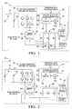
- FIG. 1is a diagrammatic drawing of the power system of the present invention.
- FIG. 2is a diagrammatic drawing of an alternate embodiment of the power system of the present invention.
- FIG. 1is a diagrammatic drawing of the power system of the present invention contained in a hybrid or electric vehicle 10 .
- the power systemincludes a DC supply 12 such as a battery or fuel cell coupled to a DC-DC converter and a DC contactor 14 to generate a high voltage DC bus V+.
- the voltage V+is preferably in the range of 200 to 450 volts, but may be varied to accommodate different vehicle power systems.
- the voltage V+is supplied to a motor inverter 18 via a filtering capacitor 16 .
- the motor inverter 18chops or switches the provided DC voltage V+ to preferably generate three phase power for a dual winding electric traction motor 20 .
- Inverter and motor control electronics 22control the switching of the motor inverter 18 as a function of motor speed, position and/or torque.
- the control electronics 22 of the present inventionmay comprise any type of control module or vehicle controller known in the art, and are equipped with nonvolatile memory (NVM), random access memory (RAM), discrete and analog input/output (I/O), a central processing unit, communications interfaces for conventional and wireless (Bluetooth®) networking within an automotive communications network.
- the control electronics 22may communicate with the motor inverter 18 using discrete signals, analog signals, or an automotive communications network.
- the inverter 18is preferably controlled using a space vector approach to the motor windings at a fundamental frequency, typically between zero and 400 hertz.
- the electric traction motor 20 used in the present inventionis preferably an AC induction machine but may comprise any known electrical motor/generator technology, including, but not limited to, DC machines, synchronous machines, and switched reluctance machines.
- the electric traction motor 20includes a primary winding or set of windings 24 on the motor stator coupled to the inverter 18 to receive the three phase time-varying current to create the magnetic fields that rotate the rotor of the electric traction motor 20 .
- a secondary winding or set of windings 26is electromagnetically coupled to the primary winding 24 on the motor stator and is wound with a turns ratio to provide a convenient voltage for rectification by a rectifier bridge 28 .
- the secondary winding 26is constructed so that each phase has a substantial leakage inductance of substantially 50 micro-henrys to 100 micro-henrys. This leakage inductance limits the current when each leg of the rectifier bridge 28 is turned on. This leakage inductance operates in discontinuous conduction, i.e., the current in each inductance returns to zero before the switch turns on in the next cycle.
- the rectifier bridge 28is preferably a three-phase rectifier with control switches S 1 , S 2 , S 3 in the top three legs and diodes 30 in the bottom three legs of the rectifier bridge 28 .
- the switches S 1 , S 2 , S 3are preferably silicon controlled rectifiers (SCRs) but may comprise any known electronic switching elements including, but not limited to, insulated gate bipolar transistors (IGBTs) and metal oxide semiconductor field effect transistors (MOSFETs).
- the conduction angle of the switches S 1 , S 2 , S 3is advanced or retarded in phase to control the output current and voltage of the rectifier bridge 28 by the control electronics 22 .
- the output voltage of the rectifier bridge 28is measured by a voltage sensor 32 .
- the control electronics 22may be used to implement a closed loop regulator for the output DC voltage of the rectifier bridge 28 by adjusting the switching or conduction of the switches S 1 , S 2 , S 3 in response to feedback from a voltage sensor 32 .
- the desired DC voltage output of the rectifier bridge 28 and the voltage feedback provided by the voltage sensor 32are subtracted at summing junction 40 to generate an error.
- the erroris input to proportional/integral (PI) control block 42 to generate discrete output to switches S 1 , S 2 , S 3 . In this manner, the switches S 1 , S 2 , S 3 will be modulated to provide the desired DC output voltage from the rectifier bridge 28 .
- PIproportional/integral
- the output current of the rectifier bridge 28is measured by current sensor 27 , and the inverter 18 is commanded by the control electronics 22 to compensate for the amount of current drawn by the secondary winding 26 , keeping the net current used for motoring constant and negating any torque ripple that would otherwise be caused by the power drawn from the secondary winding 26 .
- the stator voltageis directly proportional to motor speed or RPM.
- RPMmotor speed
- an operating conditionmay occur where the secondary output voltage generated by the secondary winding 26 and rectifier bridge 28 is no longer sufficient to produce the desired auxiliary voltage level.
- a high frequency signal(of substantially 400 hertz) is superimposed on the motoring frequency, and this high frequency signal is used to produce the auxiliary voltage level. The frequency of the signal is high enough such that it produces no net torque on the electric motor 20 rotor.
- FIG. 2includes the base elements of FIG. 1 with modification to the rectifier bridge 28 .
- the rectifier bridge 20 in FIG. 2can be implemented as a half bridge.
- the return currentflows to the neutral connection of the secondary winding 26 .
- the topology of FIG. 2has the advantage that the diodes 30 are eliminated from the circuit.
Landscapes
- Engineering & Computer Science (AREA)
- Power Engineering (AREA)
- Transportation (AREA)
- Mechanical Engineering (AREA)
- Life Sciences & Earth Sciences (AREA)
- Sustainable Development (AREA)
- Sustainable Energy (AREA)
- Electric Propulsion And Braking For Vehicles (AREA)
Abstract
Description
Claims (21)
Priority Applications (1)
| Application Number | Priority Date | Filing Date | Title |
|---|---|---|---|
| US09/947,294US6617820B2 (en) | 2001-09-07 | 2001-09-07 | Auxiliary power conversion by phase-controlled rectification |
Applications Claiming Priority (1)
| Application Number | Priority Date | Filing Date | Title |
|---|---|---|---|
| US09/947,294US6617820B2 (en) | 2001-09-07 | 2001-09-07 | Auxiliary power conversion by phase-controlled rectification |
Publications (2)
| Publication Number | Publication Date |
|---|---|
| US20030048089A1 US20030048089A1 (en) | 2003-03-13 |
| US6617820B2true US6617820B2 (en) | 2003-09-09 |
Family
ID=25485908
Family Applications (1)
| Application Number | Title | Priority Date | Filing Date |
|---|---|---|---|
| US09/947,294Expired - Fee RelatedUS6617820B2 (en) | 2001-09-07 | 2001-09-07 | Auxiliary power conversion by phase-controlled rectification |
Country Status (1)
| Country | Link |
|---|---|
| US (1) | US6617820B2 (en) |
Cited By (17)
| Publication number | Priority date | Publication date | Assignee | Title |
|---|---|---|---|---|
| US20020158610A1 (en)* | 2001-04-25 | 2002-10-31 | Denso Corporation | Vehicular power generation control device and method |
| US20040075413A1 (en)* | 2001-01-31 | 2004-04-22 | Jens Biebach | Power converter device for one of several motor windings on reluctance motor |
| US20060138995A1 (en)* | 2004-12-27 | 2006-06-29 | Nissan Motor Co., Ltd. | Generated power control system |
| US20070070668A1 (en)* | 2005-09-26 | 2007-03-29 | The Boeing Company | Programmable electrical power systems and methods |
| US20070088483A1 (en)* | 2003-12-26 | 2007-04-19 | Toyota Jidosha Kabushiki Kaisha | Hybrid system |
| US20080186750A1 (en)* | 2007-02-02 | 2008-08-07 | Rockwell Automation Technologies Inc. | Method and apparatus for DC bus capacitor pre-charge |
| US20080271935A1 (en)* | 2007-05-03 | 2008-11-06 | Erkan Mese | Multiple winding electric machine |
| US20080290764A1 (en)* | 2007-05-22 | 2008-11-27 | Halsey David G | Electrodynamic machine control |
| US20100072928A1 (en)* | 2008-09-23 | 2010-03-25 | Gm Global Technology Operations, Inc. | Electrical system for pulse-width modulated control of a power inverter using phase-shifted carrier signals and related operating methods |
| US20100071970A1 (en)* | 2008-09-23 | 2010-03-25 | Gm Global Technology Operations, Inc. | Electrical system using phase-shifted carrier signals and related operating methods |
| US20100320836A1 (en)* | 2009-06-18 | 2010-12-23 | Lear Corporation | Inverter with network interface |
| US20110012422A1 (en)* | 2009-07-14 | 2011-01-20 | Wabtec Holding Corp. | Power Generation and Distribution System Configured to Provide Power to a Motor |
| US20110022858A1 (en)* | 2009-07-23 | 2011-01-27 | Feeling Technology Corp. | Control circuit for power supplying |
| US20110157928A1 (en)* | 2009-12-29 | 2011-06-30 | Delta Electronics, Inc. | Dc-to-ac converting circuit with wide input voltage |
| DE102013204255A1 (en) | 2013-03-12 | 2014-09-18 | Bayerische Motoren Werke Aktiengesellschaft | Method and device for operating a vehicle electrical system |
| US20150035470A1 (en)* | 2013-08-05 | 2015-02-05 | GM Global Technology Operations LLC | Electric power assembly for a vehicle |
| US12191789B2 (en)* | 2021-03-29 | 2025-01-07 | Hitachi Construction Machinery Co., Ltd. | Drive system |
Families Citing this family (2)
| Publication number | Priority date | Publication date | Assignee | Title |
|---|---|---|---|---|
| US11533013B1 (en)* | 2021-07-29 | 2022-12-20 | Rivian Ip Holdings, Llc | Pulse width modulation clock synchronization |
| CN113676094B (en)* | 2021-07-29 | 2023-04-07 | 南京航空航天大学 | Control method of double-salient-pole generator full-bridge controllable power generation system |
Citations (9)
| Publication number | Priority date | Publication date | Assignee | Title |
|---|---|---|---|---|
| US3789281A (en)* | 1971-05-28 | 1974-01-29 | Kawasaki Heavy Ind Ltd | Electric control system of an electric machine arrangement combining electromagnetic coupling with an electric rotating machine |
| US4417193A (en)* | 1980-08-29 | 1983-11-22 | Tokyo Shibaura Denki Kabushiki Kaisha | Method and apparatus for controlling alternating current motors |
| US4423477A (en)* | 1979-07-02 | 1983-12-27 | Sangamo Weston, Inc. | Rectifier controller |
| US5151641A (en)* | 1989-08-21 | 1992-09-29 | Toyota Jidosha Kabushiki Kaisha | Electric automobile driving apparatus |
| US5350994A (en)* | 1992-06-05 | 1994-09-27 | Fuji Electric Co., Ltd. | Electric system for an electric vehicle |
| US5642270A (en)* | 1991-08-01 | 1997-06-24 | Wavedriver Limited | Battery powered electric vehicle and electrical supply system |
| US5659237A (en)* | 1995-09-28 | 1997-08-19 | Wisconsin Alumni Research Foundation | Battery charging using a transformer with a single primary winding and plural secondary windings |
| US6066928A (en)* | 1997-12-15 | 2000-05-23 | Fuji Electric Co., Ltd. | Electric system for electric vehicle |
| US6262896B1 (en)* | 2000-06-19 | 2001-07-17 | General Motors Corporation | Auxiliary power conversion for an electric vehicle using high frequency injection into a PWM inverter |
- 2001
- 2001-09-07USUS09/947,294patent/US6617820B2/ennot_activeExpired - Fee Related
Patent Citations (9)
| Publication number | Priority date | Publication date | Assignee | Title |
|---|---|---|---|---|
| US3789281A (en)* | 1971-05-28 | 1974-01-29 | Kawasaki Heavy Ind Ltd | Electric control system of an electric machine arrangement combining electromagnetic coupling with an electric rotating machine |
| US4423477A (en)* | 1979-07-02 | 1983-12-27 | Sangamo Weston, Inc. | Rectifier controller |
| US4417193A (en)* | 1980-08-29 | 1983-11-22 | Tokyo Shibaura Denki Kabushiki Kaisha | Method and apparatus for controlling alternating current motors |
| US5151641A (en)* | 1989-08-21 | 1992-09-29 | Toyota Jidosha Kabushiki Kaisha | Electric automobile driving apparatus |
| US5642270A (en)* | 1991-08-01 | 1997-06-24 | Wavedriver Limited | Battery powered electric vehicle and electrical supply system |
| US5350994A (en)* | 1992-06-05 | 1994-09-27 | Fuji Electric Co., Ltd. | Electric system for an electric vehicle |
| US5659237A (en)* | 1995-09-28 | 1997-08-19 | Wisconsin Alumni Research Foundation | Battery charging using a transformer with a single primary winding and plural secondary windings |
| US6066928A (en)* | 1997-12-15 | 2000-05-23 | Fuji Electric Co., Ltd. | Electric system for electric vehicle |
| US6262896B1 (en)* | 2000-06-19 | 2001-07-17 | General Motors Corporation | Auxiliary power conversion for an electric vehicle using high frequency injection into a PWM inverter |
Cited By (33)
| Publication number | Priority date | Publication date | Assignee | Title |
|---|---|---|---|---|
| US20040075413A1 (en)* | 2001-01-31 | 2004-04-22 | Jens Biebach | Power converter device for one of several motor windings on reluctance motor |
| US6975090B2 (en)* | 2001-01-31 | 2005-12-13 | Magnet-Motor Gesellschaft Fur Magnetmotorische Technik Mbh | Power converter device for one of several motor windings on reluctance motor |
| US6750634B2 (en)* | 2001-04-25 | 2004-06-15 | Denso Corporation | Vehicular power generation control device and method |
| US20020158610A1 (en)* | 2001-04-25 | 2002-10-31 | Denso Corporation | Vehicular power generation control device and method |
| US20070088483A1 (en)* | 2003-12-26 | 2007-04-19 | Toyota Jidosha Kabushiki Kaisha | Hybrid system |
| US7380621B2 (en)* | 2003-12-26 | 2008-06-03 | Toyota Jidosha Kabushiki Kaisha | Hybrid system |
| US7441616B2 (en)* | 2004-12-27 | 2008-10-28 | Nissan Motor Co., Ltd. | Generated power control system |
| US20060138995A1 (en)* | 2004-12-27 | 2006-06-29 | Nissan Motor Co., Ltd. | Generated power control system |
| US20070070668A1 (en)* | 2005-09-26 | 2007-03-29 | The Boeing Company | Programmable electrical power systems and methods |
| US20080186750A1 (en)* | 2007-02-02 | 2008-08-07 | Rockwell Automation Technologies Inc. | Method and apparatus for DC bus capacitor pre-charge |
| US8154895B2 (en)* | 2007-02-02 | 2012-04-10 | Rockwell Automation Technologies, Inc. | Method and apparatus for DC bus capacitor pre-charge |
| US20080271935A1 (en)* | 2007-05-03 | 2008-11-06 | Erkan Mese | Multiple winding electric machine |
| US20080290764A1 (en)* | 2007-05-22 | 2008-11-27 | Halsey David G | Electrodynamic machine control |
| US7782007B2 (en) | 2007-05-22 | 2010-08-24 | Hamilton Sundstrand Corporation | Electrodynamic machine control |
| US20100072928A1 (en)* | 2008-09-23 | 2010-03-25 | Gm Global Technology Operations, Inc. | Electrical system for pulse-width modulated control of a power inverter using phase-shifted carrier signals and related operating methods |
| US20100071970A1 (en)* | 2008-09-23 | 2010-03-25 | Gm Global Technology Operations, Inc. | Electrical system using phase-shifted carrier signals and related operating methods |
| US8115433B2 (en) | 2008-09-23 | 2012-02-14 | GM Global Technology Operations LLC | Electrical system for pulse-width modulated control of a power inverter using phase-shifted carrier signals and related operating methods |
| US8269434B2 (en)* | 2008-09-23 | 2012-09-18 | GM Global Technology Operations LLC | Electrical system using phase-shifted carrier signals and related operating methods |
| US8304929B2 (en)* | 2009-06-18 | 2012-11-06 | Lear Corporation | Inverter with network interface |
| USRE46230E1 (en)* | 2009-06-18 | 2016-12-06 | Lear Corporation | Inverter with network interface |
| US20100320836A1 (en)* | 2009-06-18 | 2010-12-23 | Lear Corporation | Inverter with network interface |
| US8102077B2 (en)* | 2009-07-14 | 2012-01-24 | Wabtec Holding Corp. | Power generation and distribution system configured to provide power to a motor |
| US20110012422A1 (en)* | 2009-07-14 | 2011-01-20 | Wabtec Holding Corp. | Power Generation and Distribution System Configured to Provide Power to a Motor |
| US20110022858A1 (en)* | 2009-07-23 | 2011-01-27 | Feeling Technology Corp. | Control circuit for power supplying |
| US8243474B2 (en)* | 2009-07-23 | 2012-08-14 | Feeling Technology Corp. | Control circuit for power supplying |
| US8467198B2 (en)* | 2009-12-29 | 2013-06-18 | Delta Electronics, Inc. | DC-to-AC converting circuit with wide input voltage |
| US20110157928A1 (en)* | 2009-12-29 | 2011-06-30 | Delta Electronics, Inc. | Dc-to-ac converting circuit with wide input voltage |
| DE102013204255A1 (en) | 2013-03-12 | 2014-09-18 | Bayerische Motoren Werke Aktiengesellschaft | Method and device for operating a vehicle electrical system |
| DE102013204255B4 (en)* | 2013-03-12 | 2025-07-17 | Bayerische Motoren Werke Aktiengesellschaft | Method and device for operating an on-board network |
| US20150035470A1 (en)* | 2013-08-05 | 2015-02-05 | GM Global Technology Operations LLC | Electric power assembly for a vehicle |
| US9203338B2 (en)* | 2013-08-05 | 2015-12-01 | GM Global Technology Operations LLC | Electric power assembly for a vehicle |
| DE102014110863B4 (en) | 2013-08-05 | 2021-11-04 | GM Global Technology Operations LLC (n. d. Ges. d. Staates Delaware) | Electrical power arrangement for a vehicle |
| US12191789B2 (en)* | 2021-03-29 | 2025-01-07 | Hitachi Construction Machinery Co., Ltd. | Drive system |
Also Published As
| Publication number | Publication date |
|---|---|
| US20030048089A1 (en) | 2003-03-13 |
Similar Documents
| Publication | Publication Date | Title |
|---|---|---|
| US6617820B2 (en) | Auxiliary power conversion by phase-controlled rectification | |
| US8054025B2 (en) | Charge control device and electrically driven vehicle | |
| Perreault et al. | Automotive power generation and control | |
| US7362597B2 (en) | AC voltage generating apparatus and motive power outputting apparatus | |
| US7956584B2 (en) | Electric power generation system with multiple alternators driven by a common prime mover | |
| US5175439A (en) | Power supply circuit for motor vehicles | |
| CA2282802C (en) | Apparatus and method to generate braking torque in an ac drive | |
| US6262896B1 (en) | Auxiliary power conversion for an electric vehicle using high frequency injection into a PWM inverter | |
| US7855901B2 (en) | AC voltage output apparatus and hybrid vehicle including the same | |
| US6384559B2 (en) | Electric power equipment for electric vehicle | |
| Babaki et al. | Analysis and control of wireless motor drives with a single inverter in primary side | |
| JPH02502421A (en) | Vehicle power system equipment | |
| US6608401B1 (en) | Alternator/inverter with dual H-bridge | |
| US20140103650A1 (en) | Dual-dc bus starter/generator | |
| JP2000358305A (en) | Power device for hybrid electric vehicle | |
| KR20100028403A (en) | Hybrid power apparatus | |
| JP2003061360A (en) | Rectifying circuit | |
| US7092267B2 (en) | Auxiliary power generation in a motor transformer | |
| JP5052255B2 (en) | AC rotating machine | |
| US12445075B2 (en) | Method and apparatus for an isolated DC/DC converter | |
| KR102745380B1 (en) | Charging system for electric vehicles | |
| US20230378895A1 (en) | Method and apparatus for an isolated dc/dc converter | |
| Jha et al. | A Multi-Functional Power Electronics Converter Configuration for Electric Vehicles | |
| JPH09322545A (en) | Voltage controller of permanent magnet generator | |
| WO2025210398A1 (en) | Method and system for managing charging and traction power flow in an electrical vehicle |
Legal Events
| Date | Code | Title | Description |
|---|---|---|---|
| AS | Assignment | Owner name:GENERAL MOTORS CORPORATION, MINNESOTA Free format text:ASSIGNMENT OF ASSIGNORS INTEREST;ASSIGNORS:CARLSON, DOUGLAS S.;STANCU, CONSTANTIN C.;NAGASHIMA, JAMES M.;AND OTHERS;REEL/FRAME:012156/0493 Effective date:20010828 | |
| FPAY | Fee payment | Year of fee payment:4 | |
| AS | Assignment | Owner name:GM GLOBAL TECHNOLOGY OPERATIONS, INC., MICHIGAN Free format text:ASSIGNMENT OF ASSIGNORS INTEREST;ASSIGNOR:GENERAL MOTORS CORPORATION;REEL/FRAME:022092/0703 Effective date:20050119 Owner name:GM GLOBAL TECHNOLOGY OPERATIONS, INC.,MICHIGAN Free format text:ASSIGNMENT OF ASSIGNORS INTEREST;ASSIGNOR:GENERAL MOTORS CORPORATION;REEL/FRAME:022092/0703 Effective date:20050119 | |
| AS | Assignment | Owner name:UNITED STATES DEPARTMENT OF THE TREASURY, DISTRICT Free format text:SECURITY AGREEMENT;ASSIGNOR:GM GLOBAL TECHNOLOGY OPERATIONS, INC.;REEL/FRAME:022201/0501 Effective date:20081231 | |
| AS | Assignment | Owner name:CITICORP USA, INC. AS AGENT FOR BANK PRIORITY SECU Free format text:SECURITY AGREEMENT;ASSIGNOR:GM GLOBAL TECHNOLOGY OPERATIONS, INC.;REEL/FRAME:022556/0013 Effective date:20090409 Owner name:CITICORP USA, INC. AS AGENT FOR HEDGE PRIORITY SEC Free format text:SECURITY AGREEMENT;ASSIGNOR:GM GLOBAL TECHNOLOGY OPERATIONS, INC.;REEL/FRAME:022556/0013 Effective date:20090409 | |
| AS | Assignment | Owner name:GM GLOBAL TECHNOLOGY OPERATIONS, INC., MICHIGAN Free format text:RELEASE BY SECURED PARTY;ASSIGNOR:UNITED STATES DEPARTMENT OF THE TREASURY;REEL/FRAME:023238/0015 Effective date:20090709 | |
| XAS | Not any more in us assignment database | Free format text:RELEASE BY SECURED PARTY;ASSIGNOR:UNITED STATES DEPARTMENT OF THE TREASURY;REEL/FRAME:023124/0383 | |
| AS | Assignment | Owner name:GM GLOBAL TECHNOLOGY OPERATIONS, INC., MICHIGAN Free format text:RELEASE BY SECURED PARTY;ASSIGNORS:CITICORP USA, INC. AS AGENT FOR BANK PRIORITY SECURED PARTIES;CITICORP USA, INC. AS AGENT FOR HEDGE PRIORITY SECURED PARTIES;REEL/FRAME:023127/0326 Effective date:20090814 | |
| AS | Assignment | Owner name:UNITED STATES DEPARTMENT OF THE TREASURY, DISTRICT Free format text:SECURITY AGREEMENT;ASSIGNOR:GM GLOBAL TECHNOLOGY OPERATIONS, INC.;REEL/FRAME:023155/0922 Effective date:20090710 | |
| AS | Assignment | Owner name:UAW RETIREE MEDICAL BENEFITS TRUST, MICHIGAN Free format text:SECURITY AGREEMENT;ASSIGNOR:GM GLOBAL TECHNOLOGY OPERATIONS, INC.;REEL/FRAME:023161/0864 Effective date:20090710 | |
| AS | Assignment | Owner name:GM GLOBAL TECHNOLOGY OPERATIONS, INC., MICHIGAN Free format text:RELEASE BY SECURED PARTY;ASSIGNOR:UAW RETIREE MEDICAL BENEFITS TRUST;REEL/FRAME:025311/0680 Effective date:20101026 Owner name:GM GLOBAL TECHNOLOGY OPERATIONS, INC., MICHIGAN Free format text:RELEASE BY SECURED PARTY;ASSIGNOR:UNITED STATES DEPARTMENT OF THE TREASURY;REEL/FRAME:025245/0273 Effective date:20100420 | |
| AS | Assignment | Owner name:WILMINGTON TRUST COMPANY, DELAWARE Free format text:SECURITY AGREEMENT;ASSIGNOR:GM GLOBAL TECHNOLOGY OPERATIONS, INC.;REEL/FRAME:025327/0222 Effective date:20101027 | |
| AS | Assignment | Owner name:GM GLOBAL TECHNOLOGY OPERATIONS LLC, MICHIGAN Free format text:CHANGE OF NAME;ASSIGNOR:GM GLOBAL TECHNOLOGY OPERATIONS, INC.;REEL/FRAME:025780/0795 Effective date:20101202 | |
| FPAY | Fee payment | Year of fee payment:8 | |
| REMI | Maintenance fee reminder mailed | ||
| LAPS | Lapse for failure to pay maintenance fees | ||
| STCH | Information on status: patent discontinuation | Free format text:PATENT EXPIRED DUE TO NONPAYMENT OF MAINTENANCE FEES UNDER 37 CFR 1.362 | |
| FP | Lapsed due to failure to pay maintenance fee | Effective date:20150909 |