US6616683B1 - Method of making miniaturized surgical forceps - Google Patents
Method of making miniaturized surgical forcepsDownload PDFInfo
- Publication number
- US6616683B1 US6616683B1US09/563,420US56342000AUS6616683B1US 6616683 B1US6616683 B1US 6616683B1US 56342000 AUS56342000 AUS 56342000AUS 6616683 B1US6616683 B1US 6616683B1
- Authority
- US
- United States
- Prior art keywords
- jaws
- forceps
- filler material
- tubular member
- opposed
- Prior art date
- Legal status (The legal status is an assumption and is not a legal conclusion. Google has not performed a legal analysis and makes no representation as to the accuracy of the status listed.)
- Expired - Fee Related
Links
- 238000004519manufacturing processMethods0.000titleclaims4
- 239000000463materialSubstances0.000claimsabstractdescription41
- 238000000034methodMethods0.000claimsabstractdescription22
- 239000000945fillerSubstances0.000claimsabstractdescription19
- 238000003754machiningMethods0.000claimsabstractdescription3
- 238000009760electrical discharge machiningMethods0.000claimsdescription8
- 238000005452bendingMethods0.000claimsdescription7
- 238000000151depositionMethods0.000claims5
- 239000011248coating agentSubstances0.000claims1
- 238000000576coating methodMethods0.000claims1
- PXHVJJICTQNCMI-UHFFFAOYSA-NNickelChemical compound[Ni]PXHVJJICTQNCMI-UHFFFAOYSA-N0.000description6
- 238000001356surgical procedureMethods0.000description6
- UONOETXJSWQNOL-UHFFFAOYSA-Ntungsten carbideChemical compound[W+]#[C-]UONOETXJSWQNOL-UHFFFAOYSA-N0.000description5
- 239000007788liquidSubstances0.000description4
- 239000000835fiberSubstances0.000description3
- 239000012530fluidSubstances0.000description3
- 229910052759nickelInorganic materials0.000description3
- 230000003287optical effectEffects0.000description3
- 230000002787reinforcementEffects0.000description3
- 239000003082abrasive agentSubstances0.000description2
- 229910003460diamondInorganic materials0.000description2
- 239000010432diamondSubstances0.000description2
- 239000000428dustSubstances0.000description2
- 238000003384imaging methodMethods0.000description2
- 238000001802infusionMethods0.000description2
- 239000007924injectionSubstances0.000description2
- 238000002347injectionMethods0.000description2
- TWNQGVIAIRXVLR-UHFFFAOYSA-Noxo(oxoalumanyloxy)alumaneChemical compoundO=[Al]O[Al]=OTWNQGVIAIRXVLR-UHFFFAOYSA-N0.000description2
- 239000000843powderSubstances0.000description2
- 239000000523sampleSubstances0.000description2
- 229920002379silicone rubberPolymers0.000description2
- 239000004945silicone rubberSubstances0.000description2
- TXEYQDLBPFQVAA-UHFFFAOYSA-NtetrafluoromethaneChemical compoundFC(F)(F)FTXEYQDLBPFQVAA-UHFFFAOYSA-N0.000description2
- 210000001519tissueAnatomy0.000description2
- 208000002367Retinal PerforationsDiseases0.000description1
- 206010038897Retinal tearDiseases0.000description1
- 210000002159anterior chamberAnatomy0.000description1
- 210000002555descemet membraneAnatomy0.000description1
- 239000007789gasSubstances0.000description1
- 230000002262irrigationEffects0.000description1
- 238000003973irrigationMethods0.000description1
- 238000012986modificationMethods0.000description1
- 230000004048modificationEffects0.000description1
- 239000013307optical fiberSubstances0.000description1
- 229910001220stainless steelInorganic materials0.000description1
- 239000010935stainless steelSubstances0.000description1
Images


Classifications
- A—HUMAN NECESSITIES
- A61—MEDICAL OR VETERINARY SCIENCE; HYGIENE
- A61B—DIAGNOSIS; SURGERY; IDENTIFICATION
- A61B17/00—Surgical instruments, devices or methods
- A61B17/28—Surgical forceps
- A61B17/29—Forceps for use in minimally invasive surgery
- A—HUMAN NECESSITIES
- A61—MEDICAL OR VETERINARY SCIENCE; HYGIENE
- A61B—DIAGNOSIS; SURGERY; IDENTIFICATION
- A61B17/00—Surgical instruments, devices or methods
- A61B17/30—Surgical pincettes, i.e. surgical tweezers without pivotal connections
- A—HUMAN NECESSITIES
- A61—MEDICAL OR VETERINARY SCIENCE; HYGIENE
- A61B—DIAGNOSIS; SURGERY; IDENTIFICATION
- A61B17/00—Surgical instruments, devices or methods
- A61B17/28—Surgical forceps
- A61B17/2812—Surgical forceps with a single pivotal connection
- A61B17/282—Jaws
- A61B2017/2825—Inserts of different material in jaws
- A—HUMAN NECESSITIES
- A61—MEDICAL OR VETERINARY SCIENCE; HYGIENE
- A61B—DIAGNOSIS; SURGERY; IDENTIFICATION
- A61B17/00—Surgical instruments, devices or methods
- A61B17/28—Surgical forceps
- A61B17/29—Forceps for use in minimally invasive surgery
- A61B2017/2926—Details of heads or jaws
- A—HUMAN NECESSITIES
- A61—MEDICAL OR VETERINARY SCIENCE; HYGIENE
- A61B—DIAGNOSIS; SURGERY; IDENTIFICATION
- A61B17/00—Surgical instruments, devices or methods
- A61B17/28—Surgical forceps
- A61B17/29—Forceps for use in minimally invasive surgery
- A61B2017/2926—Details of heads or jaws
- A61B2017/2932—Transmission of forces to jaw members
- A61B2017/2933—Transmission of forces to jaw members camming or guiding means
- A61B2017/2937—Transmission of forces to jaw members camming or guiding means with flexible part
- A—HUMAN NECESSITIES
- A61—MEDICAL OR VETERINARY SCIENCE; HYGIENE
- A61B—DIAGNOSIS; SURGERY; IDENTIFICATION
- A61B17/00—Surgical instruments, devices or methods
- A61B17/30—Surgical pincettes, i.e. surgical tweezers without pivotal connections
- A61B2017/305—Tweezer like handles with tubular extensions, inner slidable actuating members and distal tools, e.g. microsurgical instruments
Definitions
- the present inventionrelates generally to the field of surgical instruments, particularly instruments employed in ophthalmologic surgical procedures,
- the present inventionrelates to miniaturized surgical forceps which are especially well suited for ophthalmologic surgical procedures, for example.
- instrumentsare positioned within the anterior chamber or vitreous cavity through microscopic incisions through the eye wall.
- Each placement and removal of an instrumentcan cause damage to adjacent structures (such as retinal tear with detachment or tear of Descemet's membrane).
- a goal, therefore,is to limit the number of times instruments are introduced and replaced within the eye during intraocular surgery.
- a surgical instrumentespecially forceps, could be provided which are particularly well suited for use during intraocular surgery that had a hollow lumen.
- Such an instrumentwould therefore allow for the delivery of materials and/or secondary instruments in concert with the forceps action and thereby decrease the need for repeated withdrawal and reinsertion of instruments and material delivery devices.
- the actions that could be performed with such an instrumentinclude, the infusion of intraocular liquid or gas; injection of specific fluids such as a dye or a perfluorocarbon liquid; manipulation with small picks, hooks, aspirating cannula or blunt probe, optical diagnostics and imaging by means of video fiber or other optical diagnostic fiber; cutting with a fine scalpel or laser fiber; and/or delivery of light or laser energy.
- the present inventionis embodied in miniature surgical forceps formed from a lumen-defining tubular member.
- the hollow lumen of the miniature surgical forceps of the present inventionthereby permit the actions noted immediately above to be performed in simultaneously in concert with the forceps action. That is, the safe delivery of additional instrumentation to the surgical site can be performed in concert with the actions of the microforceps tip without removing instruments through the eye wall.
- the forceps of the present inventionhave greatly improved and enhanced utility since additional instrumentation may be utilized to work with or aid in positioning of tissues with the grasp of the forceps.
- the miniature surgical forceps of the present inventionare provided with opposed longitudinal channels machined in a distal end of a tubular member so as to establish an opposed pair of forceps jaws.
- the opposed channelsare formed in the distal end of the rigid tubular member by means of electrical discharge machining (EDM) techniques.
- EDMelectrical discharge machining
- opposed radial channelsare formed in a lengthwise extent of the distal end of a rigid tubular member by EDM techniques.
- the resulting opposed cross-sectionally arcuate jaw sectionsmay be bent and/or further shaped to achieve the desired final jaw configuration.
- the inner surfaces of the forceps jaws thereby establishedmay be provided with a suitable filler material so as to establish a desired forceps surface.
- the filler materialmay be a hardened material (e.g., a tungsten carbide, electroless nickel or like hardened materials) to provide structural reinforcement to the forceps jaws or may be a compliant material, such as an elastomeric (e.g., silicone rubber) type material. These materials may thus be deposited onto the forceps jaws in a manner which changes the overall shape and/or geometric configuration of the jaws and thereby engineer them to a specific surgical purpose.
- the filler materialmay be coated with a desired abrasive material (e.g., fine powders of diamond dust, aluminum oxide, tungsten carbide and the like) so as to increase the forceps jaws' coefficient of friction.
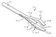
- FIG. 1is a side elevation view showing one exemplary embodiment of a miniaturized surgical forceps according to the present invention
- FIG. 2is an enlarged elevational view of the tip employed in the surgical forceps of FIG. 1;
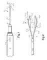
- FIGS. 3A-3Dis a schematic perspective views showing the manner in which the surgical forceps of this invention is made.
- FIGS. 4-6are each enlarged elevational views depicting other possible tip embodiments for the surgical forceps of the present invention.
- FIG. 1shows one preferred embodiment of a surgical instrument 10 according to the present invention.
- the instrument 10includes a proximal handle section 12 , a distal forceps section 14 and an intermediate tubular support section 16 .
- the intermediate tubular support section 16may itself be sleeved within a proximal reinforcement tube 18 as may be desired for purposes of imparting structural integrity to the instrument 10 .
- the handle section 12is, in and of itself, highly conventional.
- the handle section 12may be conventional Sutherland-type handles of the variety disclosed in U.S. Pat. No. 5,634,918 (the entire content of which is incorporated hereinto fully by reference) or the omni-actuatable hand-held device disclosed in U.S. Pat. No. 6,391,046 B1 (the entire content of which is expressly incorporated hereinto by reference).
- the handle section 12may also be motor-actuated, if desired.
- the handle section 12is coupled operatively to the proximally extending stem 14 - 1 of the forceps section 14 .
- the stem 14 - 1can be caused to retract rearwardly within the intermediate tubular section 16 with which it is coaxially sleeved. Retraction of the forceps stem 14 - 1 will, in turn, cause the opposed jaws 14 - 2 to be forcibly moved toward one another against their inherent resilient forces.
- the actuator 12 - 1may be coupled to one end of wires (not shown) whose other end is attached to a respective one of the jaws 14 - 2 . Movement of the button 12 - 1 will thereby cause the jaws 14 - 2 to move towards and away from one another as may be desired.
- FIG. 2perhaps shows the distal forceps section 14 in greater clarity.
- the opposed forceps jaws 14 - 2are established by a longitudinally extending channel 14 - 3 formed in a distalmost section of the tubular forceps stem 14 - 1 .
- Each of the forceps jaws 14 - 2is therefore the cross-sectionally arcuate, unitary (i.e., one-piece) remnant of the distalmost section of the tubular forceps stem 14 - 1 .
- These remnantshave thus been further fashioned by a proximal outwardly bent section 14 - 2 a and an immediately distal inwardly bent section 14 - 2 b.
- the jaws 14 - 2thereby fashioned are generally V-shaped which provides a seat for a suitable filler material 14 - 4 which thereby forms the opposed gripping surfaces 14 - 5 of the forceps jaws 14 - 2 .
- the filler material 14 - 4may be a hardened material (e.g., a tungsten carbide, electroless nickel or like hardened materials) to provide structural reinforcement to the forceps jaws 14 - 2 or may be a compliant material, such as an elastomeric (e.g., silicone rubber) type material. These materials may thus be deposited onto the forceps jaws in a manner which changes the overall shape and/or geometric configuration of the jaws and thereby engineer them to a specific surgical purpose.
- the filler material 14 - 4may be coated with a desired abrasive material (e.g., fine powders of diamond dust, aluminum oxide, tungsten carbide and the like) so as to increase the forceps jaws' coefficient of friction.
- a desired abrasive materiale.g., fine powders of diamond dust, aluminum oxide, tungsten carbide and the like
- the lumen defined by the longitudinally extending channel 14 - 3 of the tubular forceps stem 14 - 1provides a convenient means by which an elongate element (shown schematically by dashed line in FIG. 2 as reference numeral 15 ) may be employed by the attending surgeon.
- the elongate element 15may be any of a variety of devices that may be needed by the attending surgeon for use in concert with the forceps.
- the element 15may be tubular so as to allow the infusion of intraocular liquid or gas, injection of specific fluids such as a dye or a perfluorocarbon liquid or the like.
- the distal end of the element 15may be in the form of a miniature pick, hooks, aspirating cannula, blunt probe, scalpel or the like that may be needed by the surgeon.
- the element 15may be an optical fiber to allow optical diagnostics and imaging to be accomplished and/or for the delivery of laser light energy as may be needed.
- FIGS. 3A-3Dschematically depict a presently preferred technique for forming the miniature forceps 10 of this invention.
- the distal end of a length of tubinge.g., a section of a conventional 19 ga. or smaller stainless steel tubular needle
- the EDM wire 20 - 1When energized, the EDM wire 20 - 1 thereby removes material from the distal end of the stem 14 - 1 forming radially opposed, longitudinally extending channels 14 - 3 thereby establishing the opposed pair of forceps jaws 14 - 2 as shown in FIG. 3 B.
- each of the cross-sectionally arcuate jaws 14 - 2have been further fashioned by bending so as to form the proximal outwardly bent section 14 - 2 a and the immediately distal inwardly bent section 14 - 2 b . It will be seen in FIG. 3C that the section 14 - 2 a is bent outwardly at a location which is distal to the proximal extent of channels 14 - 3 .
- the generally V-shaped jaws 14 - 2 thereby fashionedmay then receive a suitable hardened material (e.g., a tungsten carbide, electroless nickel or like hardened materials) which thereby forms the opposed gripping surfaces 14 - 4 of the forceps jaws 14 - 2 as shown in FIG. 3 D.
- a suitable hardened materiale.g., a tungsten carbide, electroless nickel or like hardened materials
- the lumen of the stem 14 - 1is open to the space defined between the jaws 14 - 2 .
- the instrumentmay be connected to a aspiration source providing suction through the lumen of the stem 14 - 1 which may assist the surgeon to more easily grasp desired tissue.
- the lumen of the stem 14 - 1may be connected to a source of irrigation fluid to allow the surgeon to irrigate the surgical field simultaneously while operating the miniature forceps jaws 14 - 2 of the instrument 10 .
- the forceps jaws 14 - 2may be fashioned as desired so as to achieve a wide variety of jaw designs suitable for specific surgical purposes.
- the forceps jaws 14 - 2 ′ shown in FIG. 4may be provided with multiple bends and machined so as to exhibit a relatively blunt tip, while the forceps jaws 14 - 2 ′′ may be machined to exhibit a relatively sharp tip.
- the filler materialmay be omitted from the forceps jaws 14 - 2 ′′′.
Landscapes
- Health & Medical Sciences (AREA)
- Surgery (AREA)
- Life Sciences & Earth Sciences (AREA)
- Biomedical Technology (AREA)
- Nuclear Medicine, Radiotherapy & Molecular Imaging (AREA)
- Engineering & Computer Science (AREA)
- Ophthalmology & Optometry (AREA)
- Heart & Thoracic Surgery (AREA)
- Medical Informatics (AREA)
- Molecular Biology (AREA)
- Animal Behavior & Ethology (AREA)
- General Health & Medical Sciences (AREA)
- Public Health (AREA)
- Veterinary Medicine (AREA)
- Surgical Instruments (AREA)
Abstract
Description
The present invention relates generally to the field of surgical instruments, particularly instruments employed in ophthalmologic surgical procedures, In preferred forms, the present invention relates to miniaturized surgical forceps which are especially well suited for ophthalmologic surgical procedures, for example.
During intraocular surgery, instruments are positioned within the anterior chamber or vitreous cavity through microscopic incisions through the eye wall. Each placement and removal of an instrument can cause damage to adjacent structures (such as retinal tear with detachment or tear of Descemet's membrane). A goal, therefore, is to limit the number of times instruments are introduced and replaced within the eye during intraocular surgery.
It would therefore be highly desirable if a surgical instrument, especially forceps, could be provided which are particularly well suited for use during intraocular surgery that had a hollow lumen. Such an instrument would therefore allow for the delivery of materials and/or secondary instruments in concert with the forceps action and thereby decrease the need for repeated withdrawal and reinsertion of instruments and material delivery devices. For example, the actions that could be performed with such an instrument include, the infusion of intraocular liquid or gas; injection of specific fluids such as a dye or a perfluorocarbon liquid; manipulation with small picks, hooks, aspirating cannula or blunt probe, optical diagnostics and imaging by means of video fiber or other optical diagnostic fiber; cutting with a fine scalpel or laser fiber; and/or delivery of light or laser energy.
Broadly, the present invention is embodied in miniature surgical forceps formed from a lumen-defining tubular member. The hollow lumen of the miniature surgical forceps of the present invention thereby permit the actions noted immediately above to be performed in simultaneously in concert with the forceps action. That is, the safe delivery of additional instrumentation to the surgical site can be performed in concert with the actions of the microforceps tip without removing instruments through the eye wall. Thus, the forceps of the present invention have greatly improved and enhanced utility since additional instrumentation may be utilized to work with or aid in positioning of tissues with the grasp of the forceps.
According to preferred embodiments, the miniature surgical forceps of the present invention are provided with opposed longitudinal channels machined in a distal end of a tubular member so as to establish an opposed pair of forceps jaws. Most preferably, the opposed channels are formed in the distal end of the rigid tubular member by means of electrical discharge machining (EDM) techniques. Thus, according to the present invention, opposed radial channels are formed in a lengthwise extent of the distal end of a rigid tubular member by EDM techniques. The resulting opposed cross-sectionally arcuate jaw sections may be bent and/or further shaped to achieve the desired final jaw configuration.
The inner surfaces of the forceps jaws thereby established may be provided with a suitable filler material so as to establish a desired forceps surface. For example, the filler material may be a hardened material (e.g., a tungsten carbide, electroless nickel or like hardened materials) to provide structural reinforcement to the forceps jaws or may be a compliant material, such as an elastomeric (e.g., silicone rubber) type material. These materials may thus be deposited onto the forceps jaws in a manner which changes the overall shape and/or geometric configuration of the jaws and thereby engineer them to a specific surgical purpose. In addition, the filler material may be coated with a desired abrasive material (e.g., fine powders of diamond dust, aluminum oxide, tungsten carbide and the like) so as to increase the forceps jaws' coefficient of friction.
These and other aspects and advantages of the present invention will become more clear from the following detailed description of the preferred exemplary embodiments thereof.
Reference will hereinafter be made to the accompanying drawings, wherein like reference numerals throughout the various FIGURES denote like structural elements, and wherein,
FIG. 1 is a side elevation view showing one exemplary embodiment of a miniaturized surgical forceps according to the present invention;
FIG. 2 is an enlarged elevational view of the tip employed in the surgical forceps of FIG. 1;
FIGS. 3A-3D is a schematic perspective views showing the manner in which the surgical forceps of this invention is made;
FIGS. 4-6 are each enlarged elevational views depicting other possible tip embodiments for the surgical forceps of the present invention.
Accompanying FIG. 1 shows one preferred embodiment of asurgical instrument 10 according to the present invention. In this regard, theinstrument 10 includes aproximal handle section 12, adistal forceps section 14 and an intermediatetubular support section 16. The intermediatetubular support section 16 may itself be sleeved within aproximal reinforcement tube 18 as may be desired for purposes of imparting structural integrity to theinstrument 10.
Thehandle section 12 is, in and of itself, highly conventional. For example, thehandle section 12 may be conventional Sutherland-type handles of the variety disclosed in U.S. Pat. No. 5,634,918 (the entire content of which is incorporated hereinto fully by reference) or the omni-actuatable hand-held device disclosed in U.S. Pat. No. 6,391,046 B1 (the entire content of which is expressly incorporated hereinto by reference). Thehandle section 12 may also be motor-actuated, if desired.
Thehandle section 12 is coupled operatively to the proximally extending stem14-1 of theforceps section 14. By manipulating the handle section's actuator (which is shown schematically by reference numeral12-1 in FIG.1), the stem14-1 can be caused to retract rearwardly within the intermediatetubular section 16 with which it is coaxially sleeved. Retraction of the forceps stem14-1 will, in turn, cause the opposed jaws14-2 to be forcibly moved toward one another against their inherent resilient forces. Alternatively or additionally, the actuator12-1 may be coupled to one end of wires (not shown) whose other end is attached to a respective one of the jaws14-2. Movement of the button12-1 will thereby cause the jaws14-2 to move towards and away from one another as may be desired.
Accompanying FIG. 2 perhaps shows thedistal forceps section 14 in greater clarity. As shown, the opposed forceps jaws14-2 are established by a longitudinally extending channel14-3 formed in a distalmost section of the tubular forceps stem14-1. Each of the forceps jaws14-2 is therefore the cross-sectionally arcuate, unitary (i.e., one-piece) remnant of the distalmost section of the tubular forceps stem14-1. These remnants have thus been further fashioned by a proximal outwardly bent section14-2a and an immediately distal inwardly bent section14-2b. The jaws14-2 thereby fashioned are generally V-shaped which provides a seat for a suitable filler material14-4 which thereby forms the opposed gripping surfaces14-5 of the forceps jaws14-2.
The filler material14-4 may be a hardened material (e.g., a tungsten carbide, electroless nickel or like hardened materials) to provide structural reinforcement to the forceps jaws14-2 or may be a compliant material, such as an elastomeric (e.g., silicone rubber) type material. These materials may thus be deposited onto the forceps jaws in a manner which changes the overall shape and/or geometric configuration of the jaws and thereby engineer them to a specific surgical purpose. In addition, the filler material14-4 may be coated with a desired abrasive material (e.g., fine powders of diamond dust, aluminum oxide, tungsten carbide and the like) so as to increase the forceps jaws' coefficient of friction.
As noted above, the lumen defined by the longitudinally extending channel14-3 of the tubular forceps stem14-1 provides a convenient means by which an elongate element (shown schematically by dashed line in FIG. 2 as reference numeral15) may be employed by the attending surgeon. Theelongate element 15 may be any of a variety of devices that may be needed by the attending surgeon for use in concert with the forceps. Thus, theelement 15 may be tubular so as to allow the infusion of intraocular liquid or gas, injection of specific fluids such as a dye or a perfluorocarbon liquid or the like. The distal end of theelement 15 may be in the form of a miniature pick, hooks, aspirating cannula, blunt probe, scalpel or the like that may be needed by the surgeon. Alternatively, theelement 15 may be an optical fiber to allow optical diagnostics and imaging to be accomplished and/or for the delivery of laser light energy as may be needed.
Accompanying FIGS. 3A-3D schematically depict a presently preferred technique for forming theminiature forceps 10 of this invention. As shown in FIG. 3A, the distal end of a length of tubing (e.g., a section of a conventional 19 ga. or smaller stainless steel tubular needle) forming the stem14-1 is axially translated relative to an EDM wire20-1 provided as a component part of aconventional EDM system 20. When energized, the EDM wire20-1 thereby removes material from the distal end of the stem14-1 forming radially opposed, longitudinally extending channels14-3 thereby establishing the opposed pair of forceps jaws14-2 as shown in FIG.3B. It will be observed that the jaws in FIG. 3B have not been further fashioned by bending, but instead are depicted in a state immediately following the machining by the EDM system. However, in FIG. 3C, each of the cross-sectionally arcuate jaws14-2 have been further fashioned by bending so as to form the proximal outwardly bent section14-2aand the immediately distal inwardly bent section14-2b. It will be seen in FIG. 3C that the section14-2ais bent outwardly at a location which is distal to the proximal extent of channels14-3. The generally V-shaped jaws14-2 thereby fashioned may then receive a suitable hardened material (e.g., a tungsten carbide, electroless nickel or like hardened materials) which thereby forms the opposed gripping surfaces14-4 of the forceps jaws14-2 as shown in FIG.3D.
It will be understood, that the lumen of the stem14-1 is open to the space defined between the jaws14-2. Such a structural attribute of theforceps instrument 10 of this invention can be quite advantageous during certain surgical procedures. Thus, for example, the instrument may be connected to a aspiration source providing suction through the lumen of the stem14-1 which may assist the surgeon to more easily grasp desired tissue. Alternatively, the lumen of the stem14-1 may be connected to a source of irrigation fluid to allow the surgeon to irrigate the surgical field simultaneously while operating the miniature forceps jaws14-2 of theinstrument 10.
The forceps jaws14-2 may be fashioned as desired so as to achieve a wide variety of jaw designs suitable for specific surgical purposes. For example, the forceps jaws14-2′ shown in FIG. 4 may be provided with multiple bends and machined so as to exhibit a relatively blunt tip, while the forceps jaws14-2″ may be machined to exhibit a relatively sharp tip. And, as shown in FIG. 6, the filler material may be omitted from the forceps jaws14-2′″.
While the invention has been described in connection with what is presently considered to be the most practical and preferred embodiment, it is to be understood that the invention is not to be limited to the disclosed embodiment, but on the contrary, is intended to cover various modifications and equivalent arrangements included within the spirit and scope of the appended claims.
Claims (21)
1. A method of making miniature surgical forceps comprising providing a 19 gauge or smaller rigid tubular member, and removing material from longitudinal regions of a distal end of said tubular member so as to form respective longitudinally extending channels therein which thereby define an opposed pair of forceps jaws from respective remnants of said distal end of said tubular member.
2. The method ofclaim 1 , wherein said material is removed from radially opposed longitudinal regions of said distal end of said rigid tubula member so as to form a respective pair of radially opposed longitudinally extending channels therein.
3. The method ofclaim 1 or2 , further comprising depositing a filler material onto said respective remnants.
4. The method ofclaim 3 , wherein said filler material is deposited onto an interior of each of said respective remnants.
5. The method ofclaim 4 , wherein said filler material is selected from hardened or compliant materials.
6. The method ofclaim 3 , further comprising an abrasive coating on at least a surface portion of said filler material.
7. The method ofclaim 1 or2 , further comprising bending said remaining remnants into a generally V-shaped configuration.
8. The method ofclaim 7 , further comprising depositing a filler material onto said V-shaped configuration of said respective remnants.
9. The method ofclaim 8 , wherein said filler material is deposited onto an interior of each of said respective remnants.
10. The method ofclaim 1 or2 , wherein said material is removed using electrical discharge machining.
11. A method of making miniature forceps comprising forming a radially opposed pair of proximally extending longitudinal channels in a distalmost end of a 19 gauge or smaller rigid tubular member to thereby establish an opposed pair of forceps jaws thereat, wherein said channels are formed by removing material from said distalmost end of said rigid tubular member.
12. The method ofclaim 11 , wherein said material is removed by electrical discharge machining.
13. The method ofclaim 11 , further comprising depositing a filler material onto said respective jaws.
14. The method ofclaim 13 wherein said filler material is deposited onto an interior of each of said jaws.
15. The method ofclaim 11 , further comprising bending said jaws into a generally V-shaped configuration.
16. The method ofclaim 15 , further comprising depositing a filler material onto said V-shaped configuration of said jaws.
17. The method ofclaim 16 , wherein said filler material is deposited onto an interior of each of said respective jaws.
18. A method of making miniature surgical forceps comprising the steps of:
(i) providing a 19 gauge or smaller rigid tubular member;
(ii) effecting relative axial translation between a distal end of the tubular member and an energized wire associated with an electron discharge machining (EDM) system so as to remove material from said distal end of the tubular member so as to form a pair of radially opposed, longitudinally extending channels which thereby establish an opposed pair of cross-sectionally arcuate remnant sections at said distal end; and thereafter
(iii) outwardly bending said remnant sections to establish an opposed pair of forceps jaws.
19. The method ofclaim 18 , wherein step (iii) is practiced by bending said remnant sections at a location distally of a proximal extent of said channels.
20. The method ofclaim 19 , wherein step (iii) is practiced by bending a proximal outwardly bent section and an immediately distal inwardly bent section so as to form a pair of opposed generally V-shaped forceps jaws.
21. The method ofclaim 20 , which comprises depositing a filler material into said cross-sectionally arcuate remnants.
Priority Applications (5)
| Application Number | Priority Date | Filing Date | Title |
|---|---|---|---|
| US09/563,420US6616683B1 (en) | 2000-05-02 | 2000-05-02 | Method of making miniaturized surgical forceps |
| AU2001255662AAU2001255662A1 (en) | 2000-05-02 | 2001-04-26 | Miniaturized surgical forceps and methods of making the same |
| EP01928848AEP1278466A4 (en) | 2000-05-02 | 2001-04-26 | Miniaturized surgical forceps and methods of making the same |
| PCT/US2001/013297WO2001082808A1 (en) | 2000-05-02 | 2001-04-26 | Miniaturized surgical forceps and methods of making the same |
| ARP010102008AAR028387A1 (en) | 2000-05-02 | 2001-04-27 | MINIATURIZED SURGICAL FORCPS AND METHODS FOR PRODUCTION |
Applications Claiming Priority (1)
| Application Number | Priority Date | Filing Date | Title |
|---|---|---|---|
| US09/563,420US6616683B1 (en) | 2000-05-02 | 2000-05-02 | Method of making miniaturized surgical forceps |
Publications (1)
| Publication Number | Publication Date |
|---|---|
| US6616683B1true US6616683B1 (en) | 2003-09-09 |
Family
ID=24250421
Family Applications (1)
| Application Number | Title | Priority Date | Filing Date |
|---|---|---|---|
| US09/563,420Expired - Fee RelatedUS6616683B1 (en) | 2000-05-02 | 2000-05-02 | Method of making miniaturized surgical forceps |
Country Status (5)
| Country | Link |
|---|---|
| US (1) | US6616683B1 (en) |
| EP (1) | EP1278466A4 (en) |
| AR (1) | AR028387A1 (en) |
| AU (1) | AU2001255662A1 (en) |
| WO (1) | WO2001082808A1 (en) |
Cited By (58)
| Publication number | Priority date | Publication date | Assignee | Title |
|---|---|---|---|---|
| US20040193214A1 (en)* | 2002-06-12 | 2004-09-30 | Scheller Gregg D. | Surgical instrument constructed by electric discharge machining |
| US20050234507A1 (en)* | 2004-04-16 | 2005-10-20 | Jeff Geske | Medical tool for access to internal tissue |
| US20050267506A1 (en)* | 2004-04-08 | 2005-12-01 | Harris James A | Follicular extraction method and device |
| US20070213766A1 (en)* | 2006-03-13 | 2007-09-13 | Sundaram Ravikumar | Minimally Invasive Surgical Assembly and Methods |
| US20070213767A1 (en)* | 2006-03-13 | 2007-09-13 | Sundaram Ravikumar | Minimally invasive surgical assembly and methods |
| US20070213595A1 (en)* | 2006-03-13 | 2007-09-13 | Sundaram Ravikumar | Minimally invasive rake retractor and method for using same |
| US20070239202A1 (en)* | 2006-04-10 | 2007-10-11 | Rodriguez Richard A | Abrasively coated surgical end effector |
| US20070250112A1 (en)* | 2006-03-13 | 2007-10-25 | Sundaram Ravikumar | Minimally Invasive Surgical Assembly and Methods |
| US20070282170A1 (en)* | 2006-05-30 | 2007-12-06 | Sundaram Ravikumar | Rake Retractor and Needle Assembly for Minimally Invasive Surgical Applications |
| US20080058761A1 (en)* | 2006-03-02 | 2008-03-06 | Richard Spaide | Diamond Dusted Extrusion Cannula |
| US20080086166A1 (en)* | 2006-10-10 | 2008-04-10 | Sundaram Ravikumar | Minimally Invasive Surgical Assembly with Balloon Instrument |
| US20090005765A1 (en)* | 2007-06-26 | 2009-01-01 | Restoration Robotics, Inc. | Follicular unit harvesting tools including devices and their use for severing connective tissue |
| US20090259225A1 (en)* | 2008-04-09 | 2009-10-15 | Sundaram Ravikumar | Minimally Invasive Surgical Needle and Cauterizing Assembly and Methods |
| US20100114118A1 (en)* | 2004-04-08 | 2010-05-06 | Hsc Development Llc | Follicular extraction method and device |
| US20100292724A1 (en)* | 2006-03-13 | 2010-11-18 | Sundaram Ravikumar | Minimally Invasive Surgical Clamps, Assemblies and Methods |
| US20110213409A1 (en)* | 2010-02-25 | 2011-09-01 | Martin Leonhard | Medical instrument |
| WO2012024227A1 (en)* | 2010-08-16 | 2012-02-23 | Boston Scientific Scimed, Inc. | Tissue sampling device |
| USD659826S1 (en)* | 2011-02-03 | 2012-05-15 | St. Jude Medical, Inc. | Tissue clamping member |
| US8414616B2 (en) | 2006-09-12 | 2013-04-09 | Pioneer Surgical Technology, Inc. | Mounting devices for fixation devices and insertion instruments used therewith |
| US20150088193A1 (en)* | 2013-09-24 | 2015-03-26 | Katalyst Surgical, Llc | Membrane removing forceps |
| US9326757B2 (en) | 2009-12-31 | 2016-05-03 | Teleflex Medical Incorporated | Surgical instruments for laparoscopic aspiration and retraction |
| USD772680S1 (en)* | 2011-08-31 | 2016-11-29 | Labplas Inc. | Handle for holding a sampling sponge |
| EP2632351A4 (en)* | 2010-10-28 | 2017-06-07 | Pare Surgical, Inc. | Percutaneous tissue grasping apparatus and method |
| US9925647B2 (en) | 2011-11-10 | 2018-03-27 | Labplas Inc. | Device for holding a sampling sponge |
| US9931114B2 (en) | 2010-09-10 | 2018-04-03 | Pivot Medical, Inc. | Method and apparatus for passing suture through tissue |
| USD825058S1 (en)* | 2017-03-23 | 2018-08-07 | Karl Storz Gmbh & Co. Kg | Bipolar Forceps |
| USD825057S1 (en)* | 2017-03-23 | 2018-08-07 | Karl Storz Gmbh & Co. Kg | Bipolar forceps |
| USD825754S1 (en)* | 2017-03-23 | 2018-08-14 | Karl Storz Gmbh & Co. Kg | Bipolar forceps |
| USD825755S1 (en)* | 2017-03-23 | 2018-08-14 | Karl Storz Gmbh & Co. Kg | Bipolar forceps |
| US10098631B2 (en) | 2010-09-10 | 2018-10-16 | Pivot Medical, Inc. | Method and apparatus for passing suture through tissue |
| USD836197S1 (en)* | 2016-06-20 | 2018-12-18 | Karl Storz Se & Co. Kg | Forceps insert |
| US10299816B2 (en) | 2010-09-24 | 2019-05-28 | Katalyst Surgical, Llc | Microsurgical handle and instrument |
| US20190223897A1 (en)* | 2018-01-25 | 2019-07-25 | Scanlan International, Inc. | Surgical instrument including flat and curved handle surfaces |
| US10391232B2 (en) | 2014-10-10 | 2019-08-27 | Katalyst Surgical, Llc | Cannula ingress system |
| WO2019164993A1 (en)* | 2018-02-20 | 2019-08-29 | University Of Southern California | Instruments and methods for the implantation of cell-seeded ultra-thin substrates |
| US10405850B2 (en) | 2010-09-10 | 2019-09-10 | Pivot Medical, Inc. | Method and apparatus for passing suture through tissue |
| US10406027B2 (en)* | 2014-06-13 | 2019-09-10 | Novartis Ag | OCT transparent surgical instruments and methods |
| US10413445B2 (en) | 2012-11-07 | 2019-09-17 | Katalyst Surgical, Llc | Atraumatic microsurgical forceps |
| US10478165B2 (en) | 2011-10-03 | 2019-11-19 | Katalyst Surgical, Llc | Multi-utility surgical instrument |
| US10588652B2 (en) | 2012-10-30 | 2020-03-17 | Katalyst Surgical, Llc | Atraumatic microsurgical forceps |
| USD884170S1 (en)* | 2018-04-03 | 2020-05-12 | Karl Storz Se & Co. Kg | Clamp for laparoscopic sleeve gastrectomy |
| USD884891S1 (en)* | 2018-04-03 | 2020-05-19 | Karl Storz Se & Co. Kg | Clamp for laparoscopic sleeve gastrectomy |
| USD886297S1 (en)* | 2019-10-17 | 2020-06-02 | Robert A. Van Wyk | Excising clamp assembly |
| US10695043B2 (en) | 2017-02-21 | 2020-06-30 | Katalyst Surgical, Llc | Surgical instrument subcomponent integration by additive manufacturing |
| US10828192B2 (en) | 2012-01-26 | 2020-11-10 | Katalyst Surgical, Llc | Surgical instrument sleeve |
| US10828191B2 (en) | 2014-04-21 | 2020-11-10 | Katalyst Surgical, Llc | Microsurgical instrument tip |
| US10849640B2 (en) | 2018-05-23 | 2020-12-01 | Katalyst Surgical, Llc | Membrane aggregating forceps |
| USD907202S1 (en) | 2018-01-25 | 2021-01-05 | Scanlan International, Inc. | Surgical instrument handle |
| US20210059701A1 (en)* | 2018-02-06 | 2021-03-04 | Fondazione Istituto Italiano Di Tecnologia | Adaptatively morphing surgical grasper |
| CN112545748A (en)* | 2019-09-26 | 2021-03-26 | 马尼株式会社 | Ophthalmological forceps |
| US20210298781A1 (en)* | 2020-03-24 | 2021-09-30 | Takayama Instrument, Inc. | Surgical instrument |
| US11160935B2 (en) | 2016-06-16 | 2021-11-02 | Katalyst Surgical, Llc | Reusable instrument handle with single-use tip |
| US11246586B2 (en) | 2019-08-20 | 2022-02-15 | Arch Day Design, Llc | Instrument to manipulate and pass suture |
| US11278274B2 (en)* | 2018-05-04 | 2022-03-22 | Arch Day Design, Llc | Suture passing device |
| US11395649B2 (en) | 2018-05-04 | 2022-07-26 | Arch Day Design, Llc | Suture passing device |
| USD973875S1 (en)* | 2018-12-26 | 2022-12-27 | Daniel M Lasner | Medical instrument with finger lock |
| US11583269B2 (en) | 2018-05-04 | 2023-02-21 | Arch Day Design, Llc | Suture passing device |
| US12127755B2 (en) | 2013-03-12 | 2024-10-29 | Katalyst Surgical, Llc | Membrane removing instrument |
Families Citing this family (1)
| Publication number | Priority date | Publication date | Assignee | Title |
|---|---|---|---|---|
| TW201803527A (en) | 2016-06-17 | 2018-02-01 | 諾華公司 | Membrane delamination devices |
Citations (21)
| Publication number | Priority date | Publication date | Assignee | Title |
|---|---|---|---|---|
| US2764905A (en) | 1954-03-31 | 1956-10-02 | Waldemar E Thoms | Jewelers' tweezers |
| US3589369A (en) | 1969-02-26 | 1971-06-29 | Resiflex Lab | Forcep construction |
| US4253224A (en)* | 1978-12-18 | 1981-03-03 | Brazeway, Inc. | Fixtureless method of making tube joints |
| US4258716A (en) | 1978-02-06 | 1981-03-31 | The University Of Melbourne | Microsurgical instruments |
| US4427014A (en)* | 1981-05-06 | 1984-01-24 | Metallisations Et Traitements Optiques M.T.O. | Biopsy forceps |
| US4460211A (en) | 1982-09-27 | 1984-07-17 | William B. Pomeroy | Gem holder |
| US4634165A (en) | 1985-01-17 | 1987-01-06 | Russell Robert C | Forceps having replaceable tips |
| US4761028A (en) | 1987-05-11 | 1988-08-02 | Andrew Tool Company | Single-piece tweezers |
| US4825864A (en) | 1985-09-20 | 1989-05-02 | Hariri Robert J | Microsurgery tools |
| US5156609A (en) | 1989-12-26 | 1992-10-20 | Nakao Naomi L | Endoscopic stapling device and method |
| US5222972A (en) | 1989-04-12 | 1993-06-29 | Allergan, Inc. | Small incision intraocular lens insertion apparatus |
| US5263958A (en) | 1992-04-08 | 1993-11-23 | Microline Inc. | Microsurgical instrument |
| US5275607A (en) | 1991-09-23 | 1994-01-04 | Visionary Medical, Inc. | Intraocular surgical scissors |
| US5370658A (en) | 1992-11-05 | 1994-12-06 | Synergetics, Inc. | Microsurgical instrument having dexterous handle with interchangeable instrument heads |
| US5538008A (en)* | 1993-01-18 | 1996-07-23 | Crowe; John | Forceps for endoscopes |
| US5634918A (en) | 1994-10-26 | 1997-06-03 | Grieshaber & Co. Ag Schaffhausen | Ophthalmic surgical instrument |
| US5653753A (en) | 1994-04-29 | 1997-08-05 | Allergan | Method and apparatus for folding of intraocular lenses |
| US5843121A (en) | 1989-12-05 | 1998-12-01 | Yoon; Inbae | Multi-functional surgical forceps instrument |
| US5913874A (en) | 1997-09-25 | 1999-06-22 | Cabot Technology Corporation | Cartridge for a surgical instrument |
| US6099550A (en)* | 1989-12-05 | 2000-08-08 | Yoon; Inbae | Surgical instrument having jaws and an operating channel and method for use thereof |
| US6391046B1 (en) | 2000-04-14 | 2002-05-21 | Duke University | Omni-actuatable hand-held surgical instruments |
Family Cites Families (3)
| Publication number | Priority date | Publication date | Assignee | Title |
|---|---|---|---|---|
| US5919202A (en)* | 1989-12-05 | 1999-07-06 | Yoon; Inbae | Surgical instrument with jaws and movable internal needle and method for use thereof |
| EP1011462B1 (en)* | 1997-02-03 | 2005-11-23 | Applied Medical Resources Corporation | Surgical instruments with improved traction |
| US5910148A (en)* | 1997-08-06 | 1999-06-08 | Mitek Surgical Products, Inc. | Suture retrograder |
- 2000
- 2000-05-02USUS09/563,420patent/US6616683B1/ennot_activeExpired - Fee Related
- 2001
- 2001-04-26AUAU2001255662Apatent/AU2001255662A1/ennot_activeAbandoned
- 2001-04-26WOPCT/US2001/013297patent/WO2001082808A1/ennot_activeApplication Discontinuation
- 2001-04-26EPEP01928848Apatent/EP1278466A4/ennot_activeWithdrawn
- 2001-04-27ARARP010102008Apatent/AR028387A1/enunknown
Patent Citations (22)
| Publication number | Priority date | Publication date | Assignee | Title |
|---|---|---|---|---|
| US2764905A (en) | 1954-03-31 | 1956-10-02 | Waldemar E Thoms | Jewelers' tweezers |
| US3589369A (en) | 1969-02-26 | 1971-06-29 | Resiflex Lab | Forcep construction |
| US4258716A (en) | 1978-02-06 | 1981-03-31 | The University Of Melbourne | Microsurgical instruments |
| US4253224A (en)* | 1978-12-18 | 1981-03-03 | Brazeway, Inc. | Fixtureless method of making tube joints |
| US4427014A (en)* | 1981-05-06 | 1984-01-24 | Metallisations Et Traitements Optiques M.T.O. | Biopsy forceps |
| US4460211A (en) | 1982-09-27 | 1984-07-17 | William B. Pomeroy | Gem holder |
| US4634165A (en) | 1985-01-17 | 1987-01-06 | Russell Robert C | Forceps having replaceable tips |
| US4825864A (en) | 1985-09-20 | 1989-05-02 | Hariri Robert J | Microsurgery tools |
| US4761028A (en) | 1987-05-11 | 1988-08-02 | Andrew Tool Company | Single-piece tweezers |
| US5222972A (en) | 1989-04-12 | 1993-06-29 | Allergan, Inc. | Small incision intraocular lens insertion apparatus |
| US5843121A (en) | 1989-12-05 | 1998-12-01 | Yoon; Inbae | Multi-functional surgical forceps instrument |
| US6099550A (en)* | 1989-12-05 | 2000-08-08 | Yoon; Inbae | Surgical instrument having jaws and an operating channel and method for use thereof |
| US5156609A (en) | 1989-12-26 | 1992-10-20 | Nakao Naomi L | Endoscopic stapling device and method |
| US5275607A (en) | 1991-09-23 | 1994-01-04 | Visionary Medical, Inc. | Intraocular surgical scissors |
| US5263958A (en) | 1992-04-08 | 1993-11-23 | Microline Inc. | Microsurgical instrument |
| US5370658A (en) | 1992-11-05 | 1994-12-06 | Synergetics, Inc. | Microsurgical instrument having dexterous handle with interchangeable instrument heads |
| US5538008A (en)* | 1993-01-18 | 1996-07-23 | Crowe; John | Forceps for endoscopes |
| US5653753A (en) | 1994-04-29 | 1997-08-05 | Allergan | Method and apparatus for folding of intraocular lenses |
| US5702402A (en) | 1994-04-29 | 1997-12-30 | Allergal | Method and apparatus for folding of intraocular lens |
| US5634918A (en) | 1994-10-26 | 1997-06-03 | Grieshaber & Co. Ag Schaffhausen | Ophthalmic surgical instrument |
| US5913874A (en) | 1997-09-25 | 1999-06-22 | Cabot Technology Corporation | Cartridge for a surgical instrument |
| US6391046B1 (en) | 2000-04-14 | 2002-05-21 | Duke University | Omni-actuatable hand-held surgical instruments |
Non-Patent Citations (1)
| Title |
|---|
| Andrwas E. Guber, Microengineering Processes for Medical Technology, Medical Device Link, www.devicelink.com/mddi/archive/99/11/005.html (1999). |
Cited By (90)
| Publication number | Priority date | Publication date | Assignee | Title |
|---|---|---|---|---|
| US8241321B2 (en)* | 2002-06-12 | 2012-08-14 | Synergetics, Inc. | Surgical instrument constructed by electric discharge machining |
| US20040193214A1 (en)* | 2002-06-12 | 2004-09-30 | Scheller Gregg D. | Surgical instrument constructed by electric discharge machining |
| US20090088776A1 (en)* | 2004-04-08 | 2009-04-02 | Hsc Development Llc | Follicular extraction method and device |
| US20050267506A1 (en)* | 2004-04-08 | 2005-12-01 | Harris James A | Follicular extraction method and device |
| US9044262B2 (en) | 2004-04-08 | 2015-06-02 | Hsc Development Llc | Follicular extraction method |
| US9005218B2 (en) | 2004-04-08 | 2015-04-14 | Hsc Development Llc | Follicular extraction method and device |
| US9314262B2 (en)* | 2004-04-08 | 2016-04-19 | Hsc Development, Llc | Follicular extraction method and device |
| US8211117B2 (en) | 2004-04-08 | 2012-07-03 | Hsc Development Llc | Follicular extraction method and device |
| US20100114118A1 (en)* | 2004-04-08 | 2010-05-06 | Hsc Development Llc | Follicular extraction method and device |
| US20050234507A1 (en)* | 2004-04-16 | 2005-10-20 | Jeff Geske | Medical tool for access to internal tissue |
| US20080058761A1 (en)* | 2006-03-02 | 2008-03-06 | Richard Spaide | Diamond Dusted Extrusion Cannula |
| US8313507B2 (en) | 2006-03-13 | 2012-11-20 | Mini-Lap Technologies, Inc. | Minimally invasive rake retractor and method for using same |
| US20070250112A1 (en)* | 2006-03-13 | 2007-10-25 | Sundaram Ravikumar | Minimally Invasive Surgical Assembly and Methods |
| JP2009529983A (en)* | 2006-03-13 | 2009-08-27 | ミニラップ テクノロジーズ,インコーポレイティド | Minimally invasive surgical assembly and method |
| US20070213766A1 (en)* | 2006-03-13 | 2007-09-13 | Sundaram Ravikumar | Minimally Invasive Surgical Assembly and Methods |
| US20070213767A1 (en)* | 2006-03-13 | 2007-09-13 | Sundaram Ravikumar | Minimally invasive surgical assembly and methods |
| US7766937B2 (en) | 2006-03-13 | 2010-08-03 | Mini-Lap Technologies, Inc. | Minimally invasive surgical assembly and methods |
| US20100292724A1 (en)* | 2006-03-13 | 2010-11-18 | Sundaram Ravikumar | Minimally Invasive Surgical Clamps, Assemblies and Methods |
| US10166038B2 (en) | 2006-03-13 | 2019-01-01 | Teleflex Medical Incorporated | Minimally invasive surgical assembly and methods |
| US11109875B2 (en) | 2006-03-13 | 2021-09-07 | Teleflex Medical Incorporated | Minimally invasive surgical assembly and methods |
| US8133255B2 (en) | 2006-03-13 | 2012-03-13 | Mini-Lap Technologies, Inc. | Minimally invasive surgical assembly and methods |
| US9492187B2 (en) | 2006-03-13 | 2016-11-15 | Teleflex Medical Incorporated | Minimally invasive surgical assembly and methods |
| US9326784B2 (en) | 2006-03-13 | 2016-05-03 | Teleflex Medical Incorporated | Minimally invasive surgical assembly and methods |
| US9486238B2 (en) | 2006-03-13 | 2016-11-08 | Teleflex Medical Incorporated | Minimally invasive surgical clamps, assemblies and methods |
| US20070213595A1 (en)* | 2006-03-13 | 2007-09-13 | Sundaram Ravikumar | Minimally invasive rake retractor and method for using same |
| US20070239202A1 (en)* | 2006-04-10 | 2007-10-11 | Rodriguez Richard A | Abrasively coated surgical end effector |
| US20070282170A1 (en)* | 2006-05-30 | 2007-12-06 | Sundaram Ravikumar | Rake Retractor and Needle Assembly for Minimally Invasive Surgical Applications |
| US8414616B2 (en) | 2006-09-12 | 2013-04-09 | Pioneer Surgical Technology, Inc. | Mounting devices for fixation devices and insertion instruments used therewith |
| US20080086166A1 (en)* | 2006-10-10 | 2008-04-10 | Sundaram Ravikumar | Minimally Invasive Surgical Assembly with Balloon Instrument |
| US8512356B2 (en) | 2007-06-26 | 2013-08-20 | Restoration Robotics, Inc. | Follicular unit harvesting tools including devices and their use for severing connective tissue |
| US8690895B2 (en) | 2007-06-26 | 2014-04-08 | Restoration Robotics, Inc. | Methods of use of follicular unit harvesting tools for severing connective tissue |
| US20090005765A1 (en)* | 2007-06-26 | 2009-01-01 | Restoration Robotics, Inc. | Follicular unit harvesting tools including devices and their use for severing connective tissue |
| US8956351B2 (en) | 2008-04-09 | 2015-02-17 | Teleflex Medical Incorporated | Minimally invasive surgical needle and cauterizing assembly and methods |
| US10722297B2 (en) | 2008-04-09 | 2020-07-28 | Teleflex Medical Incorporated | Minimally invasive surgical needle and cauterizing assembly and methods |
| US20090259225A1 (en)* | 2008-04-09 | 2009-10-15 | Sundaram Ravikumar | Minimally Invasive Surgical Needle and Cauterizing Assembly and Methods |
| US9326757B2 (en) | 2009-12-31 | 2016-05-03 | Teleflex Medical Incorporated | Surgical instruments for laparoscopic aspiration and retraction |
| US20110213409A1 (en)* | 2010-02-25 | 2011-09-01 | Martin Leonhard | Medical instrument |
| US9498241B2 (en)* | 2010-02-25 | 2016-11-22 | Karl Storz Gmbh & Co. Kg | Medical instrument with shape adaptive gripping tool |
| WO2012024227A1 (en)* | 2010-08-16 | 2012-02-23 | Boston Scientific Scimed, Inc. | Tissue sampling device |
| US11793507B2 (en) | 2010-09-10 | 2023-10-24 | Stryker Corporation | Method and apparatus for passing suture through tissue |
| US12201292B2 (en) | 2010-09-10 | 2025-01-21 | Stryker Corporation | Method and apparatus for passing suture through tissue |
| US9931114B2 (en) | 2010-09-10 | 2018-04-03 | Pivot Medical, Inc. | Method and apparatus for passing suture through tissue |
| US12201293B2 (en) | 2010-09-10 | 2025-01-21 | Stryker Corporation | Method and apparatus for passing suture through tissue |
| US11259795B2 (en) | 2010-09-10 | 2022-03-01 | Stryker Corporation | Method and apparatus for passing suture through tissue |
| US11207063B2 (en) | 2010-09-10 | 2021-12-28 | Stryker Corporation | Method and apparatus for passing suture through tissue |
| US10098631B2 (en) | 2010-09-10 | 2018-10-16 | Pivot Medical, Inc. | Method and apparatus for passing suture through tissue |
| US10123794B2 (en) | 2010-09-10 | 2018-11-13 | Pivot Medical, Inc. | Method and apparatus for passing suture through tissue |
| US10405850B2 (en) | 2010-09-10 | 2019-09-10 | Pivot Medical, Inc. | Method and apparatus for passing suture through tissue |
| US10828023B2 (en) | 2010-09-10 | 2020-11-10 | Stryker Corporation | Method and apparatus for passing suture through tissue |
| US10299816B2 (en) | 2010-09-24 | 2019-05-28 | Katalyst Surgical, Llc | Microsurgical handle and instrument |
| EP2632351A4 (en)* | 2010-10-28 | 2017-06-07 | Pare Surgical, Inc. | Percutaneous tissue grasping apparatus and method |
| USD659826S1 (en)* | 2011-02-03 | 2012-05-15 | St. Jude Medical, Inc. | Tissue clamping member |
| USD772680S1 (en)* | 2011-08-31 | 2016-11-29 | Labplas Inc. | Handle for holding a sampling sponge |
| USD858246S1 (en)* | 2011-08-31 | 2019-09-03 | Labplas Inc. | Handle for holding a sampling sponge |
| US10478165B2 (en) | 2011-10-03 | 2019-11-19 | Katalyst Surgical, Llc | Multi-utility surgical instrument |
| US9925647B2 (en) | 2011-11-10 | 2018-03-27 | Labplas Inc. | Device for holding a sampling sponge |
| US10828192B2 (en) | 2012-01-26 | 2020-11-10 | Katalyst Surgical, Llc | Surgical instrument sleeve |
| US10588652B2 (en) | 2012-10-30 | 2020-03-17 | Katalyst Surgical, Llc | Atraumatic microsurgical forceps |
| US10413445B2 (en) | 2012-11-07 | 2019-09-17 | Katalyst Surgical, Llc | Atraumatic microsurgical forceps |
| US12127755B2 (en) | 2013-03-12 | 2024-10-29 | Katalyst Surgical, Llc | Membrane removing instrument |
| US20150088193A1 (en)* | 2013-09-24 | 2015-03-26 | Katalyst Surgical, Llc | Membrane removing forceps |
| US10828191B2 (en) | 2014-04-21 | 2020-11-10 | Katalyst Surgical, Llc | Microsurgical instrument tip |
| US10406027B2 (en)* | 2014-06-13 | 2019-09-10 | Novartis Ag | OCT transparent surgical instruments and methods |
| US10391232B2 (en) | 2014-10-10 | 2019-08-27 | Katalyst Surgical, Llc | Cannula ingress system |
| US11160935B2 (en) | 2016-06-16 | 2021-11-02 | Katalyst Surgical, Llc | Reusable instrument handle with single-use tip |
| USD836197S1 (en)* | 2016-06-20 | 2018-12-18 | Karl Storz Se & Co. Kg | Forceps insert |
| US10695043B2 (en) | 2017-02-21 | 2020-06-30 | Katalyst Surgical, Llc | Surgical instrument subcomponent integration by additive manufacturing |
| USD825058S1 (en)* | 2017-03-23 | 2018-08-07 | Karl Storz Gmbh & Co. Kg | Bipolar Forceps |
| USD825057S1 (en)* | 2017-03-23 | 2018-08-07 | Karl Storz Gmbh & Co. Kg | Bipolar forceps |
| USD825754S1 (en)* | 2017-03-23 | 2018-08-14 | Karl Storz Gmbh & Co. Kg | Bipolar forceps |
| USD825755S1 (en)* | 2017-03-23 | 2018-08-14 | Karl Storz Gmbh & Co. Kg | Bipolar forceps |
| USD907202S1 (en) | 2018-01-25 | 2021-01-05 | Scanlan International, Inc. | Surgical instrument handle |
| US20190223897A1 (en)* | 2018-01-25 | 2019-07-25 | Scanlan International, Inc. | Surgical instrument including flat and curved handle surfaces |
| USD949337S1 (en) | 2018-01-25 | 2022-04-19 | Scanlan International, Inc. | Surgical instrument handle |
| US11529161B2 (en)* | 2018-02-06 | 2022-12-20 | Fondazione Istituto Italiano Di Tecnologia | Adaptatively morphing surgical grasper |
| US20210059701A1 (en)* | 2018-02-06 | 2021-03-04 | Fondazione Istituto Italiano Di Tecnologia | Adaptatively morphing surgical grasper |
| US11478272B2 (en) | 2018-02-20 | 2022-10-25 | University Of Southern California | Instruments and methods for the implantation of cell-seeded ultra-thin substrates |
| WO2019164993A1 (en)* | 2018-02-20 | 2019-08-29 | University Of Southern California | Instruments and methods for the implantation of cell-seeded ultra-thin substrates |
| USD884170S1 (en)* | 2018-04-03 | 2020-05-12 | Karl Storz Se & Co. Kg | Clamp for laparoscopic sleeve gastrectomy |
| USD884891S1 (en)* | 2018-04-03 | 2020-05-19 | Karl Storz Se & Co. Kg | Clamp for laparoscopic sleeve gastrectomy |
| US11395649B2 (en) | 2018-05-04 | 2022-07-26 | Arch Day Design, Llc | Suture passing device |
| US11583269B2 (en) | 2018-05-04 | 2023-02-21 | Arch Day Design, Llc | Suture passing device |
| US11278274B2 (en)* | 2018-05-04 | 2022-03-22 | Arch Day Design, Llc | Suture passing device |
| US10849640B2 (en) | 2018-05-23 | 2020-12-01 | Katalyst Surgical, Llc | Membrane aggregating forceps |
| USD973875S1 (en)* | 2018-12-26 | 2022-12-27 | Daniel M Lasner | Medical instrument with finger lock |
| US11246586B2 (en) | 2019-08-20 | 2022-02-15 | Arch Day Design, Llc | Instrument to manipulate and pass suture |
| CN112545748A (en)* | 2019-09-26 | 2021-03-26 | 马尼株式会社 | Ophthalmological forceps |
| CN112545748B (en)* | 2019-09-26 | 2022-11-15 | 马尼株式会社 | Ophthalmological forceps |
| USD886297S1 (en)* | 2019-10-17 | 2020-06-02 | Robert A. Van Wyk | Excising clamp assembly |
| US20210298781A1 (en)* | 2020-03-24 | 2021-09-30 | Takayama Instrument, Inc. | Surgical instrument |
Also Published As
| Publication number | Publication date |
|---|---|
| EP1278466A1 (en) | 2003-01-29 |
| AR028387A1 (en) | 2003-05-07 |
| EP1278466A4 (en) | 2005-04-27 |
| WO2001082808A1 (en) | 2001-11-08 |
| AU2001255662A1 (en) | 2001-11-12 |
Similar Documents
| Publication | Publication Date | Title |
|---|---|---|
| US6616683B1 (en) | Method of making miniaturized surgical forceps | |
| US6575989B1 (en) | Adjustable stiffness membrane scraper | |
| CN112969400B (en) | Endoscopic instrument | |
| CN108366874B (en) | Single port hybrid specification surgical device and method | |
| JP3165292B2 (en) | Endoscope instrument system | |
| EP1295580B1 (en) | Fiberoptic probe tip | |
| US4473073A (en) | Myringotomy tube inserter and method for inserting myringotomy tubes | |
| TWI551281B (en) | Living section ophthalmic surgery probe | |
| US9060841B2 (en) | Enhanced flow vitrectomy probe | |
| US6971989B2 (en) | Resectoscope | |
| US8308737B2 (en) | Small gauge surgical instrument with support device | |
| US9233195B2 (en) | Composite irrigation/aspiration needle with ball tip | |
| EP2044911B1 (en) | Flexible surgical probe | |
| US20110015669A1 (en) | Forceps | |
| JPH07504105A (en) | Flexible steerable suction tip for microsurgery | |
| EP2036506A1 (en) | Trocar cannula | |
| EP0763366A1 (en) | Suction coagulator bending tool | |
| JP2009525782A (en) | Microsurgical instruments | |
| EP1074224A3 (en) | Surgical instrument and method for endoscopic tissue dissection | |
| US20050080441A1 (en) | Surgical instruments which are especially useful for ophthalmic surgical procedures, and methods of making the same | |
| KR20030034047A (en) | Sutureless occular surgical methods and instruments for use in such methods | |
| EP3694452B1 (en) | Dual lumen surgical hand-piece with ultrasonic knife | |
| CN116322584A (en) | Vacuum auxiliary forceps for ophthalmic surgery | |
| JP2024525297A (en) | Trocar-Cannula Assembly Cap | |
| US20160166433A1 (en) | Surgical instrument |
Legal Events
| Date | Code | Title | Description |
|---|---|---|---|
| AS | Assignment | Owner name:DUKE UNIVERSITY, NORTH CAROLINA Free format text:ASSIGNMENT OF ASSIGNORS INTEREST;ASSIGNORS:TOTH, CYNTHIA A.;OVERAKER, RONALD F.;DODGE, BRIAN C.;AND OTHERS;REEL/FRAME:010986/0237;SIGNING DATES FROM 20000515 TO 20000518 | |
| REMI | Maintenance fee reminder mailed | ||
| LAPS | Lapse for failure to pay maintenance fees | ||
| STCH | Information on status: patent discontinuation | Free format text:PATENT EXPIRED DUE TO NONPAYMENT OF MAINTENANCE FEES UNDER 37 CFR 1.362 | |
| FP | Lapsed due to failure to pay maintenance fee | Effective date:20070909 |